
Investigating Multi-Material Additive Manufacturing for Disassembly and Reparability of Adhesive Joints by Precision Heating

 ,
, 
 , ,
, ,  and
and 
Abstract
1. Introduction
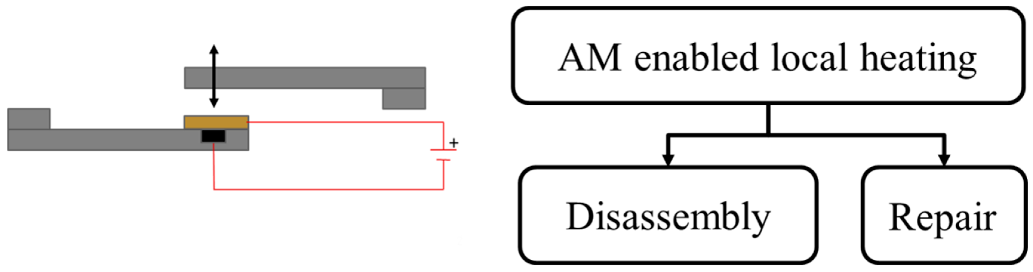
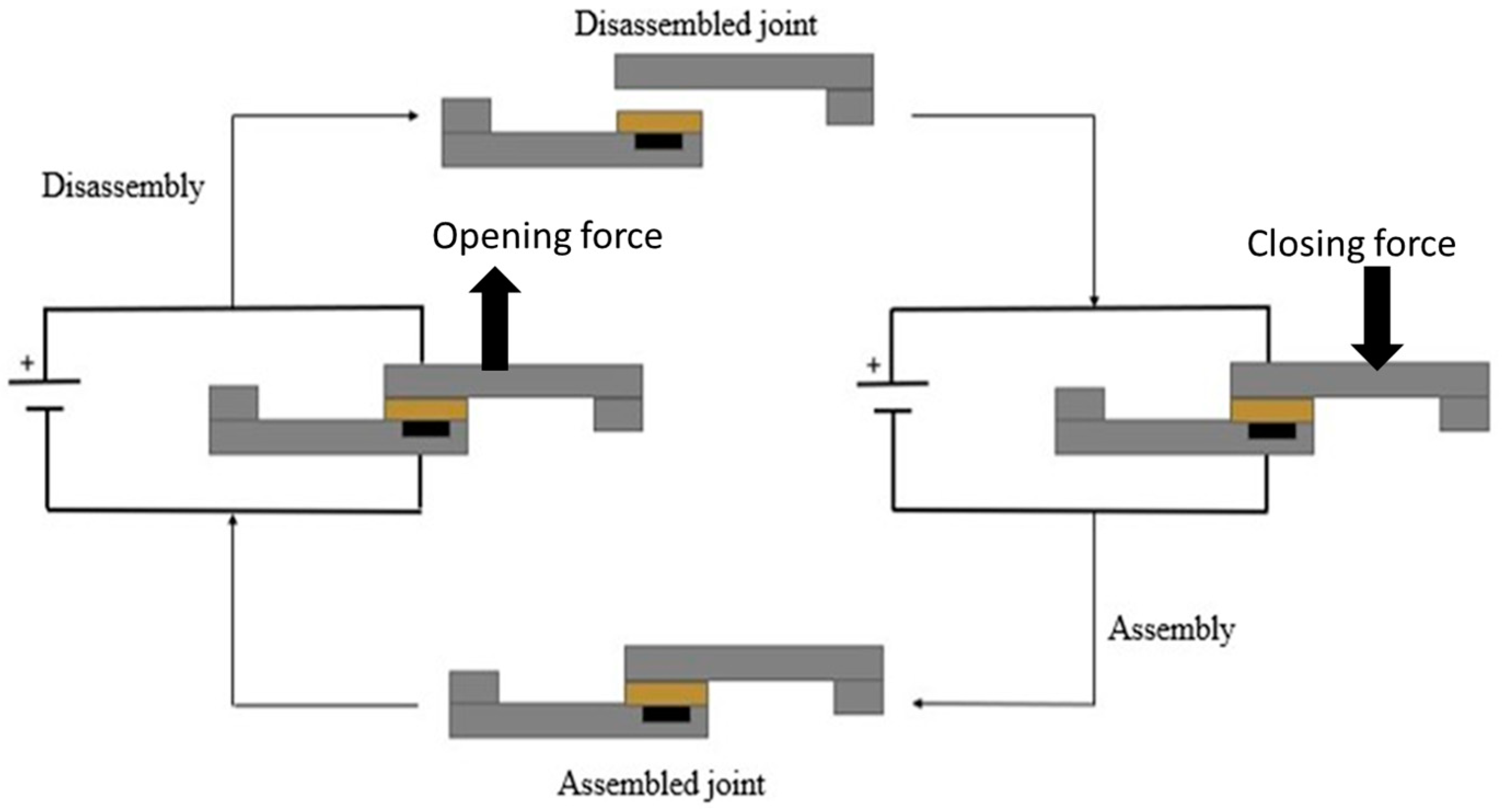
1.1. Workflow
1.2. Objectives
2. Materials and Methods
2.1. Materials
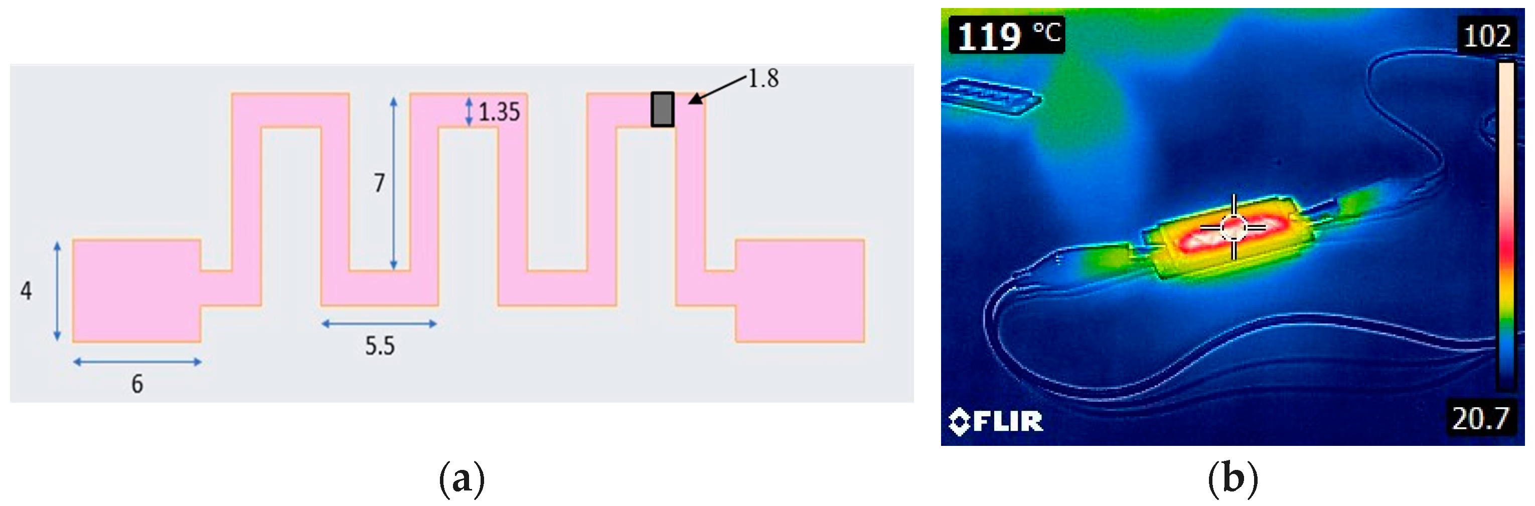
2.2. Concept Modeling and Validation
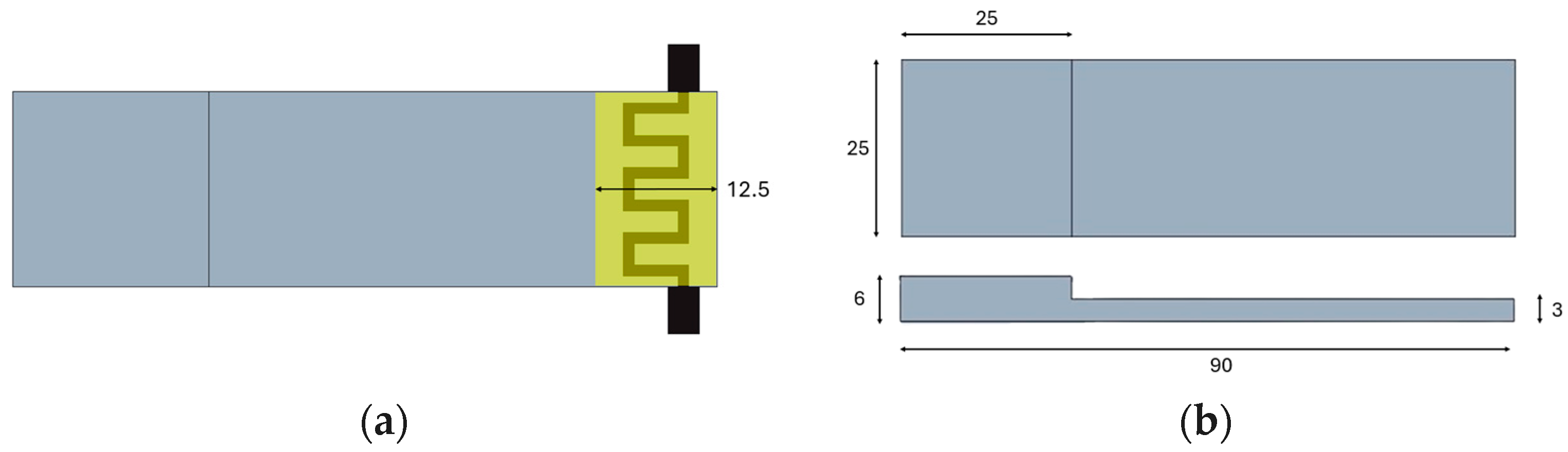
2.3. SLJ Design
2.4. Experimental Setup
3. Experimental Tests Setups
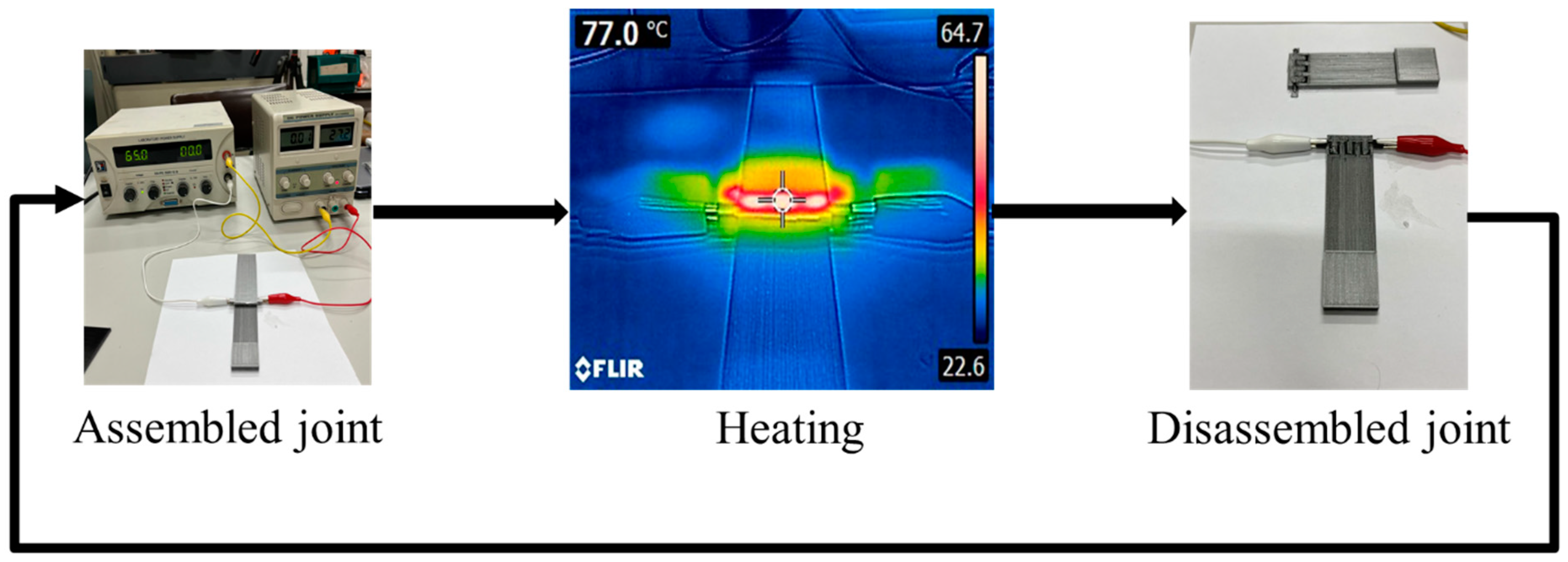
3.1. Preliminary Disassembly Tests
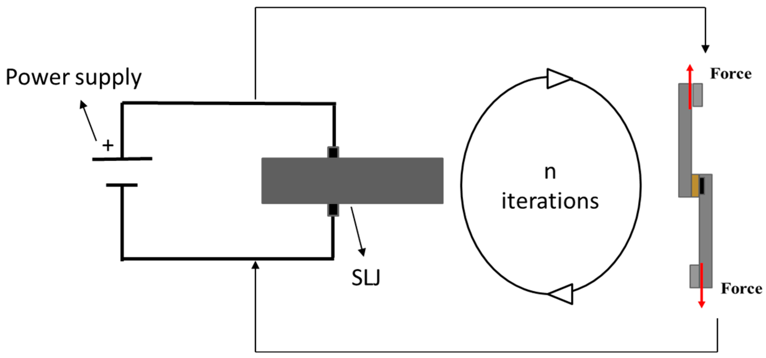
3.2. Tensile Tests Combined to Joints Healing
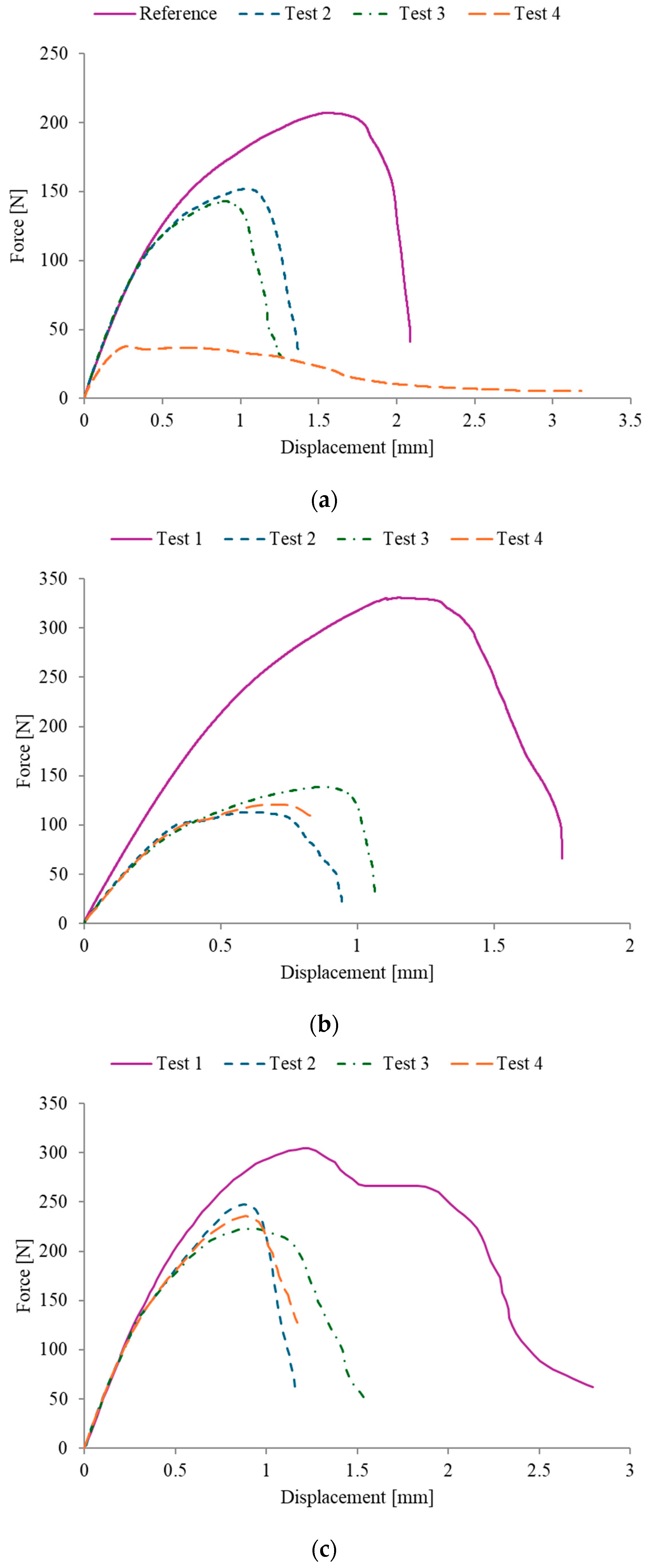
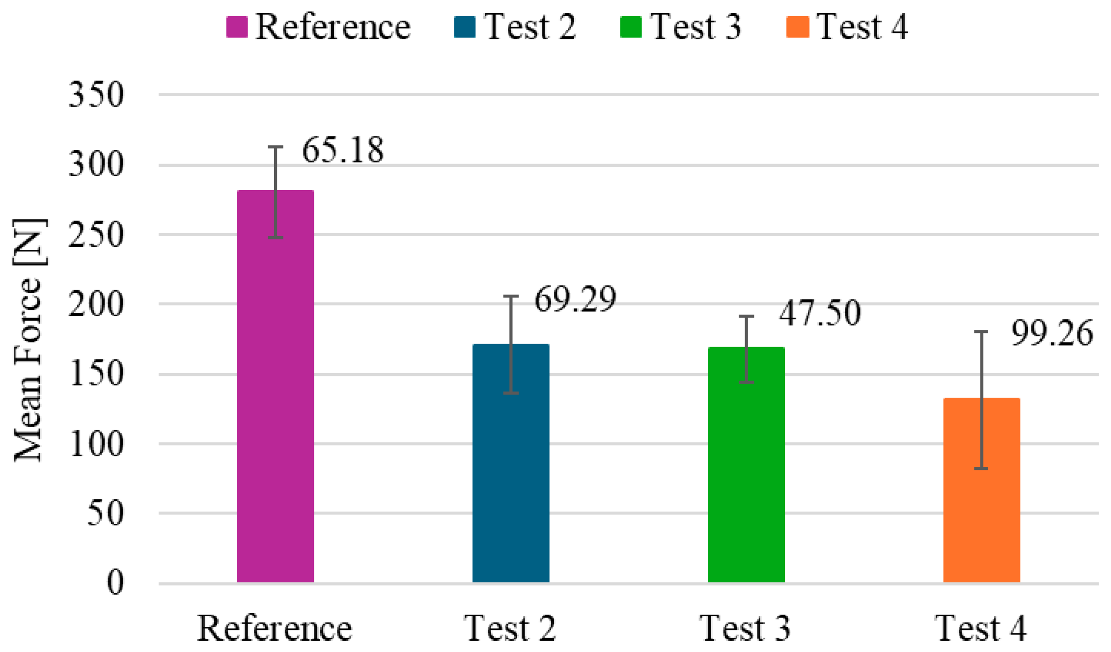
4. Results and Discussion
5. Conclusions
Supplementary Materials
Author Contributions
Funding
Institutional Review Board Statement
Informed Consent Statement
Data Availability Statement
Conflicts of Interest
References
- Paleari, S. The EU policy on climate change, biodiversity and circular economy: Moving towards a Nexus approach. Environ. Sci. Policy 2024, 151, 103603. [Google Scholar] [CrossRef]
- Machin, A.; Tan, E. Green European citizenship? Rights, duties, virtues, practices and the European Green Deal. Eur. Politics Soc. 2024, 25, 152–167. [Google Scholar] [CrossRef]
- Hereu-Morales, J.; Segarra, A.; Valderrama, C. The European (Green?) Deal: A systematic analysis of environmental sustainability. Sustain. Dev. 2024, 32, 647–661. [Google Scholar] [CrossRef]
- Ngo, T.D.; Kashani, A.; Imbalzano, G.; Nguyen, K.T.Q.; Hui, D. Additive manufacturing (3D printing): A review of materials, methods, applications and challenges. In Composites Part B: Engineering; Elsevier Ltd.: Amsterdam, The Netherlands, 2018; Volume 143, pp. 172–196. [Google Scholar] [CrossRef]
- Anaç, N. Assessment of Adhesively Bonded Joints of Similar and Dissimilar Materials: Industrial Case Study. Processes 2023, 11, 1312. [Google Scholar] [CrossRef]
- Zheng, X.; Williams, C.; Spadaccini, C.M.; Shea, K. Perspectives on multi-material additive manufacturing. J. Mater. Res. 2021, 36, 3549–3557. [Google Scholar] [CrossRef]
- Penumakala, P.K.; Santo, J.; Thomas, A. A critical review on the fused deposition modeling of thermoplastic polymer composites. In Composites Part B: Engineering; Elsevier Ltd.: Amsterdam, The Netherlands, 2020; Volume 201. [Google Scholar]
- Bandyopadhyay, A.; Heer, B. Additive manufacturing of multi-material structures. In Materials Science and Engineering R: Reports; Elsevier Ltd.: Amsterdam, The Netherlands, 2018; Volume 129, pp. 1–16. [Google Scholar]
- Mirzaali, M.J.; de la Nava, A.H.; Gunashekar, D.; Nouri-Goushki, M.; Doubrovski, E.L.; Zadpoor, A.A. Fracture behavior of bio-inspired functionally graded soft-hard composites made by multi-material 3D printing: The case of colinear cracks. Materials 2019, 12, 2735. [Google Scholar] [CrossRef]
- Hasanov, S.; Alkunte, S.; Rajeshirke, M.; Gupta, A.; Huseynov, O.; Fidan, I.; Rennie, A. Review on additive manufacturing of multi-material parts: Progress and challenges. J. Manuf. Mater. Process. 2022, 6, 4. [Google Scholar] [CrossRef]
- Chen, H.; Guo, L.; Zhu, W.; Li, C. Recent Advances in Multi-Material 3D Printing of Functional Ceramic Devices. Polymers 2022, 14, 4635. [Google Scholar] [CrossRef] [PubMed]
- Kristiawan, R.B.; Imaduddin, F.; Ariawan, D.; Ubaidillah Arifin, Z. A review on the fused deposition modeling (FDM) 3D printing: Filament processing, materials, and printing parameters. In Open Engineering; De Gruyter Open Ltd.: Warsaw, Poland, 2021; Volume 11, pp. 639–649. [Google Scholar]
- Avalle, M.; Monti, M.; Frascio, M. Modeling the strength of laminated parts made by fused filament fabrication additive manufacturing. Proc. Inst. Mech. Eng. Part C J. Mech. Eng. Sci. 2023, 09544062231161438. [Google Scholar] [CrossRef]
- Frascio, M.; Avalle, M.; Monti, M. Fatigue strength of plastics components made in additive manufacturing: First experimental results. Procedia Struct. Integr. 2018, 12, 32–43. [Google Scholar] [CrossRef]
- Bergonzi, L.; Pirondi, A.; Moroni, F.; Frascio, M.; Avalle, M. A study on Fused Filament Fabrication (FFF) parameters as bonded joint design factors. J. Adhes. 2021, 100, 576–605. [Google Scholar] [CrossRef]
- Moroni, F.; Pirondi, A.; Bergonzi, L.; Vettori, M. Influence of infill percentage on the mode I fracture toughness of adhesively bonded Double Cantilever Beam joints with Additively Manufactured PLA adherends Influence of infill percentage on the mode I fracture toughness of adhesively bonded Double Cantilever Beam joints with Additively Manufactured PLA adherends. IOP Conf. Ser. Mater. Sci. Eng. 2021, 1038, 012054. [Google Scholar] [CrossRef]
- Frascio, M.; Moroni, F.; Marques, E.; Carbas, R.J.C.; dos Reis, M.Q.; Monti, M.; Avalle, M.; da Silva, L. Feasibility study on hybrid weld-bonded joints using additive manufacturing and conductive thermoplastic filament. J. Adv. Join. Process. 2021, 1, 100046. [Google Scholar] [CrossRef]
- Frascio, M.; Marques, E.A.D.S.; Carbas, R.J.C.; da Silva, L.F.M.; Monti, M.; Avalle, M. Review of Tailoring Methods for Joints with Additively Manufactured Adherends and Adhesives. Materials 2020, 13, 3949. [Google Scholar] [CrossRef] [PubMed]
- Spaggiari, A.; Orlandini, S. Mechanical Strength of Additive Manufactured and Standard Polymeric Components Joined Through Structural Adhesives. Polymers 2024, 16, 3036. [Google Scholar] [CrossRef] [PubMed]
- Spaggiari, A.; Castagnetti, D.; Dragoni, E. A design oriented multiaxial stress-based criterion for the strength assessment of adhesive layers. Compos. Part B Eng. 2019, 157, 66–75. [Google Scholar] [CrossRef]
- Benli, İ.K.; Anaç, N.; Koçar, O.; da Silva, L.F. The effects of material type and temperature factors on the adhesive bonding strength of 3D printed multi-material plastic structures. Proc. Inst. Mech. Eng. Part L J. Mater. Des. Appl. 2024, 14644207241275821. [Google Scholar] [CrossRef]
- Banea, M.D.; Rosioara, M.; Carbas, R.J.C.; da Silva, L.F.M. Multi-material adhesive joints for automotive industry. Compos. B Eng. 2018, 151, 71–77. [Google Scholar] [CrossRef]
- Spaggiari, A.; Favali, F. Evaluation of polymeric 3D printed adhesively bonded joints: Effect of joint morphology and mechanical interlocking. Rapid Prototyp. J. 2022, 28, 1437–1451. [Google Scholar] [CrossRef]
- Barbosa, N.G.C.; Campilho, R.D.S.G.; Silva, F.J.G.; Moreira, R.D.F. Comparison of different adhesively-bonded joint types for mechanical structures. Appl. Adhes. Sci. 2018, 6, 15. [Google Scholar] [CrossRef]
- Handbook of Adhesion Technology; da Silva, L.F.M., Öchsner, A., Adams, R.D., Eds.; Springer International Publishing: Cham, Switzerland, 2018. [Google Scholar]
- Jia, Z.; Yu, J.; Liu, Q.; Yu, S.; Wang, Z. Functionally graded adhesive joints with exceptional strength and toughness by graphene nanoplatelets reinforced epoxy adhesives. Int. J. Adhes. Adhes. 2023, 125, 103402. [Google Scholar] [CrossRef]
- Nakanouchi, M.; Sato, C.; Sekiguchi, Y.; Haraga, K.; Uno, H. Development of application method for fabricating functionally graded adhesive joints by two-component acrylic adhesives with different elastic moduli. J. Adhes. 2019, 95, 529–542. [Google Scholar] [CrossRef]
- Borges, C.S.P.; Akhavan-Safar, A.; Tsokanas, P.; Carbas, R.J.C.; Marques, E.A.S.; da Silva, L.F.M. From fundamental concepts to recent developments in the adhesive bonding technology: A general view. Discov. Mech. Eng. 2023, 2, 8. [Google Scholar] [CrossRef]
- Naat, N.; Boutar, Y.; Mezlini, S.; da Silva, L.F.M.; Alrasheedi, N.H.; Hajlaoui, K. Study of the effect of bio-inspired surface texture on the shear strength of bonded 3D-printed materials: Comparison between stainless steel and polycarbonate joints. Int. J. Adhes. Adhes. 2024, 131, 103658. [Google Scholar] [CrossRef]
- Hu, N.; Shu, L.; Zheng, X.; Deng, Z.; Cang, X. A review of modification methods, joints and self-healing methods of adhesive for aerospace. Sci. Prog. 2024, 107, 00368504241242271. [Google Scholar] [CrossRef]
- Wang, Y.T.; Liang, H.; Wei, Y.; Wang, J.L.; He, X.M.; Yang, Y. A Simple-Prepared and Multi-Reusable Adhesive Based on Epoxy Vitrimer. Chin. J. Polym. Sci. 2024, 42, 1589–1594. [Google Scholar] [CrossRef]
- Yuan, Y.; Zhu, S.; Zhu, J.; Niu, P.; Sun, A.; Liu, X.; Wei, L.; Li, Y. An impact-strengthening, reusable hot-melt structural adhesive derived from branching polyurethane-based supramolecular topology capped by self-complementary hydrogen bonding UPy motifs. Eur. Polym. J. 2023, 196, 112253. [Google Scholar] [CrossRef]
- Banea, M.D. Debonding on Demand of Adhesively Bonded Joints: A Critical Review. Rev. Adhes. Adhes. 2019, 7, 33–50. [Google Scholar] [CrossRef]
- Dong, W.; Gu, X.; Han, J.; You, L. Universal Adhesives- Different Curing Methods and Applications. In E3S Web of Conferences; EDP Sciences: Les Ulis, France, 2021. [Google Scholar]
- Cebrián, A.S.; Zurich, E.; Ermanni, P.; Moser, P.; Zogg, M. Paste Adhesive Modification for Induction Curing; SAMPE: Baltimore, MD, USA, 2012. [Google Scholar]
- Carbas, R.J.C.; Da Silva, L.F.M.; Critchlow, G.W. Adhesively bonded functionally graded joints by induction heating. Int. J. Adhes. Adhes. 2014, 48, 110–118. [Google Scholar] [CrossRef]
- Banea, M.D.; da Silva, L.F.M.; Carbas, R.J.C. Debonding on command of adhesive joints for the automotive industry. Int. J. Adhes. Adhes. 2015, 59, 14–20. [Google Scholar] [CrossRef]
- Frascio, M.; Zafferani, A.; Monti, M.; Avalle, M. Investigating enhanced interfacial adhesion in multi-material filament 3D printing: A comparative study of t and Mickey Mouse geometries. Prog. Addit. Manuf. 2024, 9, 2113–2122. [Google Scholar] [CrossRef]
- Farah, S.; Anderson, D.G.; Langer, R. Physical and mechanical properties of PLA, and their functions in widespread applications —A comprehensive review. In Advanced Drug Delivery Reviews; Elsevier: Amsterdam, The Netherlands, 2016; Volume 107, pp. 367–392. [Google Scholar]
- Tirado-Garcia, I.; Garcia-Gonzalez, D.; Garzon-Hernandez, S.; Rusinek, A.; Robles, G.; Martinez-Tarifa, J.M.; Arias, A. Conductive 3D printed PLA composites: On the interplay of mechanical, electrical and thermal behaviours. Compos. Struct. 2021, 265, 113744. [Google Scholar] [CrossRef]
- Flowers, P.F.; Reyes, C.; Ye, S.; Kim, M.J.; Wiley, B.J. 3D printing electronic components and circuits with conductive thermoplastic filament. Addit. Manuf. 2017, 18, 156–163. [Google Scholar] [CrossRef]
- Gilleo, K.; Ongley, P. Pros and cons of thermoplastic and thermoset polymer adhesives in microelectronic assembly applications. Microelectron. Int. 1999, 16, 34–38. [Google Scholar] [CrossRef]
- da Silva, C.I.; Barbosa, A.Q.; Marques, J.B.; Carbas, R.J.C.; Marques, E.A.S.; Abenojar, J.; da Silva, L.F. Mechanical characterisation of graded single lap joints using magnetised cork microparticles. In Advanced Structured Materials; Springer: Berlin/Heidelberg, Germany, 2020; pp. 153–174. [Google Scholar]
- ISO 16237; BSI Standards Publication Mechanical Joining-Destructive Testing of Joints-Specimen Dimensions and Test Procedure for Cross-Tension Testing of Single Joints. ISO: Geneva, Switzerland, 2015.
- ASTM D4896-01; Guide for Use of Adhesive-Bonded Single Lap-Joint Specimen Test Results. ASTM International: West Conshohocken, PA, USA, 2024.
- ASTM D3165-07; Standard Test Method for Strength Properties of Adhesives in Shear by Tension Loading of Single-Lap-Joint Laminated Assemblies. ASTM International: West Conshohocken, PA, USA, 2023.
- Frascio, M.; Bergonzi, L.; Jilich, M.; Moroni, F.; Avalle, M.; Pirondi, A.; Vettori, M. Additive manufacturing process parameter influence on mechanical strength of adhesive joints, preliminary activities. Acta Polytech. CTU Proc. 2019, 25, 41–47. [Google Scholar] [CrossRef]
- Kiendl, J.; Gao, C. Controlling toughness and strength of FDM 3D-printed PLA components through the raster layup. Compos. B Eng. 2020, 180, 107562. [Google Scholar] [CrossRef]
- Rossi, G.B.; Crenna, F. A first-order probabilistic logic with application to measurement representations. Measurement 2016, 79, 251–259. [Google Scholar] [CrossRef]
- Rossi, G.B.; Crenna, F.; Palazzo, A. A Proposal for a More User-Oriented GUM. IEEE Trans. Instrum. Meas. 2019, 68, 1343–1352. [Google Scholar] [CrossRef]
- Crenna, F.; Rossi, G.B.; Bovio, L. Probabilistic measurement evaluation for the implementation of the Measuring Instrument Directive. Measurement 2009, 42, 1522–1531. [Google Scholar] [CrossRef]
- Rahmatabadi, D.; Aberoumand, M.; Soltanmohammadi, K.; Soleyman, E.; Ghasemi, I.; Baniassadi, M.; Abrinia, K.; Zolfagharian, A.; Bodaghi, M.; Baghani, M. A New Strategy for Achieving Shape Memory Effects in 4D Printed Two-Layer Composite Structures. Polymers 2022, 14, 5446. [Google Scholar] [CrossRef] [PubMed]
- Rahmatabadi, D.; Aberoumand, M.; Soltanmohammadi, K.; Soleyman, E.; Ghasemi, I.; Baniassadi, M.; Abrinia, K.; Bodaghi, M.; Baghani, M. 4D Printing-Encapsulated Polycaprolactone–Thermoplastic Polyurethane with High Shape Memory Performances. Adv. Eng. Mater. 2023, 25, 2201309. [Google Scholar] [CrossRef]


| Number of Repairs | 1 | 2 | 3 |
|---|---|---|---|
| Percent decrease in maximum force [%] | 39% | 40% | 53% |
Disclaimer/Publisher’s Note: The statements, opinions and data contained in all publications are solely those of the individual author(s) and contributor(s) and not of MDPI and/or the editor(s). MDPI and/or the editor(s) disclaim responsibility for any injury to people or property resulting from any ideas, methods, instructions or products referred to in the content. |
© 2025 by the authors. Licensee MDPI, Basel, Switzerland. This article is an open access article distributed under the terms and conditions of the Creative Commons Attribution (CC BY) license (https://creativecommons.org/licenses/by/4.0/).
Share and Cite
Frascio, M.; Morchio, S.; Musiari, F.; Muhammad Usman, K.; Dittamo, F.; Minuto, M.; Avalle, M. Investigating Multi-Material Additive Manufacturing for Disassembly and Reparability of Adhesive Joints by Precision Heating. Adhesives 2025, 1, 4. https://doi.org/10.3390/adhesives1010004
Frascio M, Morchio S, Musiari F, Muhammad Usman K, Dittamo F, Minuto M, Avalle M. Investigating Multi-Material Additive Manufacturing for Disassembly and Reparability of Adhesive Joints by Precision Heating. Adhesives. 2025; 1(1):4. https://doi.org/10.3390/adhesives1010004
Chicago/Turabian StyleFrascio, Mattia, Stefano Morchio, Francesco Musiari, Khalid Muhammad Usman, Federico Dittamo, Matilde Minuto, and Massimiliano Avalle. 2025. "Investigating Multi-Material Additive Manufacturing for Disassembly and Reparability of Adhesive Joints by Precision Heating" Adhesives 1, no. 1: 4. https://doi.org/10.3390/adhesives1010004
APA StyleFrascio, M., Morchio, S., Musiari, F., Muhammad Usman, K., Dittamo, F., Minuto, M., & Avalle, M. (2025). Investigating Multi-Material Additive Manufacturing for Disassembly and Reparability of Adhesive Joints by Precision Heating. Adhesives, 1(1), 4. https://doi.org/10.3390/adhesives1010004