1. Introduction
Firebrands are an important fire spread mechanism in addition to gas radiation and convection, and they play a crucial role in wildfires, where their impact is known as fire spotting and is a leading cause of house loss in the Wildland–Urban Interface (WUI). Firebrand transport has been extensively studied in the past with increasing complexity [
1,
2,
3].
This work focuses on the detailed calculation of terminal velocity on a small scale under controlled environments with varying simulation complexity. The aim is to provide refined terminal velocities of a representative set of firebrands [
4] for large-scale simulations [
5,
6,
7,
8,
9]. Unlike previous work, we focus not only on generic firebrand shapes like discs and cylinders but also on real firebrand shapes collected previously [
4].
2. Methods
2.1. Description of Firebrand
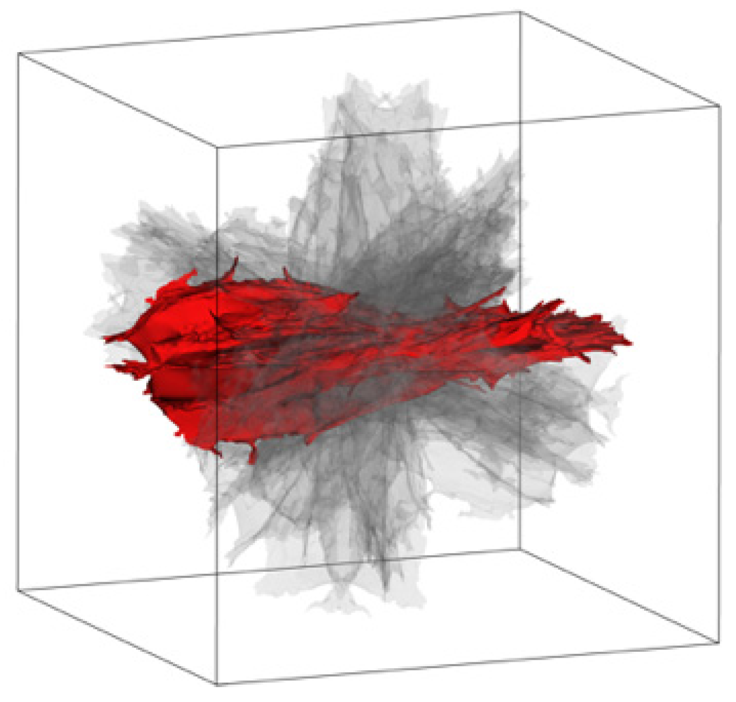
The methodology covers 11 different orientations, varying Reynolds numbers, and two mesh settings, using a RANS modelling approach based on velocity-dependent force curves. In its current state, the terminal velocity is evaluated for a single representative firebrand, which is candle bark (see
Figure 1). The shape was collected during experiments and later determined by photometry. The selected firebrand has a bounding box of approximately −0.069 m, 0.022 m, −0.0 m to 0.069 m, 0.022 m, 0.052 m, a volume of about 5.143 × 10
−5 m
3, and, with a measured mass of 3.717 g, a resulting density of 131.81 kg/m
3.
2.2. Description of Orientation
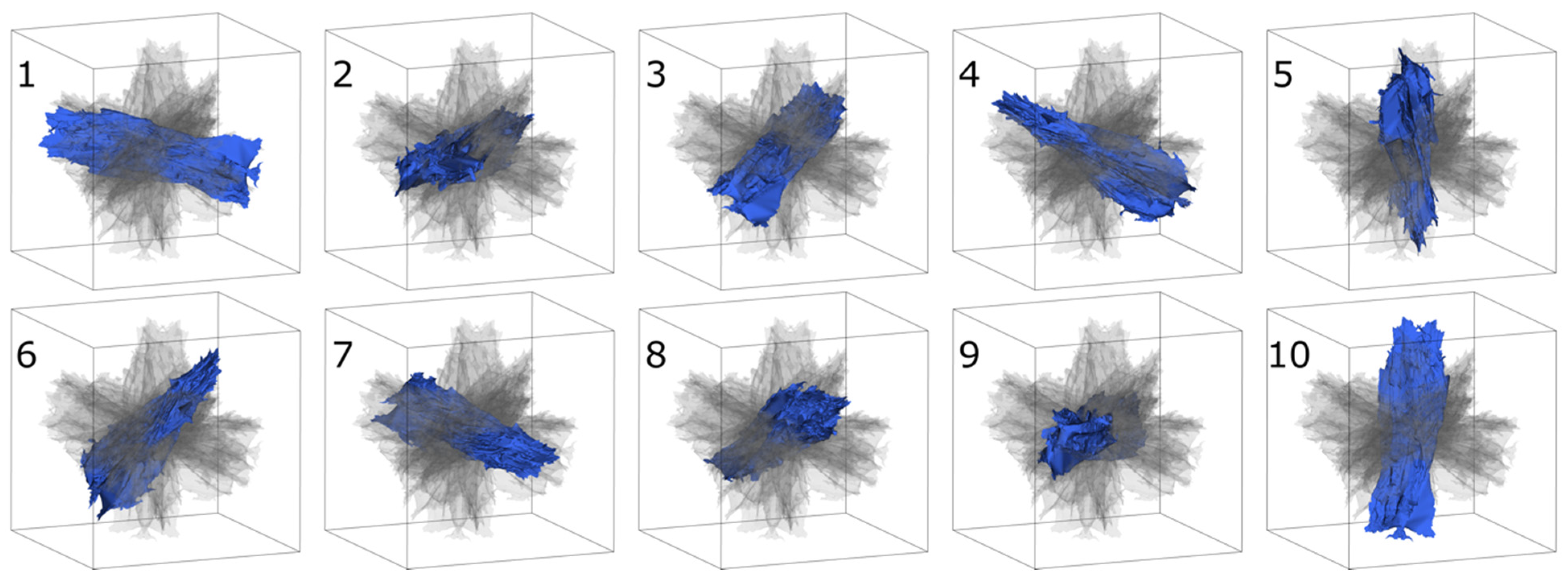
The original scanned geometry was later used to create 10 additional variations by applying random rotations, rolls, and pivots. At this stage, the goal is not to achieve a perfectly statistically distributed set of orientations, but rather to establish an initial setup to study the terminal velocity variations of the selected firebrand.
Figure 2 illustrates the generated firebrand variations for all 10 additional orientations.
2.3. Simulation Setup
In the current state, the firebrands are placed in a generic wind tunnel setup (domain size of 3 m, 3 m, 2.5 m) with a block inlet profile, a turbulence intensity of 10%, a mixing length of 0.1 m, at an ambient temperature of 300 K and an ambient density of 1.0 kg/m
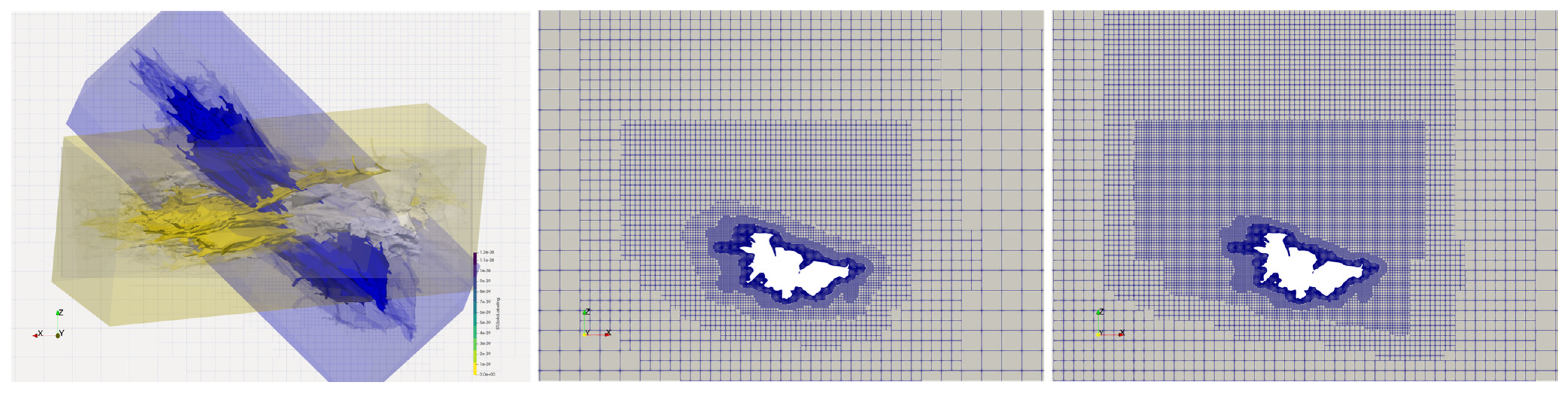
3. Inlet velocities were varied between 3 m/s and 10 m/s for all 11 orientations. Steady RANS-based simulations were conducted using two different turbulence models (k-epsilon and k-omega-SST) in OpenFOAM (v2506). To avoid any impact of mesh settings across different orientations, an automated meshing approach was chosen to ensure that refinement levels and refinement zones around the firebrand remain consistent regardless of orientation. See
Figure 3 (left), which highlights the main refinement zones around the firebrand for two orientations. The simulation setup is automated with the application in mind for high-performance computing systems, enabling multiple complex scenarios to be generated with minimal setup effort. An initial mesh refinement was also investigated. The meshes differ only in the refinement level around the firebrand, resulting in approximately 17.5 million cells for the initial mesh and about 18.3 million cells for the refined mesh.
Further mesh refinement studies are planned, with continued emphasis on generating high-quality automatic meshes for complex shapes.
3. Results and Discussion
With variations in inlet velocity, mesh setup, turbulence model, and orientation, a total of 352 simulations were carried out. As the primary focus is on the terminal velocity, force-velocity relations were created from the resulting simulations. Terminal velocity was then derived separately for each orientation. For the current setup, the impact of the turbulence model is negligible, so no further evaluation is shown here. The two chosen mesh setups are quite similar, so the resulting terminal velocity differences are also not shown here.
Compared to the other settings, there is a strong dependence of the calculated terminal velocity on orientation and inlet velocity.
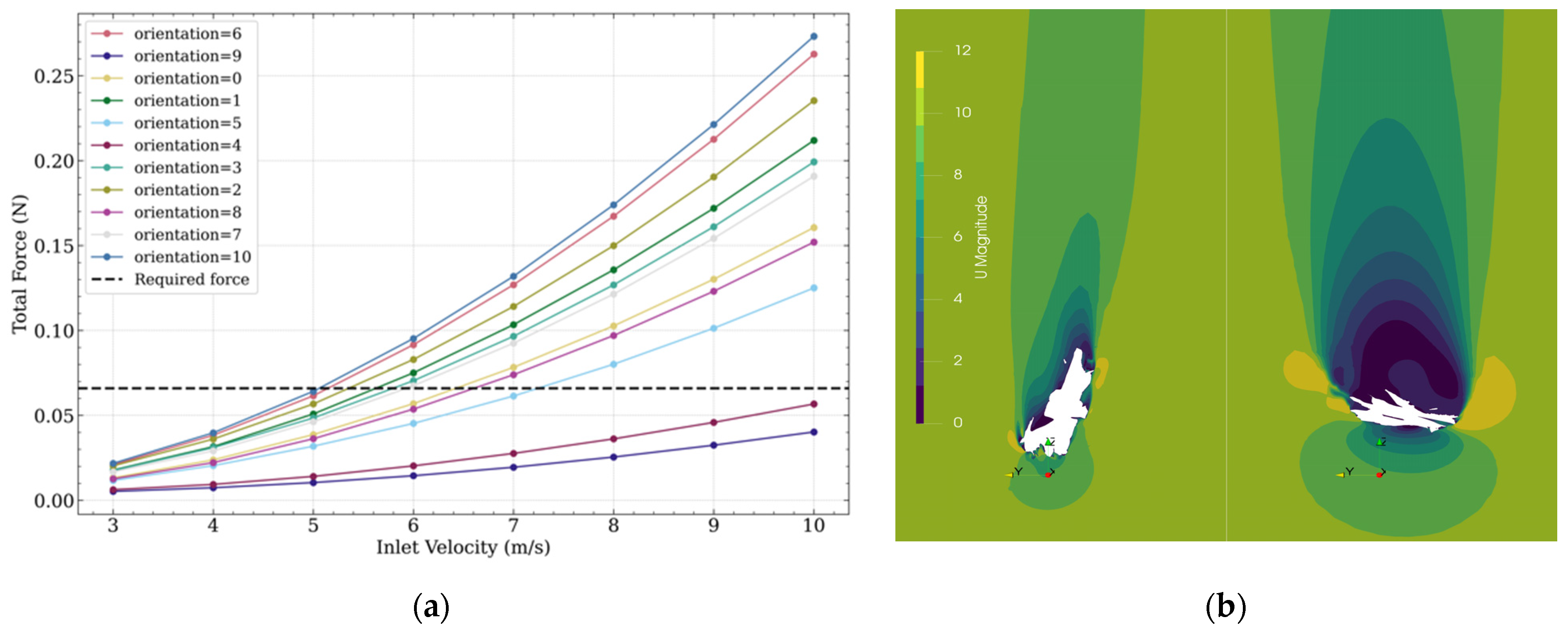
Figure 4 shows the force-velocity curve for the k-omega-SST setup with a 17.5-million-cell mesh.
The results show that the terminal velocity ranges from approximately 5 m/s to 11 m/s, with a mean velocity of about 6.5 m/s, skewed toward lower values.
Figure 4 (right) visualizes the flow velocity in a selected slice at position x=0.0 m for orientations 4 and 6, which exhibit very different terminal velocities. It is clear that orientation has a significant impact on the flow field and, consequently, on the resulting forces. Orientation 4 produces a much smaller total frontal area compared to orientation 6.
It is noted that these calculated firebrand terminal velocities are derived for a well-known and fixed scenario. That is, the actual behaviour will vary during firebrand transport in real conditions due to factors such as changing shape and density caused by combustion and ambient conditions. Nevertheless, the current approach provides initial insight into model sensitivities. Furthermore, the orientation of the firebrands is dynamic; a fixed position is not realistic, and rotating orientations are highly probable.
4. Conclusions
The work highlights the impact of orientation on the terminal velocity for a selected candle bark firebrand. The calculated terminal velocity ranges from 5 to 11 m/s for the selected setup.
Further mesh refinement studies are needed, and more detailed LES or hybrid RANS-LES simulations are planned for selected orientations and setups. The next steps will also include validation calculations using wind tunnel measurements of generic disc and cylinder shapes at various fixed orientations. The same approach will be applied to complex firebrand shapes.
Author Contributions
Conceptualization, F.B., M.A., H.-N.N., A.F., A.L.S. and J.-B.F.; methodology, F.B., M.A., H.-N.N., A.F., A.L.S. and J.-B.F.; software, F.B.; formal analysis, F.B., M.A., H.-N.N., A.F., A.L.S. and J.-B.F.; resources, F.B.; writing—original draft preparation, F.B. and M.A.; writing—review and editing, F.B., M.A., H.-N.N., A.F., A.L.S. and J.-B.F.; visualization, F.B. All authors have read and agreed to the published version of the manuscript.
Funding
This research received no external funding.
Institutional Review Board Statement
Not applicable.
Informed Consent Statement
Not applicable.
Data Availability Statement
The original contributions presented in this study are included in the article. Further inquiries can be directed to the corresponding author.
Acknowledgments
The computations were carried out on the Pleiades cluster at the University of Wuppertal, which was supported by the Deutsche Forschungsgemeinschaft (DFG), Germany, and the Bundesministerium für Bildung und Forschung (BMBF). During the preparation of this manuscript/study, the authors used ChatGPT GPT-5.5 for correction purposes. The authors have reviewed and edited the output and take full responsibility for the content of this publication.
Conflicts of Interest
The authors declare no conflicts of interest. The funders had no role in the design of the study; in the collection, analyses, or interpretation of data; in the writing of the manuscript; or in the decision to publish the results.
References
- Filkov, A.I.; Tihay-Felicelli, V.; Masoudvaziri, N.; Rush, D.; Valencia, A.; Wang, Y.; Blunck, D.L.; Valero, M.M.; Kempna, K.; Smolka, J.; et al. A review of thermal exposure and fire spread mechanisms in large outdoor fires and the built environment. Fire Saf. J. 2023, 140, 103871. [Google Scholar] [CrossRef] [Scilit]
- Tohidi, A.; Kaye, N.B. Aerodynamic characterization of rod-like debris with application to firebrand transport. J. Wind. Eng. Ind. Aerodyn. 2017, 168, 297–311. [Google Scholar] [CrossRef] [Scilit]
- Koo, E.; Linn, R.R.; Pagni, P.J.; Edminster, C.B. Modelling firebrand transport in wildfires using HIGRAD/FIRETEC. Int. J. Wildland Fire 2012, 21, 396–417. [Google Scholar] [CrossRef] [Scilit]
- Nguyen, H.-N.; Filippi, J.-B.; Peace, M.; Penman, T.D.; Cawson, J.; Filkov, A.I. A Laboratory Framework for Firebrand Generation: Linking Fuel and Fire Parameters to Firebrand Morphology. Faculty of Science, The University of Melbourne, 4 Water Street, Creswick, VIC 3363, Australia. 2026; manuscript in preparation.
- Clark, T.L.; Jenkins, M.A.; Coen, J.; Packham, D. A Coupled Atmosphere–Fire Model: Convective Feedback on Fire-Line Dynamics. J. Appl. Meteorol. Clim. 1996, 35, 875–901. [Google Scholar] [CrossRef] [PubMed]
- Linn, R.R.; Cunningham, P. Numerical simulations of grass fires using a coupled atmosphere–fire model: Basic fire behavior and dependence on wind speed. J. Geophys. Res. Atmos. 2005, 110. [Google Scholar] [CrossRef] [Scilit]
- Peace, M.; Charney, J.; Bally, J. Lessons Learned from Coupled Fire-Atmosphere Research and Implications for Operational Fire Prediction and Meteorological Products Provided by the Bureau of Meteorology to Australian Fire Agencies. Atmosphere 2020, 11, 1380. [Google Scholar] [CrossRef] [Scilit]
- Węgrzyński, W.; Lipecki, T. Wind and Fire Coupled Modelling—Part I: Literature Review. Fire Technol. 2018, 54, 1405–1442. [Google Scholar] [CrossRef] [Scilit]
- Alonso-Pinar, A.; Filippi, J.-B.; Nguyen, H.-N.; Filkov, A. A simplified model to incorporate firebrand transport into coupled fire atmosphere models. Int. J. Wildland Fire 2025, 34, WF24200. [Google Scholar] [CrossRef] [Scilit]
| Disclaimer/Publisher’s Note: The statements, opinions and data contained in all publications are solely those of the individual author(s) and contributor(s) and not of MDPI and/or the editor(s). MDPI and/or the editor(s) disclaim responsibility for any injury to people or property resulting from any ideas, methods, instructions or products referred to in the content. |



 ,
,