
Design of a Novel Ultra-Wideband Antipodal Vivaldi Antenna Based on Klopfenstein Curve


Abstract

1. Introduction
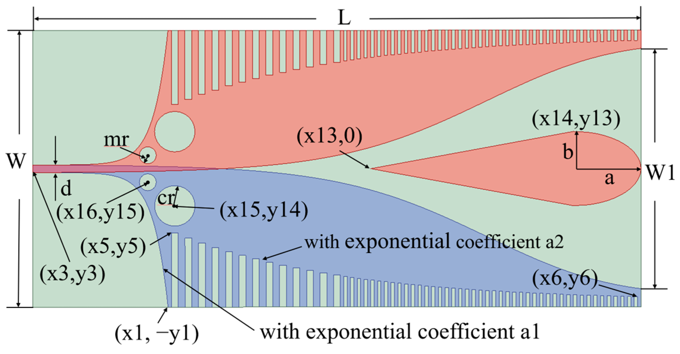
2. Design and Performance Analysis of Proposed Antenna Structure
2.1. Improved Impedance Matching with Klopfenstein Inner Curve Design
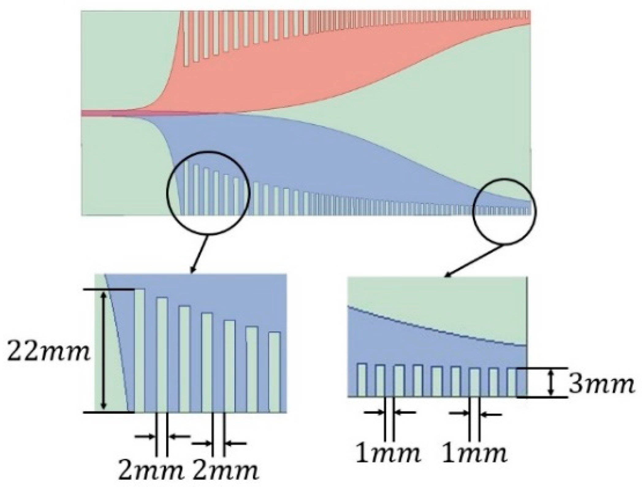
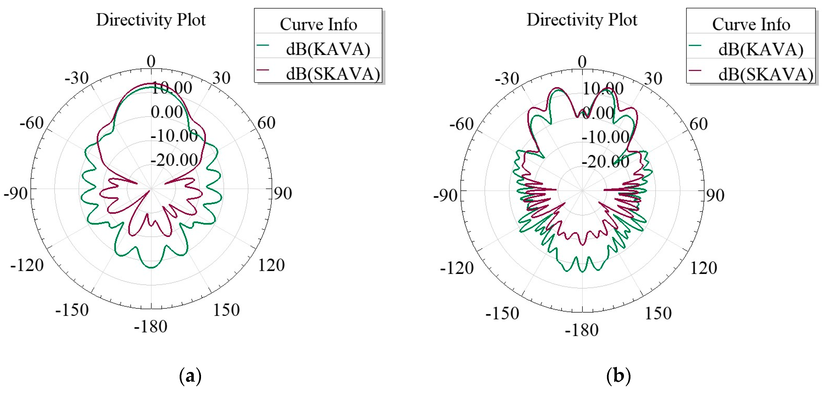
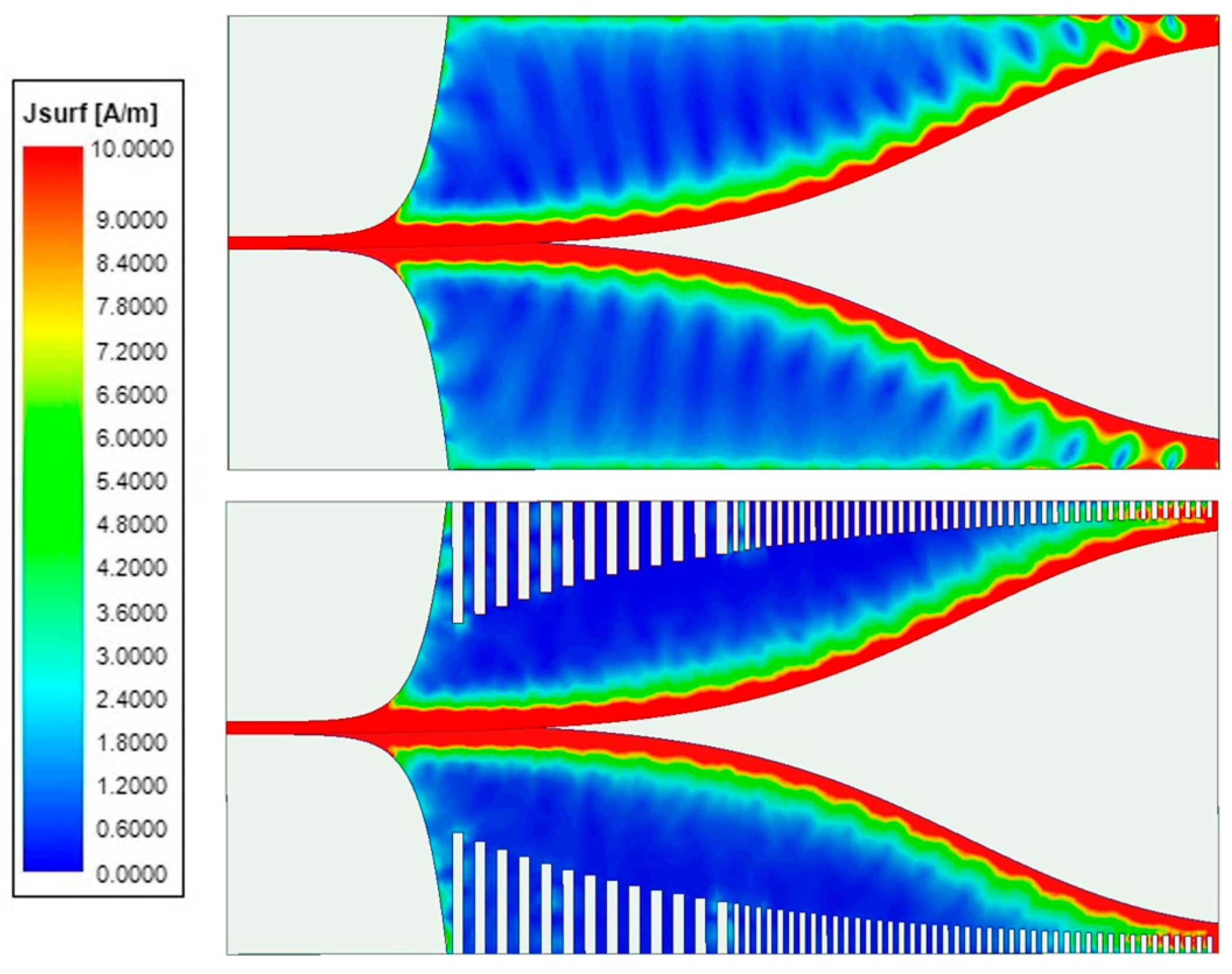
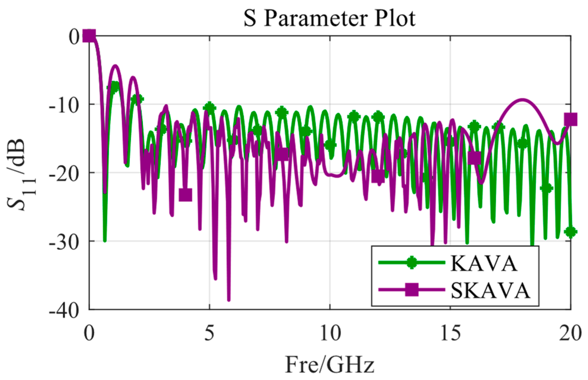
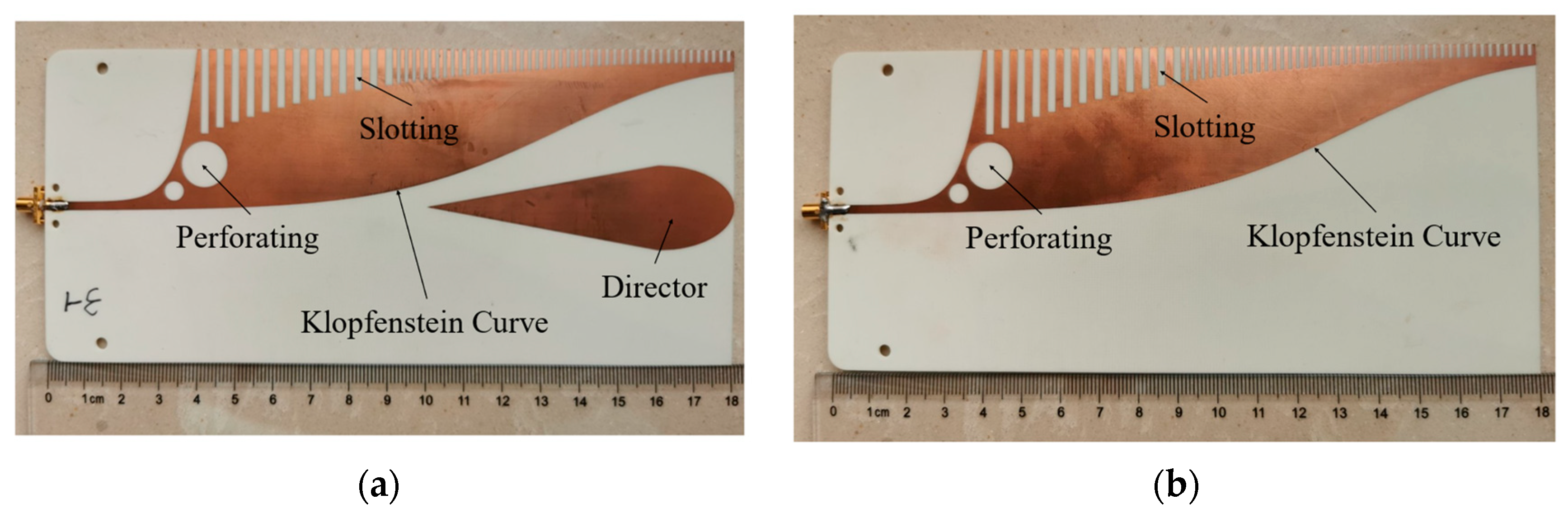
2.2. Sidelobe Suppression with Slotting Design
2.3. Gain Enhancement by Adding the Director
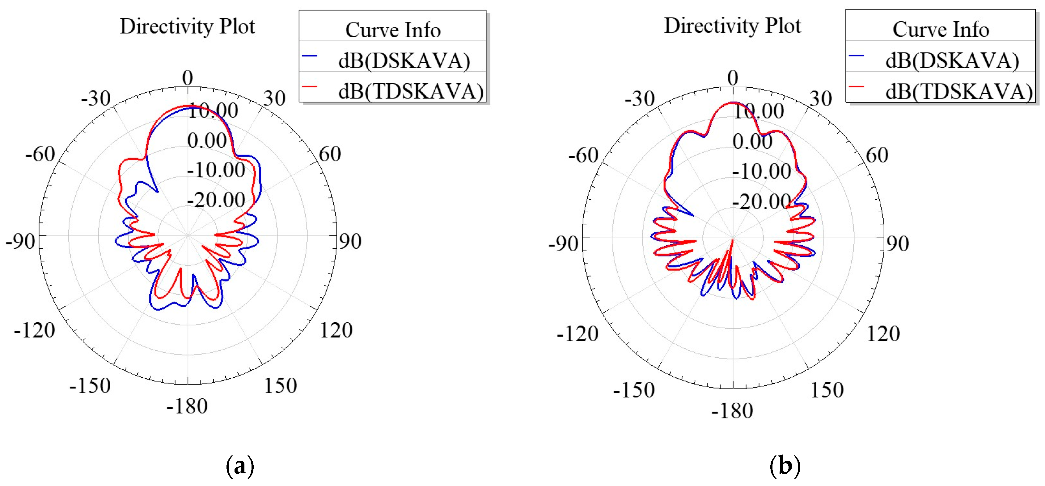
2.4. Further Sidelobe Suppression with Perforating Design
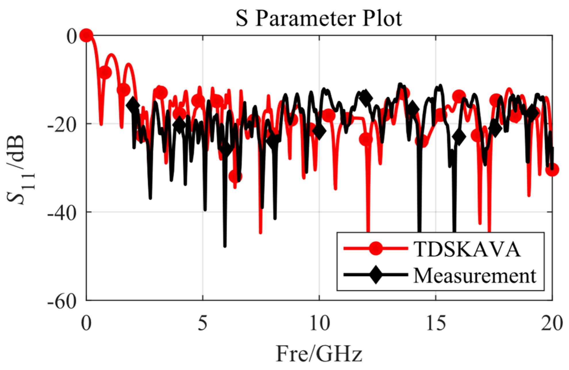
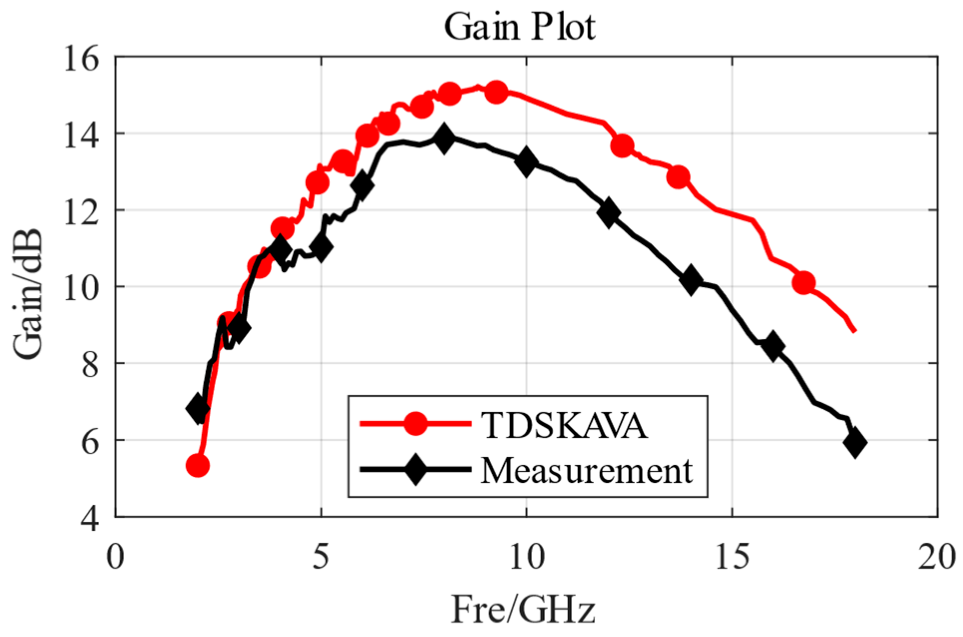
3. Antenna Measurement
4. Conclusions
Author Contributions
Funding
Institutional Review Board Statement
Informed Consent Statement
Data Availability Statement
Acknowledgments
Conflicts of Interest
Abbreviations
| AVA | Antipodal Vivaldi antenna |
| BAVA | Balanced antipodal Vivaldi antenna |
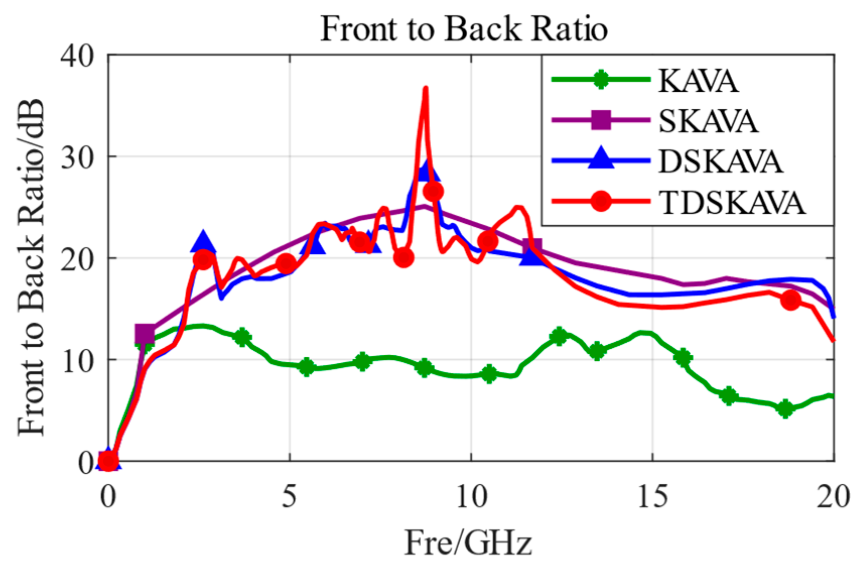
| KAVA | Klopfenstein curve Antipodal Vivaldi Antenna |
| SKAVA | Slotted Klopfenstein curve Antipodal Vivaldi Antenna |
| DSKAVA | Slotted Klopfenstein curve Antipodal Vivaldi Antenna with Director |
| TDSKAVA | Perforating Slotted Klopfenstein curve Antenna with Director |
References
- Moosazadeh, M.; Kharkovsky, S.; Esmati, Z.; Samali, B. UWB elliptically-tapered antipodal Vivaldi antenna for microwave imaging applications. In Proceedings of the 2016 IEEE-APS Topical Conference on Antennas and Propagation in Wireless Communications (APWC), Cairns, QLD, Australia, 19–23 September 2016; pp. 102–105. [Google Scholar] [CrossRef]
- Nassar, I.T.; Weller, T.M. A Novel Method for Improving Antipodal Vivaldi Antenna Performance. IEEE Trans. Antennas Propag. 2015, 63, 3321–3324. [Google Scholar] [CrossRef]
- Gazit, E. Improved design of the Vivaldi antenna. IEE Proc. H Microw. Antennas Propag. 1988, 135, 89–92. [Google Scholar] [CrossRef]
- Langley, J.D.S.; Hall, P.S.; Newham, P. Novel ultrawide-bandwidth Vivaldi antenna with low crosspolarisation. Electron. Lett. 1993, 29, 2004. [Google Scholar] [CrossRef]
- Liu, H.-X.; Gao, J.; Cao, X.; Liu, Y.-F.; Zhang, D.; Li, S.-J. A design of high-gain end-fire antenna based on split-ring resonator structures. Acta Phys. Sin. 2015, 64, 234101. [Google Scholar] [CrossRef]
- Huang, D.; Yang, H.; Wu, Y.; Zhao, F.; Liu, X. A high-gain antipodal Vivaldi antenna with multi-layer planar dielectric lens. Journal of Electromagnetic Waves and Applications. J. Electromagn. Waves Appl. 2017, 32, 403–412. [Google Scholar] [CrossRef]
- Pan, S.; Lin, M.; Qi, L.; Chen, P.; Feng, Y.; Li, G. Performance enhancement for antipodal Vivaldi antenna modulated by a high-permittivity metasurface lens. Front. Inf. Technol. Electron. Eng. 2021, 22, 1655–1665. [Google Scholar] [CrossRef]
- Gorai, A.; Karmakar, A.; Pal, M.; Ghatak, R. A super wideband Chebyshev tapered antipodal Vivaldi antenna. AEU Int. J. Electron. Commun. 2015, 69, 1328–1333. [Google Scholar] [CrossRef]
- Clavin, H.; Das, S.; Sharma, S.K. Design of a High Gain Broadband Balanced Antipodal Vivaldi Antenna with 3D Dielectric Lens. In Proceedings of the 2022 IEEE International Symposium on Antennas and Propagation and USNC-URSI Radio Science Meeting (AP-S/URSI), Denver, CO, USA, 10–15 July 2022; pp. 717–718. [Google Scholar] [CrossRef]
- Biswas, B.; Ghatak, R.; Poddar, D.R. A Fern Fractal Leaf Inspired Wideband Antipodal Vivaldi Antenna for Microwave Imaging System. IEEE Trans. Antennas Propag. 2017, 65, 6126–6129. [Google Scholar] [CrossRef]
- Klopfenstein, R.W. A Transmission Line Taper of Improved Design. Proc. IRE 1956, 44, 31–35. [Google Scholar] [CrossRef]
- Grossberg, M.A. Extremely rapid computation of the Klopfenstein impedance taper. Proc. IEEE 1968, 56, 1629–1630. [Google Scholar] [CrossRef]
- Pozar, D.M. Microwave Engineering, 3rd ed.; John Wiley & Sons, Inc.: Hoboken, NJ, USA, 2005; pp. 144–145. [Google Scholar]
- Shi, X.; Cao, Y.; Hu, Y.; Luo, X.; Yang, H.; Ye, L.H. A High-Gain Antipodal Vivaldi Antenna with Director and Metamaterial at 1–28 GHz. IEEE Antennas Wirel. Propag. Lett. 2021, 20, 2432–2436. [Google Scholar] [CrossRef]
- Wang, Z.; Yin, Y.; Wu, J.; Lian, R. A Miniaturized CPW-Fed Antipodal Vivaldi Antenna with Enhanced Radiation Performance for Wideband Applications. IEEE Antennas Wirel. Propag. Lett. 2016, 15, 16–19. [Google Scholar] [CrossRef]
- Natarajan, R.; George, J.V.; Kanagasabai, M.; Shrivastav, A.K. A Compact Antipodal Vivaldi Antenna for UWB Applications. IEEE Antennas Wirel. Propag. Lett. 2015, 14, 1557–1560. [Google Scholar] [CrossRef]
- Zhang, X.; Chen, Y.; Tian, M.; Liu, J.; Liu, H. A compact wide-band antipodal Vivaldi antenna design. Int. J. RF Microw. Comput.-Aided Eng. 2018, 29, e21598. [Google Scholar] [CrossRef]
- Moosazadeh, M.; Kharkovsky, S.; Case, J.T.; Samali, B. Antipodal Vivaldi antenna with improved radiation characteristics for civil engineering applications. IET Microw. Antennas Propag. 2017, 11, 796–803. [Google Scholar] [CrossRef]
- Sang, L.; Wu, S.; Liu, G.; Wang, J.; Huang, W. High-Gain UWB Vivaldi Antenna Loaded with Reconfigurable 3-D Phase Adjusting Unit Lens. IEEE Antennas Wirel. Propag. Lett. 2020, 19, 322–326. [Google Scholar] [CrossRef]
- Dixit, A.S.; Kumar, S. A Survey of Performance Enhancement Techniques of Antipodal Vivaldi Antenna. IEEE Access 2020, 8, 45774–45796. [Google Scholar] [CrossRef]
- Eichenberger, J.; Yetisir, E.; Ghalichechian, N. High-Gain Antipodal Vivaldi Antenna with Pseudoelement and Notched Tapered Slot Operating at (2.5 to 57) GHz. IEEE Trans. Antennas Propag. 2019, 67, 4357–4366. [Google Scholar] [CrossRef]
- Honari, M.M.; Ghaffarian, M.S.; Mirzavand, R. Miniaturized Antipodal Vivaldi Antenna with Improved Bandwidth Using Exponential Strip Arms. Electronics 2021, 10, 83. [Google Scholar] [CrossRef]


| Parameter | Value | Parameter | Value |
|---|---|---|---|
| L | 180 mm | x3 | 0 |
| W | 82 mm | y3 | −1.12 mm |
| W1 | 75.22 mm | a1 | 0.23 |
| h | 1 mm | a2 | 0.02 |
| d | 2.24 mm | x5 | 41 mm |
| x1 | 40 mm | y5 | −19 mm |
| y1 | 41 mm | y6 | −38 mm |
| x13 | 100 mm | y13 | 11 mm |
| x14 | 160 mm | y14 | 11 mm |
| x15 | 42 mm | y15 | 4 mm |
| x16 | 34 mm | a | 20 mm |
| b | 11 mm | cr | 6 mm |
| mr | 2.5 mm |
| Bandwidth (GHz) | Size (mm) | Electric Size (λ) | Gain/Lowest Point (dBi/GHz) | Gain/Highest Point (dBi/GHz) | |
|---|---|---|---|---|---|
| This passage | 2–20 | 180 × 82 | 1.81 × 0.82 | 5.62/2 | 14.3/8 |
| Reference [7] | 3.1–14 | 130 × 76 | 2.75 × 1.61 | 5.8/3.1 | 7.26/10 |
| Reference [14] | 1–28 | 260 × 120 | 1.3 × 0.6 | 4.9/1 | 14.4/18 |
| Reference [15] | 1.35–17 | 93.5 × 90 | 0.69 × 0.66 | 3.5 | 9.3 |
| Reference [16] | 3.7–18 | 42 × 36 | 1.09 × 0.93 | 1.8 | 6.9 |
| Reference [17] | 3.01–10.6 | 34 × 16 | 0.73 × 0.34 | 3.27/3.01 | 6.23/10.6 |
| Reference [18] | 1.65–18 | 202 × 120 | 2.04 × 1.21 | 6.7/1.65 | 10.3/3 |
| Reference [19] | 6–18 | 68 × 52 | 1.7 × 2.2 | 10.7/6 | 12.7/12 |
| Reference [20] | 1.13–12 | 130 × 80 | - | 2.27 | 14 |
| Reference [21] | 2.5–57 | 186 × 77 | - | 4/2.7 | 15/29.8 |
| Reference [22] | 0.72–17 | 158 × 125 | 0.3 × 0.38 | 1 | 12.5 |
Disclaimer/Publisher’s Note: The statements, opinions and data contained in all publications are solely those of the individual author(s) and contributor(s) and not of MDPI and/or the editor(s). MDPI and/or the editor(s) disclaim responsibility for any injury to people or property resulting from any ideas, methods, instructions or products referred to in the content. |
© 2025 by the authors. Licensee MDPI, Basel, Switzerland. This article is an open access article distributed under the terms and conditions of the Creative Commons Attribution (CC BY) license (https://creativecommons.org/licenses/by/4.0/).
Share and Cite
Zhang, Y.; Zhang, J. Design of a Novel Ultra-Wideband Antipodal Vivaldi Antenna Based on Klopfenstein Curve. Microwave 2025, 1, 4. https://doi.org/10.3390/microwave1010004
Zhang Y, Zhang J. Design of a Novel Ultra-Wideband Antipodal Vivaldi Antenna Based on Klopfenstein Curve. Microwave. 2025; 1(1):4. https://doi.org/10.3390/microwave1010004
Chicago/Turabian StyleZhang, Yanxing, and Jinling Zhang. 2025. "Design of a Novel Ultra-Wideband Antipodal Vivaldi Antenna Based on Klopfenstein Curve" Microwave 1, no. 1: 4. https://doi.org/10.3390/microwave1010004
APA StyleZhang, Y., & Zhang, J. (2025). Design of a Novel Ultra-Wideband Antipodal Vivaldi Antenna Based on Klopfenstein Curve. Microwave, 1(1), 4. https://doi.org/10.3390/microwave1010004