Article

Development of a Mechanical Vehicle Battery Module Simulation Model Combined with Short Circuit Detection

1
Virtual Vehicle Research GmbH, 8010 Graz, Austria
2
MAGNA STEYR Fahrzeugtechnik GmbH & Co KG, 8041 Graz, Austria
*
Author to whom correspondence should be addressed.
Energy Storage Appl. 2024, 1(1), 19-34; https://doi.org/10.3390/esa1010003
Submission received: 9 September 2024 / Revised: 6 November 2024 / Accepted: 26 November 2024 / Published: 3 December 2024

Abstract

:
In recent years, electric vehicles (EVs) have gained significant traction within the automotive industry, driven by the societal push towards climate neutrality. These vehicles predominantly utilize lithium-ion batteries (LIBs) for storing electric traction energy, posing new challenges in crash safety. This paper presents the development of a mechanically validated LIB module simulation model specifically for crash applications, augmented with virtual short circuit detection. A pouch cell simulation model is created and validated using mechanical test data from two distinct out-of-plane load cases. Additionally, a method for virtual short circuit prediction is devised and successfully demonstrated. The model is then extended to the battery module level. Full-scale mechanical testing of the battery modules is performed, and the simulation data are compared with the empirical data, demonstrating the model’s validity in the out-of-plane direction. Key metrics such as force-displacement characteristics, force, deformation, and displacement during short circuit events are accurately replicated. It is the first mechanically valid model of a LIB pouch cell module incorporating short circuit prediction with hot spot location, that can be used in full vehicle crash simulations for EVs. The upscaling to full vehicle simulation is enabled by a macro-mechanical simulation approach which creates a computationally efficient model.

Graphical Abstract

1. Introduction

Climate neutrality has emerged as a crucial target for the European Union (EU). An EU-wide ban on new cars emitting carbon dioxide (CO2), set to take effect by 2035, is currently under serious consideration [1]. This marks a significant shift away from combustion engines reliant on fossil fuels, highlighting the future of mobility in alternative drive systems. Over the past decade, EVs have achieved considerable success, with their market share in the automotive sector steadily increasing [2]. A major challenge in e-mobility is the onboard storage of energy, with LIBs currently representing the state-of-the-art technology [3]. A variety of cell chemistries with different properties are used in LIBs. For EVs, energy density of the battery is a key parameter. Currently, LIBs with NMC (nickel manganese cobalt oxide) are widely used, but LIBs with LFP (lithium iron phosphate) are gaining popularity for use in EVs [4,5]. The use of LIBs introduces new challenges in terms of crash safety.
Damage to a battery cell sustained during a crash can cause a thermal runaway, potentially resulting in severe fires.
To mitigate this risk, EV batteries are typically heavily shielded against mechanical loads and strategically positioned in areas of the vehicle where deformation during a crash is unlikely [6,7]. However, this conservative approach is increasingly being questioned because it restricts vehicle design flexibility and increases system weight. Innovative strategies propose placing batteries in more exposed areas of the vehicle [8] or even integrating them into the structural framework [9]. Implementing these concepts requires extensive testing and prototyping, which can be significantly streamlined through the development of accurate simulation models. Finite element (FE) simulation, in particular, is extensively used in the automotive industry across various disciplines, including thermal analysis [10], NVH (Noise, Vibration, and Harshness) [11], and crash analysis [12].
An FE simulation model for crash purposes must meet several stringent criteria. Firstly, its mechanical properties need to be validated, meaning it must accurately replicate the mechanical properties of real batteries under various mechanical loads. Secondly, the model must be capable of predicting the occurrence of short circuits within the battery, as this is a critical failure mode and potential source of thermal runaway. Lastly, the model must be computationally efficient, suitable for integration into full vehicle simulations with manageable time steps.
Previous studies have published comparable models of LIB cells of various designs, including cylindrical [13,14,15], prismatic [16,17], and pouch cells [18,19,20]. The next step, upscaling from the cell level to the battery module level, has been demonstrated for prismatic cells by Qu et al. [21] and Logakannan et al. [17]. Xia et al. [22] developed a simulation model for a battery pack with cylindrical cells. Mechanical tests on pouch modules have been conducted by Kalnaus et al. [23] and Xia et al. [24].
Thermal runaway reactions in LIBs are explored within a specialized research domain. Testing is essential, employing standard triggers like overcharge, overheating, and nail penetration [25], as well as innovative methods such as inductive heating [26] and lasers [27]. Vent gas is crucial in thermal runaway, with different gas sensors able to identify early signs of battery failure [28]. The aging of batteries also affects vent gas emissions [29]. During thermal runaway, LIBs emit more gas and particles than during venting, with large particles posing a significant risk of arcing [30], which can lead to uncontrollable fires.
The macro-mechanical simulation approach [31,32] has the main advantage of being computationally very efficient and therefore can be used in full vehicle simulations. Following an established process [13] involving testing [33], simulation, and material optimization, a validated pouch cell simulation model is created in this work. Given the extensive literature on this topic, the cell validation, performed for the out-of-plane direction, is only briefly summarized here. The model is then upscaled to a complete battery module, which is the primary focus of the present paper. The validation status concerning mechanical behavior and internal short circuits is presented at both the cell and module levels.
In the “2. Method”, quasi-static mechanical testing of the battery specimens is introduced and the approach for finite element simulation is described. In “3. Validated cell model” the results of the cell testing are analyzed and used for the mechanical and short circuit behavior of the simulation model. “4. LIB Module” demonstrates the upscaling approach from cell model to full module model, whereby simulation and testing complement each other. In “5. Generation of validation data”, the results from LIB module testing are extensively analyzed. “6. Results of module simulation” shows the LIB module model simulation results and compares them to the results from mechanical LIB module testing. “7. Conclusions” summarizes the results and gives an outlook of the application of the developed simulation model.
The present work shows the development of the first mechanically valid LIB pouch cell module model that also includes virtual predictions of internal short circuits. The developed model uses a computationally efficient macro-mechanical simulation approach, which allows an upscaling to pack level and even the integration into full vehicle crash simulation models. In combination with the virtual detection of mechanically induced short circuits, a tool is available for the efficient mechanical integration of traction batteries in vehicles. This is particularly important if the design maxim of “no battery deformation in the standard crash load case” is abandoned and the battery is mechanically loaded in normal operation and in the event of a crash. This creates potential for reducing vehicle mass and new degrees of freedom in the design of electric vehicles, which will make electromobility even more comfortable (e.g., extended range) and economical (e.g., less material and resource consumption) in the future. This in turn contributes to increased acceptance of electric vehicles among the population.

2. Method

This study implemented experimental testing on both the cell and module levels. The tests were designed to ensure high accuracy in the results, differentiating them from typical abuse tests. The superior quality of the measurement data obtained is essential for the precise validation and calibration of mechanical FE simulation models.

2.1. Experiments

The Press for Energy Storage Systems and Others 420 kN (PRESTO 420), specifically developed at the University of Technology Graz (TU Graz|VSI—BSCG), was utilized as the test system in this study. This advanced machine boasts a maximum force capacity of 420 kN and can accommodate a maximum displacement of 400 mm. It operates with a travel speed ranging from 0.5 to 6 mm/s. For precise displacement measurement, it features a glass scale with a resolution of 1 µm and an accuracy of 0.1 mm/m [34].
The force measuring range of this machine is adaptable based on the load cell employed. For the 3-point bending tests, a GTM K series load cell was used, which has a nominal force of 20 kN, an accuracy class of 0.02, and a measuring range spanning from 1% to 100%. For the crush tests, a load cell from the same GTM K series was utilized but with a significantly higher nominal force of 500 kN, an accuracy class of 0.03, and the same measuring range of 1% to 100% [35].
The stiffness of the test rig, which is well documented, is subtracted from the measured data to ensure precision. For the acquisition and processing of measurement data, National Instruments controllers are employed. The system is configured to sample data at a rate of 50 kHz across all channels, including force, displacement, and voltage measurements. This high sampling rate ensures that the data collected is both accurate and comprehensive, allowing for detailed analysis and reliable results.

2.2. Simulation

In this investigation, finite element modeling (FEM) is performed using LS-DYNA software, version 11.10 (single precision). Although the analysis primarily considers quasi-static loads, the explicit calculation scheme, typically applied for simulating dynamic and nonlinear processes such as contact situations and plasticity, is employed. Future applications of the models involve dynamic crash load-cases, necessitating the availability of modeling methods for both quasi-static and dynamic validation.
The determination of material model parameters for the cell’s components is based on results from mechanical tests, measurement data, and videos illustrating deformation behavior. Of particular significance is the electrode stack (comprising separator, anode, and cathode), which is macro-mechanically modeled using summation properties and leveraging representative volume elements (RVE), as proposed by Hill [36] and applied in battery cell modeling [15,31,32]. The solid elements adopt *MAT_MODIFIED_HONEYCOMB material with a one-point corotational element formulation, characterized by orthotropic behavior, distinguishing between tension and compression without coupling between spatial directions [13,37]. This material model uses the von Mises yield criterion, where the beginning of plastic deformation is marked by the critical value of the second invariant of the deviatoric stress [38]. For crash analysis, the distinction between the elastic and plastic deformation is not relevant and this critical value was not analyzed.
Material parameters for the electrode stack are determined using the design optimization tool LS-OPT 6.0 in conjunction with LS-DYNA. The standard procedure for material optimization [39,40] involves utilizing force-displacement target curves derived from mechanical tests (load cases: indentation cylinder and 3-point bending), which are averaged and employed in the optimization routine within LS-OPT as curve-matching composites. A meta-model-based sequential optimization, employing domain reduction via the sequential response surface method (SRSM), is utilized for the material model. The meta model approximates simulation results as a mathematical function, constrained to polynomial linearity in this study. Through domain reduction, the design space, initially limited by selected parameter intervals, is iteratively reduced based on the previously developed meta model. Simulation points are selected d-optimally, dividing the design space into equally sized parts from which a specified number of points are calculated as evenly distributed as possible. The evaluation of the meta model within LS-OPT is conducted using the mean square error (MSE) method.
Lastly, criteria for detecting internal virtual short circuits are established based on the outcomes of mechanical tests. Empirical assignment of a physical quantity from simulations to time points corresponding to short circuit occurrences in tests is employed.

2.3. Cell and Module Under Study

All single cells and cell modules in this study are new with a state of health (SOH) of 100%. Table 1 shows their specifications.

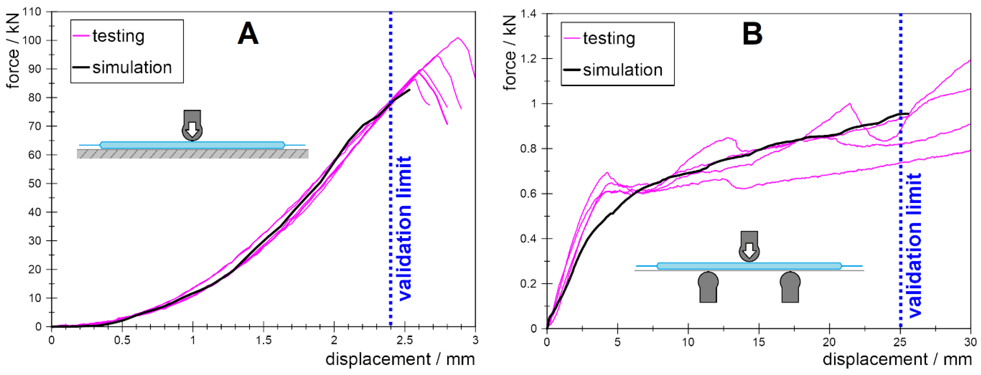
3. Validated Cell Model

This section expounds upon the procedural framework utilized in constructing a mechanically validated model of a lithium-ion battery pouch cell, specifically of type NMC811, incorporating virtual short circuit detection capabilities. Particular attention is directed towards validating the cell’s performance along the out-of-plane direction. Findings derived from mechanical testing serve as the foundational basis for construction of the finite element simulation model and formulating the criteria for short circuit detection.

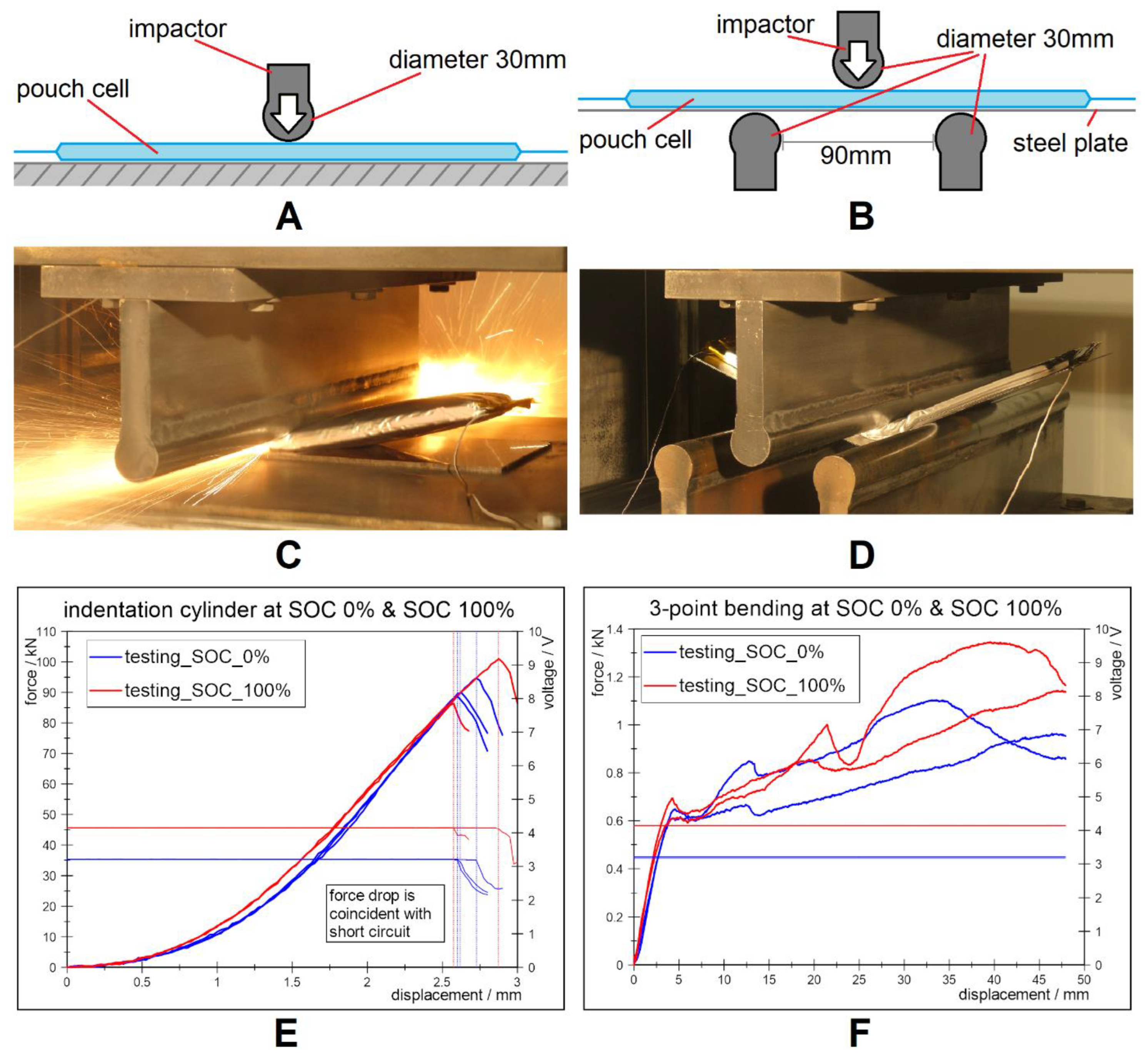
3.1. Mechanical Testing of Pouch Cells

Experimental procedures encompassed two distinct quasi-static load cases executed at varying states of charge (SOC), outlined in Table 2. Due to resource limitations, experimental efforts were primarily directed towards assessing out-of-plane behaviors. Given the typical longitudinal mounting orientation of battery modules in vehicles, the out-of-plane direction of pouch cells aligns with the vehicle’s sides, rendering side impacts, particularly side-pole collisions, crucial load scenarios for battery systems. Accordingly, testing employed a cylindrical impactor simulating side pole crash scenarios [41]. All tests were conducted under quasi-static conditions. Quasi-static testing is much simpler and cheaper than dynamic testing, but there are differences in the force characteristics [42,43]. It can represent a worst-case scenario because the energy up to the short circuit is lower, but the force level at the short circuit is higher. At present, only low deformation rates are to be expected anyway, since EV-batteries are heavily shielded.
In the indentation cylinder load case, the cell was positioned on a fixed even ground and subjected to crushing by a cylindrical impactor until either short circuit detection or surpassing a predetermined force threshold. In the 3-point bending load case, the cell was placed on a 1-mm-thick metal sheet, suspended via two steel cylinders on either side. The advancing cylinder was halted upon short circuit detection or exceeding a specified impactor displacement threshold. The metal sheet emulates the mounting configuration within the module/pack and substitutes neighboring cell support and surrounding components. Figure 1A,B illustrate both testing methodologies.
Throughout the tests, measurements encompassed impactor force, impactor displacement, and cell voltages, with voltage drops serving as indicators of internal short circuits. Tests were recorded, and pre- and post-test photographs were taken for documentation purposes. Figure 1C–F displays the results of all indentation cylinder and 3-point bending measurements.
Analysis of the force-displacement curves from the indentation cylinder tests reveals consistent behavior across all five tests, with higher forces observed for charged cells, attributed to state-of-charge-dependent interface behavior between the anode coating and current collector [19]. Short circuit events coincided with significant force drops corresponding to electrode stack failure, consistent with findings in the literature [44]. Short circuit initiation occurred at displacements ranging from 2.6 mm to 2.9 mm with no clear trend regarding charged and uncharged cells.
The force-displacement curves from the four 3-point bending tests exhibit notable dispersion following the initial force rise to 0.6 kN, a phenomenon unprecedented in prior studies. Probable causes include frictional effects such as adherence and slippage coupled with slight specimen warpage. Warpage of cells happened during the process of harvesting them from complete battery modules. Buckling of cells and delamination within the electrode stack during deformation could also contribute to the observed dispersion. Because of the observed force spread and the presence of a supporting steel plate, no SOC dependency on short circuit occurrence could be inferred or dismissed. Notably, short circuit events did not manifest in any cell during tests, even at the maximum impactor displacement of 50 mm.

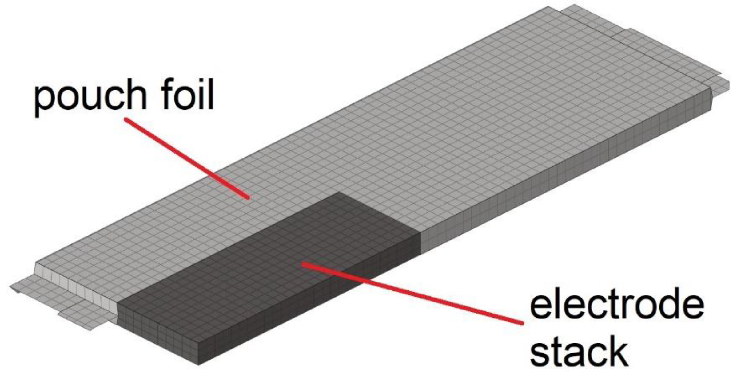
3.2. FE Model of Pouch Cell

Employing a macro-mechanical simulation methodology [45], the construction of the finite element model for the battery cell was executed. This approach circumvents the explicit representation of individual thin layers of electrodes and separators within the electrode stack. Instead, the entire electrode stack is represented as a single solid component with aggregate properties. The FE model of the pouch cell is depicted in Figure 2.
Figure 3 illustrates the comparative analysis between the final simulation results and the experimental testing results.
For the load case of indentation cylinder, a validation limit of 2.4 mm is established, ensuring a safety margin of 10% below the initial occurrence of short circuit. Conversely, for the 3-point bending load case, a more liberal validation limit of 25 mm is set, deemed adequate to encompass the pertinent deformation range encountered during testing of complete battery modules. The results demonstrate excellent agreement between the mechanical properties of the simulation model, incorporating an optimized cell stack material, and the experimental data.
Furthermore, the standalone testing of the aforementioned steel sheet in a 3-point bending configuration facilitated the development of a validated mechanical model for the metal sheet. This model was subsequently integrated into the 3-point bending simulation of the cell tests. In the interest of brevity, the testing and simulation data pertaining to the metal sheet are omitted from this publication.

3.3. Virtual Short Circuit Detection

Virtual short circuit detection is conducted during the postprocessing stage of the finite element simulations. As illustrated in Figure 2, the electrode stack model comprises solid elements. Throughout the deformation process, these elements experience mechanical strains [10,15,46], which can serve as indicators for virtual short circuit detection. Various alternative approaches utilize different physical quantities such as mechanical stresses [45], force [47], or geometric factors [48]. In the case presented, von Mises equivalent strain emerges as a suitable parameter for short circuit detection. This parameter is computed using the formula
ε E q u = 2 3 ε x 2 + ε y 2 + ε z 2 + 1 2 ε x y 2 + ε y z 2 + ε z x 2
where εx, εy, εz, εxy, εyz and εzx represent the components of the strain tensor. These strain values, recorded for individual electrode stack elements during simulation, form the basis for calculating the von Mises equivalent strain values.
Despite the orthotropic characteristics of cell mechanical behavior, the von Mises equivalent strain criterion proves efficacious in this specific context. Notably, model calibration is restricted to a single loading direction perpendicular to the electrodes, necessitating potential adaptations of the applied short circuit criterion for more complex loading scenarios.
During postprocessing, the von Mises equivalent strain of each element in the electrode stack is analyzed for every time step. At the displacement correlating to the internal short circuit point, as identified in physical load case indentation cylinder tests, the maximum equivalent strain of a single electrode stack element reaches 0.248. This value is validated through the 3-point bending load case simulation, where this threshold is never exceeded, indicating no short circuit events, matching the outcome of the physical tests. Thus, it is established as the viable threshold value for the short circuit criterion.
The method allows for pinpointing of the initiation of a short circuit to a single solid element of the simulated electrode stack. This location is also the point where a hot spot would form in the early stage of a thermal runaway event.

4. LIB Module

Section 3 outlines the methodology employed in creating a mechanically validated FE pouch cell model, incorporating virtual short circuit detection. The utilized approach is extensively documented and well-established in the literature [13,14,15,16,17,18,19]. This FE cell model serves as the cornerstone for constructing the LIB module model, given that the module comprises several identical cells. Its construction involves integrating geometry and material data of all supplementary module components. Quality assessment of the FE simulation model is contingent upon comparison with physical test results, thereby ensuring its accuracy and reliability.

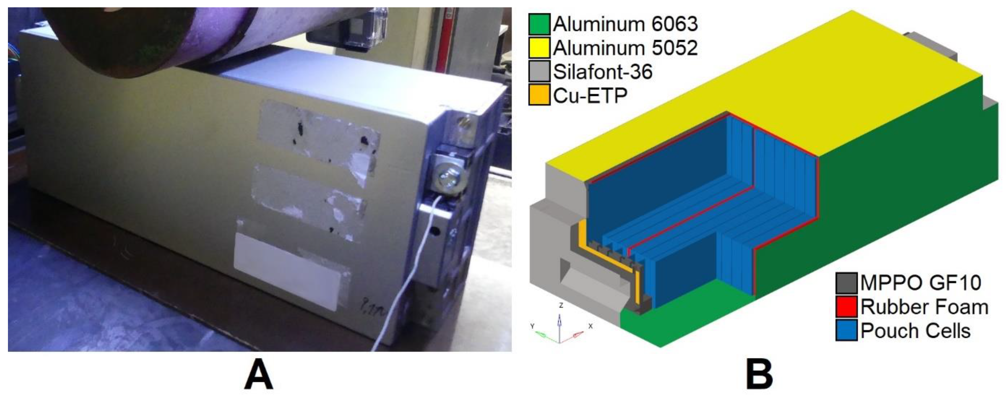
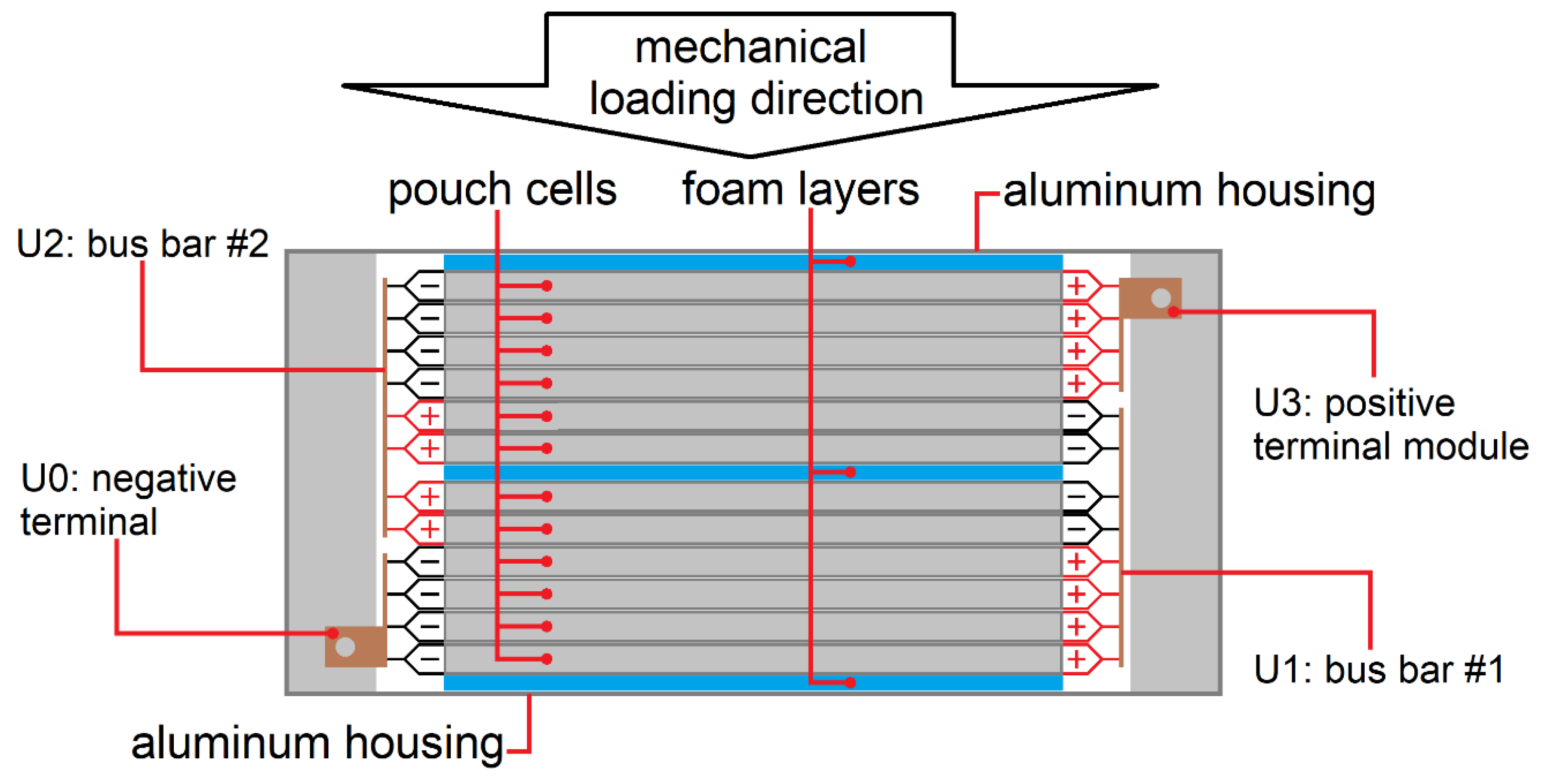
4.1. FE Model Module

The formulation of material models for module components relies on data compiled from the existing literature sources. Table 3 provides a comprehensive overview of these materials.
The 3D geometry of the FE model is derived from measurements obtained from original module parts. Figure 4 illustrates the original module alongside its corresponding FE model.
Integration of the module components with the finalized FE model of the pouch cell (detailed in Section 2) yields the finished module simulation model. Table 4 enumerates the properties characterizing the complete module model.

4.2. Mechanical Tests of Battery Modules

The verification of the LIB module simulation model is conducted through a series of physical tests, with testing parameters outlined in Table 5.
These tests are conducted under quasi-static conditions, involving low impactor velocities. Positioned on rigid ground, the battery module undergoes compression via a cylindrical impactor with a diameter of 150 mm until short circuit detection occurs. The adoption of a cylindrical impactor conforms to established norms within the realm of crash safety [55]. Notably, the module comprises twelve interconnected cells, arranged in a configuration of four cells in parallel and three cells in series, as illustrated in Figure 5.
Schematic representations indicate the four points of voltage measurement, denoted as U0, U1, U2, and U3. Accessibility to these measurement points is facilitated through integrated sockets within the battery module. Voltage signals are designated according to Table 6, with V3 representing the voltage of the upper four cells closest to the impactor, V2 signifying the voltage of the middle four cells, and V1 indicating the voltage of the lower four cells.

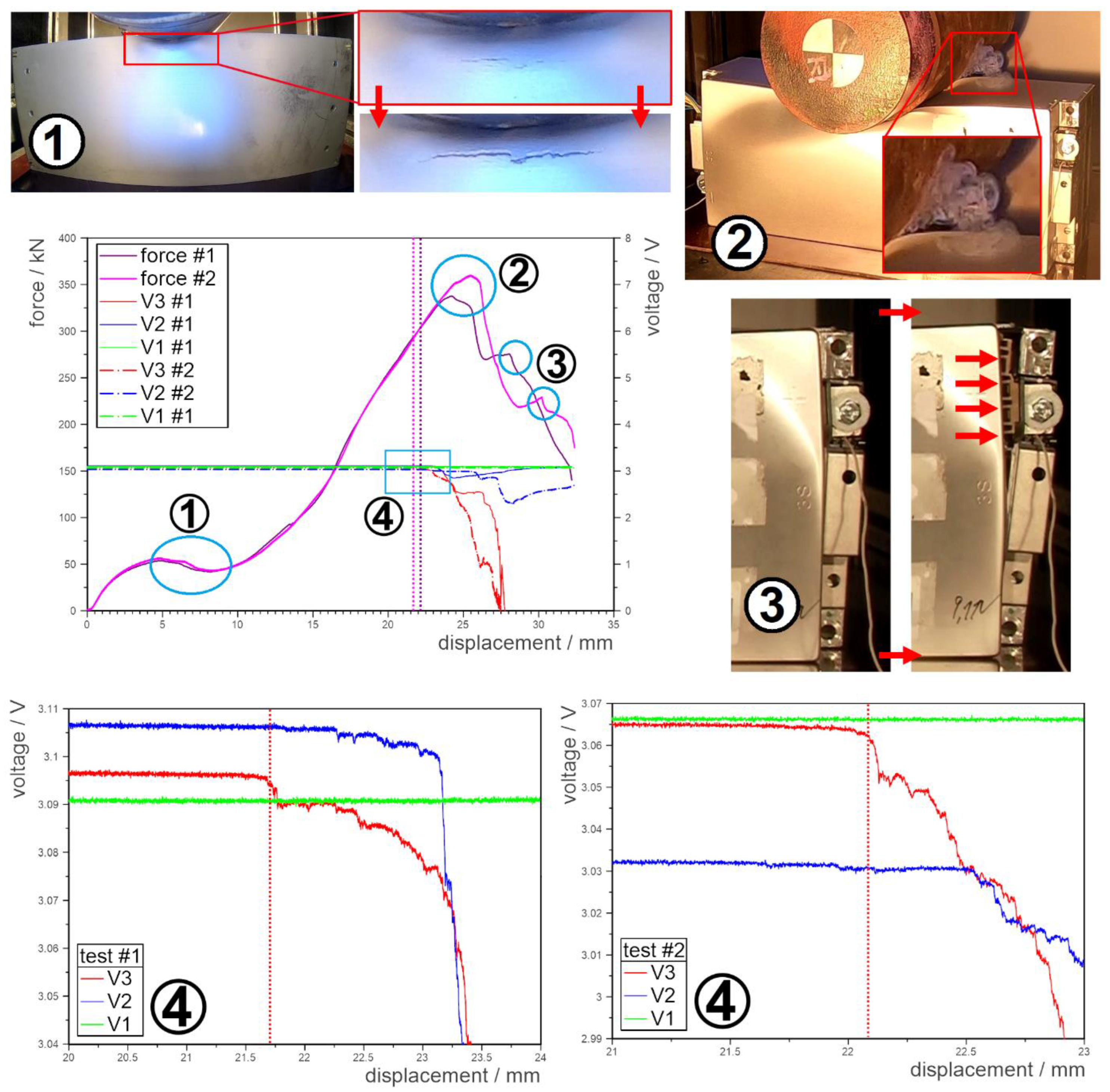
5. Generation of Validation Data

The mechanical testing results for the LIB modules are depicted in Figure 6.
The force-displacement curves from these tests show an initial increase in force up to 50 kN, followed by a minor decline at point 1. In this initial phase, the module housing is the primary component resisting deformation. With the modules positioned on their sides, the forces are channeled through the lid (1.2 mm thick) and mainly through the bottom plate (3.2 mm thick), both made from aluminum alloys (refer to Table 3). At this stage, the pouch cells offer minimal resistance as they are sandwiched between three foam layers (each 3 mm thick, totaling 9 mm, as visible in Figure 5). These foam layers compress before any deformation of the cells occurs. The force drop observed at point 1 is attributed to the buckling and cracking of the bottom plate, as verified using video footage. Subsequently, forces rise to peak values of around 340 kN for test #1 and 360 kN for test #2.
During this phase, the cells are compressed, and the hull components experience further deformation. At point 2, a second force drop occurs as the pouch cells rupture, as indicated by smoke emissions from the module, even though the tests were conducted at 0% SOC. Post-test analysis revealed broken cells (Figure 7A), their halves being displaced to the module’s sides.
At point 3, a brief force increase is followed by another decline, attributed to the rupture of welding seams on the casing’s narrow sides, causing the module to split open, as visually confirmed in the videos. The interior components are pushed in the direction of these openings, leading to a continued force reduction. The graphs marked as 4 provide close-ups of the voltage curves, which are also visible in the main graph. In both tests, the initial voltage drop was recorded for signal V3, representing the voltage of the top four cells connected in parallel. The impactor displacements and forces at the short circuit were 21.7 mm and 294 kN for test #1 and 22.1 mm and 303 kN for test #2.
Due to the limited availability of specimens, only two module tests were performed which is why a statistical error can not be calculated. However, the authors have great confidence in the reliability of the presented measurement results. The test rig features a calibrated load cell and direct measurement of displacement which is corrected with the test rig’s own stiffness. This minimizes the systemic failure of the measurement. Details are shown in Section 2.1.
Analyses of the deformed specimens reveal significant damage to the cells, as depicted in Figure 7. Notably, half of the cells were torn apart, creating a distinct gap, while the remaining cells exhibited no damage. This failure pattern, characterized by the shearing of all layers in the electrode stack, is well documented in the existing literature [44] and has been successfully replicated in simulations [56]. In this case, the six failed cells formed a compact unit, glued together on their flat sides using double-sided tape with an unknown adhesive, covering 30% of the cell surface and applied centrally. This adhesive likely facilitated the transmission of the failure pattern through all six cells, terminating at the foam layer in the middle of the module. The smooth decline in force after failure (Figure 6, between points 2 and 3), occurring at deformations greater than those at short circuit, indicates a simultaneous failure rather than a stepwise one.
Further module disassembly, including busbar removal, allowed for individual voltage measurements of the lower six cells, which all showed initial voltages and no short circuits. This correlates with the V2 measurements, which represent the four middle cells—two torn apart and two intact—resulting in a voltage drop followed by a recovery to the original value. This suggests that an initial short circuit in the damaged cells, followed by further deformation separating the cell halves, restored the voltage to the value of the intact cells. Figure 7B depicts the LIB module simulation model, showing deformed pouch cells at a similar deformation level to that in Figure 7A, but without fracturing, highlighting the model’s limitation in predicting cell fracture.
In single-cell testing (Figure 1A), a short circuit always coincides with a force drop due to cell fracture. However, in the module tests, the short circuit occurs significantly before the force drop. A plausible explanation for this discrepancy is that in single cells, the initial failure of a cell layer, combined with the test rig’s inertia, triggers a cascade effect that tears through the entire cell. Conversely, in the module, the loading scenario differs, with additional deformable cells inducing bending rather than just compression as seen in single-cell tests.

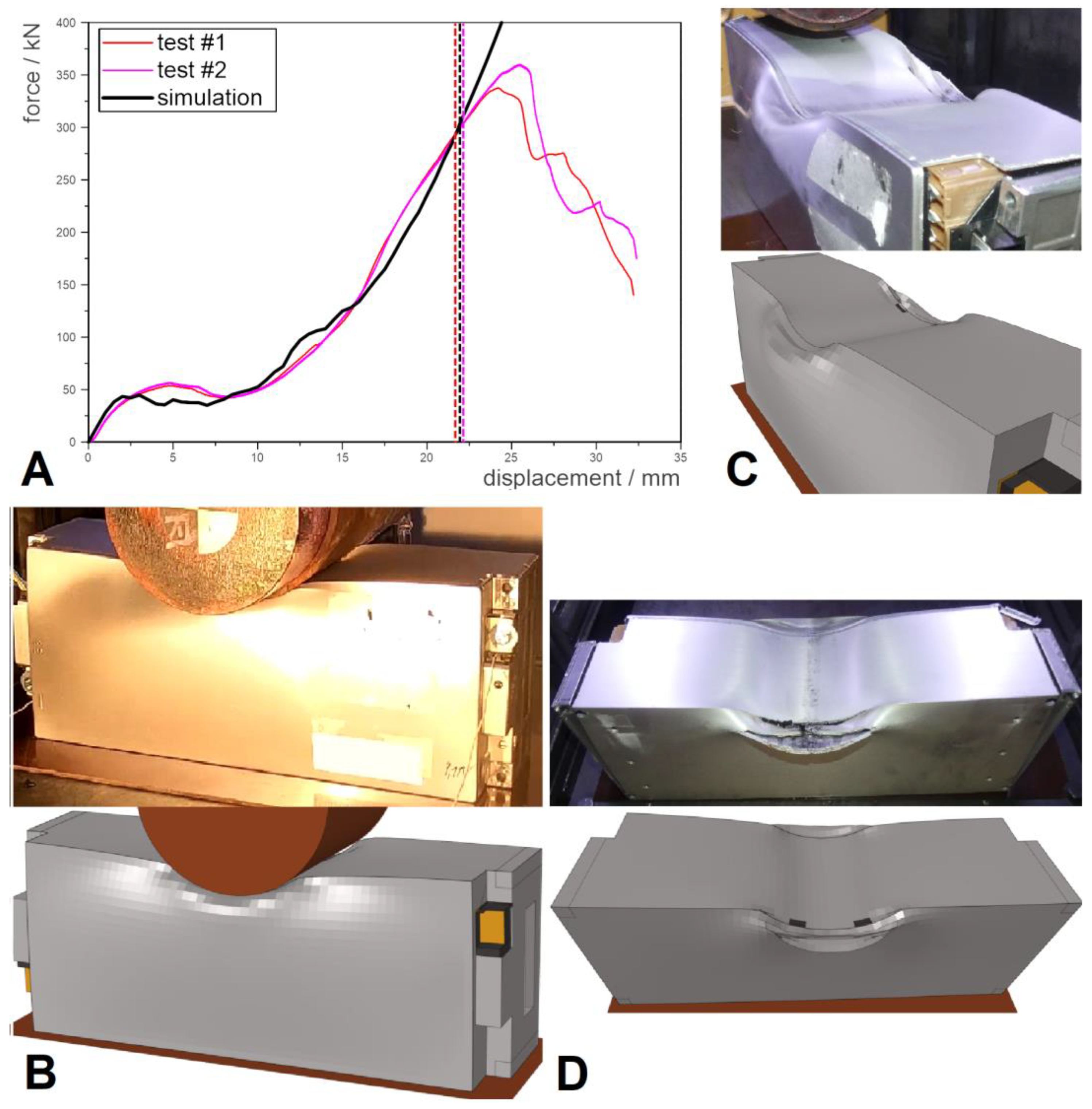
6. Results of Module Simulation

In Figure 8, the results of the battery module simulation are compared with those from high-precision mechanical module tests.
The force-displacement curves from the simulation closely align with the experimental results up to the point of short circuit (Figure 8A), which serves as the validation limit. The simulation does not capture the force drop corresponding to the breaking of the electrode stacks (~26 mm impactor displacement) because the electrode stack model does not incorporate mechanical failure. The postprocessing method for virtual short circuit detection described in Section 2.3 identified the first short circuit in the uppermost cell, closest to the impactor. At an impactor displacement of 22.0 mm, one finite element of this cell’s electrode stack reached a von Mises equivalent strain of 0.2461, exceeding the threshold and indicating an internal short circuit in the simulation. In comparison, the impactor displacements at short circuit for the tests were 21.7 mm and 22.1 mm, with corresponding forces of 294 kN and 303 kN, respectively, against 306 kN in the simulation.
The deformation patterns are also compared (Figure 8B–D). Image B shows the module in the test setup at the end of deformation, while images C and D show the module after testing and impactor removal, revealing the area of severe deformation. Image D shows the partially fractured bottom plate of the module, which the simulation accurately reproduces.
The overall comparison of force-displacement curves, short circuit behavior, and deformation patterns demonstrates that the simulation closely replicates the mechanical test results.

7. Conclusions

7.1. Methods

The established method of quasi-static high-precision testing, combined with a macro mechanical simulation approach [13], was employed to develop a finite element simulation model of a LIB pouch cell, valid for out-of-plane mechanical behavior. This modeling approach extends the applicability of the cell model up to the vehicle level. This modeling strategy allows for the application of the cell model at the vehicle level. Additionally, a von Mises equivalent strain-based criterion for virtual short circuit detection was established, demonstrating functionality through comparison with single-cell testing and simulation results.
This validated cell simulation model was subsequently integrated into a higher assembly level to simulate a complete LIB battery module containing twelve cell models. Surrounding parts were modeled using material properties from the available literature and geometric data obtained from module and component measurements.
Mechanical tests on actual LIB module specimens were conducted to evaluate the accuracy of the module simulation model. The comparison with high-precision test results showed that the simulation accurately reproduced short circuit behavior and mechanical responses, including the force-displacement curve, force at the first short circuit, and deformation patterns.

7.2. Results

This mechanical LIB module simulation model is, to the authors’ knowledge, the first to combine a validated virtual short circuit detection method for selected load cases with a mechanical model. Short circuit is detected in a single element, the position of which marks the hot spot in a thermal runaway event. A significant advantage of this model is its meso-mechanical approach, which enables fast calculations. The minimum calculation timestep surpasses that of current full vehicle crash models, and the model’s element and node count prevent ID conflicts. This allows for duplication and application in simulations of complete battery packs and even full electric vehicles.

7.3. Outlook

Unlike traditional mechanical crash modeling of vehicle batteries, this approach offers better resolution of individual cells, which is essential for future scenarios that require allowing small battery deformations while avoiding internal short circuits during crashes.
In future work, this module model will be used within a multi-physics simulation environment to estimate the thermal consequences of mechanically induced short circuits. This multi-physics environment aims to evaluate whether thermal runaway propagation can be mitigated through appropriate measures despite mechanically induced thermal runaway in a single cell.

Author Contributions

Conceptualization, C.B. and H.K.; methodology, C.B., A.M. and K.J.; software, K.J.; validation, K.J. and A.M.; formal analysis, K.J.; investigation, K.J. and A.M.; resources, H.K.; data curation, K.J. and A.M.; writing—original draft preparation, K.J.; writing—review and editing, H.K., C.B. and K.J.; visualization, K.J.; supervision, C.B.; project administration, K.J.; funding acquisition, H.K. All authors have read and agreed to the published version of the manuscript.

Funding

The project was funded by the program “Mobilität der Zukunft” of the Austrian Federal Ministry for Climate Action (BMK). The publication was written at Virtual Vehicle Research GmbH in Graz, and partially funded within the COMET K2 Competence Centers for Excellent Technologies from the Austrian Federal Ministry for Climate Action (BMK), the Austrian Federal Ministry for Labor and Economy (BMAW), the Province of Styria (Dept. 12) and the Styrian Business Promotion Agency (SFG). The Austrian Research Promotion Agency (FFG) has been authorized for the program management.

Data Availability Statement

The datasets presented in this article are only available to consortium members of the Tristate project and cannot be shared due to contractual arrangements.

Acknowledgments

The authors thank all partners of the Tristate project for their valuable input to this work. The Authors also thank the team of the Battery Safety Test Centre Graz, who performed the mechanical tests for this publication.

Conflicts of Interest

Author Heimo Kreimaier was employed by the company MAGNA STEYR Fahrzeugtechnik GmbH & Co KG. The remaining authors declare that the research was conducted in the absence of any commercial or financial relationships that could be construed as a potential conflict of interest.

References

  1. European Parliament. EU Ban on the Sale of New Petrol and Diesel Cars from 2035 Explained. 2023. Available online: https://www.europarl.europa.eu/news/en/headlines/economy/20221019STO44572/eu-ban-on-sale-of-new-petrol-and-diesel-cars-from-2035-explained (accessed on 9 February 2023).
  2. Sæther, S.R. Mobility at the crossroads-Electric mobility policy and charging. Transp. Res. Part A 2022, 157, 144–159. [Google Scholar] [CrossRef]
  3. Houache, M.S.E.; Yim, C.-H.; Karkar, Z.; Abu-Lebdeh, Y. On the Current and Future Outlook of Battery Chemistries for Electric Vehicles—Mini Review. Batteries 2022, 8, 70. [Google Scholar] [CrossRef]
  4. Huang, Z.; Li, X.; Wang, Q.; Duan, Q.; Li, Y.; Li, L.; Wang, Q. Experimental investigation on thermal runaway propagation of large format lithium ion battery modules with two cathodes. Int. J. Heat Mass Transf. 2021, 172, 121077. [Google Scholar] [CrossRef]
  5. Korthauer, R. Handbuch Lithium-Ionen-Batterien; Springer Nature: Dordrecht, The Netherlands, 2013. [Google Scholar] [CrossRef]
  6. Chombo, P.V.; Laoonual, Y.; Wongwises, S. Lessons from the Electric Vehicle Crashworthiness Leading to Battery Fire. Energies 2021, 14, 4802. [Google Scholar] [CrossRef]
  7. Pierri, E.; Cirillo, V.; Vietor, T.; Sorrentino, M. Adopting a Conversion Design Approach to Maximize the Energy Density of Battery Packs in Electric Vehicles. Energies 2021, 14, 1939. [Google Scholar] [CrossRef]
  8. Kukreja, J.; Nguyen, T.; Siegmund, T.; Chen, W.; Tsutsui, W.; Balakrishnan, K.; Liao, H.; Parab, N. Crash analysis of a conceptual electric vehicle with a damage tolerant battery pack. Extreme Mech. Lett. 2016, 9, 371–378. [Google Scholar] [CrossRef]
  9. Asp, L.E.; Bouton, K.; Carlstedt, D.; Duan, S.; Harnden, R.; Johannisson, W.; Johansen, M.; Johansson, M.K.G.; Lindbergh, G.; Liu, F.; et al. A Structural Battery and its Multifunctional Performance. Adv. Energy Sustain. Res. 2021, 2, 2000093. [Google Scholar] [CrossRef]
  10. Duan, X.; Wang, H.; Jia, Y.; Wang, L.; Liu, B.; Xu, J. A multiphysics understanding of internal short circuit mechanisms in lithium-ion batteries upon mechanical stress abuse. Energy Storage Mater. 2022, 45, 667–679. [Google Scholar] [CrossRef]
  11. Nijman, E.; Buchegger, B.; Böhler, E.; Rejlek, J. Experimental Characterization and Dynamic Modelling of Electrical Cables. SAE Int. J. Adv. Curr. Pract. Mobil. 2022, 5, 888–896. [Google Scholar] [CrossRef]
  12. Zhu, J.; Wierzbicki, T.; Li, W. A review of safety-focused mechanical modeling of commercial lithium-ion batteries. J. Power Sources 2018, 378, 153–168. [Google Scholar] [CrossRef]
  13. Jantscher, K.; Breitfuß, C.; Miklau, M.; Ismail, K.; Dobusch, P. Virtual Detection of Mechanically Induced Short Circuits in a Cylindrical Lithium-Ion Battery Cell Based on Finite Element Simulation. Batteries 2021, 7, 79. [Google Scholar] [CrossRef]
  14. Bulla, M.; Schmandt, C.; Kolling, S.; Kisters, T.; Sahraei, E. An Experimental and Numerical Study on Charged 21700 Lithium-Ion Battery Cells under Dynamic and High Mechanical Loads. Energies 2022, 16, 211. [Google Scholar] [CrossRef]
  15. Jia, Y.; Gao, X.; Mouillet, J.-B.; Terrier, J.-M.; Lombard, P.; Xu, J. Effective thermo-electro-mechanical modeling framework of lithium-ion batteries based on a representative volume element approach. J. Energy Storage 2020, 33, 102090. [Google Scholar] [CrossRef]
  16. Zhu, F.; Zhou, R.; Sypeck, D.; Deng, J.; Bae, C. Failure behavior of prismatic Li-ion battery cells under abuse loading condition—A combined experimental and computational study. J. Energy Storage 2022, 48, 103969. [Google Scholar] [CrossRef]
  17. Logakannan, K.P.; Zhu, F.; Sypeck, D.; Xu, S.; Deng, J.; Kim, S. Testing and Modeling of Vehicle Li-Ion Battery Module with Prismatic Cells under Abuse Conditions. Energies 2023, 16, 1055. [Google Scholar] [CrossRef]
  18. Aiello, L.; Gstrein, G.; Erker, S.; Kaltenegger, B.; Ellersdorfer, C.; Sinz, W. Optimized Nail for Penetration Test on Lithium-Ion Cells and Its Utilization for the Validation of a Multilayer Electro-Thermal Model. Batteries 2022, 8, 32. [Google Scholar] [CrossRef]
  19. Qu, Y.; Xing, B.; Wang, C.; Xia, Y. Simplified layered model of pouch cell for varied load cases: An indentation and three-point bending study. J. Energy Storage 2022, 59, 106476. [Google Scholar] [CrossRef]
  20. Sahraei, E.; Hill, R.; Wierzbicki, T. Calibration and finite element simulation of pouch lithium-ion batteries for mechanical integrity. J. Power Sources 2012, 201, 307–321. [Google Scholar] [CrossRef]
  21. Qu, Y.; Ge, Y.; Xing, B.; Xia, Y.; Zhou, Q. Development of Detailed Model and Simplified Model of Lithium-Ion Battery Module under Mechanical Abuse; SAE Technical Paper 2022-01-7120; SAE International: Pittsburgh, PA, USA, 2022. [Google Scholar] [CrossRef]
  22. Xia, Y.; Wierzbicki, T.; Sahraei, E.; Zhang, X. Damage of cells and battery packs due to ground impact. J. Power Sources 2014, 267, 78–97. [Google Scholar] [CrossRef]
  23. Kalnaus, S.; Wang, H.; Watkins, T.; Simunovic, S.; Sengupta, A. Features of mechanical behavior of EV battery modules under high deformation rate. Extrem. Mech. Lett. 2019, 32, 100550. [Google Scholar] [CrossRef]
  24. Xia, Y.; Chen, G.; Zhou, Q.; Shi, X.; Shi, F. Failure behaviours of 100% SOC lithium-ion battery modules under different impact loading conditions. Eng. Fail. Anal. 2017, 82, 149–160. [Google Scholar] [CrossRef]
  25. Essl, C.; Golubkov, A.W.; Fuchs, A. Comparing Different Thermal Runaway Triggers for Two Automotive Lithium-Ion Battery Cell Types. J. Electrochem. Soc. 2020, 167, 130542. [Google Scholar] [CrossRef]
  26. Kriston, A.; Kersys, A.; Antonelli, A.; Ripplinger, S.; Holmstrom, S.; Trischler, S.; Döring, H.; Pfrang, A. Initiation of thermal runaway in Lithium-ion cells by inductive heating. J. Power Sources 2020, 454, 227914. [Google Scholar] [CrossRef]
  27. Liu, Y.; Zhang, L.; Huang, X.; Hao, M.; Huang, X. Laser-induced thermal runaway dynamics of cylindrical lithium-ion battery. J. Energy Storage 2024, 86, 111337. [Google Scholar] [CrossRef]
  28. Essl, C.; Seifert, L.; Rabe, M.; Fuchs, A. Early Detection of Failing Automotive Batteries Using Gas Sensors. Batteries 2021, 7, 25. [Google Scholar] [CrossRef]
  29. Essl, C.; Golubkov, A.W.; Fuchs, A. Influence of Aging on the Failing Behavior of Automotive Lithium-Ion Batteries. Batteries 2021, 7, 23. [Google Scholar] [CrossRef]
  30. Ledinski, T.; Golubkov, A.W.; Schweighofer, O.; Erker, S. Arcing in Li-Ion Batteries. Batteries 2023, 9, 540. [Google Scholar] [CrossRef]
  31. Lai, W.-J.; Ali, M.Y.; Pan, J. Mechanical behavior of representative volume elements of lithium-ion battery modules under various loading conditions. J. Power Sources 2014, 248, 789–808. [Google Scholar] [CrossRef]
  32. Lai, W.-J.; Ali, M.Y.; Pan, J. Mechanical behavior of representative volume elements of lithium-ion battery cells under compressive loading conditions. J. Power Sources 2014, 245, 609–623. [Google Scholar] [CrossRef]
  33. Zhou, M.; Hu, L.; Chen, S.; Zhao, X. Different mechanical-electrochemical coupled failure mechanism and safety evaluation of lithium-ion pouch cells under dynamic and quasi-static mechanical abuse. J. Power Sources 2021, 497, 229897. [Google Scholar] [CrossRef]
  34. Schmid, A.; Pasquale, A.; Ellersdorfer, C.; Raffler, M.; Champaney, V.; Ziane, M.; Chinesta, F.; Feist, F. Mechanical Characterization of Li-Ion Cells and the Calibration of Numerical Models Using Proper Generalized Decomposition. In Proceedings of the ASME 2023 International Mechanical Engineering Congress and Exposition, New Orleans, LA, USA, 29 October–2 November 2023. IMECE2023-113228. [Google Scholar] [CrossRef]
  35. GTM, Kraftaufnehmer. Kraftsensoren Serie, K. 2024. Available online: https://www.gtm-gmbh.com/fileadmin/08_Downloads/Datenblaetter/Kraftaufnehmer/K/Data_sheet_Series_K.pdf (accessed on 6 February 2024).
  36. Hill, R. Elastic properties of reinforced solids: Some theoretical principles. J. Mech. Phys. Solids 2002, 11, 357–372. [Google Scholar] [CrossRef]
  37. LS-Dyna Keyword User’s Manual-Volume II Material Models. 2023. Available online: https://ftp.lstc.com/anonymous/outgoing/jday/manuals/LS-DYNA_Manual_Volume_II_R11.pdf (accessed on 12 October 2023).
  38. Mises, R.V. Mechanik der festen Körper im plastisch-deformablen Zustand., Nachrichten von der Gesellschaft der Wissenschaften zu Göttingen. Math. Phys. Kl. 1913, 1913, 582–592. [Google Scholar]
  39. Stander, N.; Basudhar, A.; Roux, W.; Witowski, K.; Eggleston, T.; Goel, T.; Graig, K. LS-OPT User’s Manual, Version 6.0; Livermore Software Technology Corp: Livermore, CA, USA, 2019. [Google Scholar]
  40. Stander, N.; Müllerschön, H. Introduction to LS-OPT-Class Notes; Livermore Software Technology Corp: Livermore, CA, USA, 2014. [Google Scholar]
  41. Euro NCAP. Side Pole. 2024. Available online: https://www.euroncap.com/en/car-safety/the-ratings-explained/adult-occupant-protection/lateral-impact/side-pole/ (accessed on 14 February 2024).
  42. Kisters, T.; Gilaki, M.; Nau, S.; Sahraei, E. Modeling of Dynamic Mechanical Response of Li-Ion cells with Homogenized Electrolyte-Solid Interactions. J. Energy Storage 2022, 49, 104069. [Google Scholar] [CrossRef]
  43. Chen, X.; Yuan, Q.; Wang, T.; Ji, H.; Ji, Y.; Li, L.; Liu, Y. Experimental study on the dynamic behavior of prismatic lithium-ion battery upon repeated impact. Eng. Fail. Anal. 2020, 115, 104667. [Google Scholar] [CrossRef]
  44. Zhu, J.; Li, W.; Wierzbicki, T.; Xia, Y.; Harding, J. Deformation and failure of lithium-ion batteries treated as a discrete layered structure. Int. J. Plast. 2019, 121, 293–311. [Google Scholar] [CrossRef]
  45. Greve, L.; Fehrenbach, C. Mechanical testing and macro-mechanical finite element simulation of the deformation, fracture, and short circuit initiation of cylindrical Lithium ion battery cells. J. Power Sources 2012, 214, 377–385. [Google Scholar] [CrossRef]
  46. Liu, B.; Zhang, J.; Zhang, C.; Xu, J. Mechanical integrity of 18650 lithium-ion battery module: Packing density and packing mode. Eng. Fail. Anal. 2018, 91, 315–326. [Google Scholar] [CrossRef]
  47. Sahraei, E.; Campbell, J.; Wierzbicki, T. Modeling and short circuit detection of 18650 Li-ion cells under mechanical abuse conditions. J. Power Sources 2012, 220, 360–372. [Google Scholar] [CrossRef]
  48. Raffler, M.; Sevarin, A.; Ellersdorfer, C.; Heindl, S.F.; Breitfuss, C.; Sinz, W. Finite element model approach of a cylindrical lithium ion battery cell with a focus on minimization of the computational effort and short circuit prediction. J. Power Sources 2017, 360, 605–617. [Google Scholar] [CrossRef]
  49. Total Materia. Aluminum 6063-T6. 2023. Available online: https://www.totalmateria.com/ (accessed on 2 February 2023).
  50. Aerospace Specification Metals Inc. Aluminum 5052-O. 2023. Available online: https://asm.matweb.com/search/SpecificMaterial.asp?bassnum=MA5052O (accessed on 2 February 2023).
  51. Rheinfelden. Technische Informationen Silafont-36. 2023. Available online: https://rheinfelden-alloys.eu/wp-content/uploads/2015/11/TDB_Silafont-36_AlSi10MnMg_DE_V2.pdf (accessed on 2 February 2023).
  52. Batz Burgel. Werkstoffdatenblatt Kupfer: CW004A (Cu-ETP 2.0065). 2023. Available online: https://batz-burgel.com/wp-content/uploads/data-de/BB_CW004A.pdf (accessed on 23 March 2023).
  53. MatWeb Material Property Data. Avient Edgetek MP-10GF/000 Modified PPO-10% Glass Fiber Reinforced. 2023. Available online: https://www.matweb.com/search/DataSheet.aspx?MatGUID=1befaa98cdaf40eeb5a31e3b99034325&ckck=1 (accessed on 2 February 2023).
  54. MatWeb Material Property Data. Kuraray HYBRAR® F3 Foam Compound. 2024. Available online: https://www.matweb.com/search/DataSheet.aspx?MatGUID=fb279f5743694afdb27c78066dd7d6e6 (accessed on 6 February 2024).
  55. Doughty, D.H.; Crafts, C.C. FreedomCAR Electrical Energy Storage System Abuse Test Manual for Electric and Hybrid Electric Vehicle Applications; Sandia National Laboratories: Albuquerque, NM, USA; Livermore, CA, USA, 2006. [Google Scholar] [CrossRef]
  56. Lian, J.; Wierzbicki, T.; Zhu, J.; Li, W. Prediction of shear crack formation of lithium-ion batteries under rod indentation: Comparison of seven failure criteria. Eng. Frac. Mech. 2019, 217, 106520. [Google Scholar] [CrossRef]
Figure 1. (A): testing principle for the load case indentation cylinder; (B): testing principle for the load case 3-point bending; (C): LIB pouch cell at SOC 100% immediately after short circuit during indentation cylinder test; (D): LIB pouch cell during 3-point bending test; (E): force-displacement (solid lines), voltage-displacement (thin lines) and occurrence of short circuit (dotted lines) for the indentation cylinder tests; (F): force-displacement (solid lines), voltage-displacement (thin lines) and occurrence of short circuit (dotted lines) for the 3-point bending tests.
Esa 01 00003 g001
Figure 2. FE model of a LIB pouch cell.
Esa 01 00003 g002
Figure 3. Force-displacement curves for load cases indentation cylinder (A) and 3-point bending (B); pink lines: testing results, black lines: simulation results.
Esa 01 00003 g003
Figure 4. LIB pouch cell module (A) and a sectional view of the FE simulation model (B) of the same module with cells shown in blue and module materials shown in different colors.
Esa 01 00003 g004
Figure 5. Schematic representation of the pouch battery module.
Esa 01 00003 g005
Figure 6. Results gathered from mechanical tests of two LIB module; pictures labeled 1, 2, and 3 show details of the module at different stages during testing; the graphs labeled 4 show a close-up of the voltage measurements from both tests at the point of the first short circuit. Red arrows in picture 1 connect two stills taken from the testing video showing first crack initiation followed by a fully formed crack. Red arrows in picture 1 connect two stills taken from the testing video showing the module lid before and after the failure of a welding seam.
Esa 01 00003 g006
Figure 7. (A): Cut open LIB module after testing. (B): A view inside the LIB module simulation model at the same level of deformation.
Esa 01 00003 g007
Figure 8. Comparison of testing and simulation results; (A) force-displacement curves, with occurrence of short circuit marked with dashed lines; (BD) deformation of the module after testing.
Esa 01 00003 g008
Table 1. Specifications of LIB cells and modules used for testing.
SpecimenLength/mmWidth/mmHeight/mmChemistryAnode LayersCapacity
Pouch cell34210211.5NMC 8113871 Ah
Cell module380152108--12 cells (4 parallel and 3 serial)
Table 2. Parameters for mechanical tests performed on LIB pouch cells.
Load CaseNumber of TestsSOC/%Impactor Velocity/mm/minCondition for Successful TestTest Description
Indentation cylinder306Short circuit or 420 kN forceDeformation through cylindrical impactor
2100
3-point bending2 + 1 failed060Short circuit or 50 mm impactor displacementBending deformation through cylindrical impactor and two cylindrical bearings; cell is supported on a 1.4301 steel plate, size (350 × 150 × 1) mm3
2100
Table 3. LIB module materials and components.
Material NameModule ComponentSimulation Material TypeLiterature Source
Aluminum 6063Side plates and bottom plate*MAT_24 (elasto-plastic material [37])[49]
Aluminum 5052Lid*MAT_24[50]
Silafont-36Cover on narrow sides*MAT_24[51]
Cu-ETPBusbars [52]
MPPO GF10Cell support parts, bus bar covers*MAT_24[53]
Rubber foamFoam layers*MAT_24[54]
Table 4. Properties of the complete battery module simulation model.
Model PropertyValue
Number of elements476.866
Element edge length (range)2.5–6.0 mm
Computation time (16 cores)349 min
Total simulation time25.0 ms
Elemental time step1.28 × 10−4 ms
Table 5. Parameters for mechanical tests performed on LIB modules.
Load CaseNumber of TestsSOC/%Impactor Velocity/mm/minCondition for Successful TestTest Description
Indentation cylinder2060Short circuitCylindrical impactor 150 mm diameter
Table 6. Voltage signals for module testing.
Voltage SignalCellsPoints for Measurement
V1Lower 4 cellsU0 and U1
V2Middle 4 cellsU1 and U2
V3Upper 4 cellsU2 and U3
Disclaimer/Publisher’s Note: The statements, opinions and data contained in all publications are solely those of the individual author(s) and contributor(s) and not of MDPI and/or the editor(s). MDPI and/or the editor(s) disclaim responsibility for any injury to people or property resulting from any ideas, methods, instructions or products referred to in the content.

