Article

A Conceptual Design of Deployable Antenna Mechanisms

1
Department of Smart Air Mobility, Korea Aerospace University, Goyang 10540, Republic of Korea
2
Department of Mechanical and Aerospace Engineering, Korea Aerospace University, Goyang 10540, Republic of Korea
3
Satellite System Team 1, Hanwha Systems, Yongin 17121, Republic of Korea
4
Department of Autonomous Vehicle Engineering, Korea Aerospace University, Goyang 10540, Republic of Korea
*
Authors to whom correspondence should be addressed.
These authors contributed equally to this work.
Aerospace 2024, 11(11), 938; https://doi.org/10.3390/aerospace11110938
Submission received: 17 October 2024 / Revised: 7 November 2024 / Accepted: 8 November 2024 / Published: 12 November 2024
(This article belongs to the Special Issue Space Mechanisms and Robots)

Abstract

:
Over the last decade, large-scale antennas have been developed to enhance precise blue force tracking and improve situational awareness. In general, such large-scale antennas, ranging from 1 to up to 10 m, need a specific mechanism that can reconfigure their shapes and morphologies, resulting in stowing and deploying upon the given environment. In parallel, it must be noted that such deployable mechanisms should accommodate a large aperture diameter while ensuring they are lightweight, robust, and structurally rigid to avoid undesired deformations due to the deployment. With these in mind, this work presents a large frustum-shaped deployable antenna mechanism with a large aperture diameter of 7.5 m. The deployable mechanism is composed of hierarchical bayes the radial direction at 30° intervals. Twelve bayes in total identify the overall morphology of the deployable antenna, which features a dodecagon. Specifically, the bay is composed of three linkage structures: a six-bar linkage mechanism, a V-folding mechanism, and a single pantograph mechanism. As a result of static and dynamic simulations, it is identified that the mechanism achieves an area-to-mass ratio of 5.003 m2/kg and a safety factor of 323.8 upon deployment. Conclusively, this work demonstrates a strong potential of the deployable antenna mechanism, providing high rigidity and large aperture diameter while ensuring high stability in space environments.

1. Introduction

The development of large-scale deployable reflectors at has emerged as an interesting research topic due to their strong potential in enabling precise blue force tracking while empowering situational awareness [1,2,3]. Over the years, such deployable reflectors have been generally exploited to remote communication with ground stations on Earth by attaching them to satellites [4,5,6]. It is widely known that the larger aperture diameters of the reflector the better they are in terms of high resolution and performance to acquire images, data, etc., as reported in [7,8]. However, given that the payload of the launching vehicle is limited, it must be highlighted that deployable and/or reconfigurable mechanisms are necessary to allow them to stow at the payload and deploy into a large aperture area at the target orbit [9,10,11,12]. In particular, the flatness of the reflector is an important evaluator to accommodate necessary performances, such as high antenna gain. In this view, the antenna must possess high structural rigidity.
With these considerations in mind, pioneering studies on deployable antenna mechanisms have been demonstrated [11,13,14,15]. In [13,14,16], Astromesh I and II proposed a variety of deployable mechanisms, taking key design parameters into account (e.g., arrangement of joints along diagonal direction, interlocking gear, synchronization mechanism, etc.). In general, such mechanisms can exhibit high deployment ratio; specifically, they achieved a deployment ratio of 10 compared to the aperture at the stowed phase, which is suitable for accommodating large-scale reflectors ranging from 4 m to 50 m. Due to these factors, it is possible to recognize a wide spectrum of frequencies, up to the Ka-band (26.5 to 40 GHz). The Astromesh represents a deployable mechanism utilizing ring-truss structures, which ensures structural stability by incorporating both hierarchical unit frames at the top and bottom and battens to engage the unit frames [16]. Moreover, it is worth noting that the linkages along the diagonal direction play a vital role in ensuring high structural rigidity, which has been widely addressed in truss structures [17,18]. Despite such promising mechanical characteristics, the structural stability and rigidity of the Astromesh can be ensured in a quasi-static state, which corresponds to the neglect of dynamic conditions. Namely, the Astromesh could suffer from unstable dynamic characteristics, because each unit frame operates independently.
To address this, a particular mechanism enabling each unit frame to deploy with identical displacement has been addressed. In [19], Fu et al. achieved a synchronized deployment of each frame unit by employing, for example, gears, cables, and precision joints. Nonetheless, these mechanical components induce the overall weight increase, resulting in constraints, e.g., making them unsuitable for stowing in the payload. In particular, it must be noted that the presence of the mechanical components introduced leads to poor rigidity upon vibration, given the launch environment [20]. Moreover, the presence of the longeron linkage (along the horizonal direction), which defines the aperture diameter of the overall mechanism, determines the configurations upon stowage and deployment, based on the rotation angle of the longeron linkage. As a result, the height of the stowed mechanism increases, making it challenging to accommodate within the payload of the launching vehicle. On the other hand, as the height of the longeron decreases, the deployment ratio reduces.
Meanwhile, Datashvili et al. presented a deployable mechanism in the form of the ring-truss structure, employing a double-shifted pantograph mechanism [21]. This mechanism allows for the height of the reflector structure to be reduced by half while achieving the same deployment ratio as conventional systems, and it ensures stable dynamic characteristics by deploying the unit components with identical displacements. However, challenges remain in achieving lightweight design due to the necessity of additional power sources for deployment.
In a nutshell, the development of large-scale deployable antennas using pantograph mechanisms should break through the following challenges: (1) the necessity of additional constraints and auxiliary power sources to ensure stable operation, which makes it difficult to reduce the overall weight; (2) the structural vulnerability of the ring-shaped structure, which becomes more pronounced as the deployment ratio increases.
With these findings in mind, this work presents a conceptual design of conical frustum-shaped deployable antenna mechanisms that ensure that the synchronized displacements at each node are lightweight and suitable for the payload or the launch vehicle at the stowage stage. The presented deployable antenna is hierarchically composed of twelve bays, each bay containing three mechanisms: a V-folding mechanism, a six-bar linkage mechanism, and a single pantograph mechanism. The folding mechanism is designed to ensure the rigidity of the node where the mesh antenna is installed, which has a lightweight structure with minimal components. Upon full deployment, the V-folding mechanism creates a ring structure that provides rigidity against loads along the horizontal and radial directions. The six-bar mechanism is employed, which acts like the power source, resulting in the deployment. By exploiting the conical frustum morphology, the 6-bar mechanism achieves both high rigidity and a high deployment ratio. Finally, a single pantograph mechanism is incorporated to ensure synchronized dynamic characteristics, allowing each unit frame of the deployment mechanism to extend with identical displacement. Ultimately, through multibody dynamic analysis, the proposed mechanism is demonstrated to evaluate its mechanical characteristics, including deployment ratio, area-to-weight ratio, and synchronized dynamic performance.

2. Materials and Methods

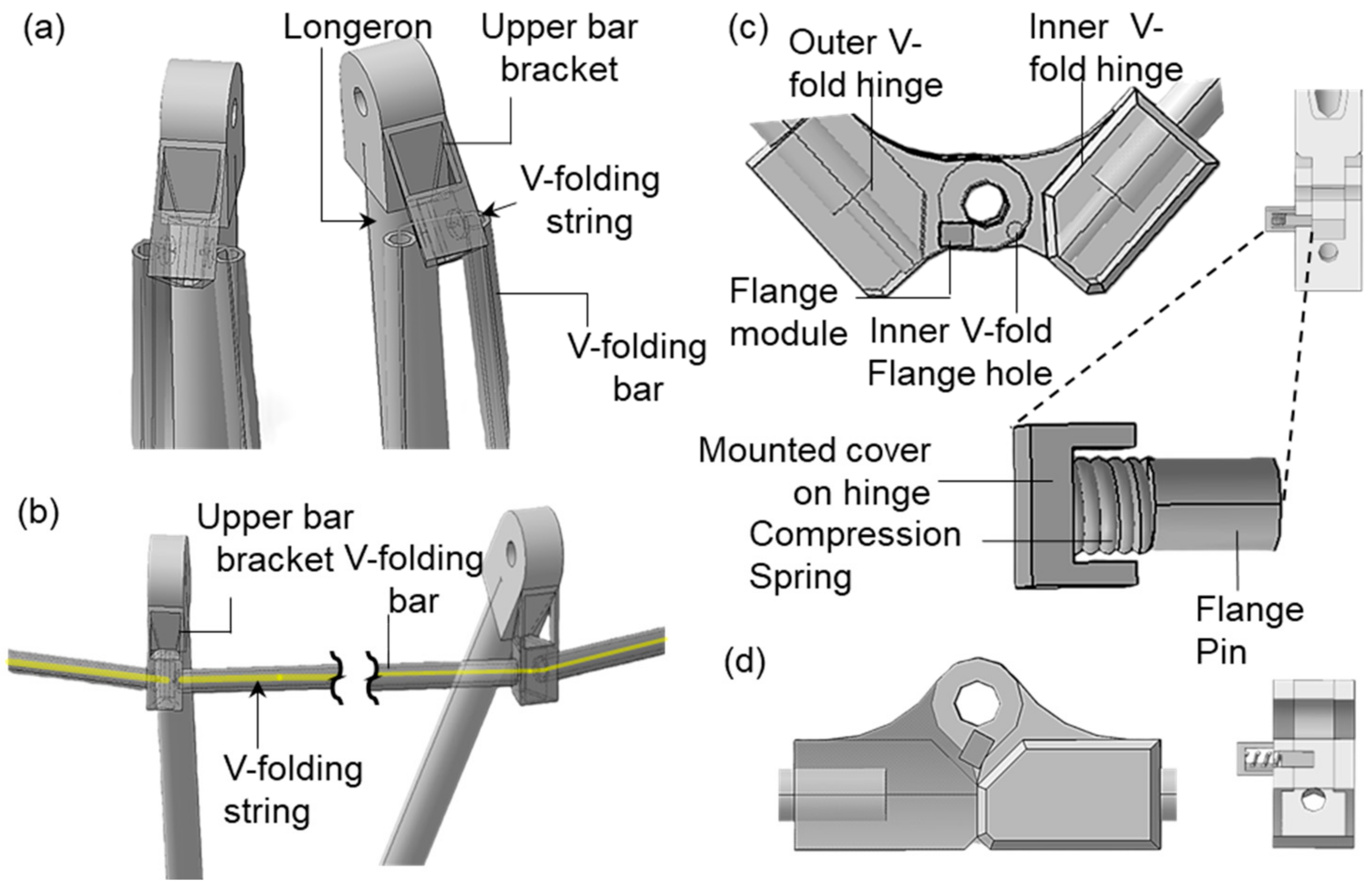
2.1. A Conceptual Design of the Deployable Antenna Mechanism

Figure 1a shows sequential images of when the proposed deployable antenna mechanism moves from the stowed to the deployed stages. As depicted in Figure 1b,c, the deployable antenna mechanism hierarchically consists of (1) a 6-bar linkage mechanism that connects these two mechanisms, resulting in the deployment, (2) a single pantograph mechanism that forms the lower ring, and (3) a V-folding mechanism that forms the upper ring.

Working Principle

The V-folding mechanism plays a role in supporting both the 6-bar linkage mechanism and the upper net fixed point while avoiding undesired movements by moving the longeron linkage (which is folded in a V-shape at the stowage stage) into a horizontal position while deployment. The 6-bar linkage mechanism serves as the driving mechanism. The single pantograph mechanism and the 6-bar linkage mechanism are connected at the bottom net fixed joint, operating independently in two planes: the yz plane and the xz plane, respectively. As will be detailed later, the linear movement of the driving joint of the 6-bar linkage mechanism along the z-axis causes the connected links and joints to move accordingly, initiating the deployment of the mechanism at the stowed stage. The single pantograph mechanism is composed of two links that are mutually connected by a single rotational joint. As the joint of the 6-bar linkage mechanism moves, the two links rotate around the rotational joint, leading to a variation in the height along the z-axis. This synchronized motion results in the full deployment of the mechanism.

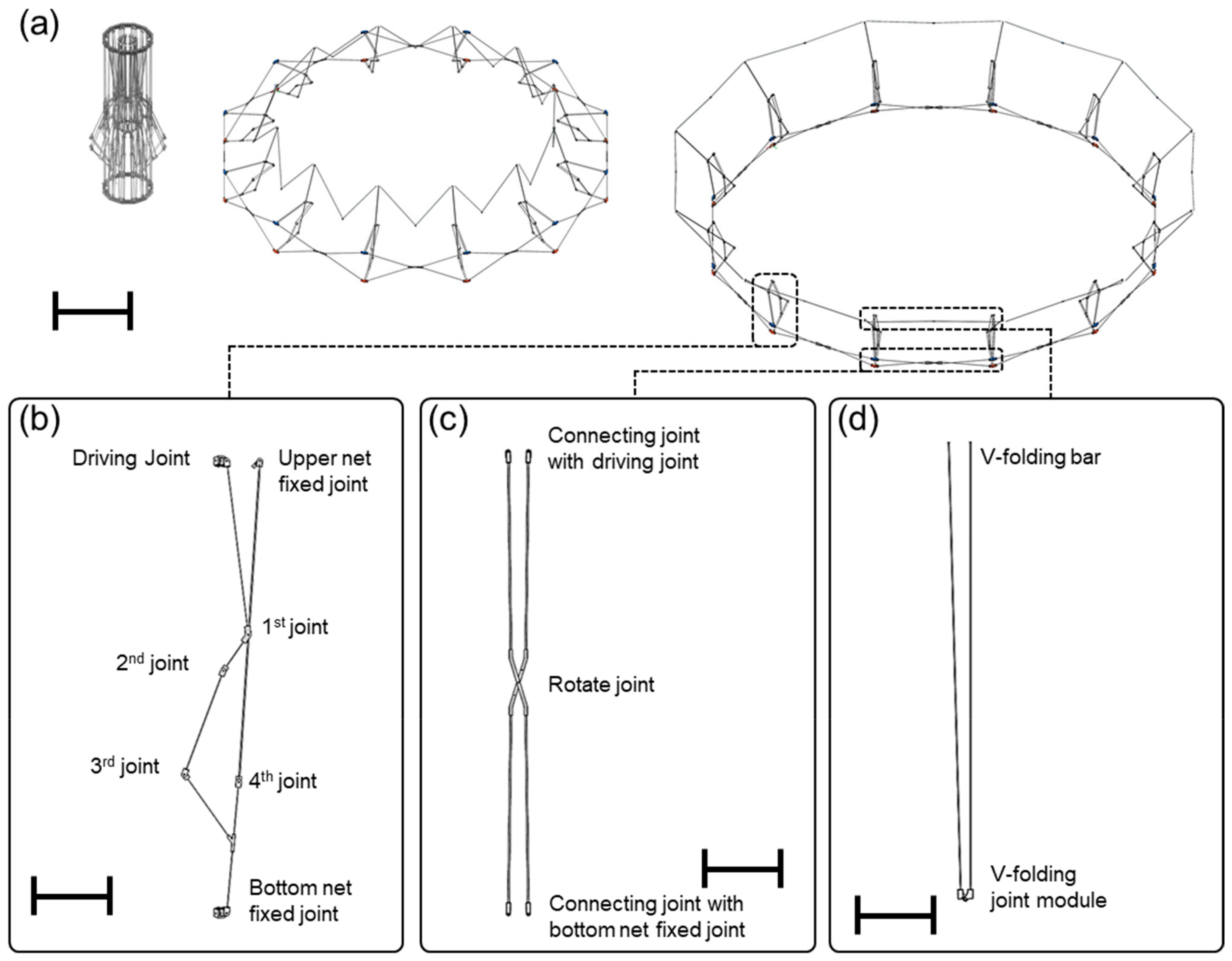
2.2. Hierarchical Composition—Twelve Bays Composed of Three Mecahnisms

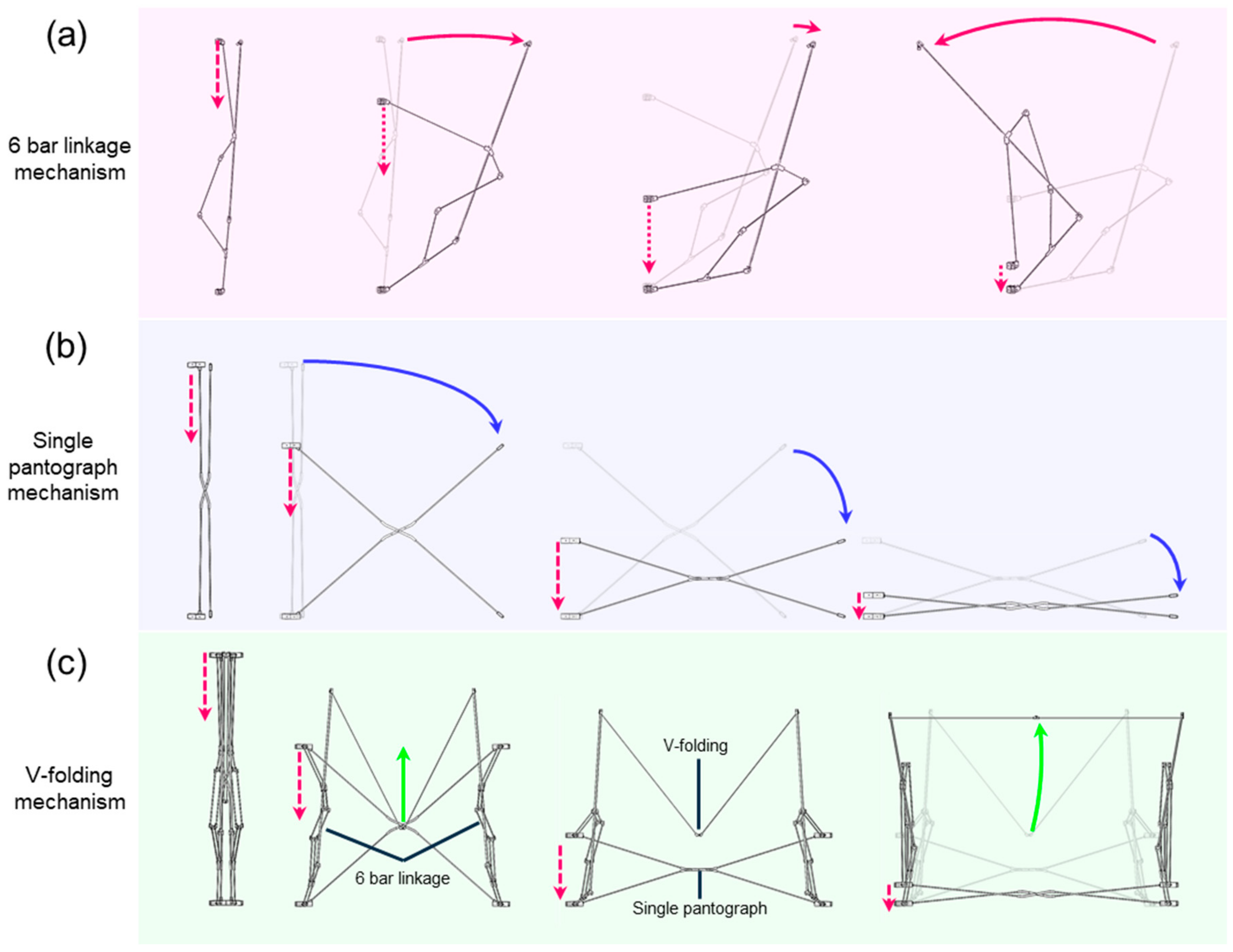
2.2.1. Six-Bar Linkage Mechanism

The 6-bar linkage mechanism consists of six joints and links, acting both as actuators driving the deployment mechanism and as a batten connecting the top and bottom nodes within a single bay. As depicted in Figure 2a, the 6-bar linkage mechanism allows the entire structure to exhibit one degree of freedom in movement by engaging both the single pantograph and the V-folding mechanism. The upper and bottom net fixed joints serve as the longeron that connects the upper and lower rings of the reflector. In the configurations of links, the driving joints and bottom net fixed joints are coupled with the pantograph mechanism. This design allows the linkage configuration to move in a manner similar to a slider-crank mechanism. Due to the difference in the lengths of the linkages, the upper net fixed joint can move to generate an inclined motion. Additionally, the driving joint is constrained to unidirectional motion, resulting in a linear movement along the y-axis. Thus, once all 12 bays are connected, creating a ring shape, it is then possible to determine the degree of taper in the conical frustum shape of the deployable antenna structure.

2.2.2. Single Pantograph Mechanism

The single pantograph mechanism is composed of two links and one joint, as depicted in Figure 2b. It is connected to the joints located at the top and bottom parts of the 6-bar linkage mechanism, and constrains the degrees of freedom of the two links attached to the 6-bar linkage mechanism. The single pantograph mechanism is passively moved by the 6-bar linkage mechanism. Similar to a double pantograph, the folding ratio of the pantograph is determined by its initial height. Specifically, the higher the initial height, the greater the folding ratio of the structure due to inherent characteristics of the pantograph mechanism. In our approach, to achieve weight reduction, a single pantograph mechanism at the bottom of the entire structure is employed.
To obtain the synchronized operation (where the displacement of each bay moves uniformly), each mechanism should be constrained to a single degree of freedom (DOF = 3 n L 1 2 n J ). Although the 6-bar linkage mechanism, composed of six joints and linkages, is capable of three degrees of freedom, the two links (driving joint and bottom net fixed joint) connected to the single pantograph mechanism are constrained to move only along the horizontal direction. As a result, the degree of freedom for the bay, composed of the 6-bar linkage mechanism and the single pantograph mechanism, is constrained to one. In parallel, by coupling twelve bays along the radial direction, the morphology of the deployable antenna features a dodecagon via a closed loop.

2.2.3. V-Folding Mechanism

The V-folding mechanism, composed of two longeron linkages and one rotational joint, is designed to ensure the structural rigidity of the deployable mechanism, as shown in Figure 2c. Specifically, the middle section of the V-folding mechanism is constructed with hinges, allowing it to fold into a V-shape. As will be detailed later, CFRP (Carbon Fiber-Reinforced Plastic) is considered for the V-folding mechanism. The linkages (of the V-folding mechanism) made of CFRP are fixed to both ends of the hinge, and an extensible (elastic) cable passes through the interior linkages (see Figure A1 in Appendix A). This cable connects the V-folding unit to the top end of the longeron in the 6-bar linkage. This connection is likely the free end, creating infinite DoFs. Given these aspects, it is worth noting that the joint motion caused by the wire is kinematically similar to the pole shock-cord driving mechanism, in which the wire couples the pipes. This way, it is possible to ensure that the deployment process of the V-folding mechanism (which involves 3D spatial movements) proceeds smoothly without any mechanical interference due to DOF constraints. For these reasons, once the structure is fully deployed, a tension is applied to the wire, helping to engage the V-folding mechanism with the upper section of the 6-bar linkage.

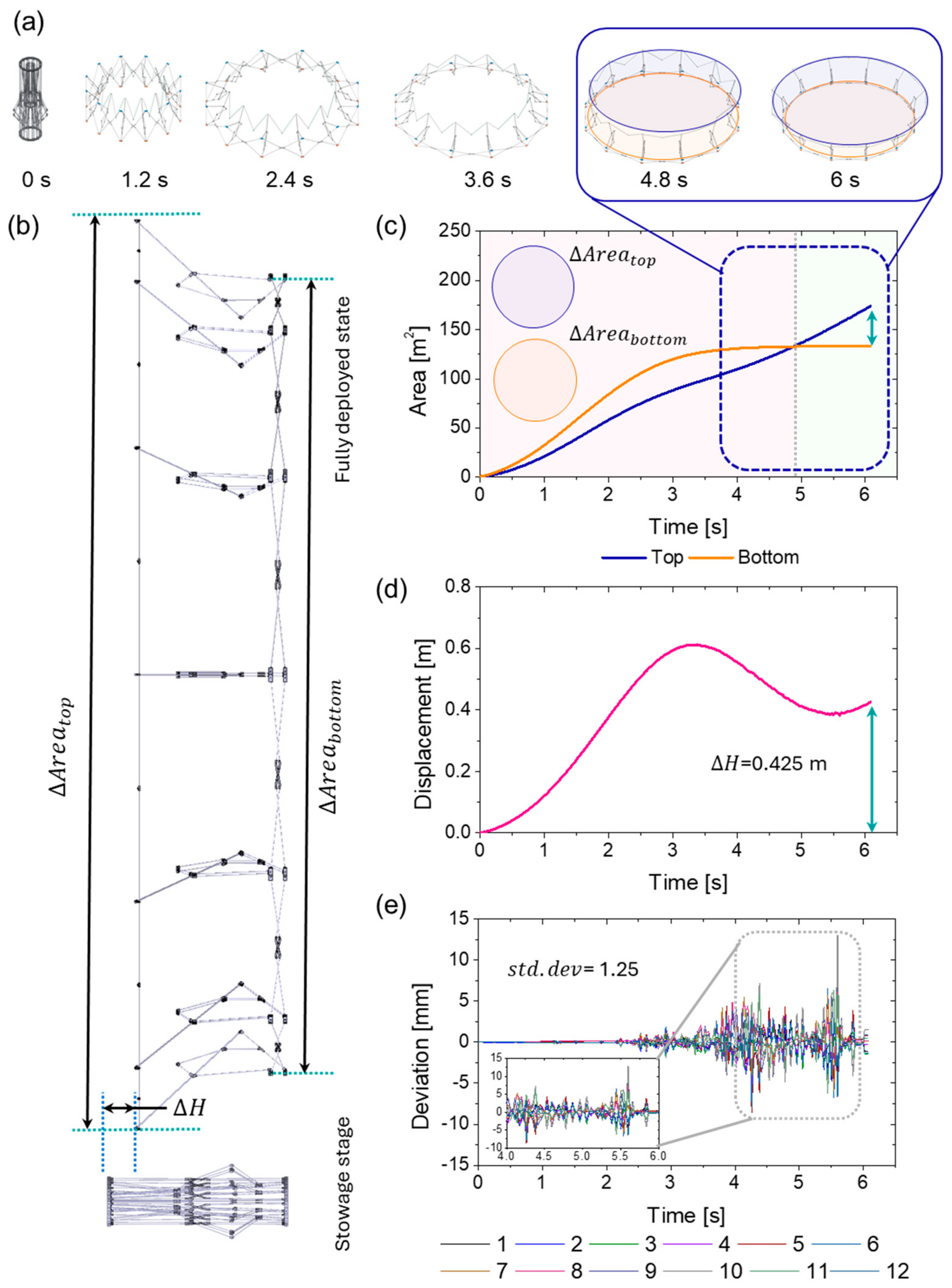
2.3. Performance Metrics of the Deployable Antenna Mechanism

Given satellites to launch, it is worth noting that space structures are required to minimize their volume and weight (density) to reduce their launching cost while maximizing the efficiency of the limited payload of the launching vehicle. In addition to these, considering that the primary objective of most of deployable antenna mechanisms is to enlarge the aperture diameter upon deployment, this work addresses two evaluators: (1) height to radius ratio, which is denoted as HR (h/π·R2 [m/m, dimensionless]), and (2) area to mass ratio, which is denoted as AM (π·r2/m [m2/kg]). These key performance metrics are related to variation in height and area with respect to variation in radius and mass, respectively. The height and radius upon the stowed state are represented as h and r, while the height and radius upon the deployed state are denoted as H and R. The total weight of the deployment mechanism is represented by ‘m’, including the frame, joints, and all other components.

3. Results and Discussion

3.1. Dynamic Analysis of the Deployable Antenna Mechanism

To better understand the dynamic characteristics and feasibility of the deployable antenna mechanism, a simulation study was performed using Recurdyn (Recurdyn 2024, FunctionBay, Republic of Korea) software. Figure 3 shows the dynamic characteristics of the deployable antenna mechanism. We assumed that one of 12 bays is fixed to the boom mechanism at the satellite, with the bottom net fixed joint of the first bay set under fixed conditions. As the driving joint of the 6-bar mechanism moves linearly along the z-axis, the upper and bottom net fixed joints move, resulting in the enlargement of the areas at the top ( Δ A r e a t o p ) and bottom ( Δ A r e a b o t t m ), as denoted in Figure 3b. Note that, due the presence of the 6-bar linkage mechanism, differences between the area at the top and the bottom occur, resulting in a conical frustum morphology with a unique tapered angle. Indeed, the 12 bays, created by the 6-bar mechanism and single pantograph mechanism, exhibit the desired kinematic trajectories (See Figure 3a and Supplementary Video S1). Specifically, as plotted in Figure 3c, the area at the top continuously increases up to 173 m2 for the given deployment time (6 s), yet the area at the bottom increases until 4.8 s, up to 133 m2, and then does not vary till 6 s. In light of these findings, the difference between the two areas at the top and bottom is 40 m2, resulting in a tapered angle of 68°. By tracking the position of the upper net fixed part, we observed that the mechanism expands from an initial stowed configuration with a diameter of 466 mm to a maximum deployed diameter of 7430 mm, depending on the movement of the driving joint.
Figure 3d shows the displacement analysis of the upper net fixed part with respect to each bay that constitutes the entire deployment mechanism. The result indicates that the upper and bottom net fixed joints of each bay exhibit identical displacements, which corresponds to the variation in height of the entire structure. Specifically, the displacement increases up to 0.6 m from 0 to 3.3 s and decreases to 0.4 m at the fully deployed state (6 s). In addition to this result, Figure 3c shows the deviation of the displacement that each bay exhibits, confirming that each unit is synchronized and operates with a single degree of freedom, as controlled by the single pantograph mechanism (standard deviation of 1.25).

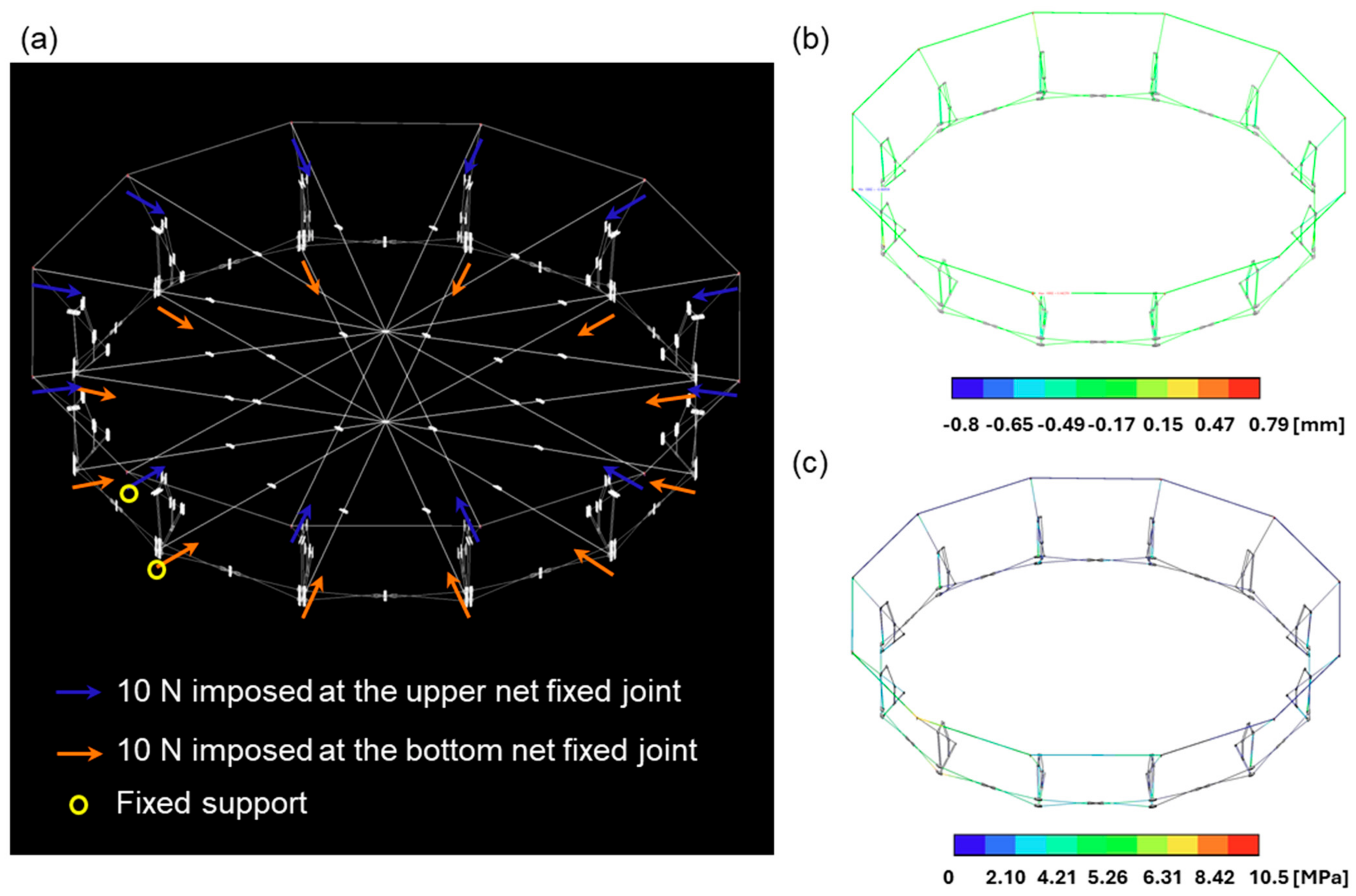
3.2. Static Analysis of the Deployable Antenna Mechanism

The mesh antenna is integrated with the net fixed part of the deployable antenna mechanism. To ensure the antenna exhibits the desired mechanical behaviors, the flatness of the mechanism must remain consistent. To validate the robustness of the proposed mechanism, the structural deformation is analyzed by applying the external loads generated by the tension from the mesh antenna. This analysis aims to identify how the mechanism can maintain its flatness under the given conditions, (e.g., under the influence of the tension forces), ensuring that the antenna can achieve its desired performance. Specifically, in a 6 m class double pantograph, the average tension in the nylon cable is 10 N, resulting in a reaction force of approximately 10.4 N acting on each bay of the upper and lower sections of the double pantograph [21]. Similarly, a tension of 10 N was applied to each point of the conical frustum-shaped deployable antenna mechanism. Moreover, similar to the given conditions imposed in the dynamic analysis, the simulation was performed under the assumption that one of 12 bays is fixed to the boom mechanism at the satellite.
With these in mind, we assumed that the linkages of the deployable antenna mechanism were made of T-300 CFRP and that the joints were made of aluminum (AL6061). The material properties used in this simulation study are detailed in Table 1. This setup allows for an accurate analysis of how the mechanism responds to the tension from the mesh antenna, ensuring that it maintains the required structural integrity and performance.
As a result of the static analysis, it is identified that the entire structure weight is 8.6 kg and that the stress distribution induced by the tension results in a maximum stress of 10.5 MPa, as depicted in Figure 4a. Specifically, in terms of deformation, each frame in the structure undergoes deformations along both the x- and y-axes, respectively. The maximum displacement in the x-axis direction is 0.8 mm, occurring at the upper part of the 6-bar linkage. The maximum displacement in the y-axis direction is 5.8 mm, observed at the V-folding bar. These results imply that the structure is likely to withstand the applied load of 10 N while maintaining its performance.
Consequently, we can tentatively conclude, by comparing the static analysis results with dynamic analysis results, that the deployable antenna mechanism can exhibit a high area-to-mass ratio of 5.003 m2/kg without significant deformations. Notably, the areas of maximum stress likely occur at the linkages and joints, yet the structure can achieve a high safety factor of 323.8 (safety factor = tensile stress/maximum stress), ensuring its structural integrity under operational conditions.

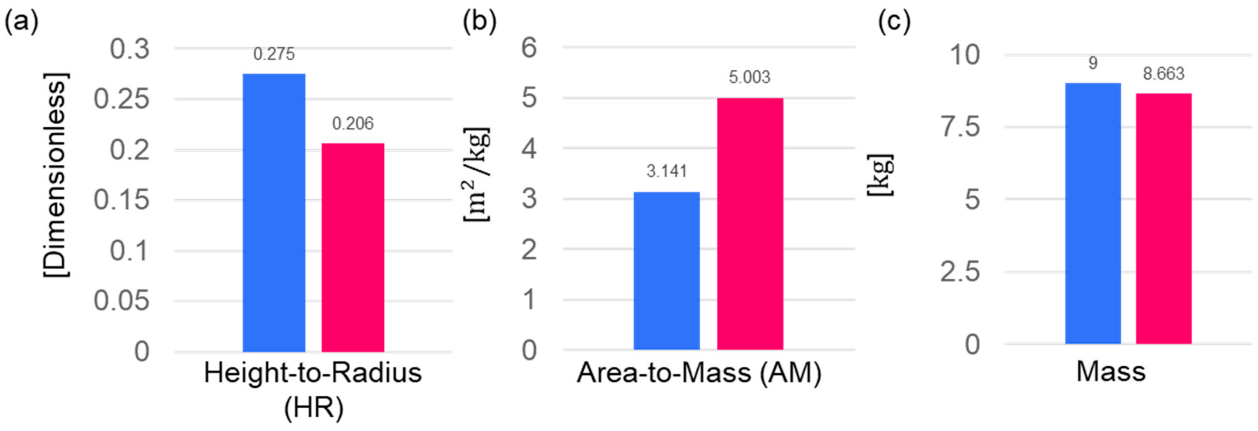
3.3. Comparatative Analysis; Double Pentograph Mechanism Versus Proposed Mechanism

Figure A2 shows the overall structures of the double pantograph (DP) mechanism [21] and of the presented deployable antenna mechanism, respectively. Herein, both mechanisms have the same height of 1650 mm. The lower ring (bottom part) of the proposed mechanism has the same diameter as the DP mechanism, yet it is noted that the upper section can achieve a diameter approximately 1.4 times larger (DP = 6 m, proposed mechanism = 7.43 m). Notably, from the area-to-mass ratio point of view, the proposed mechanism can exhibit superior mechanical properties, providing greater efficiency and performance compared to the DP mechanism.
Conclusively, Figure 5 summarizes the quantitative metrics for both the DP and proposed mechanisms. In terms of the height-to-radius ratio (HR), the proposed mechanism demonstrates a larger aperture diameter with the same height compared to the DP. Moreover, it enables a lightweight structure, with the area-to-mass ratio (AM) being approximately 1.7 times higher than that of the DP. Considering the total mass of the structure, the proposed mechanism is 0.4 kg lighter than the DP, representing a 3.74% reduction.

4. Conclusions and Future Work

This work presents the conceptual design of large-scale deployable antenna mechanism with a conical frustum shape. The proposed mechanism consists of three planar drive mechanisms: a 6-bar linkage, a single pantograph, and a V-folding mechanism, which represents a single bay. The 6-bar linkage demonstrates that the mechanical functionality can be served as actuators, exhibiting unidirectional motion. In this view, it is worth noting that our deployable mechanism has the potential to ensure a lightweight structure. In particular, the deployable antenna exhibits the desired kinematic trajectories due to the single pantograph mechanism, which couples the other two mechanisms (i.e., 6-bar linkage and V-folding mechanisms). Therefore, given that the presence of the single pantograph mechanism can reduce the redundancy of movement constraints through gears or rails, which are commonly used to enhance deployment accuracy, the lightweight structure can be achieved. The V-folding mechanism exhibits kinematic trajectories in response to the motion of specific links in the 6-bar linkage used as the longeron. Additionally, a shock-corded pole mechanism is employed to the V-folding mechanism, minimizing the number of joints.
The presented deployable antenna mechanism is hierarchically composed of 12 bays, which shows mechanical behaviors similar to the conventional double pantograph mechanism. Among the mechanisms, the kinematic characteristics of the 6-bar linkage ultimately determine the variation in areas at the top and bottom, resulting a conical frustum morphology. As a result of this simulation study, it is identified that better mechanical performance, in terms of mass and structural stability, can be achieved, compared to conventional double pantograph mechanisms. Conclusively, it is noted that the presented mechanism achieved both a lightweight design and stiffness through the kinematic constraints of the 6 bar linkage. We envision that the design principles introduced in this work can be further extended to large-scale deployable antenna structures. In this view, future work remains focused on the development of deployable antenna structures, including materials and fabrications, and experimental validation upon space environments.

Supplementary Materials

The following supporting information can be downloaded at: https://www.mdpi.com/article/10.3390/aerospace11110938/s1, Video S1: Proof-of-concept of deployable antenna mechanism incorporating six bar, single pantograph, and v-folding mechanisms.

Author Contributions

Conceptualization, H.K., B.H., S.K., H.L., K.K. and B.K.; methodology, H.K., B.H., S.K., S.J. and B.K.; software, H.K., S.K. and S.J.; validation, H.K., B.H. and S.J.; investigation, H.K., B.H., S.K. and S.J.; data curation, H.K., B.H., S.K. and S.J.; writing—original draft preparation, H.K., B.H., S.K. and S.J.; writing—review and editing, S.J. and B.K.; visualization, H.K., S.K. and S.J.; supervision, S.J. and B.K.; project administration, B.K.; funding acquisition, S.J. and B.K. All authors have read and agreed to the published version of the manuscript.

Funding

This work was supported by a grant-in-aid of HANWHA SYSTEMS, and by the Korea Research Institute for defense Technology planning and advancement and the Defense Acquisition Program Administration in 2021 (20-207-B00-011-001).

Data Availability Statement

The data presented in this study are available on request from the corresponding authors (S.J. and B.K.).

Conflicts of Interest

Author Kyungrae Koo was employed by Hanwha Systems Ltd. The remaining authors declare that the research was conducted in the absence of any commercial or financial relationships that could be construed as a potential conflict of interest.

Appendix A

Figure A1. Mechanical components of the V-folding mechanism. Isometric views of the upper net fixed joint (composed of longeron, upper bar bracket, V-folding string, and V-folding bar) at (a) the stowage stage and (b) the fully deployed state, respectively. (c) Locking mechanism to engage the V-folding mechanism at (c) the stowage stage and (d) the fully deployed state, respectively.
Aerospace 11 00938 g0a1
Figure A2. Comparative analysis of (a) the double pantograph mechanism versus (b) the presented deployable antenna mechanism having the same length of 1650 mm.
Aerospace 11 00938 g0a2

References

  1. Gao, S.; Clark, K.; Unwin, M.; Zackrisson, J.; Shiroma, W.; Akagi, J.; Maynard, K.; Garner, P.; Boccia, L.; Amendola, G. Antennas for modern small satellites. IEEE Antennas Propag. Mag. 2009, 51, 40–56. [Google Scholar] [CrossRef]
  2. Bayer, H.; Krauss, A.; Zaiczek, T.; Stephan, R.; Enge-Rosenblatt, O.; Hein, M.A. Ka-band user terminal antennas for satellite communications [antenna applications corner]. IEEE Antennas Propag. Mag. 2016, 58, 76–88. [Google Scholar] [CrossRef]
  3. Rahmat-Samii, Y.; Densmore, A.C. Technology trends and challenges of antennas for satellite communication systems. IEEE Trans. Antennas Propag. 2014, 63, 1191–1204. [Google Scholar] [CrossRef]
  4. Fu, W.; Ma, J.; Chen, P.; Chen, F. Remote sensing satellites for digital earth. In Manual of Digital Earth; Springer: Cham, Switzerland, 2020; pp. 55–123. [Google Scholar]
  5. Rovera, A.; Tancau, A.; Boetti, N.; Dalla Vedova, M.D.; Maggiore, P.; Janner, D. Fiber optic sensors for harsh and high radiation environments in aerospace applications. Sensors 2023, 23, 2512. [Google Scholar] [CrossRef] [PubMed]
  6. Raj, A.A.B.; Krishnan, P.; Darusalam, U.; Kaddoum, G.; Ghassemlooy, Z.; Abadi, M.M.; Majumdar, A.K.; Ijaz, M. A review–unguided optical communications: Developments, technology evolution, and challenges. Electronics 2023, 12, 1922. [Google Scholar] [CrossRef]
  7. Hansen, R.C. Fundamental limitations in antennas. Proc. IEEE 1981, 69, 170–182. [Google Scholar] [CrossRef]
  8. Lian, P.; Wang, C.; Xue, S.; Xu, Q.; Wang, N.; Xiang, B.; Shi, Y.; Jia, Y. Panel adjustment and error analysis for a large active main reflector antenna by using the panel adjustment matrix. IEEE Trans. Antennas Propag. 2021, 69, 6351–6363. [Google Scholar] [CrossRef]
  9. Munson, J.E. The impact of launch vehicle constraints on space system design. In Proceedings of the Massachusetts Institute of Technology, Cambridge, MA, USA, 18 November 2013. [Google Scholar]
  10. Nanjangud, A.; Underwood, C.; Rai, C.M.; Eckersley, S.; Sweeting, M.; Bianco, P. Towards robotic on-orbit assembly of large space telescopes: Mission architectures, concepts, and analyses. Acta Astronaut. 2024, 224, 379–396. [Google Scholar] [CrossRef]
  11. Kim, H.-G.; Kim, D.-G.; Do, R.-H.; Koo, K.-R.; Yu, Y.-J. Development of Deployable Reflector Antenna for the SAR-Satellite: Part 1. Design and Analysis of the Main Reflector Using Honeycomb Sandwich Composite Structure. Appl. Sci. 2024, 14, 1590. [Google Scholar] [CrossRef]
  12. Wang, B.; Zhu, J.; Zhong, S.; Liang, W.; Guan, C. Space deployable mechanics: A review of structures and smart driving. Mater. Des. 2023, 237, 112557. [Google Scholar] [CrossRef]
  13. Thomson, M.W. The AstroMesh deployable reflector. In Proceedings of the IEEE Antennas and Propagation Society International Symposium. 1999 Digest. Held in Conjunction with: USNC/URSI National Radio Science Meeting (Cat. No. 99CH37010), Orlando, FL, USA, 11–16 July 1999; pp. 1516–1519. [Google Scholar]
  14. Thomson, M. Astromesh deployable reflectors for ku and ka band commercial satellites. In Proceedings of the 20th AIAA International Communication Satellite Systems Conference and Exhibit, Montreal, QC, Canada, 12–15 May 2002; p. 2032. [Google Scholar]
  15. Chodimella, S.; Moore, J.; Otto, J.; Fang, H. Design evaluation of a large aperture deployable antenna. In Proceedings of the 47th AIAA/ASME/ASCE/AHS/ASC Structures, Structural Dynamics, and Materials Conference 14th AIAA/ASME/AHS Adaptive Structures Conference 7t, Newport, RI, USA, 1–4 May 2006; p. 1603. [Google Scholar]
  16. Peng, Y.; Zhao, Z.; Zhou, M.; He, J.; Yang, J.; Xiao, Y. Flexible multibody model and the dynamics of the deployment of mesh antennas. J. Guid. Control. Dyn. 2017, 40, 1499–1510. [Google Scholar] [CrossRef]
  17. Hutchinson, R.G.; Fleck, N.A. The structural performance of the periodic truss. J. Mech. Phys. Solids 2006, 54, 756–782. [Google Scholar] [CrossRef]
  18. Kočvara, M. On the modelling and solving of the truss design problem with global stability constraints. Struct. Multidiscip. Optim. 2002, 23, 189–203. [Google Scholar] [CrossRef]
  19. Fu, K.; Zhao, Z.; Ren, G.; Xiao, Y.; Feng, T.; Yang, J.; Gasbarri, P. From multiscale modeling to design of synchronization mechanisms in mesh antennas. Acta Astronaut. 2019, 159, 156–165. [Google Scholar] [CrossRef]
  20. Thomas, G.R.; Fadick, C.M.; Fram, B.J. Launch vehicle payload adapter design with vibration isolation features. In Proceedings of the Smart Structures and Materials 2005: Damping and Isolation, San Diego, CA, USA, 7–10 March 2005; SPIE Press: Bellingham, WA, USA, 2005; pp. 35–45. [Google Scholar]
  21. Datashvili, L.; Endler, S.; Wei, B.; Baier, H.; Langer, H.; Friemel, M.; Tsignadze, N.; Santiago-Prowald, J. Study of mechanical architectures of large deployable space antenna apertures: From design to tests. CEAS Space J. 2013, 5, 169–184. [Google Scholar] [CrossRef]
Figure 1. A conceptual design of the deployable antenna mechanism. (a) Sequential images showing the deployable antenna at different stages (from stowed (left) to fully deployed stage (right)). A hierarchical composition composed of (b) a 6-bar linkage mechanism, (c) a single pantograph mechanism, and (d) a V-folding mechanism (scale bar = 1 m).
Aerospace 11 00938 g001
Figure 2. Working principle of the primary mechanisms. (a) Once the driving joint moves along vertical direction, the upper net fixed joints of the 6-bar linkage mechanism exhibit a particular kinematic trajectory. (b) As the driving joint moves vertically, the connecting joint of the single pantograph mechanism exhibits arc-trajectories, shown in blue. (c) The V-folding mechanism is coupled with 6-bar linkage and single pantograph mechanisms, and the V-folding joints move along a particular trajectory, shown in green. (Note that the pink-colored dashed lines indicate the movement of the driving joint along vertical direction, and the solid lines indicate kinematic trajectories of each mechanism).
Aerospace 11 00938 g002
Figure 3. Dynamic simulation results. (a) Sequential results of the deployable antenna mechanisms, with steps of 1.2 s. (b) A schematic of the deployable antenna mechanism, showing the variation in height ( Δ H ) and the variation in areas at the top and bottom ( Δ A r e a t o p ,   Δ A r e a b o t t o m ), respectively. (c,d) Responses of the area and displacement (variation in height between the upper and bottom net fixed joints) with respect to the deployment time. (e) Deviations in the displacement variation of each node, indicating the distance between the upper and bottom net fixed joints.
Aerospace 11 00938 g003
Figure 4. Static analysis results. (a) Simulation setup. The blue- and orange-colored arrows indicate a force imposed at the upper and bottom net fixed joint, respectively, and the yellow-colored circles refer to the fixed supports. (b,c) Responses of the deformation and the VonMises stress with respect to the imposed load of 10 N.
Aerospace 11 00938 g004
Figure 5. Comparative analysis—Double pantograph (blue color bar) versus presented mechanism (pink color bar). The bar graphs show mechanical performances in terms of (a) height-to-radius ratio, (b) area-to-mass ratio, and (c) mass, respectively.
Aerospace 11 00938 g005
Table 1. Material properties employed at static simulation setup.
MaterialsDensity [g/cm3]Elastic Modulus [GPa]Poisson’s RatioShear Strength [MPa]Tensile Strength [MPa]
CFRP T-3001.62400.25403400
AL60612.768.90.33207276
Disclaimer/Publisher’s Note: The statements, opinions and data contained in all publications are solely those of the individual author(s) and contributor(s) and not of MDPI and/or the editor(s). MDPI and/or the editor(s) disclaim responsibility for any injury to people or property resulting from any ideas, methods, instructions or products referred to in the content.

