
Topology Optimization of the Bracket Structure in the Acquisition, Pointing, and Tracking System Considering Displacement and Key Point Stress Constraints


Abstract
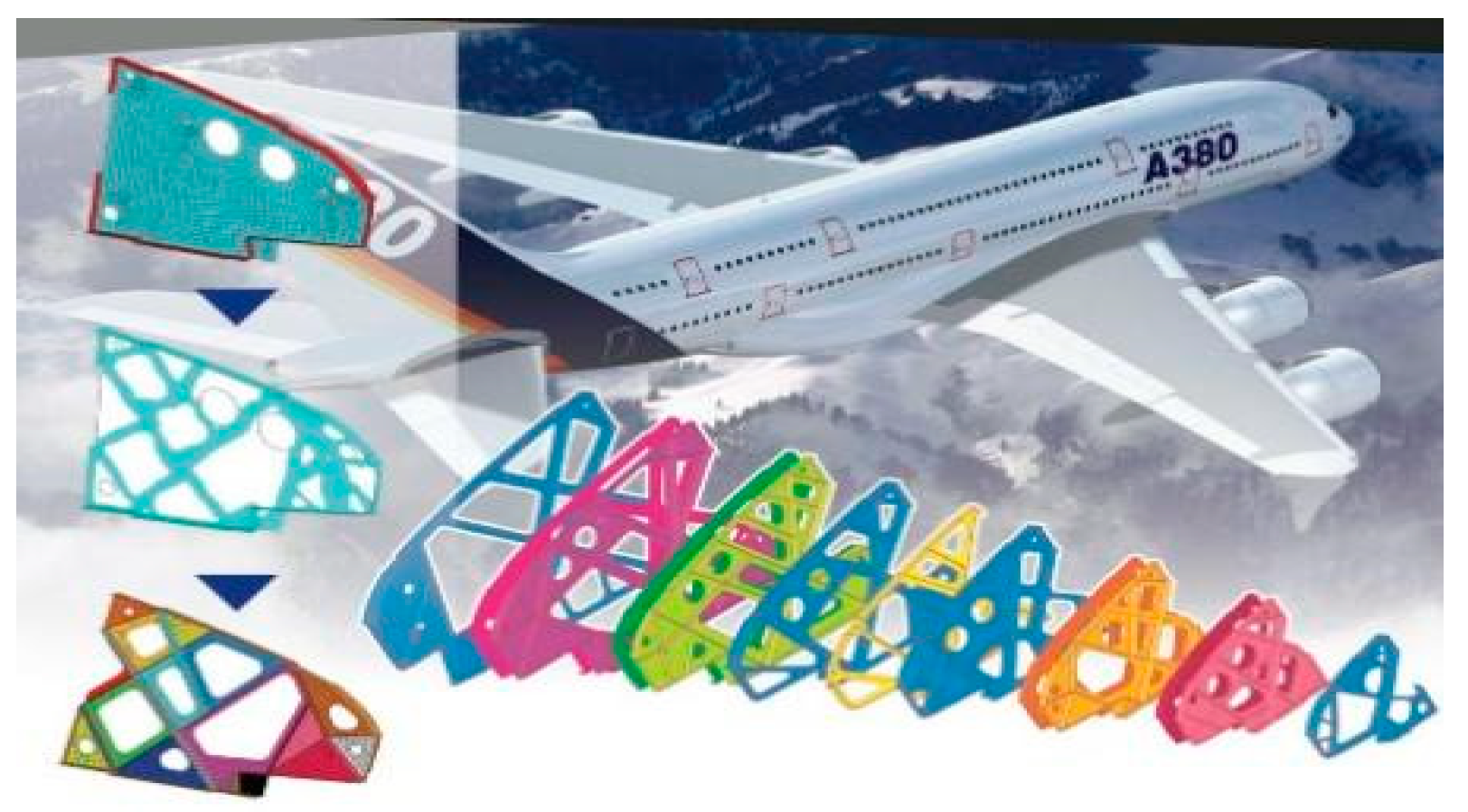
1. Introduction
2. Material Interpolation Format and Mathematical Model for Structural Topology Optimization of the APTS Mechanical Support Structure Bracket
2.1. Material Interpolation Format of SIMP and Structural Analysis
2.2. Mathematical Model for Structural Topology Optimization of the APTS Mechanical Support Structure Bracket
3. Explicit Sensitivity Analysis of Objective Functions and Constraints
3.1. Sensitivity of Compliance to Design Variables
3.2. Sensitivity of Displacement Constraints with Respect to Design Variables
3.3. Sensitivity of Stress Constraints with Respect to Design Variables
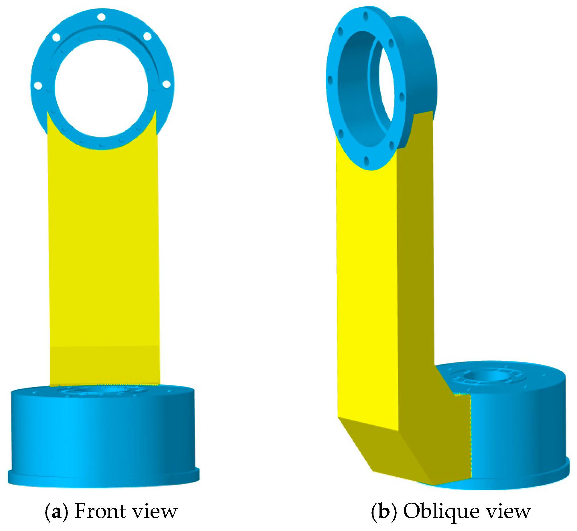
4. Structural Analysis of the APTS’ L-Shaped Bracket Structure
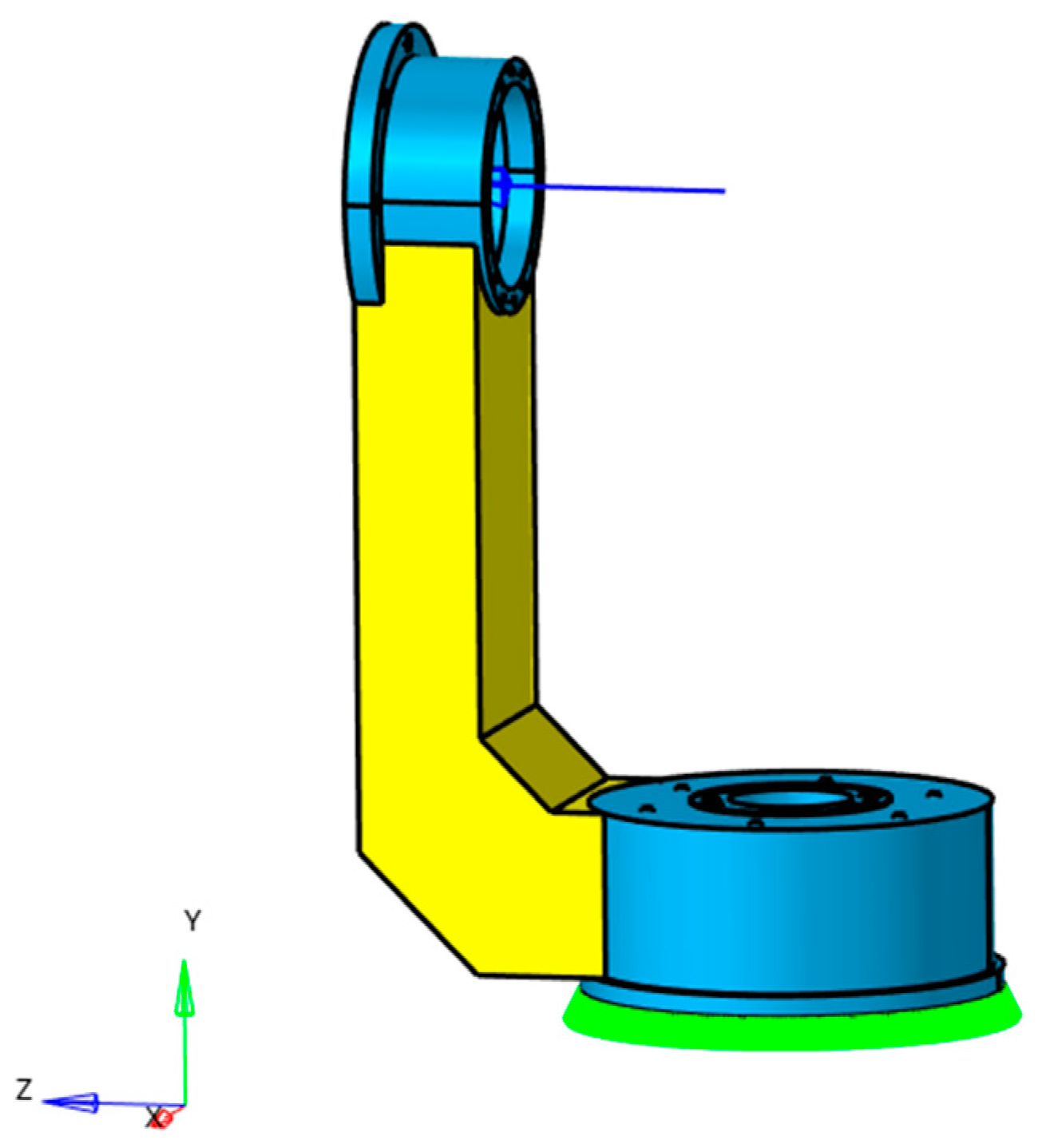
4.1. Loading and Boundary Conditions of the APTS’s Bracket Structure
4.2. Material Properties and Mesh Division of the APTS’s Bracket Structure
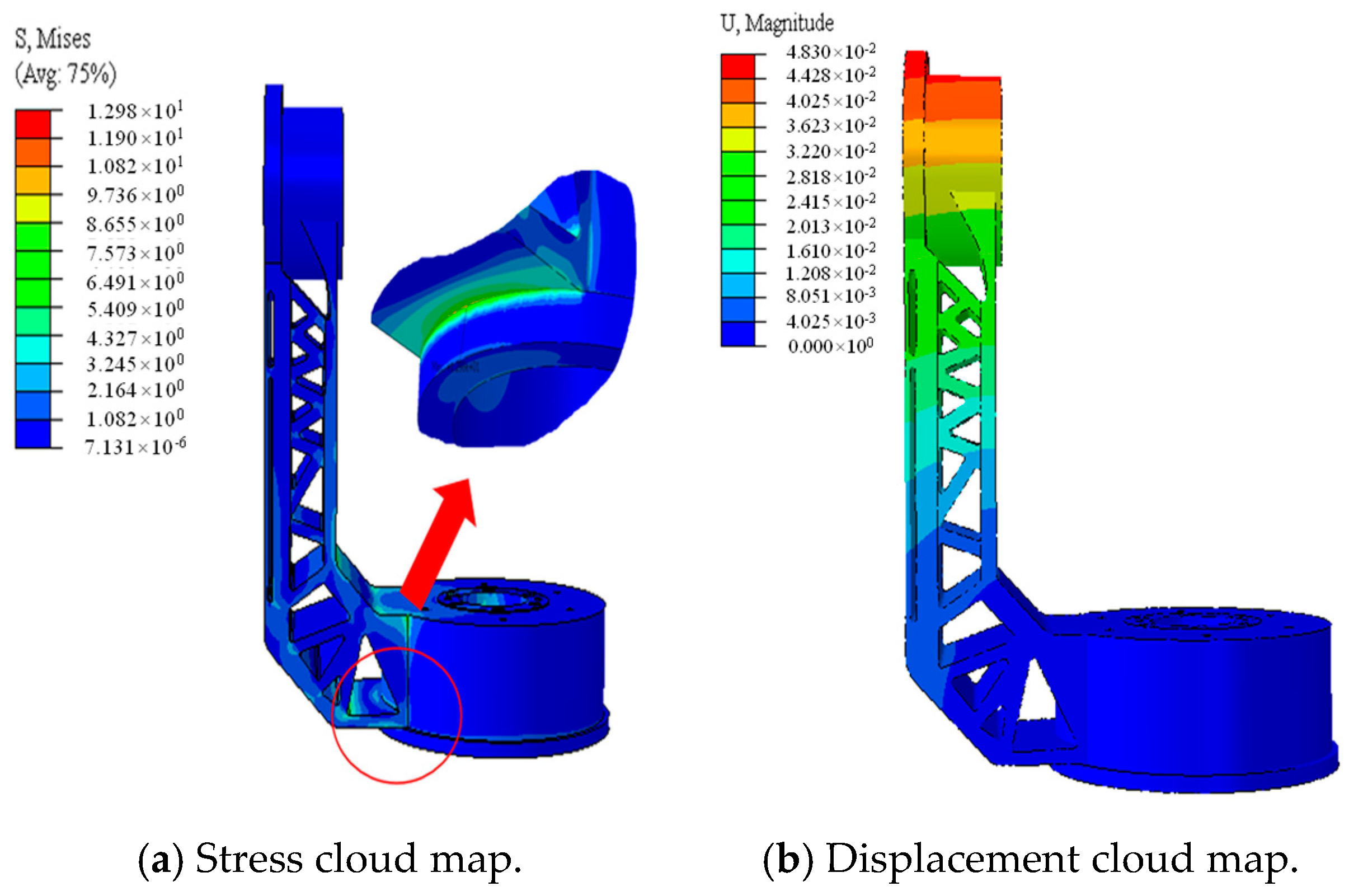
4.3. Static Analysis of the APTS’s Bracket Structure
5. Topology Design Optimization of the APTS’s Bracket Structure
5.1. Preprocessing for the Geometric Model of the Support Structure
5.2. Boundary Conditions and Loading Application for the Support Structure
5.3. Manufacturing Constraints for the Topology Optimization of the Support Structure
6. Numerical Examples and Discussion of Results
6.1. Topology Optimization Results Considering Displacement and Stress Constraints
6.2. Topology Optimization Results for Minimizing Compliance Considering Volume Fraction Constraints
6.3. Topology Optimization Structure Smoothing for the Support Structure
6.4. Verification of the Strength and Stiffness of the Optimized Structure
7. Conclusions
Author Contributions
Funding
Data Availability Statement
Conflicts of Interest
References
- Bendsøe, M.P. Topology design of structures, materials and mechanisms—Status and perspectives. In IFIP Conference on System Modeling and Optimization; Springer: Boston, MA, USA, 1999; pp. 1–17. [Google Scholar]
- Zhu, J.; Zhang, W.; Beckers, P.; Chen, Y.; Guo, Z. Simultaneous design of components layout and supporting structures using coupled shape and topology optimization technique. Struct. Multidiscip. Optim. 2008, 36, 29–41. [Google Scholar] [CrossRef]
- Duan, Z.Y.; Liu, Y.Q.; Fan, J.L.; Long, K.; Xu, B.; Zhu, J.H.; Yan, J. Concurrent multi-material and multi-scale design optimization of fiber-reinforced composite material and structures for minimum structural compliance. Compos. Struct. 2023, 311, 116796. [Google Scholar] [CrossRef]
- Ho, T.H.; Milner, S.D.; Davis, C.C. Pointing, acquisition, and tracking system with omnivision. Free Space Laser Commun. V SPIE 2005, 5892, 420–431. [Google Scholar]
- Kaushal, H.; Jain, V.K.; Kar, S.; Kaushal, H.; Jain, V.K.; Kar, S. Acquisition, tracking, and pointing. In Free Space Optical Communication; Springer: New Delhi, India, 2017; pp. 119–137. [Google Scholar]
- Cheng, K.T.; Olhoff, N. An investigation concerning optimal design of solid elastic plates. Int. J. Solids Struct. 1981, 17, 305–323. [Google Scholar] [CrossRef]
- Bendsøe, M.P.; Kikuchi, N. Generating optimal topologies in structural design using a homogenization method. Comput. Methods Appl. Mech. Eng. 1988, 71, 197–224. [Google Scholar] [CrossRef]
- Xie, Y.M.; Steven, G.P. Optimal design of multiple load case structures using an evolutionaryprocedure. Eng. Comput. 1994, 11, 295–302. [Google Scholar] [CrossRef]
- Allaire, G.; Jouve, F.; Toader, A.M. Structural optimization using sensitivity analysis and a level-set method. J. Comput. Phys. 2004, 194, 363–393. [Google Scholar] [CrossRef]
- Díaaz, A.R.; Kikuchi, N. Solutions to shape and topology eigenvalue optimization problems using a homogenization method. Int. J. Numer. Methods Eng. 1992, 35, 1487–1502. [Google Scholar] [CrossRef]
- Suzuki, K.; Kikuchi, N. A homogenization method for shape and topology optimization. Comput. Methods Appl. Mech. Eng. 1991, 93, 291–318. [Google Scholar] [CrossRef]
- Zhang, W.; Li, D.; Zhang, J.; Guo, X. Minimum length scale control in structural topology optimization based on the Moving Morphable Components (MMC) approach. Comput. Methods Appl. Mech. Eng. 2016, 311, 327–355. [Google Scholar] [CrossRef]
- Rozvany, G. The SIMP method in topology optimization-theoretical background, advantages and new applications. In Proceedings of the 8th Symposium on Multidisciplinary Analysis and Optimization, Long Beach, CA, USA, 6–8 September 2000. [Google Scholar]
- Zuo, W.; Saitou, K. Multi-material topology optimization using ordered SIMP interpolation. Struct. Multidiscip. Optim. 2017, 55, 477–491. [Google Scholar] [CrossRef]
- Norato, J.; Haber, R.; Tortorelli, D.; Bendsøe, M.P. A geometry projection method for shape optimization. Int. J. Numer. Methods Eng. 2004, 60, 2289–2312. [Google Scholar] [CrossRef]
- Guo, X.; Zhang, W.; Zhang, J.; Yuan, J. Explicit structural topology optimization based on moving morphable components (MMC) with curved skeletons. Comput. Methods Appl. Mech. Eng. 2016, 310, 711–748. [Google Scholar] [CrossRef]
- Hoang, V.N.; Jang, G.W. Topology optimization using moving morphable bars for versatile thickness control. Comput. Methods Appl. Mech. Eng. 2017, 317, 153–173. [Google Scholar] [CrossRef]
- Coniglio, S.; Morlier, J.; Gogu, C.; Amargier, R. Generalized geometry projection: A unified approach for geometric feature based topology optimization. Arch. Comput. Methods Eng. 2020, 27, 1573–1610. [Google Scholar] [CrossRef]
- París, J.; Martínez, S.; Navarrina, F.; Colominas, I.; Casteleiro, M. Topology optimization of aeronautical structures with stress constraints: General methodology and applications. Proc. Inst. Mech. Eng. Part G J. Aerosp. Eng. 2012, 226, 589–600. [Google Scholar] [CrossRef]
- López, C.; Baldomir, A.; Hernández, S. Deterministic versus reliability-based topology optimization of aeronautical structures. Struct. Multidiscip. Optim. 2016, 53, 907–921. [Google Scholar] [CrossRef]
- Berrocal, L.; Fernández, R.; González, S.; Periñán, A.; Tudela, S.; Vilanova, J.; Lasagni, F. Topology optimization and additive manufacturing for aerospace components. Prog. Addit. Manuf. 2019, 4, 83–95. [Google Scholar] [CrossRef]
- Sigmund, O. Topology optimization: A tool for the tailoring of structures and materials. Philos. Trans. R. Soc. London. Ser. A Math. Phys. Eng. Sci. 2000, 358, 211–227. [Google Scholar] [CrossRef]
- Arora, J.S.; Wang, Q. Review of formulations for structural and mechanical system optimization. Struct. Multidiscip. Optim. 2005, 30, 251–272. [Google Scholar] [CrossRef]
- Iandiorio, C.; Milani, D.; Salvini, P. Optimal Uniform Strength Design of Frame and Lattice Structures. Comput. Struct. 2024, 301, 107430. [Google Scholar] [CrossRef]
- Lian, H.; Christiansen, A.N.; Tortorelli, D.A.; Sigmund, O.; Aage, N. Combined shape and topology optimization for minimization of maximal von Mises stress. Struct. Multidiscip. Optim. 2017, 55, 1541–1557. [Google Scholar] [CrossRef]
- Asadpoure, A.; Valdevit, L. Topology optimization of lightweight periodic lattices under simultaneous compressive and shear stiffness constraints. Int. J. Solids Struct. 2015, 60, 1–16. [Google Scholar] [CrossRef]
- Zhu, J.H.; Zhou, H.; Wang, C.; Zhou, L.; Yuan, S.Q.; Zhang, W.H. A review of topology optimization for additive manufacturing: Status and challenges. Chin. J. Aeronaut. 2021, 34, 91–110. [Google Scholar] [CrossRef]
- Meng, L.; Zhang, W.; Quan, D.; Shi, G.; Tang, L.; Hou, Y.; Gao, T. From topology optimization design to additive manufacturing: Today’s success and tomorrow’s roadmap. Arch. Comput. Methods Eng. 2020, 27, 805–830. [Google Scholar] [CrossRef]
- Sigmund, O.; Maute, K. Topology optimization approaches: A comparative review. Struct. Multidiscip. Optim. 2013, 48, 1031–1055. [Google Scholar] [CrossRef]
- Eschenauer, H.A.; Olhoff, N. Topology optimization of continuum structures: A review. Appl. Mech. Rev. 2001, 54, 331–390. [Google Scholar] [CrossRef]
- Wu, J.; Sigmund, O.; Groen, J.P. Topology optimization of multi-scale structures: A review. Struct. Multidiscip. Optim. 2021, 63, 1455–1480. [Google Scholar] [CrossRef]
- Bendsøe, M.P.; Sigmund, O. Material interpolation schemes in topology optimization. Arch. Appl. Mech. 1999, 69, 635–654. [Google Scholar] [CrossRef]
- Stolpe, M.; Svanberg, K. An alternative interpolation scheme for minimum compliance topology optimization. Struct. Multidiscip. Optim. 2001, 22, 116–124. [Google Scholar] [CrossRef]


| Objective Function | Maximum Displacement/mm | Maximum von Mises Stress/MPa | Weight/kg |
|---|---|---|---|
| Minimize volume (with displacement constraints) | 0.04420 | 11.81 | 0.648 |
| Minimize volume (with displacement and stress constraints) | 0.04718 | 9.027 | 0.635 |
| Minimize compliance | 0.04830 | 12.98 | 0.655 |
Disclaimer/Publisher’s Note: The statements, opinions and data contained in all publications are solely those of the individual author(s) and contributor(s) and not of MDPI and/or the editor(s). MDPI and/or the editor(s) disclaim responsibility for any injury to people or property resulting from any ideas, methods, instructions or products referred to in the content. |
© 2024 by the authors. Licensee MDPI, Basel, Switzerland. This article is an open access article distributed under the terms and conditions of the Creative Commons Attribution (CC BY) license (https://creativecommons.org/licenses/by/4.0/).
Share and Cite
Gao, B.; Yang, H.; Chen, W.; Wang, H. Topology Optimization of the Bracket Structure in the Acquisition, Pointing, and Tracking System Considering Displacement and Key Point Stress Constraints. Aerospace 2024, 11, 939. https://doi.org/10.3390/aerospace11110939
Gao B, Yang H, Chen W, Wang H. Topology Optimization of the Bracket Structure in the Acquisition, Pointing, and Tracking System Considering Displacement and Key Point Stress Constraints. Aerospace. 2024; 11(11):939. https://doi.org/10.3390/aerospace11110939
Chicago/Turabian StyleGao, Bo, Hongtao Yang, Weining Chen, and Hao Wang. 2024. "Topology Optimization of the Bracket Structure in the Acquisition, Pointing, and Tracking System Considering Displacement and Key Point Stress Constraints" Aerospace 11, no. 11: 939. https://doi.org/10.3390/aerospace11110939
APA StyleGao, B., Yang, H., Chen, W., & Wang, H. (2024). Topology Optimization of the Bracket Structure in the Acquisition, Pointing, and Tracking System Considering Displacement and Key Point Stress Constraints. Aerospace, 11(11), 939. https://doi.org/10.3390/aerospace11110939