Abstract
Tactile maps are widely recognized as useful tools for mobility training and the rehabilitation of visually impaired individuals. However, current tactile maps lack real-time versatility and are limited because of high manufacturing and design costs. In this study, we introduce a device (i.e., ClaySight) that enhances the creation of automatic tactile map generation, as well as a model for wearable devices that use low-cost laser imaging, detection, and ranging (LiDAR,) used to improve the immediate spatial knowledge of visually impaired individuals. Our system uses LiDAR sensors to (1) produce affordable, low-latency tactile maps, (2) function as a day-to-day wayfinding aid, and (3) provide interactivity using a wearable device. The system comprises a dynamic mapping and scanning algorithm and an interactive handheld 3D-printed device that houses the hardware. Our algorithm accommodates user specifications to dynamically interact with objects in the surrounding area and create map models that can be represented with haptic feedback or alternative tactile systems. Using economical components and open-source software, the ClaySight system has significant potential to enhance independence and quality of life for the visually impaired.
1. Introduction
Tactile maps have long been recognized by professionals as useful tools in mobility training and the rehabilitation of visually impaired people [1,2]. Notably, there have been multiple studies and best-practice guidelines produced regarding tactile graphics [1,2,3,4,5,6,7]. The results of a survey on user requirements for tactile maps indicated that most users viewed them as the best way to represent spatial information, as they prefer accurate, understandable, and clutter-free maps [2]. The history of tactile maps as a commercially available technology predates 3D printing. For instance, microcapsule paper has been used to automatically create maps from computer-generated images, though the required equipment is prohibitively expensive [8]. Additionally, these maps are non-dynamic and only feature static navigational paths.
Commercially available 3D printers have enabled the automated modeling and production of a wide range of tactile surfaces and feedback systems at a reduced cost. Götzelmann and Pavkovic presented an approach to automatically map OpenStreetMap data on layered 2.1-Dimension (2.1-D) models with braille annotations, explicitly for use with 3D printers [9]. Another approach, known as Touch Mapper, uses a web interface that allows users to query addresses and download 3D map models of the surrounding area [10]. Although it is possible to generate maps that identify roadways, railways, waterways, and buildings, the maps have a limited number of size and scale options, based on existing large landmarks. Several studies have focused on creating dynamic tactile maps that update in real time with their surrounding environment [1,2,3,5]. Algorithms that can produce 3D-printable tactile maps from online repositories of geospatial data are crucial for allowing visually impaired individuals to create customized static maps, which are useful for navigation along large areas like roadways; however, such algorithms cannot perform simultaneous localization.
An earlier effort to produce customized tactile maps—Tactile Maps Automated Production (TMAP)—was initiated at the Smith-Kettlewell Eye Research Institute [8]. TMAP offered visually impaired users the ability to specify maps using an accessible web interface that would generate digital files to be printed on a braille embosser. Another project, the Tactile Maps Automated Creation System (TMACS), was later adapted to use OpenStreetMap data and generate maps of locations around the world [11]. Based on our review, there are no other services that allow visually impaired individuals to produce customized tactile maps with simultaneous localization. Feature annotation is a major challenge in the generation of tactile maps because it depends on the features used, the relative distance of the features, and dynamically positioned objects. Brock et al. explored how various gestures could be used to enhance interactive tactile maps using commercially available multi-touch screen devices combined with raised-line printing on paper [12,13]. Despite the availability of multiple generalization algorithms and models, a holistic solution has not been developed for processing an entire map at once.
Prior methods have substantial limitations. Götzelmann and Pavkovic’s approach, and similar solutions, require downloading online data and 3D printing solutions from archival online sources, limiting their practicality for real-time feedback [9,10]. TMAP and TMACS require web interfaces, which generate maps based online archival data [8,11]. These solutions are limited when navigating areas without public archival data available, such as busy streets, public gatherings, and private residences. Other solutions require pre-printed maps and potentially distracting interactions with devices [12,13]. Existing solutions are of dubious practicality in areas with poor online connections or frequent activity. A contrast is shown in Table 1. In contrast, a wearable device providing real-time feedback without an online connection would overcome issues with prior work.

Table 1.
Comparison of ClaySight with prior work.
In this work, we propose a simultaneous localization and mapping (SLAM)-based wearable device (i.e., ClaySight) that uses LiDAR sensors to improve the reliability of navigation for the visually impaired. Unlike previous approaches, our system allows for 360° scanning of surrounding objects. As long as there is a sufficient number of points being tracked through each frame, the sensor’s orientation and the structure of the surrounding physical environment can be rapidly understood. SLAM systems operate in real time, requiring processing time before merging the location and mapping data.
2. Design
Designing the ClaySight system required optimizing sensor resolution and haptic feedback. Visually impaired individuals already had access to various tools that generate static tactile maps. Dynamic systems, however, were practically non-existent. To tackle this issue, we explored other examples of dynamic mapping (e.g., sonar and radar) [2,5]. Such systems can detect changes in an object’s position relative to a source object. As with LiDAR, effective 2D mapping can be achieved in 360° [13,14], which is necessary for SLAM operation. The ability to detect the dynamic positions of objects relative to a source object is known as localization, and storing the data is known as mapping.
ClaySight can leverage these concepts because affordable distance-measuring sensors have recently become more prominent in the market. Using commercial LiDAR, with an indexed rotational system in place, the proposed system provides a complete circular map of distances up to 12 m, similar to most radar systems. As a wearable device, this system also enables the generation of 3D maps owing to the free rotation of the human body. This allows for more dynamic mapping, accounting for both the vertical and horizontal axes. When combined with a microcontroller and an algorithm to interpret sensor data, various feedback systems can be used to personalize the dynamic mapping features according to user preferences.
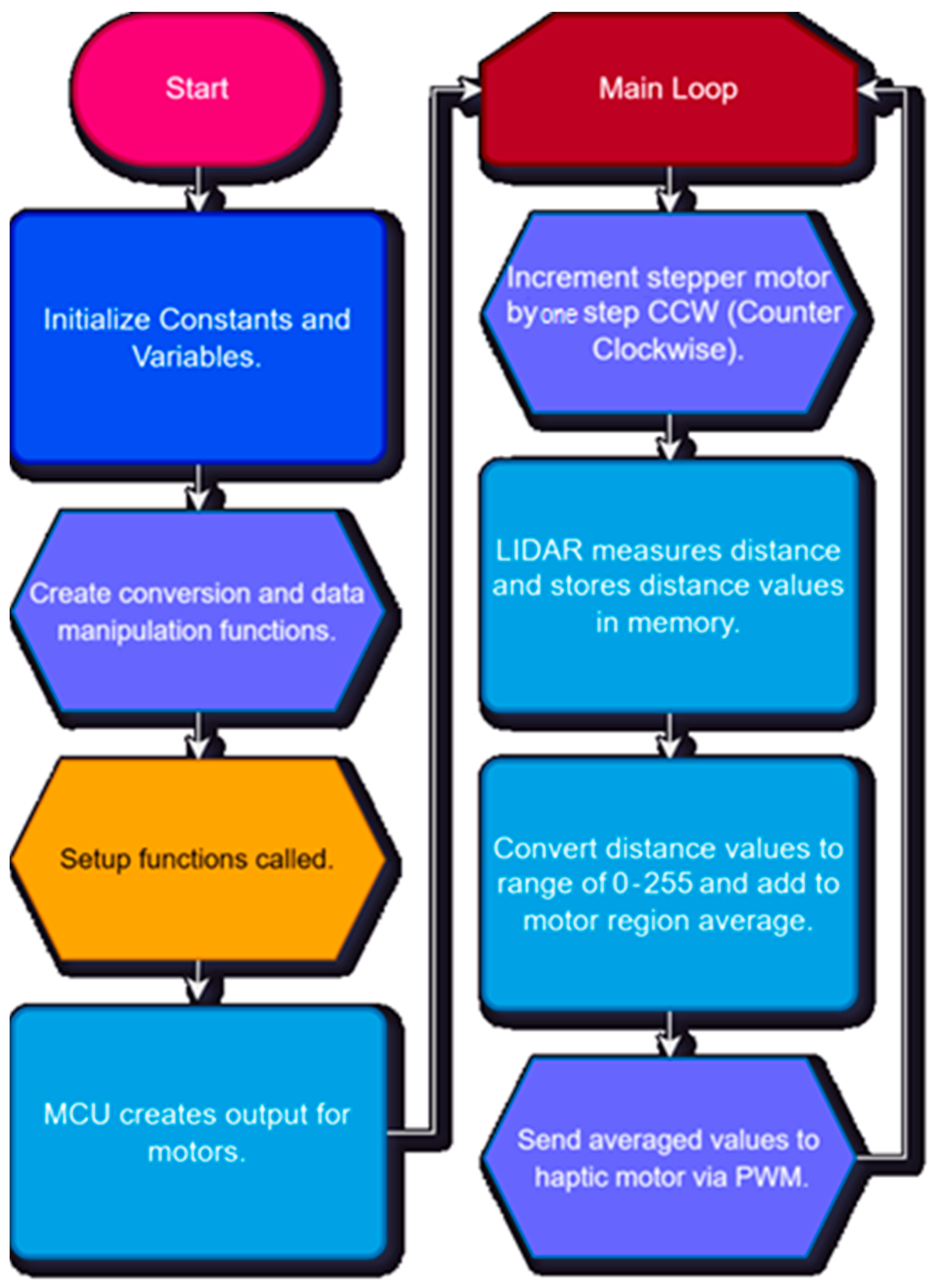
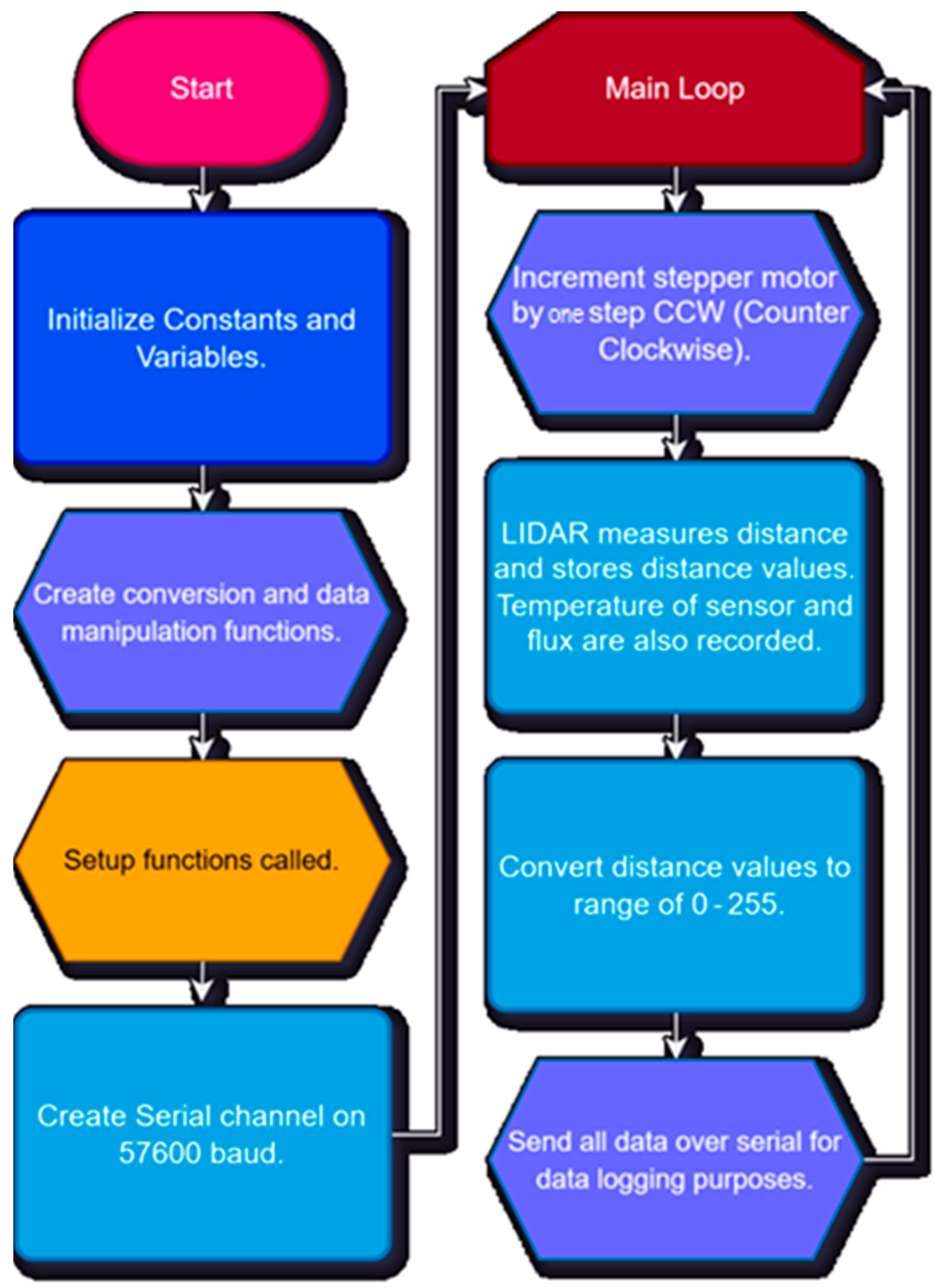
The operational framework for the device is shown in Figure 1. The microcontroller’s software does not require a specific feedback system. However, the prototypes use haptic feedback motors, and the intensity of the rotation is controlled by converting the average sectional distances to pulse-width modulation (PWM) values. This means that as an individual approaches to an object, the haptic motors vibrate with greater intensity. The closer an object is, the more intense the stepper motor vibrates in that direction. As the individual moves further away, they vibrate with decreasing intensity and then stop vibrating entirely. The device rotates a LiDAR sensor around in a continuous circle. To encode the distance, the distance value returned is divided by 12 m, and converted into an integer between 0 and 255. To reduce latency and use memory efficiently, incoming distance values are read on a general-purpose input/output (GPIO) pin on the RP2040 microcontroller (Raspberry Pi Ltd., Cambridge, UK), which outputs a control signal for each haptic motor. The RP2040 acts as the microcontroller unit (MCU). The RP2040 can support up to 16-bits of resolution, but other widely used open source MCUs only support 8-bit outputs. As integration with open-source components was important, 8 bits was sufficient for the project. Similarly, 8 bits was sufficient for low-latency adjustment of motor intensity, rather than an abrupt, intense activation pulse.
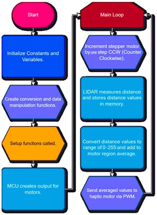
Figure 1.
Flowchart for ClaySight workflow with LiDAR scanning and generating haptic feedback.
The device uses a gear multiplier of 1:3 to accommodate the low-speed 28BYJ-48 stepper motor (Kiatronics, Tauranga, New Zealand). The gear ratio is a crucial factor in the calculations conducted by the algorithm, which is used to properly register one full rotation of the TF-Luna LiDAR sensor (Benewake, Beijing, China). The sensor can poll at 250 Hz, and the functional resolution is <12 m. The LiDAR sensor sits on a smaller gear, which is turned by the primary gear attached to the aforementioned stepper motor. A complete rotation of the device takes approximately 3.2 s. With each step, the distance measured by the LiDAR sensor is recorded and stored in the dynamic memory. These measurements and stored data enable localization and mapping in real time. Once the data are stored in the dynamic memory, they are averaged per section of a circular map, with each section being split into one of eight outputs. Each output can be encoded in up to eight separate motors, each corresponding to a different “sector” of averaged values. Averaging the distance values for each “sector” acts as a low-pass filter, removing noise.
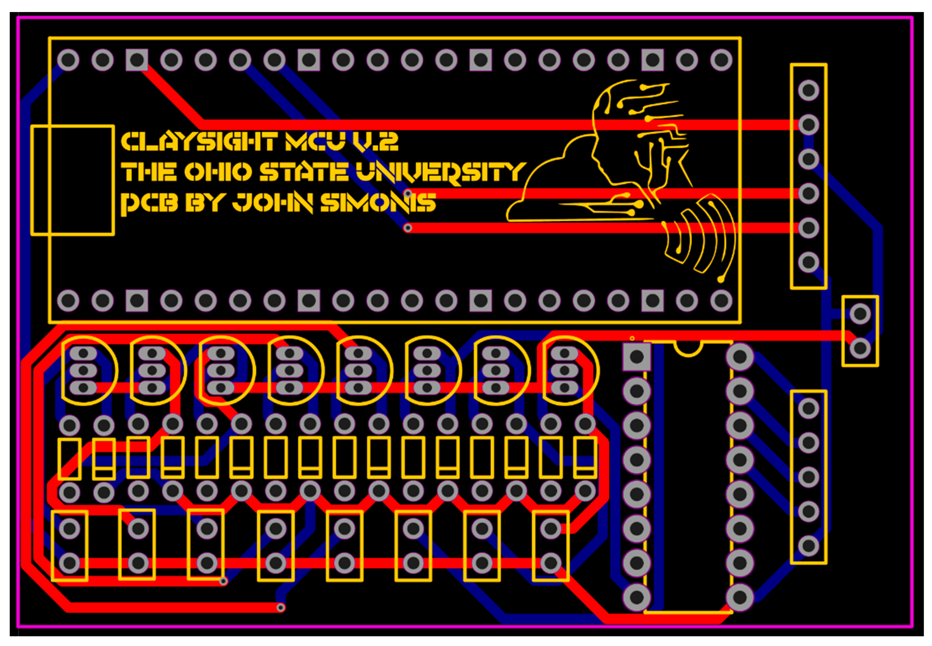
For control, a custom printed circuit board (PCB) was used, as shown in Figure 2, featuring slots for power, a microcontroller, and vibrators. Up to eight motors can be added mounted on the device, and the default setting is four motors.
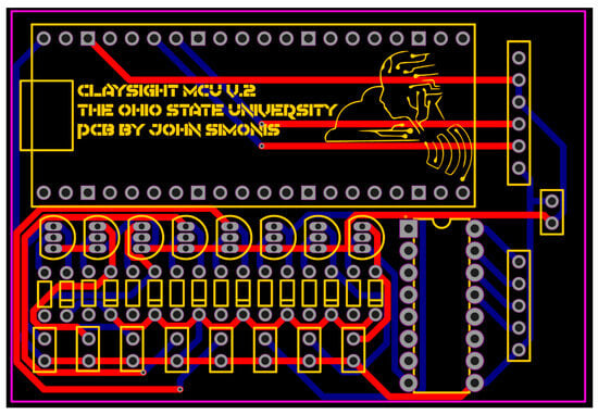
Figure 2.
PCB layout for ClaySight, including labeled component slots. The detailed schematic is provided in the Supplementary Files of the paper.
The ClaySight prototypes use two pieces of custom software. One program runs on the RP2040 microcontroller and the other exclusively runs for data logging, as previously mentioned. The program running natively on the device manages all the logic for scanning and mapping the environment around the user. The program maintains the rotation of the device’s stepper motor at a controlled speed. Over the course of its runtime, the program gradually increments the rotation of the stepper motor until a full rotation has been completed. Owing to the modular design of the software, the program is designed with multiple modifiable parameters, one of which is the revolutions-per-minute (RPM) of the 28BYJ-48 stepper motor. In its current settings, the LiDAR unit can complete a rotation in 3.2 s. The default motor settings are stable at 17.5 RPM, although it is capable of reaching 30 RPM. The motor parameters are controlled with a ULN2003 motor driver board (ST Microelectronics, Plan-les-Ouates, Switzerland).
The major configurable entities within the software include a settable maximum distance and a dead zone. Considering that the LiDAR sensor covers 360°, the user may obtain false readings from the space occupied by their own body. These settings are configurable in a simple manner to mitigate this issue. The dead zone accounts for an area close to the user, for which recorded obstacles are not mapped, set by default to 10 cm. The maximum distance controls the maximum scanning range of the device using the individual as a point of reference. The device is powered by a 3.7 V lithium polymer battery with 2850 mAh, regulated by a TP4056 integrated circuit to provide a constant 5 V. The battery life depends upon the power drawn by the active motors, which the default value of 17.5 RPM was designed to maximize. The LiDAR and microprocessor draw a constant 70 mA, and each motor draws approximately 6.25 mA. With the standard configuration of four motors, battery life is approximately 10.5 h. With eight motors, the battery life is approximately 6 h. In both settings, the voltage and current in the device are at common, safe levels comparable to most commercial electronics.
The software running on the RP2040 microcontroller also includes a special debugging mode that enables interfacing with a standard computer. Here, we deployed an additional program, the ClaySight data logger. This program communicates with the ClaySight system over a serial connection at 57,600 baud. The device is automatically detected after plugging into a standard Universal Serial Bus (USB) port. Once the program is launched, it scans for the ClaySight device by looking through all serial devices at 57,600 baud. GPIO pins are the primary method of interfacing electronic components within the device. Once the device is detected, a command is issued that starts an automatic debugging sequence. The device sends all of its data points—recorded at each step of the LiDAR sensor’s rotation—over the serial terminal connection. These data points are then recorded in a spreadsheet file named by the user. The data-logging system is illustrated in Figure 3, and it can be adapted to extract data for other purposes, such as LiDAR odometry.
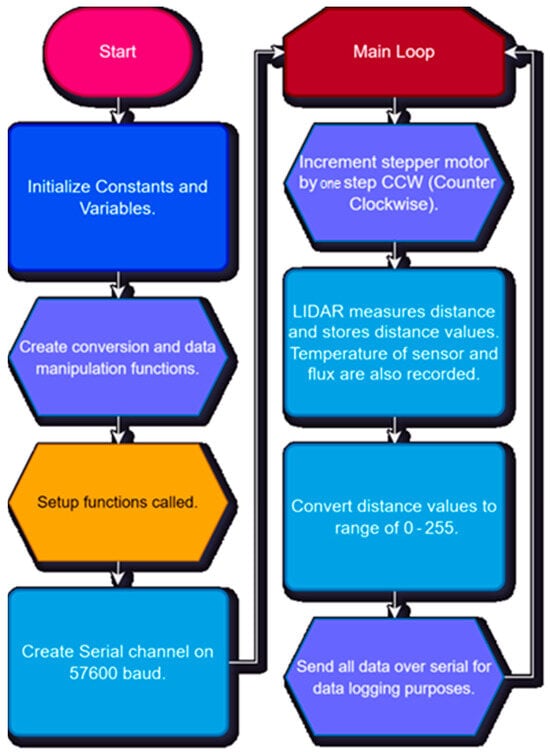
Figure 3.
Data-logging function flowchart.
3. Build Instructions
3.1. Assembly Overview
The device preparation begins with downloading the software repository in Table 2 and acquiring all components on the bill of materials in Table 3. The circuit design file format is EasyEDA, which can be converted to KiCAD and other formats. Then, the device can be assembled and the firmware can be uploaded. The resultant device is constrained by the angle it is held at, as each scan is a 2D slice. The device can be adjusted from –30° to 30° relative to a level, horizontal position, verifying its ability to accurately map and localize stairs. For odometry, the LiDAR data can be directly downloaded into an external system using the data logger.
Table 2.
Design file list for ClaySight system located in the Supplementary Files.
Table 3.
ClaySight bill of materials.
3.2. Hardware Components and Setup
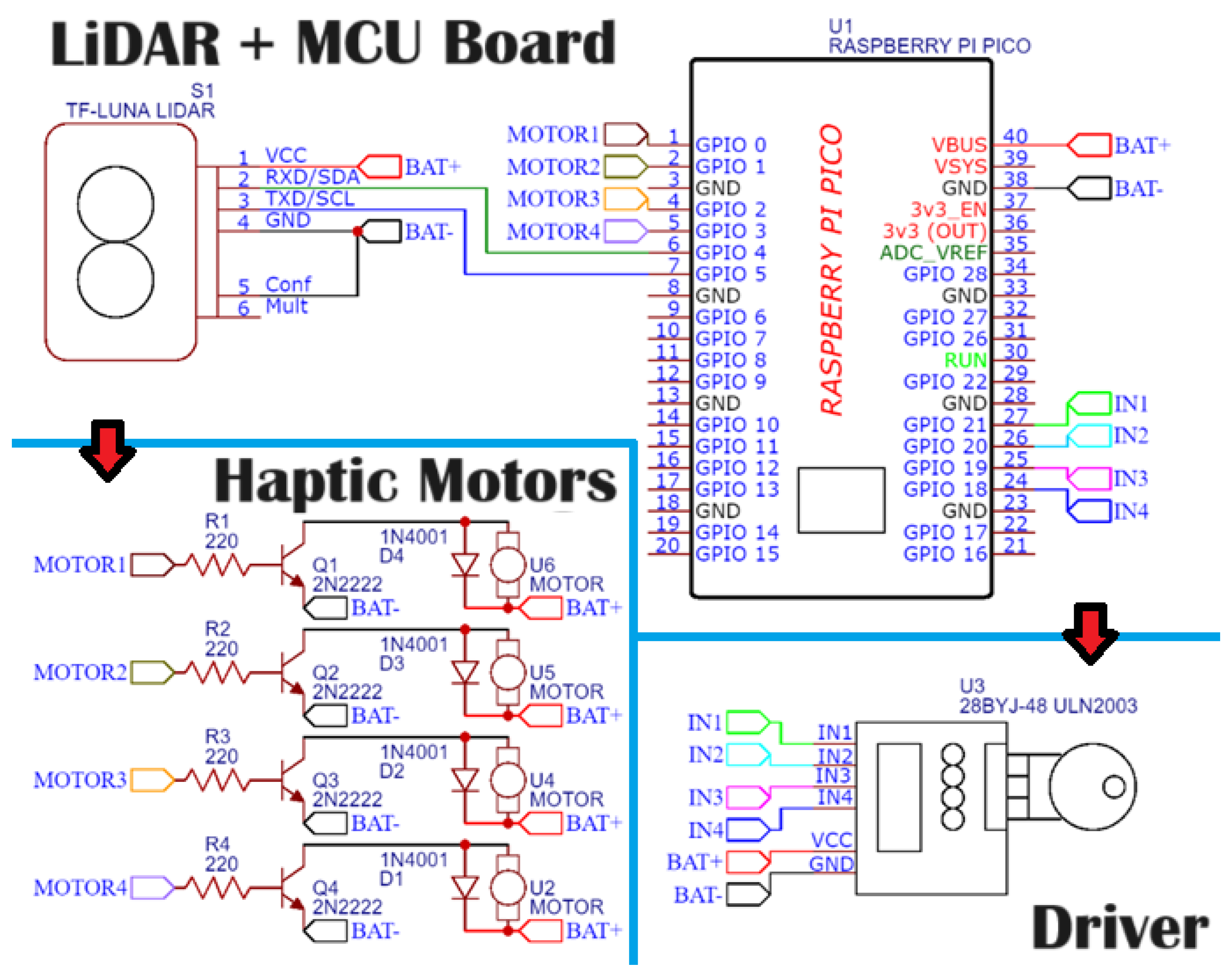
The ClaySight device is assembled, based around a commercially available TF-Luna LiDAR sensor that measures distances up to 12 m from a source position. It implements an indexed rotational system, allowing for a full circular map, similar to most radar systems. The slots on the ClaySight PCB (shown unmodified in Figure 2) and schematic in Figure 4 detail the connections between the power, microcontroller, and haptic motor slots. Figure 5 details where each electronic assembly belongs on the PCB. Figure 6 details where 4–8 motors can be placed on the appropriate slots on the PCB.

Figure 4.
ClaySight wiring diagram and hardware schematic. Lines denote wired connections between components. The LiDAR and MCU board control the driver that rotates the LiDAR sensor, as well as converting LiDAR output to directly control 4–8 haptic motors. (The detailed schematic is provided in the Supplementary Files of the paper).
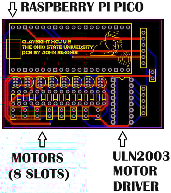
Figure 5.
Positions for mounting electronic assemblies on the ClaySight PCB. (The detailed schematic is provided in the Supplementary Files of the paper).
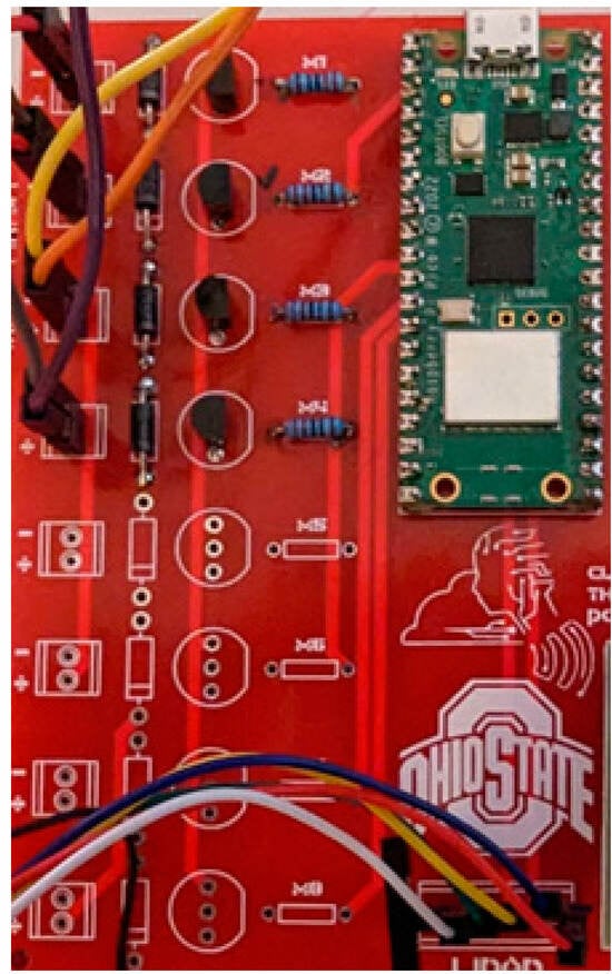
Figure 6.
Soldered PCB with 4 motors mounted and TF-Luna LiDAR attached.
3.3. Software Configuration
3.3.1. Software Installation
Software installation commences using a cable to connect the RP2040 microcontroller to a computer with an Arduino-compatible integrated development environment (IDE). The custom software is then installed on the RP2040 microcontroller to manage the logic for scanning and mapping the environment. The datalogger can also be loaded on the RP2040 in a similar manner, by physically connecting the device to a computer with an Arduino IDE.
3.3.2. Configure Mechanical Components
The program can be set to control the stepper motor’s rotation speed by executing gradual increments until one full rotation is complete. A gear multiplier of 1:3 accommodates the 28BYJ-48 motor’s low speed, ensuring accurate LiDAR sensor rotation measurements. Correct gear ratio configuration is crucial for the algorithm to properly register one full rotation of the LiDAR sensor. The PCB, battery, and electronics are located within the casing. The LiDAR sensor sits atop a smaller gear, which is turned by the primary gear attached to the aforementioned stepper motor. The proper assembly and mounting for the device are shown in Figure 7. A complete rotation takes approximately 3.2 s for the motor.

Figure 7.
Mounting and assembly for casing, gears, and TF-Luna LiDAR.
3.3.3. Data Recording
The system is programmed to record the LiDAR sensor’s distance measurements at each motor step and store these in the dynamic memory. The stored data allow for real-time localization and mapping, dividing the circular map into eight sections for averaging distance measurements.
3.3.4. Vibration and Haptic Feedback
The haptic feedback motors are connected to the microcontroller. The microcontroller converts averaged distance measurements to PWM values, controlling the vibration intensity for user alerts. Higher PWM values correspond to closer objects, causing more intense vibrations. Lower PWM corresponds to more distant objects. The specific settings can be adjusted for user comfort. Other parameters can be manually adjusted, such as the resolution distance for the LiDAR scan and a dead zone to prevent false readings from the user’s body (by default set to 10 cm around the device).
3.3.5. Debugging and Data Logging
The ClaySight data logger can send data to external computers. A USB cable is used to connect the ClaySight data logger and external system over a serial connection at 57,600 baud. The device captures all data points from the LiDAR sensor’s rotation and records them in a spreadsheet file, which can be named by the user. Data logging can be used to exfiltrate LiDAR data (e.g., for mapping). The workflow of the data logger is detailed in Figure 8.
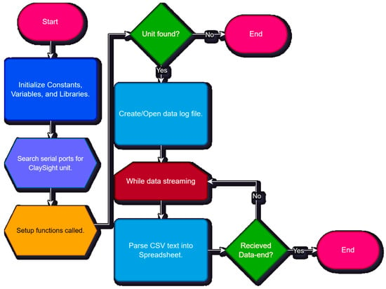
Figure 8.
Workflow to configure the data logger.
3.3.6. Safety Precautions
The stepper motor and LiDAR sensor must be securely mounted to prevent movement that may lead to inaccurate readings or mechanical failure. Careful handling of the haptic motors and LiDAR sensor is required to avoid electrical hazards or damage to the sensitive components.
3.4. User Interface and Feedback Systems
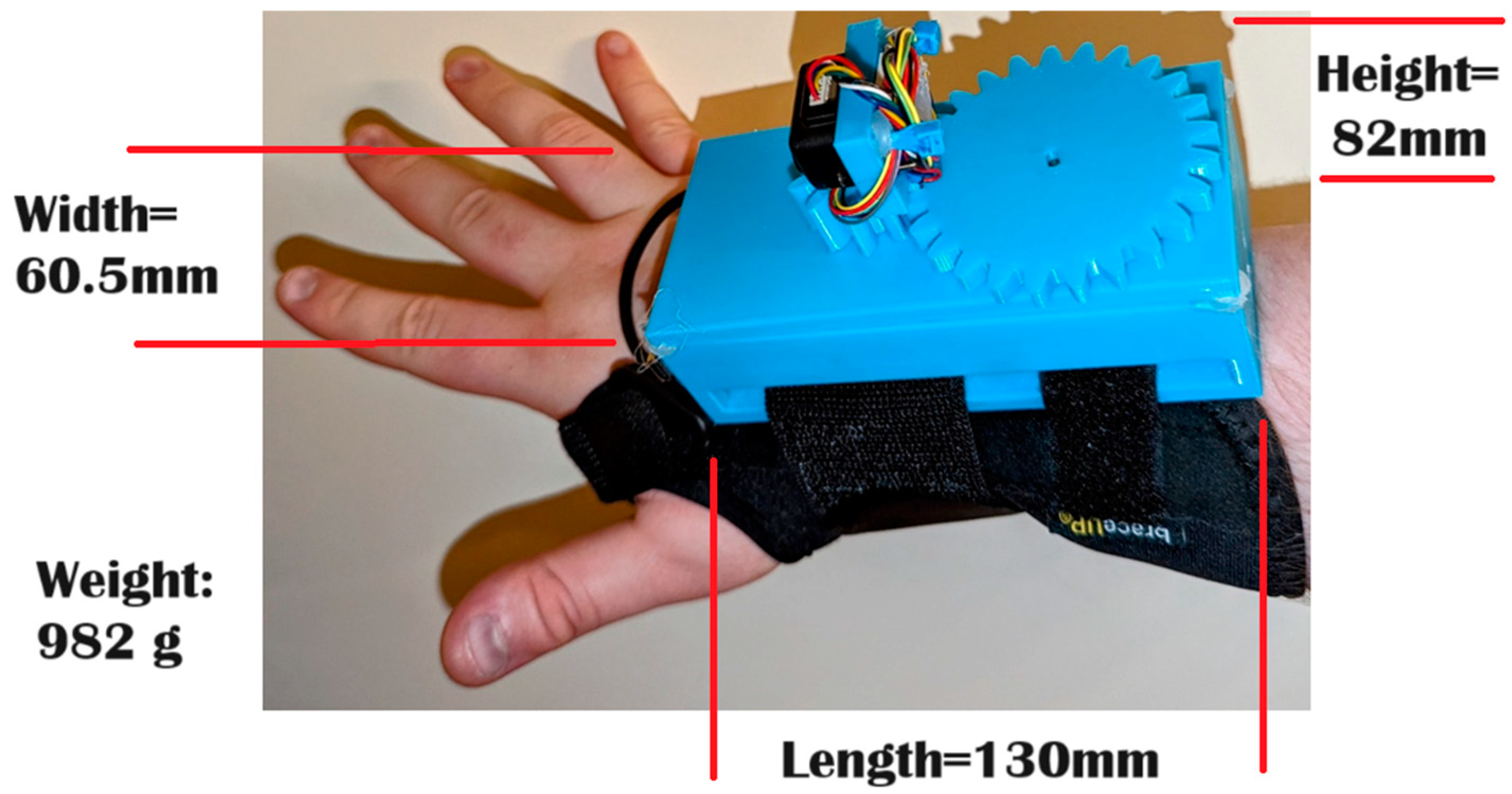
The ClaySight device generates tactile feedback based on the distance recorded by LiDAR. The feedback system is designed to be scalable; the resolution can be fine-tuned to create more or less precise tactile maps. The device is wearable and designed to be worn on the wrist or head, pressing the haptic tactile map against the skin. The final device setup is shown in Figure 9, demonstrating the LiDAR sensor-based navigation system. The assembled device has a width of 60.5 mm, a height of 82 mm, a length of 130 mm, and a weight of 982 g. The weight of the device is evenly distributed due to the positions of the straps. Mounting and wearing the device on the wrist is depicted in Figure 10.
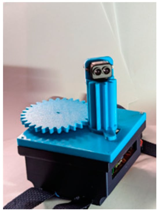
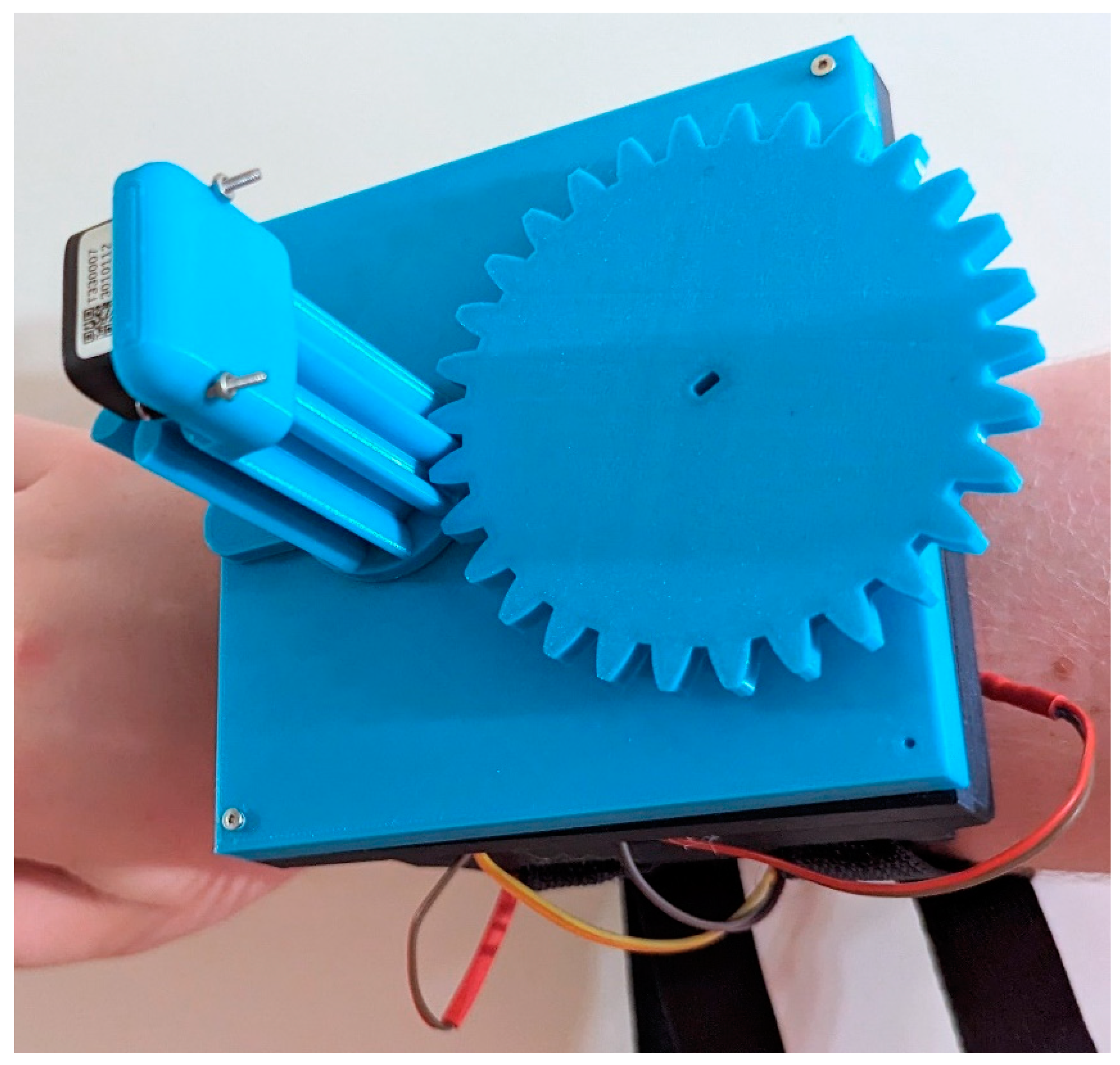
Figure 9.
Prototype of the LiDAR sensor-based navigation system.
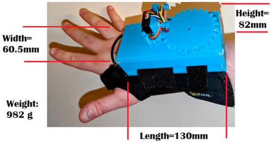
Figure 10.
Wearing the ClaySight device on the wrist.
4. Operating Instructions
4.1. Device Startup
The assembled ClaySight device should be mounted on an armband or headband, ensuring the LiDAR sensor is mounted correctly for 360° scanning. The ClaySight device is charged by connecting it to an appropriate power source. The power slots are located on the custom ClaySight PCB.
4.2. Software Initialization
First, the custom scanning and mapping software must be uploaded onto the ClaySight device’s RP2040 microcontroller. The microcontroller software controls the device’s stepper motor, managing the speed and rotation. The software parameters can be validated with physical tests, including the RPM of the stepper motor, and ensure the gear ratio of 1:3 is set correctly for accurate sensor rotation.
4.3. Scanning Environment
After the software is uploaded, the scanning feature can be activated. Upon activation, the device’s stepper motor rotates the LiDAR sensor for a full 360° scan. At the default settings, the complete rotation should take approximately 3.2 s.
4.4. Feedback System Check
The user must be familiar with the haptic feedback mechanism, controlled by PWM through the RP2040 microcontroller. The intensity of the feedback should correlate to the LiDAR distance data. The feedback system can be evaluated by moving closer to or further from an object and noting the change in vibration intensity.
4.5. Adjusting Device Settings
Specific device settings, such as the maximum scanning range and dead zone, can be customized to fit the user’s needs. The dead zone setting is integral to preventing false readings from the user’s body. The default value for the dead zone is a 10 cm radius around the device.
4.6. Datalogging Mode
The debugging mode allows data analysis or troubleshooting, initialized by connecting the device to a computer via USB. The ClaySight data-logger program then begins recording data. Once the device is correctly connected, it sends data points over the serial connection at 57,600 baud. The debugging mode is engaged in a similar manner, using a standard computer interface with a serial connection at 57,600 baud. The flowchart in Figure 4 details the data-logging procedures, and the data can be used to generate maps once exported.
4.7. Operational Test
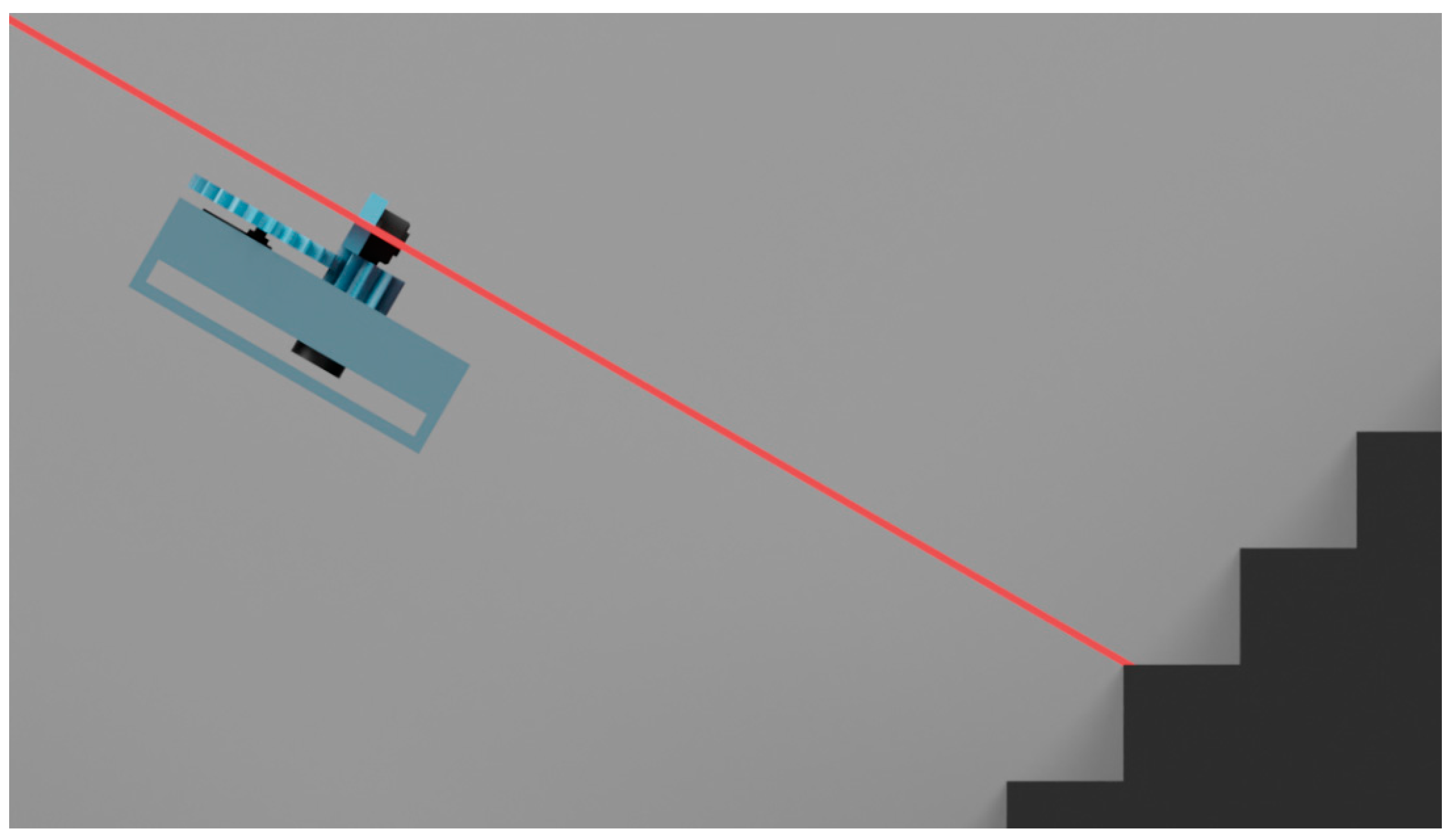
As shown in Figure 11, the ClaySight system can be systematically calibrated using a tripod with an adjustable height and angle. The device can be mounted on a tripod at a consistent height. The device should complete three scans in the debugging mode. The device’s angle should be adjusted to various inclinations from –30° to 30°, verifying its ability to accurately map and localize stairs. The test starts with the device placed at least 1 m from the wall or object. The haptic motors must vibrate most intensely within 1 m. Iterative testing is performed by moving the device back in 1 m increments, ensuring the haptic vibrations diminish at each interval. The device can also be tested on a stairwell, as shown in Figure 12.
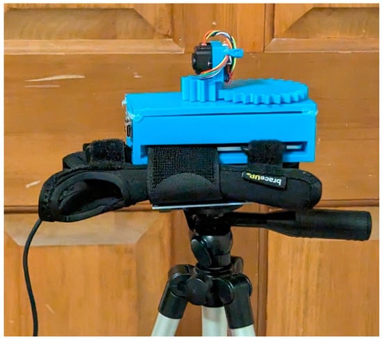
Figure 11.
Mounting ClaySight unit on a tripod for calibration.

Figure 12.
Testing the ClaySight device by angling it against a stairwell, with the laser modeled as red line.
5. Validation
5.1. Performance Characterization
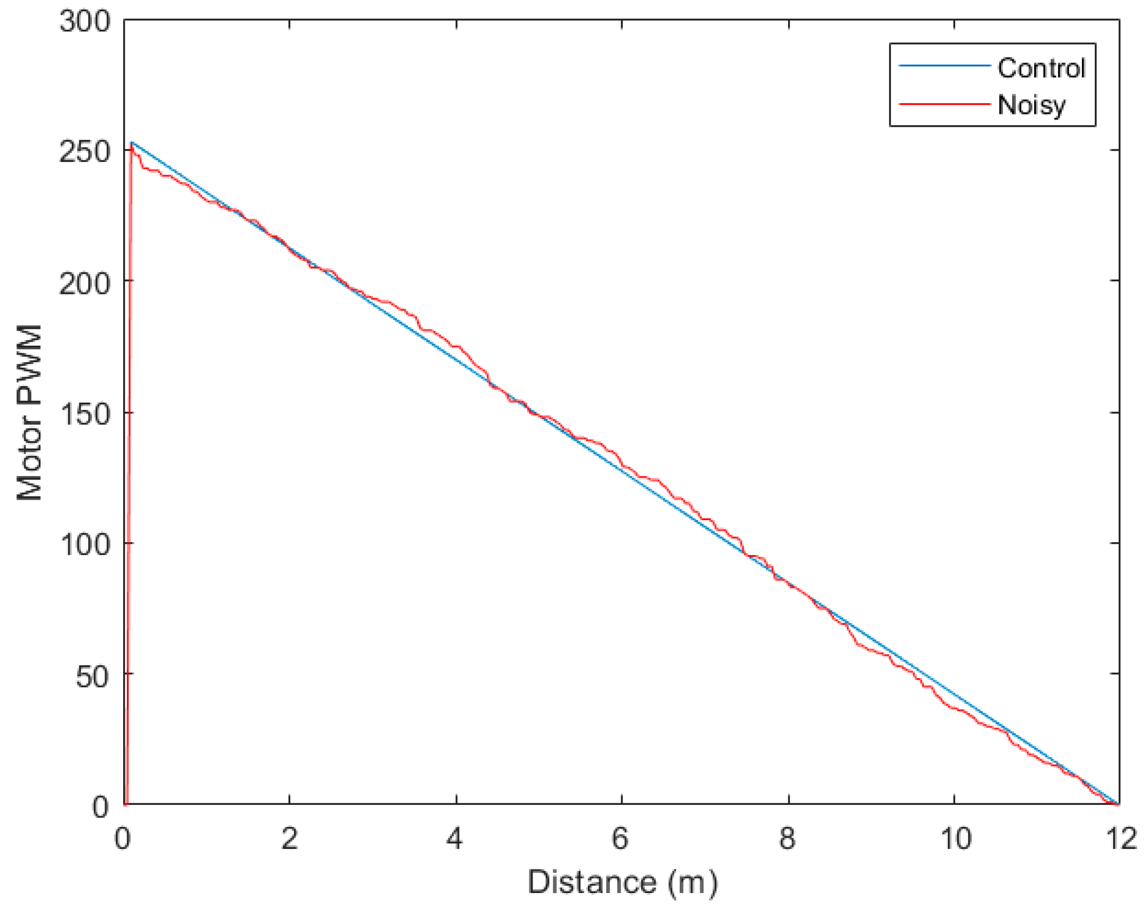
The testing setup depicted in Figure 11 and Figure 12 was used to validate the device. The device was mounted on a tripod beside a wall. The distance was incrementally adjusted, and the motor PWM was measured at both distances. The test distance was adjusted increments based on resolution, and the motor PWM was measured. The LiDAR sensor data were exported using both I2C and UART. A resolution () of 4.7 cm was used, corresponding to increment size. Each integer value could be increased up to 1024 (10-bit) values, but the default maximum PWM was set to 255 and the minimum PWM to 0. During testing, noise was generated by random moving objects (changing position within 3.2 s of each scanner sweep) within the background of the staircase. The linear relationship between measured distance and motor PWM is detailed in Equation (1), where scaling factor is the resolution in meters.
The device was tested with noise and a control case without noise. Noise included quick (<0.5 s) movements between the wall and sudden horizontal reorientation up to 30° up or down, meant to simulate active environments and moving on stairs. Tests were repeated three times under each condition. The average mean squared error (MSE) was calculated using Equation (2) [14]. In Equation (2), the total number of samples n was 255, the control case for each increment was , and the noise case was , as follows:
If the device functioned as designed, the PWM values have an inverse linear relationship with distance, outside of the “dead zone” of 10 cm.
The performance was shown in Figure 13. The observed mean squared error was 10.3 ± 2. The higher PWM indicated a closer object, while lower PWM indicated a more distant object. The low differences in PWM in the noisy case detail robustness in active environments.
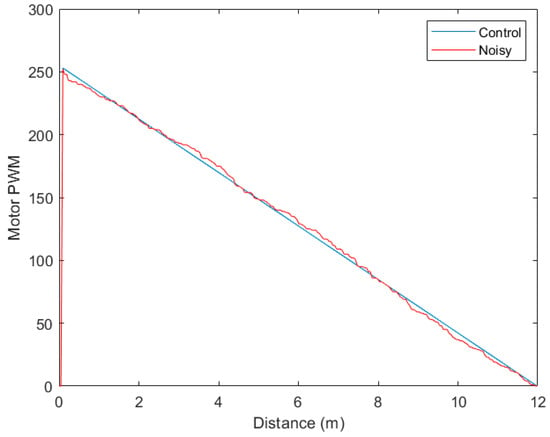
Figure 13.
Motor PWM resulting from distance measurements under control and noisy conditions.
5.2. Capabilities
The mapped intensities at multiple angles are used to estimate the distance from nearby obstacles. The wearable armband enables users to keep their hands free for daily tasks, unlike a cane or a handheld map. The low latency of the rotating LiDAR sensor enables clear and rapid vibrotactile feedback. The 360° SLAM coverage can assist users in detecting multi-height obstacles or stairs with a simple rotation of the arm.
5.3. Limitations
The current iteration of ClaySight is constrained by its bulky size, making it somewhat uncomfortable for the user. Limited memory and limited interactivity restrict the device’s capabilities. The ClaySight system cannot discriminate between stationary and moving objects. Depending on the angle the device is held, the scan may miss or omit objects that are out of range. Background movement requires a dynamic map featuring new obstacles. LiDAR data for mapping must be indirectly exfiltrated using the data logger. While the algorithm enables and compensates for edge cases, the current form only handles four directions. Rapid user movements require a “dead zone” to compensate for the body, potentially missing obstacles behind the user. Changes in height, such as stairwells, are a current limitation. Owing to the rotation speed, the system cannot detect and compensate for fast-moving objects, such as moving cars and cyclists. The device may be limited in natural environments that feature sudden changes in geography and multi-height obstacles. The device cannot store saved static maps, cannot recognize object types or directions, and depends on a stepper motor. However, the software and hardware can be readily updated and replaced.
5.4. Future Work
The current shortcomings of ClaySight can be improved through iteration. The bulky size can be reduced by optimizing the components and their placement. The stepper motor can be upgraded using a more reliable model. The resolution can be increased by refining the existing algorithm. Static maps and archived data can be stored using a memory card or other external device, in which object recognition can also be implemented. Similarly, using another LiDAR unit at a different angle, in addition to the primary unit, may facilitate the automatic detection of obstacles at different heights. Clear improvements would include integrating 3D scanning, faster rotation, a higher resolution, object tracking, and battery optimization. Regardless of technical implementation, future validation must involve visually impaired human wearers using the device to navigate a complex environment. In summary, ClaySight is an open-source, low-cost wearable that has the potential to provide a customized solution for every user over time, whether visually impaired or not (e.g., for virtual reality).
6. Conclusions
Tactile maps have long been recognized as useful tools in mobility training and the rehabilitation of visually impaired children and adults. However, these maps lack real-time versatility, and their availability is limited, owing to their high manufacturing and design costs. ClaySight is a new low-cost, open-source wearable that provides real-time vibrotactile feedback of nearby obstacles in 360°. The device comprises an armband with a stepper motor driving the rotation of a LiDAR sensor. Unlike previous devices, ClaySight enables hands-free operation while constantly scanning. Although it operates based on 2D mapping by default, the device offers multi-height obstacle detection with a simple rotation of the arm. The current iteration of the device has several limitations regarding its memory, resolution, and size, but these can be overcome, and the device will ultimately enable user-driven customization. Overall, ClaySight has the potential to enable greater independence and quality of life among the visually impaired.
Supplementary Materials
The following supporting information can be downloaded at: https://www.mdpi.com/article/10.3390/hardware2040012/s1. Claysight till of materials: Design file list; bill of materials parts list; wiring diagram.
Author Contributions
J.L.: conceptualization, methodology, and writing—original draft. Q.T.: supervision. J.S.: investigation and software. T.L.: writing—reviewing and editing. Y.Z.: writing—reviewing and editing. All authors have read and agreed to the published version of the manuscript.
Funding
This research received no external funding.
Institutional Review Board Statement
Not applicable.
Informed Consent Statement
Not applicable.
Data Availability Statement
The original contributions presented in the study are included in the article/Supplementary Materials; further inquiries can be directed to the corresponding author.
Acknowledgments
We thank the OSU Marion Honors Program.
Conflicts of Interest
The authors declare no conflicts of interest.
References
- Espinosa, M.A.; Ungar, S.; Ochaíta, E.; Blades, M.; Spencer, C. Comparing methods for introducing blind and visually impaired people to unfamiliar urban environments. J. Environ. Psychol. 1998, 18, 277–287. [Google Scholar] [CrossRef]
- Rowell, J.; Ungar, S. Feeling our way: Tactile map user requirements-a survey. In Proceedings of the International Cartographic Conference, La Coruna, Coruña, Spain, 9–16 July 2005; Volume 152. [Google Scholar]
- Amick, N.; Corcoran, J. Guidelines for the Design of Tactile Graphics. American Printing House for the Blind. 1997. Available online: http://www.aph.org/research/guides/ (accessed on 2 July 2023).
- Dixon, J. Size and Spacing of Braille Characters. Technical Report, Braille Authority of North America (Pittsburgh, PA). 2010. Available online: http://www.brailleauthority.org/sizespacingofbraille/ (accessed on 2 July 2023).
- Müller, K.; Engel, C.; Loitsch, C.; Stiefelhagen, R.; Weber, G. Traveling more independently: A study on the diverse needs and challenges of people with visual or mobility impairments in unfamiliar indoor environments. ACM Trans. Access. Comput. 2022, 15, 1–44. [Google Scholar] [CrossRef]
- Hasty, L. Tactile Graphics: A How to Guide. Available online: http://www.tactilegraphics.org/index.html (accessed on 2 July 2023).
- Jacobson, R.D. Spatial cognition through tactile mapping. Swans. Geogr. 1992, 29, 79–88. [Google Scholar]
- Miele, J.A.; Landau, S.; Gilden, D. Talking TMAP: Automated generation of audio-tactile maps using Smith-Kettlewell’s TMAP software. Br. J. Vis. Impair. 2006, 24, 93–100. [Google Scholar] [CrossRef]
- Götzelmann, T.; Pavkovic, A. Towards automatically generated tactile detail maps by 3D printers for blind persons. In Computers Helping People with Special Needs: 14th International Conference, ICCHP 2014, Paris, France, 9–11 July 2014, Proceedings, Part II 14; Springer International Publishing: Berlin/Heidelberg, Germany, 2014; pp. 1–7. [Google Scholar]
- Karkkainen, S. Touch Mapper. Available online: https://touch-mapper.org/ (accessed on 12 July 2023).
- Watanabe, T.; Yamaguchi, T.; Koda, S.; Minatani, K. Tactile map automated creation system using openstreetmap. In Computers Helping People with Special Needs: 14th International Conference, ICCHP 2014, Paris, France, 9–11 July 2014, Proceedings, Part II 14; Springer International Publishing: Berlin/Heidelberg, Germany, 2014; pp. 42–49. [Google Scholar]
- Brock, A.M. Touch the map! Designing interactive maps for visually impaired people. ACM Sigaccess Access. Comput. 2013, 9–14. [Google Scholar] [CrossRef]
- STMicroelectronics. Time-Of-Flight Sensors. 2024. Available online: https://www.st.com/en/imaging-and-photonics-solutions/time-of-flight-sensors.html (accessed on 12 July 2023).
- Bickel, P.J.; Doksum, K.A. Mathematical Statistics: Basic Ideas and Selected Topics, Volumes I-II Package; Chapman and Hall/CRC: Boca Raton, FL, USA, 2015. [Google Scholar]


Disclaimer/Publisher’s Note: The statements, opinions and data contained in all publications are solely those of the individual author(s) and contributor(s) and not of MDPI and/or the editor(s). MDPI and/or the editor(s) disclaim responsibility for any injury to people or property resulting from any ideas, methods, instructions or products referred to in the content. |
© 2024 by the authors. Licensee MDPI, Basel, Switzerland. This article is an open access article distributed under the terms and conditions of the Creative Commons Attribution (CC BY) license (https://creativecommons.org/licenses/by/4.0/).