Article

Structural and Computational Validation of a Novel Titanium Scleral Buckle Implant for Posterior Pole Retinal Detachment

by
Ahmet Turer
1,*,
Tugce Ilayda Turer
2 and
Levent Akduman
3
1
Department of Civil Engineering, Middle East Technical University, Ankara 06800, Türkiye
2
Department of Ophthalmology and Visual Sciences, Washington University, St. Louis, MO 63110, USA
3
EyeCare Partners, St. Louis, MO 63011, USA
*
Author to whom correspondence should be addressed.
J. Clin. Transl. Ophthalmol. 2026, 4(2), 11; https://doi.org/10.3390/jcto4020011
Submission received: 31 August 2025 / Revised: 19 January 2026 / Accepted: 13 April 2026 / Published: 17 April 2026

Abstract

Background: A novel titanium scleral buckle implant (TSBI) was developed for the treatment of posterior pole retinal detachments, analytically modeled and structurally tested as part of preclinical approval studies. The strength and stiffness requirements to apply pressure for retinal reattachment also suggested potential benefits for correcting high myopia greater than 8 diopters. Methods: Laboratory load testing and analytical calculations were complemented by nonlinear finite element modeling (FEM), applied for the first time to capture the interaction between the highly deformed myopic eye and the TSBI. Simulations were used to visualize posterior pole indentation and force distribution across anatomical regions. Seven TSBI units were tested in the transverse direction and six in the longitudinal direction. Results: The simulations confirmed that stable indentation is maintained even in areas distant from the sutures. The TSBI’s minimum midspan bending capacity was 40 N at yield and 60 N at ultimate. These values, together with FEM predictions, demonstrated a very large safety margin and showed that the implant deforms insignificantly under high intraocular pressure changes. Conclusions: The TSBI withstands ocular forces, cushions the sclera safely, and retains its geometry, a behavior that may differ from softer buckle materials, which can exhibit time-dependent deformation under sustained loading. Early controlled clinical applications outside the USA, followed for over three years, further validate its safety and potential effectiveness.

1. Introduction

One of the numerous tests required for any new medical device implant is performance testing, also known as bench testing [1,2]. This test is essential to demonstrate that the device can withstand the mechanical forces in the area of implantation. As part of developing a new ocular implant designed for retinal detachments involving the posterior pole of the eye, we conducted a performance (bench) test [3,4].
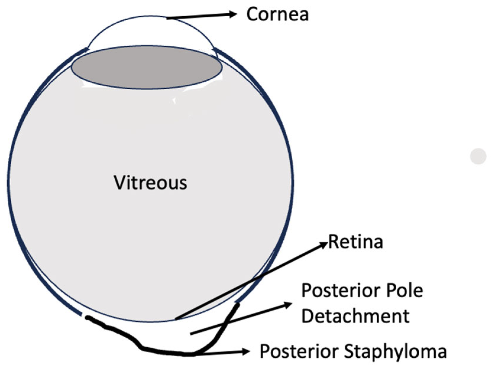
Posterior pole detachments are common in eyes with high myopia, where a posterior staphyloma (defined as an abnormal outward protrusion and thinning of the scleral wall) leads to localized bulging of the posterior globe (Figure 1) [5,6,7,8], necessitating indentation in this area to correct the underlying pathology. This clinical scenario remains particularly challenging, as highlighted in recent reviews on the management of myopic maculopathy [9]. Without proper indentation, it is extremely difficult, or even impossible, to address the detachment condition effectively [1,2,10,11,12,13,14,15]. Pars plana vitrectomy addresses retinal pathology internally by relaxing traction and allowing the retina to be stretched and reattached over a posterior scleral bulge. In contrast, a macular buckle corrects the underlying structural abnormality by externally indenting the posterior sclera, thereby reducing the bulge and allowing the retina to re-approximate and stabilize against it, with or without adjunctive vitrectomy [8,9,12,14,15]. Currently, there are limited approved implant options available outside the U.S., and none for this unmet need within the U.S., despite the increasing global prevalence of myopia [15]. Recent preliminary clinical experiences with titanium macular buckles have also demonstrated feasibility and encouraging outcomes in highly myopic eyes [16].
The titanium scleral buckle implant (TSBI) analyzed and tested in this study showed potential additional benefits, including substantial correction of high myopia (>8 diopters) while repairing retinal detachment, by pushing the staphyloma bulge inward and maintaining a stable, long-lasting shape correction. The size of the buckle concave plate was carefully selected to fill the critical gap between the eye muscle tendon and the optic nerve end, while being supported at the side of the eye by sutures. The proposed titanium implant has already been used under special circumstances in a limited number of patients across various countries, with the necessary permissions, and all trial cases have remained successful for at least three years.
Such a device is urgently needed in the U.S. to treat retinal detachment (with the additional potential benefit of correcting eyesight), which, if left untreated, can lead to blindness. The implant remains in the research stage for FDA approval, with both FEM and performance testing completed as part of this regulatory process.

2. Methods

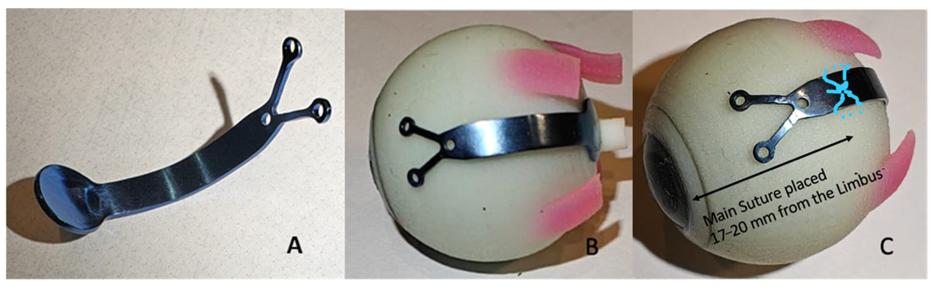
We tested 7 units as part of the performance evaluation. The design and positioning of the implant on the eye are illustrated in Figure 2A. The side view in Figure 2B shows the plate indenting the posterior pole, and the anterior view in Figure 2C shows the location of the main anchoring suture. The implant is manufactured from Ti-6Al-4V (Grade 5) titanium and finished with a medical-grade anodized surface to enhance corrosion resistance, wear durability, and long-term stability. The buckle has a uniform thickness of 0.7 mm, with a main body width of 3.5 mm and fork edges measuring 0.8 mm in width. The overall length of the implant is 21.8 mm from tip to tip. Surface profilometry of representative planar regions of the titanium buckle showed consistent sub-micron roughness, with mean areal roughness values (Sa) in the range of approximately 0.31–0.47 µm, indicating a smooth, well-finished medical device surface. The total mass of the titanium buckle is approximately 0.28 g, corresponding to less than 4% of the average mass of the human eye. The titanium buckle has a thin, low-profile geometry and is positioned beneath Tenon’s capsule, allowing the implant to move synchronously with the globe during ocular motion. Its minimal bulk and targeted posterior placement avoid contact with the extraocular muscles and excessive occupation of the orbital space, which may be encountered with bulkier designs based on soft viscoelastic materials. The implant is sutured approximately 17–20 mm from the limbus, with the primary suture stabilizing the body of the implant at its pivot point. The curved section in the posterior part, featuring a φ 7 mm diameter concave plate, provides the necessary indentation to address the bulging in the posterior pole of the eye. This bulging, the staphyloma, is the underlying cause of retinal detachment, as the retina cannot stretch sufficiently to fit the shape of the eye, leading to separation from the retinal pigment epithelium and subsequent loss of function. Various vitrectomy techniques attempting to reposition the retina from the inside have been ineffective or unnatural.
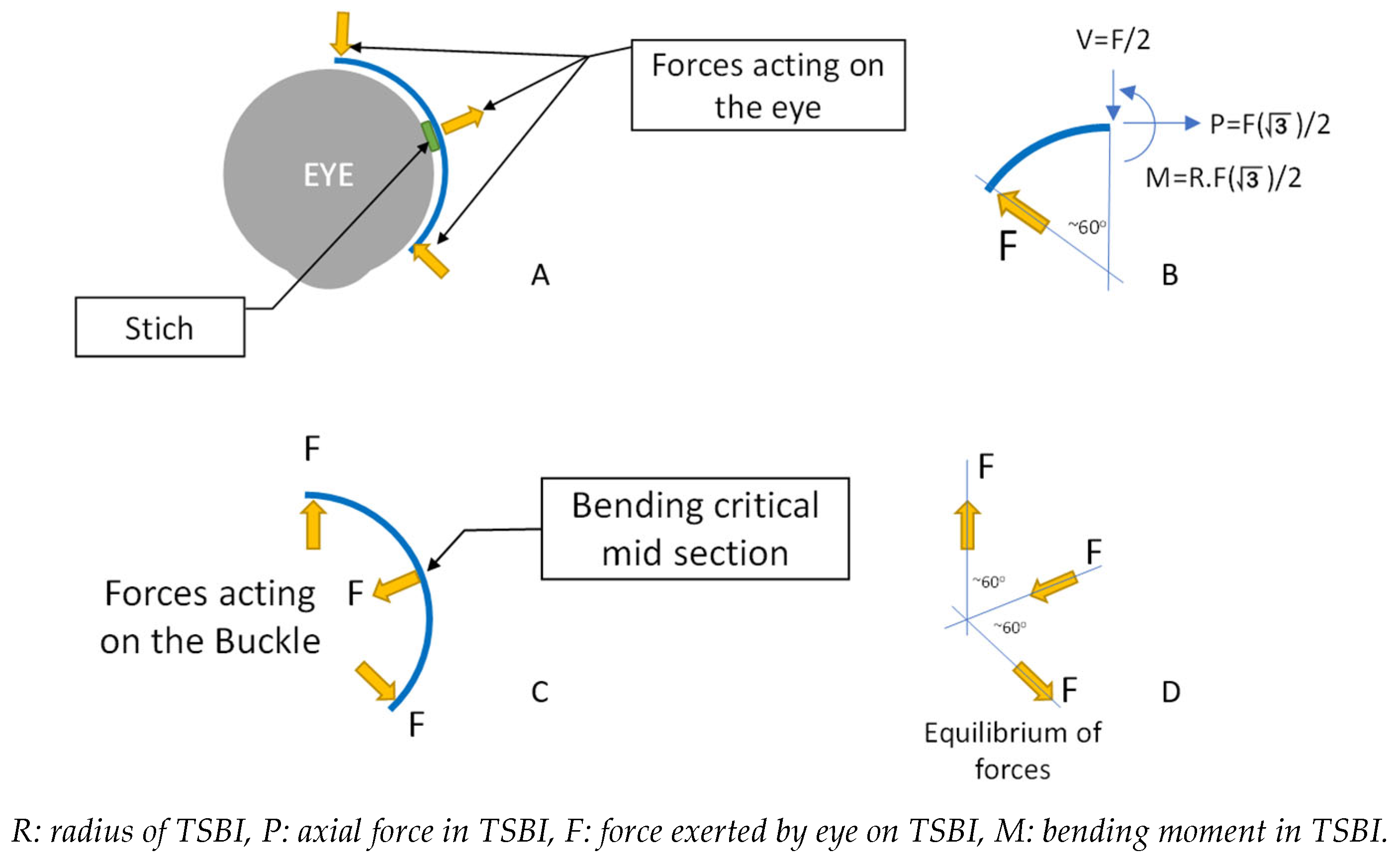
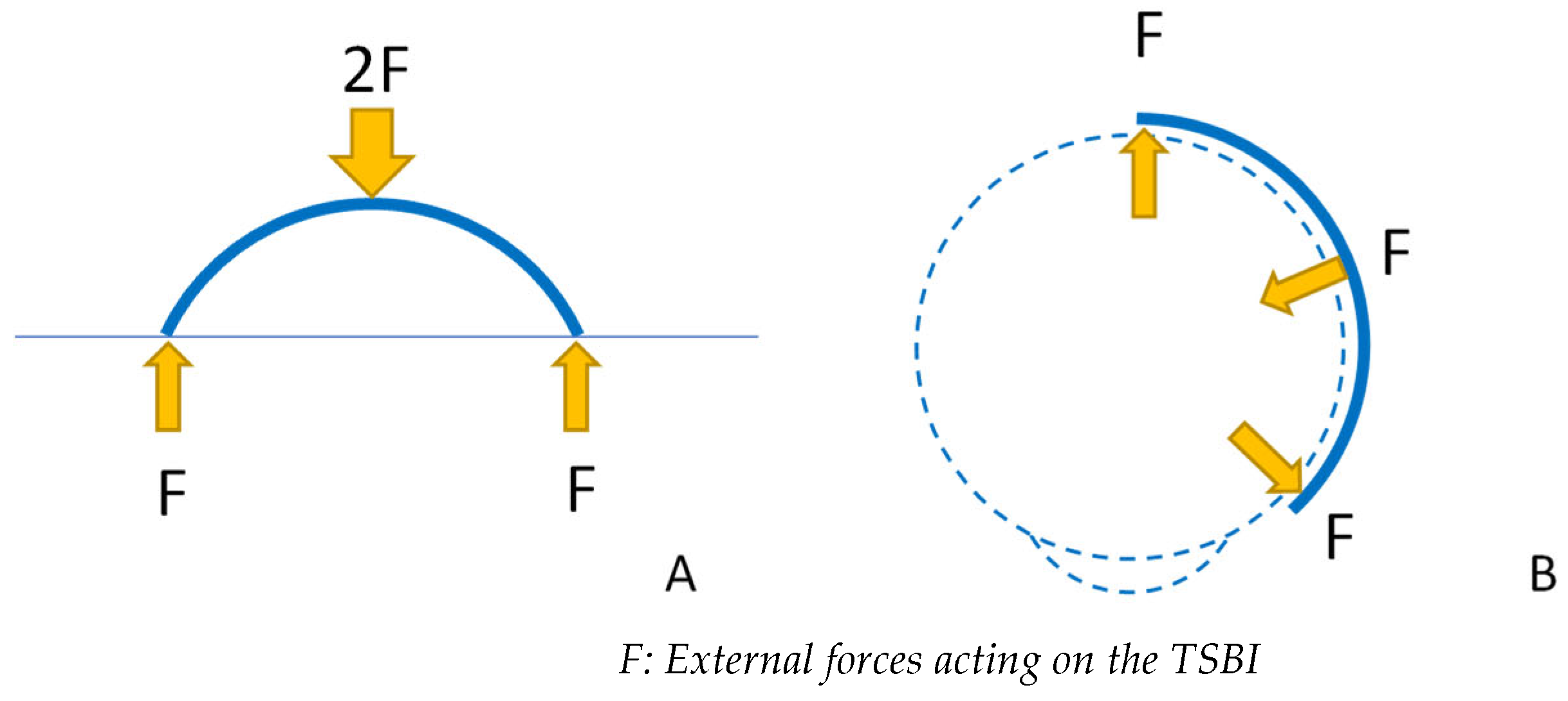
When the implant is secured to the eye with the primary suture, the plate and double-horn sections are pushed outward due to intraocular pressure. Since the implant cannot be tested on an eye with changing pressure, we developed a representative analytical model to test the implant’s bending resistance to forces applied in a similar manner. The force interaction between the eye and implant is shown in Figure 3, and our test model representation is shown in Figure 4.

3. Summary of Mechanical Design Evaluation and Testing

To ensure the long-term safety and functional stability of the TSBI, a multi-stage mechanical evaluation was conducted, combining closed-form analytical estimates, laboratory load testing, and finite element modeling (FEM). This approach was intended not only to confirm that the implant can withstand physiological loading conditions but also to demonstrate that it does so with a substantial margin of safety over its intended lifetime, without viscoelastic time-dependent deformation and with only negligible deformation under ocular geometry changes and intraocular pressure variations. Detailed engineering calculations, experimental procedures, and numerical modeling results are provided in the Appendix A, while the present section summarizes the key mechanical findings for a general readership.
First, the bending capacity of the TSBI was evaluated in both transverse and longitudinal directions using a calibrated mechanical test setup. Controlled load tests were performed experimentally to obtain and validate analytical capacity predictions. The implant was subjected to progressively increasing loads far exceeding those expected in vivo. Mechanical testing showed that the TSBI exhibited an initial transverse stiffness of approximately 45 N/mm (with a nonlinear unloading stiffness of ~19 N/mm) and a longitudinal stiffness of ~9 N/mm. Using the validated analytical capacity checks, the pressure required to initiate yielding was estimated at approximately 3958 mmHg, corresponding to a titanium yield strength of 912.9 MPa (ultimate strength 944.9 MPa). By proportional scaling, the predicted implant stress under extreme transient intraocular pressures of 100–150 mmHg is on the order of ~23–35 MPa, representing only ~2.5–3.8% of the yield strength. These results support the conclusion that the implant remains fully elastic throughout physiological loading and retains a very large margin relative to yielding and fatigue-relevant stress levels.
Simplified engineering calculations were used to estimate the magnitude of forces exerted by the eye on the implant under both normal and extreme intraocular pressure conditions. These calculations showed that forces generated by clinically relevant pressure changes are relatively small, on the order of tenths of a Newton. When these forces were compared with the measured stiffness of the titanium implant, the resulting deformations were found to be on the micrometer scale, several orders of magnitude smaller than what would be required to alter implant geometry or compromise posterior pole support. Using the experimentally measured stiffness values (≈45 N/mm transverse and ≈9 N/mm longitudinal) and the eye-induced force estimate (~0.10 N per ~20 mmHg), the expected implant deflection under extreme transient pressures remains very small, on the order of ~11–17 µm at 100–150 mmHg in the transverse direction. These micrometer-scale deformations are mechanically negligible relative to implant geometry and remain well within the elastic response range based on both the experimental and analytical results.
Nonlinear finite element simulations were used to evaluate the global mechanical behavior of the implant when interacting with the curved geometry of the eye. These simulations enabled spatial assessment of stress and deformation patterns along the implant, identifying the most highly loaded regions and confirming that stress concentrations remained below 2 MPa and well within safe limits when compared with the material capacity exceeding 900 MPa. Importantly, the simulations demonstrated that the implant behaves as a rigid, shape-stable structure under physiological loading, maintaining posterior pole indentation without time-dependent deformation, which represents an advantage over conventional softer implants.
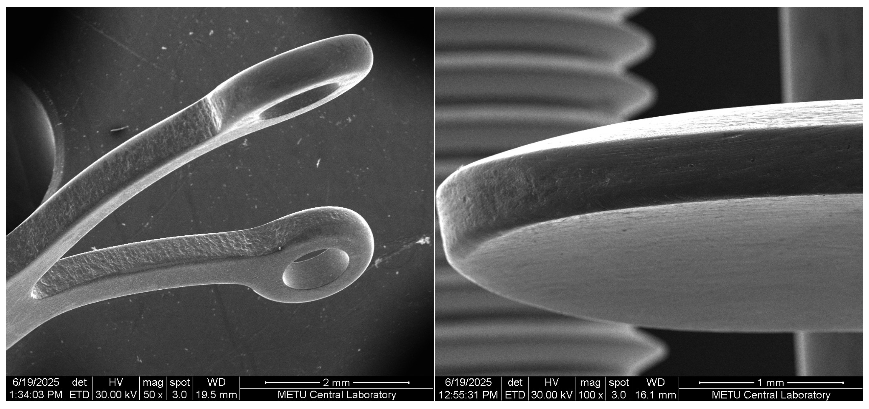
The FEM results were also used to estimate stress concentrations within the scleral tissue. The contact interface between the TSBI and sclera was modeled using discrete contact elements. While general pressure distributions could be estimated using FEM, a detailed assessment of implant edge geometry was conducted using electron microscope imaging (EMI) and supplementary analytical calculations (Appendix A.6). These analyses showed that the smoothly rounded and polished implant edges result in scleral stress levels with safety factors ranging from approximately 21 to 39. Given the reported scleral tensile capacity of approximately 1000–4000 kPa, the calculated stresses remain below 50 kPa and are well within safe limits.
Together, these complementary analyses demonstrate that the selected implant thickness and geometry provide a robust mechanical design with safety margins exceeding one to two orders of magnitude relative to eye-induced loads. By combining conservative analytical estimates, experimental validation, EMI-based edge assessment, and computational modeling, this study confirms that the titanium scleral buckle implant can reliably maintain its intended shape and function over long-term implantation without risk of mechanical failure or loss of posterior support.

4. Results

The bending capacity and stiffness of the TSBI were investigated through a series of experimental tests and analytical calculations. The study aimed to evaluate the structural performance of the TSBI under bending conditions simulating its application in ocular surgery and investigate if its strength and stiffness are adequate. The following key findings were observed.

4.1. Experimental Findings

The experimental setup was specifically designed to measure the bending response of the TSBI in both longitudinal and transverse direction loading orientations. The longitudinal orientation tests experienced stability issues, which were resolved using the transverse direction loading setup for linear range and plastic capacity using destructive testing. The results from these tests showed the following.
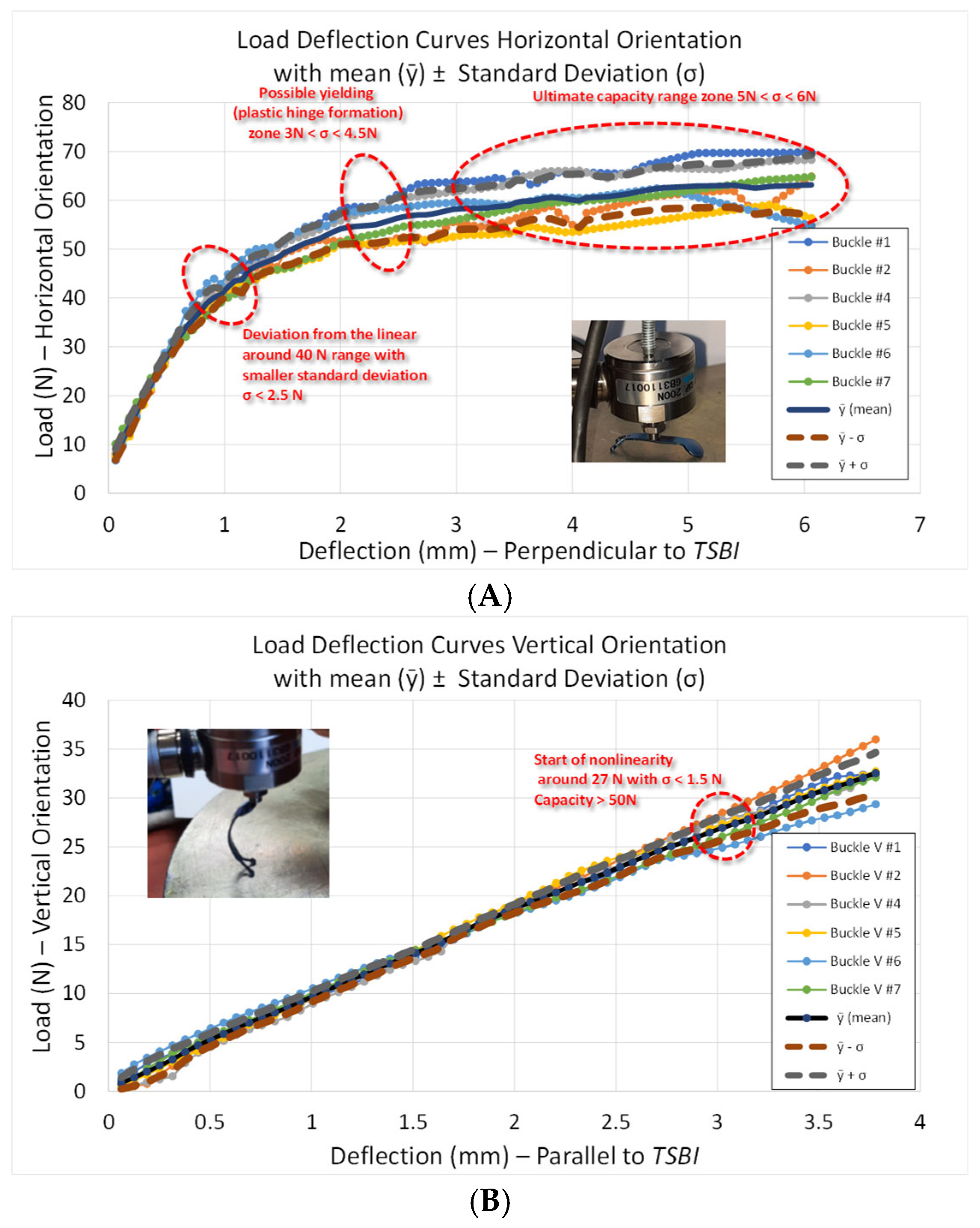
Light Weight, High Strength, and Linear Elastic Behavior: The TSBIs exhibited linear elastic behavior up to approximately 40 N in the longitudinal orientation configuration, corresponding to a stress of 923.5 MPa and outperforming the yield strain limit of 912.9 MPa from direct tension tests. The initial stiffness, recorded as 45 N/mm (Figure A4A), indicates robust resistance to deformation under expected loads. Given that the forces acting on the TSBI are expected to be around 0.10262 N for a 20 mmHg pressure change, the resulting deformation of approximately 2.3 microns (about 0.0023 mm) is negligibly small, suggesting that changes in internal eye pressure will not compromise the focal length correction, a behavior that may offer mechanical advantages over softer buckle materials. Not only the strength but also the high stiffness of the TSBI is crucial for maintaining its structural integrity and performance as an ocular implant, providing adequate rigidity without excessive deformation during both implantation and postoperative stages.
Nonlinear and Plastic Behavior: Brittle behavior, often seen in high-strength materials, is undesirable for implants. Beyond the linear range, the TSBI exhibited geometric nonlinearity, followed by a highly desirable plastic behavior. The plastic capacity is reached approximately at 65 N, and the formation of a plastic hinge maintained the force around 70 N with significant, controlled plastic deformations (Figure A4A). This performance demonstrates the TSBI’s ability to withstand forces far exceeding those expected in clinical conditions, without experiencing catastrophic or brittle failure. Considering the spread of the supports during testing, it can be concluded that the TSBI has a reserved capacity roughly double the linear range, extending beyond the 40 N range observed in testing. Furthermore, metals do not exhibit time-dependent behavior, such as creep or viscoelastic deformations, that may be faced by silicone and rubber-based materials [17,18]. This phenomenon may be further aggravated by the fact that stresses would be much closer to the material capacity in the case of silicon buckles.
Stability Issues in Longitudinal Testing: The instability observed in the longitudinal orientation during laboratory testing is not expected to occur in clinical applications, as it was a limitation specific to the testing system. The bending capacity of the TSBI was successfully evaluated using the transverse-direction load testing.

4.2. Analytical Calculations

An analytical approach was used to predict the TSBI’s behavior under simulated ocular loading conditions. These calculations provided a theoretical benchmark against which experimental results were compared. The theoretical analysis confirmed the high strength of Ti-6Al-4V (Grade 5)-based TSBIs, with a calculated bending capacity far exceeding the forces anticipated in clinical settings. Analytical calculations and experimental results demonstrated that the TSBI is approximately two hundred times stronger than the forces generated by a typical internal eye pressure increase of 20 mmHg. Even under extremely high intraocular pressure (IOP) of 100 mmHg, the TSBI provides a safety margin of more than 39.5 times, indicating a highly conservative design. This exceptional capacity, combined with its stiffness and biocompatibility, makes the TSBI an ideal system for ocular implants.

4.3. Comparison of Results

Hand calculations and FEM simulations showed consistent results in terms of the very large safety margin of the TSBI. Analytical calculations predicted maximum implant stresses around 4.84 MPa, whereas FEM localized them in the range of 1.8–2.2 MPa near the fork region. Both values are well below the yielding strength of titanium, confirming the structural robustness of the implant. For the scleral tissue, uniform stress of about 16.5–17.8 kPa is increased to near 35 kPa around the fork region. This higher value is mainly a local stress concentration, which may partly arise from numerical modeling since the sutures were represented as being tied to a single node. In reality, with multiple stitches distributed along the scleral surface, stresses would be more evenly shared and, therefore, conservatively smaller than 35 kPa.
The large overstrength of the TSBI is not only beneficial for providing a wide safety margin but also essential for maintaining the implant shape consistency under varying intraocular pressures. Compared with metallic components, softer silicone-based elastomers may exhibit time-dependent deformation (e.g., creep or tension-bending set) under sustained loading, depending on formulation and loading history [19,20]. In our analyses, the titanium buckle maintained its geometry and provided stable indentation, especially considering consistent support in posterior pole detachments. Even under conservative assumptions, the FEM and analytical results confirm that the TSBI operates safely and effectively, offering advantages over conventional materials in challenging clinical scenarios.

5. Discussion

Although titanium is a strong material and an implant made from it would likely withstand the forces exerted by the eyeball and surrounding soft tissue, it was necessary to scientifically demonstrate and prove its strength through mechanical testing. The conducted tests not only provide confidence to the manufacturer and ensure patient safety but are also a critical requirement for the FDA review process.
We aimed to develop a scleral titanium scleral buckle implant (TSBI) capable of providing stable indentation at the posterior pole of the eye [1,2]. Conventional scleral buckling systems currently approved for clinical use are predominantly based on elastomeric materials [10,21], consistent with traditional scleral indentation techniques described in classical scleral buckling surgical literature [22], and they were historically designed for equatorial support. The mechanical compliance and time-dependent deformation characteristics of such materials can impose design constraints when extended geometries or long-term shape retention are required for posterior pole indentation.
Medical-grade titanium, with its high stiffness, negligible time-dependent deformation, established biocompatibility, and decades of successful use in other implantable applications, was, therefore, identified as a suitable alternative material to expand the mechanical design envelope for posterior pole support [23,24,25,26]. The naturally forming oxide layer on titanium provides corrosion resistance and supports a favorable biological response, a combination central to its well-established long-term biocompatibility [27].
Our design enables the titanium implant to be sutured easily to the equatorial portion of the eye using anatomical locations commonly employed in scleral buckling procedures, while extending to the posterior pole to provide the necessary indentation [1,2,9]. The intuitive design of the titanium implant will allow retina specialists to place it with ease, as the surgical technique closely mirrors that used for common, softer elastomeric buckles.
Recent case reports have demonstrated successful closure of myopic macular holes using titanium buckles alone, highlighting their potential effectiveness in clinical practice [28]. Early clinical feasibility of the titanium scleral buckle has also been reported by the same surgical group in a published case series involving four highly myopic eyes with posterior pole retinal detachment, three of which were associated with myopic maculoschisis [3]. In that series, the device was used either in combination with pars plana vitrectomy or as a standalone macular buckle, with successful anatomical reattachment and resolution of maculoschisis or macular hole where present. During ongoing follow-up, no device-related complications, including buckle migration, erosion, infection, or loss of posterior indentation, have been observed. In the two eyes with pre- and postoperative measurements, the titanium macular buckle shortened axial length by approximately 2.5–3.0 mm and reduced high myopia from −13.50 to −1.50 D in one case and from −11.25 to −4.00 D in the other. These observations suggest a secondary, anatomically driven refractive effect in highly myopic eyes. Additional studies are required to determine whether this device, by reducing axial length while maintaining posterior pole shape, might also serve as a refractive treatment in this patient group [3].
From a clinical handling perspective, the titanium scleral buckle implant was designed with a thin, low-profile geometry and fixed curvature to facilitate controlled positioning at the posterior pole. The primary fixation suture is placed over the body of the implant approximately 17–20 mm posterior to the limbus, with a secondary suture placed through the central hole near the limbus to ensure positional stability. In most cases, two sutures are sufficient for secure fixation, although surgeons may elect to use all three fixation holes based on intraoperative judgment. Because the implant is placed beneath Tenon’s capsule, it avoids direct interaction with extraocular muscles and minimizes the risk of interference with ocular motility. In early clinical experience, no postoperative ocular motility disturbance or diplopia has been reported, an observation that is consistent with the implant’s thin geometry, posterior localization, and limited soft-tissue interaction.
The detailed engineering work presented here was necessary to scientifically demonstrate that the selected implant thickness could withstand all anticipated mechanical demands without permanent deformation, ensuring long-term shape stability. Based on analytical calculations, the expected eye-induced force is on the order of 0.10 N, which, when combined with the measured stiffness of the implant, results in micrometer-scale deformations that are mechanically negligible. The resulting stress levels (<2 MPa) remain far below both the elastic limit and the fatigue endurance threshold of the titanium alloy, and the loading conditions are quasi-static rather than cyclic in nature. Under these conditions, neither plastic deformation nor fatigue-related damage accumulation is expected. The absence of time-dependent deformation in titanium represents a material-level advantage when compared with viscoelastic buckle materials, particularly in applications where long-term geometric stability is required.
We developed models to simulate the forces exerted on various sections of the implant and performed rigorous mechanical testing using precise scientific methods. As shown in the Section 4, the implant’s weakest point was found to be at least 197.9 times stronger than the 20 mmHg pressure change generated forces by the eye in the linear range (39.6 times stronger compared to 100 mmHg and 26.4 times stronger compared to 150 mmHg internal eye pressure).
This study has demonstrated that titanium not only performs mechanically as an ideal material but also maintains its clinical function without deforming over the patient’s lifetime. Moreover, this research exemplifies an ideal collaboration between medical and engineering disciplines, showing how academic partnerships can drive innovative solutions. Our methods, including simulation and cross-disciplinary collaboration, provide a valuable framework for future implant design and testing.

6. Conclusions

Based on the extensive testing and analysis conducted in this study, the titanium scleral buckle implant (TSBI) is proven to be exceptionally strong, rigid, and effective. The implant’s strength and stiffness, as demonstrated by the experimental tests and extrapolated for high-pressure evaluations, ensure that it maintains its shape and function, even under extreme conditions. The TSBI can withstand internal eye pressures up to approximately 3957 mmHg (linear range and about twice in the nonlinear range), which is 26.4 times higher than the maximum temporarily elevated pressure of 150 mmHg, without experiencing deformation greater than ~17 µm. In contrast to softer elastomeric buckle materials, which may exhibit time-dependent deformation under sustained loading depending on formulation and loading history [19,20], the TSBI can be securely positioned with fewer sutures and maintains its original shape, providing consistent indentation for retinal detachment treatment. Additionally, the TSBI’s have approximately two times the reserved capacity beyond their linear range, far exceeding forces expected in clinical settings and further reinforcing their reliability and safety. Both analytical calculations and FEM simulations consistently demonstrated that the TSBI operates with a very large safety margin. The numerical results also confirmed that the implant retains its shape under physiological loading, an advantage over softer polymeric buckles, which may deform in similar conditions. This combined analytical and computational evidence reinforces the safety and effectiveness of the TSBI in the treatment of posterior pole retinal detachment.
Beyond confirming the very large safety margin, the FEM provided a visual and quantitative assessment of how the TSBI engages with the posterior pole and surrounding scleral regions. This computational approach demonstrated that the titanium implant retains its geometry and delivers stable indentation. More broadly, this study illustrates how structural engineering methods can be used to simulate surgical procedures at early stages of medical device development, when clinical testing is not yet feasible.
Although full clinical adoption awaits regulatory approval, early controlled clinical tests outside the USA have been successfully applied and monitored over three years, providing final validation of this extensive and collaborative study. Early clinical experience with the titanium scleral buckle demonstrates feasibility in highly myopic eyes with posterior pole retinal detachment. Larger, systematic studies will be required to determine whether titanium macular buckling may have a broader role in refractive modulation in addition to posterior pole support.
More recently, a multicenter peer-reviewed clinical study reporting outcomes in 11 eyes treated with a titanium macular buckle has been published [16], reporting partial or complete anatomical resolution in all cases and improvement in best-corrected visual acuity in the majority of patients. In addition, when combined with unpublished clinical experience from the same surgical group and collaborating centers, a total of 16 cases have been performed to date without observed motility-related complications.
The treated patients continue to be followed by the operating surgeons, with no device-related complications, reinforcing the mechanical performance, stability, and safety margins demonstrated by the analytical, experimental, and computational investigations presented in this study.


Author Contributions

Conceptualization, A.T.; methodology, A.T.; validation, A.T.; formal analysis, A.T.; investigation, A.T.; resources, L.A.; data curation, A.T.; writing—original draft preparation, T.I.T.; writing—review and editing, T.I.T. and L.A.; supervision, A.T.; project administration, L.A. All authors have read and agreed to the published version of the manuscript.

Funding

This research received no external funding.

Institutional Review Board Statement

Not applicable.

Informed Consent Statement

Not applicable.

Data Availability Statement

The data presented in this study are available upon request from the corresponding author. The data are not publicly available due to the format and scope of the study.

Conflicts of Interest

Dr. Levent Akduman is an employee of EyeCare Partners and is the founder and owner of LA Eye LLC, the company developing the titanium scleral buckle implant evaluated in this study.

Glossary

Approximate beam approachA simplified structural analysis method that models geometrically complex structures as equivalent beams to estimate their behavior under loads.
Bench testingTesting that approximates service conditions using conventional laboratory equipment, which may differ from the equipment used in actual service.
Bending capacityThe maximum (linear) bending moment an element can resist before the first fiber begins to yield is the largest moment before any plastic or residual deformation occurs.
Bending momentThe internal moment generated in a member due to external forces that cause it to bend.
Data acquisition system (DAS)A system that collects, digitizes, and stores data from sensors or instruments.
Finite element modeling (FEM)A numerical method that approximates the mechanical behavior of structures, enabling the prediction of deformations and stress distributions under applied loads.
Linear variable displacement transducer (LVDT)A sensor that measures relative displacement by generating a voltage proportional to the movement of its stroke.
Load cell (LC)A sensor that measures force or load by converting it into an electrical signal.
Plastic hingeA section of a structural member that has reached its ultimate bending capacity, allowing it to undergo plastic deformations and rotate indefinitely without a significant increase in the bending moment.
Reserved capacityThe remaining strength or ability of a structure or component to carry additional loads beyond its design capacity.
StiffnessThe response of a structure or member, as a bending moment or axial force, to a unit rotation or unit translational deformation, respectively.
Strain hardening effectThe phenomenon where a material becomes stronger and more resistant to deformation after being plastically deformed at higher strains.
StrainThe deformation per unit length of a material or member, caused by an applied load, stress, or temperature change.
StrengthThe maximum force, bending moment, strain, or stress a material or structure can withstand without experiencing failure.
StressThe measure of an external force acting over the cross-sectional area of an object.
Ultimate capacityThe maximum bending moment a section can carry when all its fibers have fully yielded under bending.

Abbreviations

The following abbreviations are used in this manuscript:
3DThree-Dimensional
FDAFood and Drug Administration
FEFinite Element
FEMFinite Element Modeling
IOPIntraocular Pressure
mmHgPressure unit: millimeters of Mercury
NForce unit: Newton
TSBITitanium Scleral Buckle Implant

Appendix A. Details of Analytical and Experimental Studies

Analytical and experimental studies have engineering depth, which may serve as a concept proof as well as interest readers.
Normal intraocular pressure typically ranges between 10 and 20 mmHg under physiological conditions [17,19,21]. Sustained elevations well above this range are associated with severe ocular damage and risk of irreversible vision loss [18,20,21]. Pressures on the order of 100–150 mmHg are far beyond physiological levels and are considered here solely as extreme, short-term loading conditions used to conservatively evaluate mechanical stability and safety, including the onset of nonlinear deformation and yielding behavior.

Appendix A.1. Test Setup

A custom loading setup was developed to evaluate the bending capacity of the TSBI specimens under laboratory conditions. The following instruments were employed for the experiment.
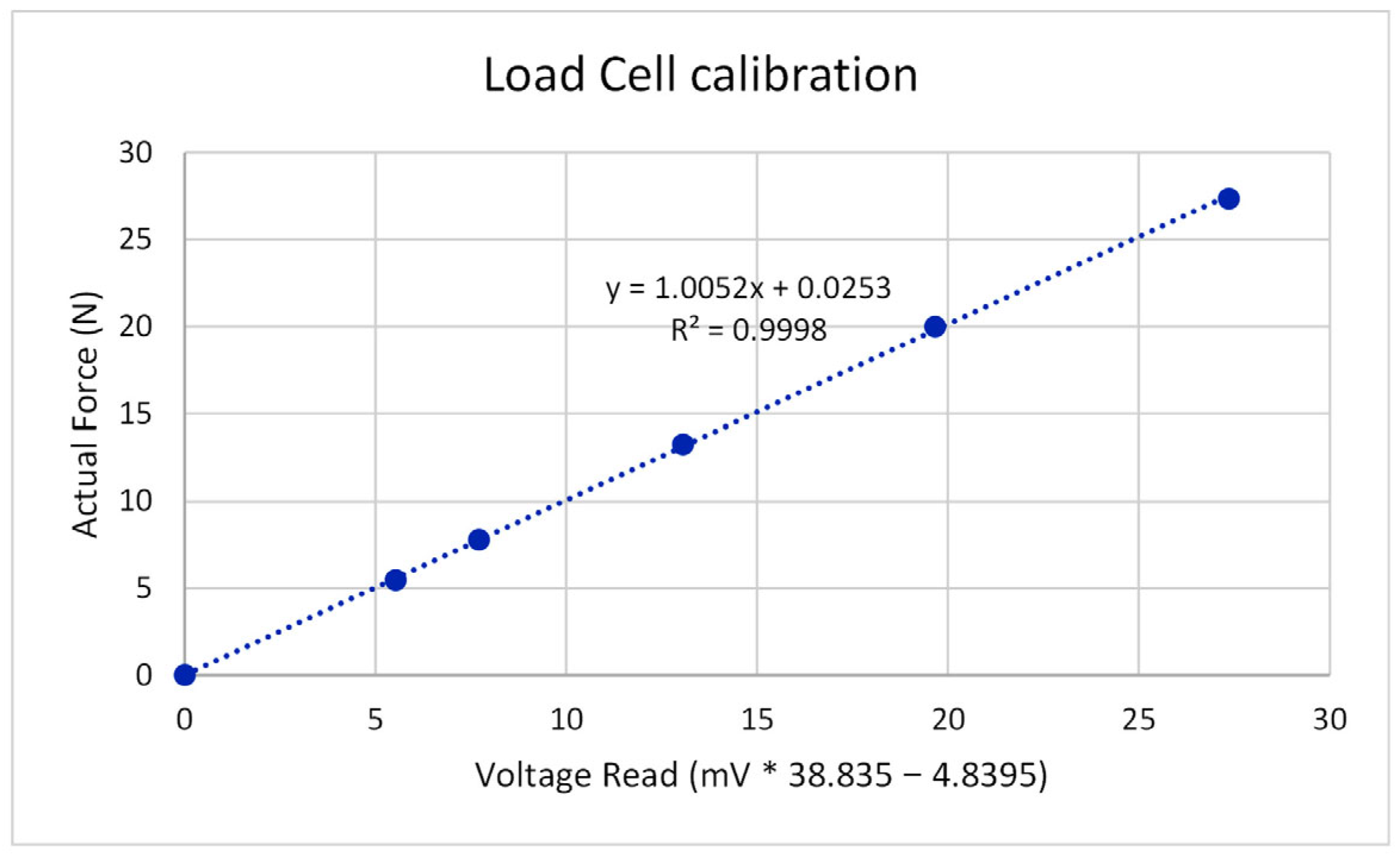
Load Cell (LC): A Kyowa brand load cell with a 200 N capacity was used to measure applied loads. The measurement range of the LC is 2.5 mV with 0.33 µV resolution. The output at full range is 1029.5 µV/V, and a 5 V input is provided. The output at 200 N range would be 5.1475 mV/200 N; therefore, the sensor factor of 38.835 N/mV is used. The calibration coefficient was tested using known forces to reveal the transfer equation as force (N) = (38.835 N/mV) × (sensor output) − 4.8395, which is successful (Figure A1), where −4.8395 N is the measurement offset.
Linear Variable Displacement Transducer (LVDT): A Prokon brand potentiometric transducer with a 10 kΩ total resistance and 10 mm stroke length was used to measure the TSBI’s response. The LVDT gives output up to 2500 mV, which means the full measurement range of 10 mm has a resolution of 10 mm × (0.666 mV/2500 mV) = 2.664 × 10⁻³ mm (2.664 microns).
Data Acquisition System (DAS): A Campbell Scientific Inc. product data acquisition system is used to digitize the collected data at a speed of four samples per second with 2.5 mV (LC) and 2500 mV (LVDT) input ranges using 50 Hz noise rejection. The DAS reads with 666 µV resolution at 2500 mV range for single-ended measurements and 0.33 µV resolution at 2.5 mV range for differential measurements.
Figure A1. Load cell calibration check using known forces.
Jcto 04 00011 g0a1

Appendix A.2. Testing Procedure

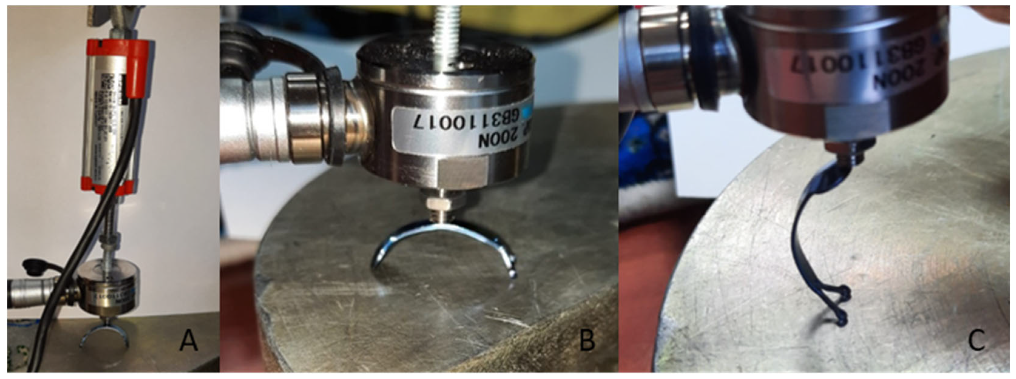
The bending capacity of the TSBI was initially predicted based on material tension tests and engineering calculations. To further verify the bending behavior, actual loading tests were conducted on the TSBIs in both longitudinal and transverse loading orientations (Figure A2). However, due to significant stability issues in the longitudinal orientation (Figure A2C), such as the tendency of the TSBI to slip or rotate, this configuration was used solely for stiffness measurements. Consequently, all linear range and destructive bending loading tests were performed in the transverse (stable) orientation (Figure A2A,B) to ensure accurate and consistent results.
Figure A2. Test setup, loading in transverse and longitudinal directions. (A) Test setup, (B) transverse testing, and (C) longitudinal testing positions.
Jcto 04 00011 g0a2

Appendix A.3. Loading Tests on TSBI Specimens and Statistical Evaluation

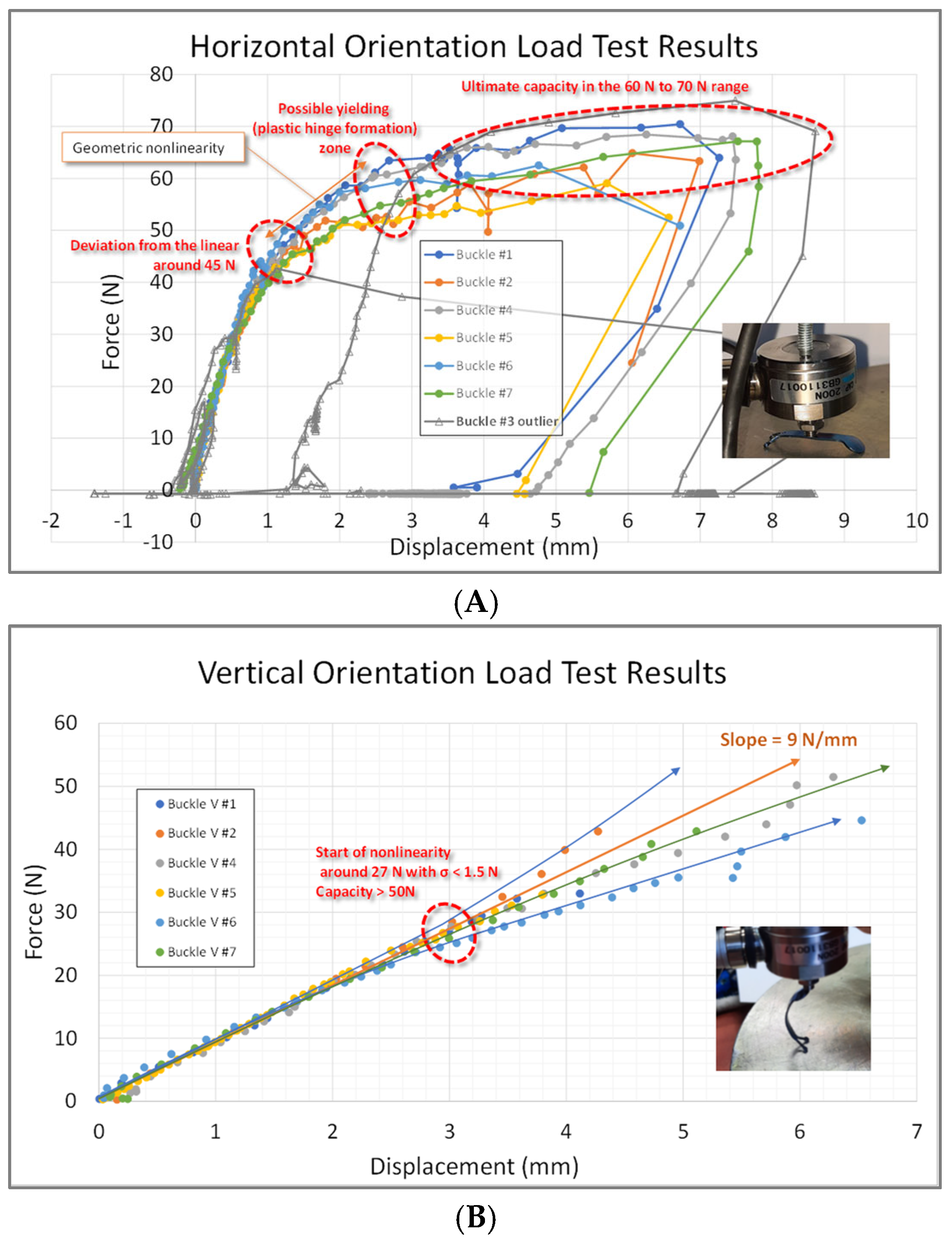
The load–displacement measurements in the longitudinal direction of the TSBI exhibited significant noise, primarily because the testing system could not adequately restrain the TSBI during testing. Often, the testing process was interrupted as the specimen dislocated. Any additional restraints on the test samples for stability would affect the test results. The data obtained from the tests yielded stiffness of about 45 N/mm during loading and about 19 N/mm during the nonlinear unloading range (Figure A3A). The stiffness of the TSBI in the longitudinal direction was about 9 N/mm (Figure A3B). The measured capacity of the TSBI in the transverse testing orientation was about 45 N (yielding) and 65 N (ultimate), while the linear range was reached at about 27 N in the longitudinal orientation (Figure A3B). Using homogenized data by interpolation, the standard deviation in the linear range is obtained to be smaller than 2.5 N (Figure A4A). As a result, most of the acquired data is clustered closely around the average. The TSBI has never been expected to exceed the linear range; however, the standard deviation reached a maximum of 5 N in the nonlinear range. The scatter observed in the nonlinear data range is associated with the test setup. The same statistical study is repeated for the longitudinal orientation, and the standard deviation in the linear range is always less than 1.5 N (Figure A4B).

Appendix A.3.1. Longitudinal Orientation Evaluation

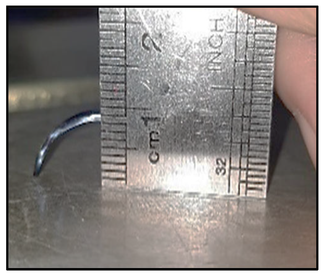
The eccentricity of the TSBI in the longitudinal direction prior to testing was about 8.5 mm (Figure A5). The axial force and bending moment contributions are considered:
P / A σ y + M / W σ y = 1
The load (P) would also generate the bending moment (M = P × 8.5 mm). Therefore, b = 3.46 mm (width) and t = 0.65 mm (thickness) would end up P/(2.249 mm2) + (P × 8.5 mm)/(0.2436 mm3) = 912.9 MPa, yielding P = 25.8 N. Longitudinal direction loading tests indicated a deviation from the straight line around 26 N as well; however, ultimate capacity did not stop at this stage and could not be accurately detected due to stability issues. This test verifies that the longitudinal linear capacity of the TSBI is about 26 N (Figure A3B). While the TSBI goes through large elastic deformations, it can withstand a relatively higher force that would not occur when installed on a human eye. While the TSBI’s longitudinal capacity when it loses linearity is considered as 26 N, engineering calculations show that a 20 mmHg increase in internal eye pressure would exert a force only in the order of 0.1026 N on the TSBI’s rounded end, perpendicular to its surface. Although these forces act in different directions and are not directly comparable, the large difference between 26 N and 0.1026 N illustrates that there is a considerable overstrength margin of the TSBI.
Figure A3. Load–displacement test results: (A) transverse and (B) longitudinal orientations.
Jcto 04 00011 g0a3
Figure A4. Homogenized statistical analysis of TSBI specimen test results in (A) transverse and (B) longitudinal orientation mean (ȳ) ± standard deviation (σ).
Jcto 04 00011 g0a4

Appendix A.3.2. Transverse Orientation Evaluation

The transverse loading position is closer to the actual loading condition when compared to the longitudinal position loading tests. The test setup of the TSBI as an arched beam had slippery supports; the loading span length expanded as the loading force increased, causing a geometric nonlinearity. Larger loads causing the supports to spread apart from each other adversely increased the moment arm and, therefore, reduced the bending capacity. As the span length and moment arm are increased, even in the material’s linear range, the load–deflection graph starts showing signs of geometric nonlinearity and then eventually plastic hinge formation, leading to a ductile failure. The full responses of the TSBI specimens are captured (Figure A3A). Theoretically, the load capacity should be constant as deformations increase after a plastic hinge formation or should even get smaller because the supports are spreading, but the measured capacity kept on increasing, probably because of the “strain hardening” effect. There might have been additional reserved capacity beyond 70 N (Figure A3A) if the tests had not stopped at about 7 mm deflection, which is a practical limit considering 8.5 mm of initial eccentricity (Figure A5).
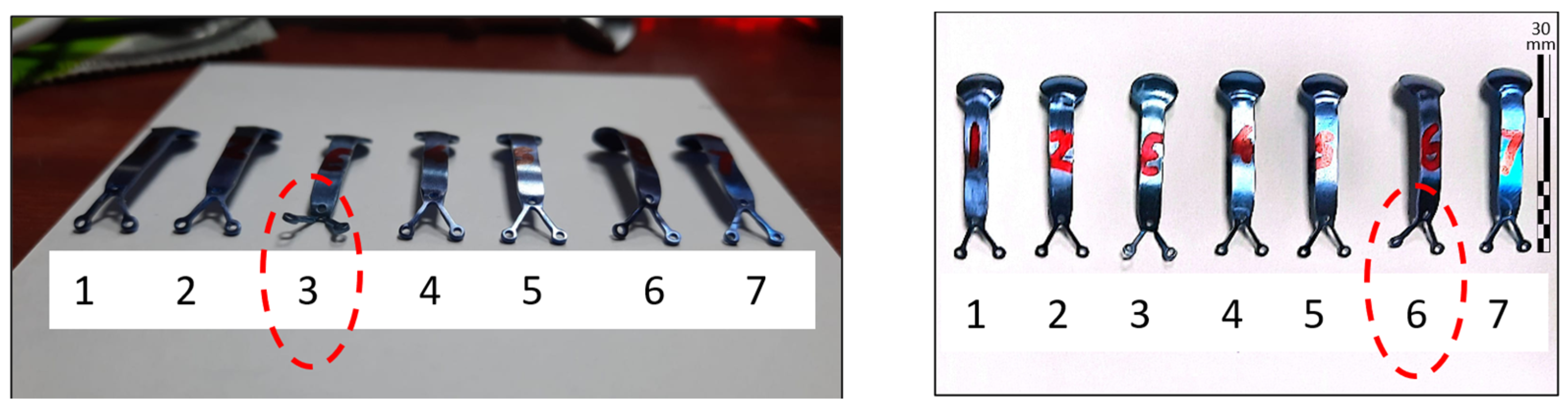
The photos of all seven specimens after the load testing are shown in Figure A6. One of the TSBI specimens (TSBI #3) had a premature failure at the fork section, and its response had a nonstandard behavior (Figure A3A). The test continued after this damage, but the results were incomparable with the others since its support conditions were changed and its data was eliminated from the statistical analysis. TSBI #6 specimen also slipped during the later stages of the loading test; however, most of the response was successfully captured (Figure A3A).
Figure A5. The eccentricity of the TSBI in the longitudinal direction.
Jcto 04 00011 g0a5
Figure A6. Post-test photographs of the TSBI specimens (circled specimens yielded inconclusive results).
Jcto 04 00011 g0a6
The testing system (Figure 4A) slightly differs from the loading conditions experienced during eye correction (Figure 4B). The reaction forces at both ends of the TSBI act parallel to the midspan force during testing, whereas all forces around the eye are assumed to be perpendicular to the TSBI because of the deformity and internal eye pressure changes. The midspan force during testing is approximately twice (2F) that of the reaction forces at each support (F) in Figure 4A, while all forces are of equal magnitude in the eye correction scenario (Figure 4B). Therefore, the test results need to be evaluated in the context of the capacity required for the eye correction case. Since all transverse loading tests were linear up to the 40 N linearity limit, the capacity calculation would be slightly adjusted to 40 N/2 = 20 N as the reaction force, given the 11.25 mm reaction-to-midspan distance; the bending moment generated during the loading tests is calculated as (40/2) N × (22.5/2 mm) = 225 N.mm. Using the bending stress calculation formula, the bending stress at the linear range limit is found to be (M = 225 N.mm)/(W = 0.24364 mm3) = 923.5 MPa.
M W = σ y
This value is very close to the material yielding test results and falls between the tested titanium yield strength of 912.9 MPa and ultimate stress capacity of 944.9 MPa (Table A1).
Table A1. Tensile test results for Ti-6Al-4V (Grade 5) titanium material used in the buckle.
Stress TypeUS UnitsSI (Metric) Units
Ultimate stress139.3 ksi960.4 MPa
134.8 ksi929.4 MPa
Yield (2%) offset stress137.3 ksi946.7 MPa
127.5 ksi879.1 MPa
Therefore, the obtained test results safely satisfy the material’s yielding and ultimate stress capacities and indicate additional reserved capacity beyond the 40 N linear test range, extending up to the 60 N to 70 N (Figure A3A), likely due to strain hardening. This significant increase in resistance is notable, considering the support spread increased the span length (L) from 22.5 mm to 28 mm in the plastic region towards the end of the loading tests. Consequently, the 60 N–70 N range should be increased by 24.4% (28/22.5) to account for the spread of the supports (M = P × L/4). In summary, the TSBIs exhibit additional reserved capacity in the plastic range, approximately 2.02 times the material capacity at the end of the linear range (65 N/40 N × 1.244 = 2.02 for support spread).

Appendix A.4. Engineering Calculations to Predict TSBI Bending Capacity

The bending capacity of the TSBI was calculated based on the material test results provided in Table A1 and engineering calculations. The interaction between the TSBI and the eye can be idealized as in Figure 3A. These forces arise from the corrective action of the TSBI as it adjusts the deformity of the eye. During the TSBI installation, the internal pressure of the eye is significantly reduced to minimize force interaction between the eye and the TSBI. As the eye’s internal pressure gradually increases to about 20 mmHg = 0.38674 psi = 2.666 kPa, a force transfer between the eye and the TSBI is expected, as shown in Figure 3C.
Structural capacity calculation of the TSBI is relatively straightforward. The curved distance between the pressure points is approximately 23 mm, and the moment arm causing bending and axial forces at the most critical “mid-section” can be calculated. A simple approach would find the bending moment to be M = (23/2 mm) × F, where F is the force caused by corrective interaction between the eye and the TSBI. Consider the diameter of the TSBI around the fovea to be 7 mm, the area to be 38.48 mm2, and the pressure to be 20 mmHg = 2.666 kPa = 2.666 × 10⁻³ N/mm2 (MPa); therefore, the force F = (38.48 mm2) × (2.666 × 10−3 MPa) is calculated as F = 0.10262 N, which is a relatively low amount of force when compared to the capacity of the TSBIs (Figure A4). The simple approach to approximately computing the bending would yield M = (23/2 mm) × (0.10262 N) → M = 1.18 N.mm as the bending moment.
The bending stresses in the TSBI caused by this action can be calculated using σ = M × c/I, where c is the distance from the neutral axis to the outermost fiber of the TSBI and I is the cross-section’s moment of inertia. The formula may be used in its simpler form by substituting W = I/c in the equation to get σ = M/W. Finally, W = I/c = b × h^2/6 as h = 2c for a rectangular section. The cross-section of the TSBI has b = 3.46 mm and h = 0.65 mm to yield W = 0.2436 mm3 and σ = M/W = (1.0973 N.mm)/(0.2436 mm3) = 4.844 MPa (for 20 mmHg pressure increase) << 912.9 MPa that was obtained at the material tests (Table A1). The approximate strength-to-demand ratio is found to be 4.844/912.9, or 188.5 times stronger.
When the internal forces are studied more accurately, the axial force, shear force, and bending moment can be calculated more accurately, as seen in Figure 3B. This time, the internal stresses need to be calculated as the combination of forces acting on the TSBI. The most critical stress condition would be affected by the axial force and the bending moment together. The capacity calculation can be linearized by the material capacity using Equation (A3).
P / A σ y + M / W σ y < 1
Here, the calculation is carried out using F × sqrt(3)/2/(b × h)/σy + [R × F × sqrt(3)/2/(b × h^2/6)]/σy, which would be (0.08887 N/2.249 mm2)/912.9 MPa + (1.1286 N.mm/0.2436 mm3)/912.9 MPa < 1. Here, the radius R is accepted as 12.7 mm. The bending test results indicated linear action up to 40 N, and the corresponding bending stress was 923.5 MPa > 912.9 MPa, corresponding to a 2% (yield) strain in the material tension tests. The smaller of the two (912.9 MPa) is used in the capacity checks to stay on the safe side, although there is additional reserved capacity.
The equation takes the form 0.03951/912.9 + 4.632/912.9 < 1 and 4.275 × 10⁻⁵ + 0.005011 = 0.00505 << 1, which means the demand at 20 mmHg is about 197.9 times smaller than the linear capacity. This approach is more accurate than the previously calculated “approximate beam” approach, where the capacity was 188.5 times larger than the 20 mmHg pressure change. The maximum pressure causing the TSBI to yield can be found as 20 × 197.9 = 3958 mmHg, which is about 39.6 to 26.4 times larger than the maximum possible temporarily high internal eye pressure of 100 mmHg to 150 mmHg, respectively.

Appendix A.5. Finite Element Method (FEM)-Based Simulations

Although the structural analysis of the TSBI can be estimated using the basic rules of structural mechanics and strength of materials, such approaches require assumptions that are intentionally conservative. The factor of safety obtained from hand calculations was in the order of 188 to 198 times the yielding capacity of the TSBI, which makes the design extremely safe. To further support this, results were also obtained using a simplified finite element (FE) model. The model was designed to be simple enough to allow nonlinear solutions to converge reliably but detailed enough to capture the overall geometry of the eye and the mechanical behavior of the implant–eye interaction. In the model, the TSBI was pressed against the already deformed myopic eye surface. The nonlinear analysis was carried out using the general-purpose structural program SAP2000 (CSI). Although the software is primarily intended for large structures, such as buildings and dams, its nonlinear solver and staged construction capabilities were adapted to simulate the TSBI and eye interaction.
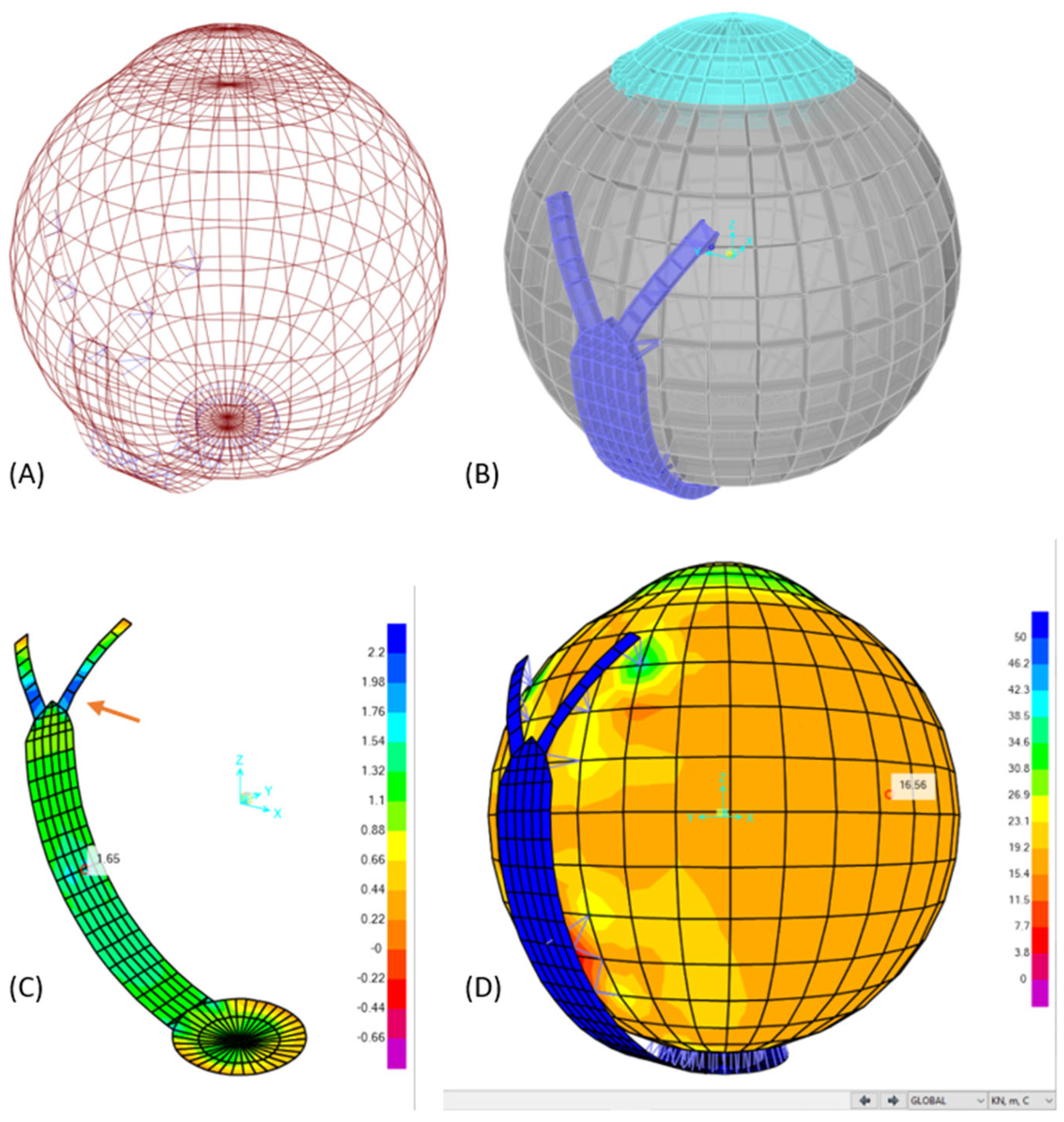
The FE model was constructed using a combination of shell elements and nonlinear link (gap) elements. The gap element permits closure of a predefined distance and then acts as a stiff spring with adjustable stiffness. The general FE model layout is shown in Figure A7A,B, and the TSBI is shown in Figure A7C. Mesh sensitivity analyses were not performed in this study. The finite element model was intentionally simplified to ensure reliable nonlinear convergence and to capture the global mechanical behavior of the implant–eye interaction. Given that the computed stress levels were orders of magnitude below the material yield limits and eye material capacity, mesh-dependent variations were not expected to affect the overall safety conclusions. Even conservative mesh-induced stress variations on the order of tens of percent would not alter the interpretation of the results, as the implant demonstrated safety margins exceeding one to two orders of magnitude under extreme loading conditions (100–150 mmHg).
Nonlinear link elements were used to represent both the eye–implant contact and the sutures anchoring the TSBI to the sclera (these appear as hair-like members in Figure A7D). The primary aim of the model was to evaluate scleral deformation under uniform intraocular pressure and to determine the resulting stresses within both the sclera and the TSBI. Accordingly, the sclera was approximated with single-layer shell elements of 0.9 mm overall thickness, acknowledging that thickness varies across regions. The scleral tissue was assigned an elastic modulus of 20 MPa and a Poisson’s ratio of 0.49 [18]. The self-weight of the eye was ignored, as the dominant loads arise from intraocular pressure (around 20 mmHg = 2.666 kPa) and the indentation from the TSBI. Several intermediate analysis stages were defined so that the gap-link elements, loads, and displacements could be applied gradually, improving nonlinear convergence and ensuring equilibrium and compatibility were satisfied at all nodes.
While hand calculations predicted maximum stresses of about 4.84 MPa in the TSBI, the FEM simulations indicated stresses of 1.65–2.2 MPa, with the highest stresses mostly concentrated around the fork region (Figure A7C) since that section is the narrowest part of the buckle. This explains why some of the test specimens suffered damage around the fork region during testing (Figure A6, #3&#6), although load was applied, causing maximum bending in the midspan. Importantly, the peak stresses at the fork region remain on the order of ~2 MPa, which is more than two orders of magnitude below the material’s yield strength (~947 MPa), confirming a substantial factor of safety. These values are still more than 400 times safe considering material capacity (Table A1), but more localized compared to hand calculation estimates. The overall scleral pressures predicted by FEM as 16.56 kPa were also safe and consistent with theoretical membrane equations: q × r/2t = 2.666 kPa × 12/1.8 ≈ 17.8 kPa. Considering that the reported tensile strengths of sclera are in the 2 to 4 MPa range [18], these stress levels are very small, at least 2000/36 = 55 times or more for 20 mmHg intraocular pressure, confirming that the corrective action of the TSBI is well within safe limits.

Appendix A.6. Electron Microscope Imaging (EMI)-Based Calculations

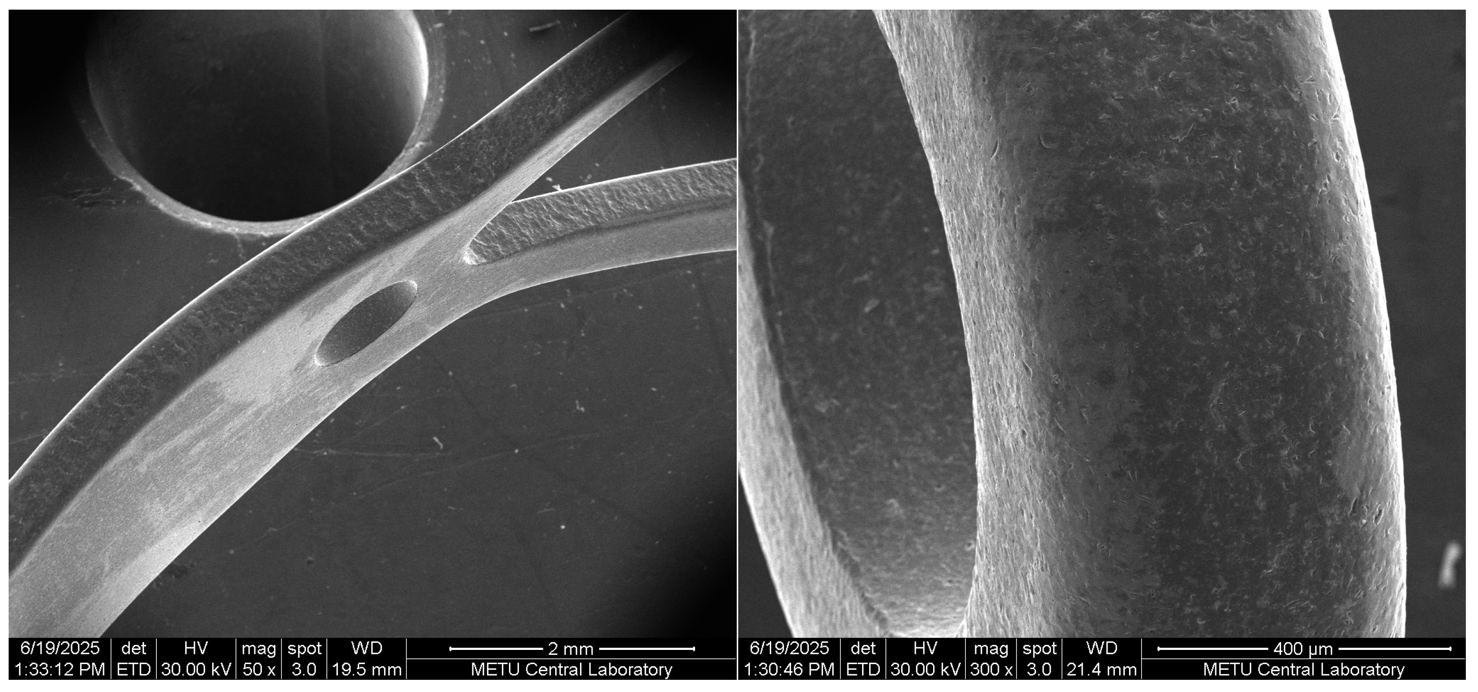
To assess potential edge-related tissue interaction risks and to support the FEM results, an EMI study was conducted on three randomly selected, sterile, ready-to-use titanium scleral buckle specimens. High-resolution Scanning Electron Microscopy (SEM) images (50×–600×) demonstrated consistently smooth, sanded, and rounded edges across all critical contact regions, including the posterior pole contact surface, fork tips, and transition zones (Figure A8). Measured edge radii were approximately 1/10 to 1/4 of the buckle thickness (≈0.07 mm minimum), with no evidence of sharp features, burrs, or manufacturing defects. Analytical estimates combining scleral tensile properties and conservative stress concentration factors indicated safety margins exceeding one order of magnitude, even under exaggerated loading assumptions. These observations confirm that local contact stresses induced by the buckle edges remain well below reported scleral strength limits and provide independent experimental validation supporting the FEM-based stress predictions presented in the main manuscript.
Figure A7. FEM simulation results: (A) FEM mesh, (B) extruded, (C) TSBI stresses, (D) scleral stresses.
Jcto 04 00011 g0a7
Figure A8. Sample EMI images of the TSBI.
Jcto 04 00011 g0a8aJcto 04 00011 g0a8b
To quantitatively assess potential edge-related stress amplification at the titanium scleral buckle–sclera interface and to independently support the FEM findings presented in the main manuscript, three complementary analytical and numerical approaches were employed. All approaches intentionally adopted conservative assumptions to bound worst-case mechanical behavior.
Approach 1: Stress-Concentration-Based Analytical Estimate
The buckle edges are uniformly rounded (sanded), allowing slight embedding into the viscoelastic scleral tissue and increasing the effective contact area, thereby reducing local stress. A conservative notch-based stress amplification model was adopted using classical stress-concentration charts (Shigley’s Mechanical Engineering Design). Main assumptions are edge radius rt/10 ≈ 0.07; scleral thickness d ≈ 0.67 mm; contact width w ≈ 0.67 mm; and resulting ratios r/d ≈ 0.1 and w/d ≈ 1.05. These parameters correspond to a stress-concentration factor Kt ≈ 1.9. Baseline scleral membrane stress under physiological IOP (20 mmHg ≈ 2.67 kPa) is σ = p × r/(2t) → (p = 2.67 kPa) × (r = 25.4 mm/2)/(2 × 0.7 mm) ≈ 24 kPa, which increases to ~46 kPa after applying the stress-concentration factor. Published scleral tensile strength measurements consistently exceed 1–4 MPa; adopting a conservative safe tensile capacity of 1 MPa, the resulting safety margin is 1000 kPa/46 kPa ≈ 21.7 times. Resulting scleral stress < safety margin/21, including stress concentration effects.
Approach 2: FEM-Based Spherical Shell Analysis
A simplified FEM shell model of a 25.4 mm diameter eye with 0.7 mm scleral thickness was used to validate analytical estimates. Theoretical membrane stress under 20 mmHg was computed using σ = p × r/2t, yielding ~24 kPa, consistent with classical shell theory. The FEM results show that the eye without a buckle has 23.2 kPa tensile stress, while the eye with a buckle has 26.9 kPa stress. The buckle, therefore, increased scleral stress by only ~3.7 kPa, remaining well below Approach 1’s conservative 46 kPa analytical upper bound.
Using the same 1 MPa scleral tensile capacity, the safety margin is more than 37 times the minimum scleral tensile capacity.
Approach 3: Geometric Deformation-Based Force Redistribution Estimate
A hypothetical inward deformation of 2 mm over a length of 6 mm scleral region was assumed to assess worst-case geometric bending effects. This deformation corresponds to an approximate 20° slope change at the buckle edge. The previously calculated buckle reaction force (0.095 N, ≈9.7 g) was conservatively distributed over a 17.6 mm circumferential contact length and 0.7 mm thickness. Resulting shear stress (~7.75 kPa), associated tensile stress (~21.3 kPa), and then combined with membrane stress (~45.3 kPa) closely match the independent stress-concentration estimate (~46 kPa), providing cross-validation. Although the literature lacks direct shear capacity tests for sclera, Tresca-type and Von Mises-type bounds can predict the lowest shear capacity in the order of 0.3–0.5 MPa range and more than 39 times safe.
As illustrated here, different approaches with combined FEM and EMI indicate that edge stresses are well within limits.

References

  1. Caplin, D.A. Implant testing and the “strain energy” concept. Plast. Reconstr. Surg. 2018, 142, 12S–20S. [Google Scholar] [CrossRef]
  2. Lovera-Prado, K.; Vanaclocha, V.; Atienza, C.M.; Vanaclocha, A.; Jordá-Gómez, P.; Saiz-Sapena, N.; Vanaclocha, L. Barbed dental Ti6Al4V alloy screw: Design and bench testing. Materials 2023, 16, 2228. [Google Scholar] [CrossRef]
  3. Akduman, L.; Ozdek, S.; Ermis, S.; Ozdemir-Zeydanli, E.; Artunay, O.; Abou Shousha, M. Myopia support device (titanium macular buckle) for posterior pole retinal detachment with or without myopic maculoschisis. J. Vitreoretin. Dis. 2025; in press. [CrossRef]
  4. Akduman, L. A titanium macular buckle implant designed for an easy placement in myopic macular holes. Retin. Cases Brief Rep. 2024, 18, 173–176. [Google Scholar] [CrossRef]
  5. Hayashi, K.; Ohno-Matsui, K.; Shimada, N.; Moriyama, M.; Kojima, A.; Hayashi, W.; Yasuzumi, K.; Nagaoka, N.; Saka, N.; Yoshida, T.; et al. Long-term pattern of progression of myopic maculopathy: A natural history study. Ophthalmology 2010, 117, 1595–1611. [Google Scholar] [CrossRef] [PubMed]
  6. Ohno-Matsui, K.; Kawasaki, R.; Jonas, J.B.; Cheung, C.M.; Saw, S.M.; Verhoeven, V.J.; Klaver, C.C.; Moriyama, M.; Shinohara, K.; Kawasaki, Y.; et al. International photographic classification and grading system for myopic maculopathy. Am. J. Ophthalmol. 2015, 159, 877–883. [Google Scholar] [CrossRef] [PubMed]
  7. Ohno-Matsui, K. Proposed classification of posterior staphylomas based on analyses of eye shape by three-dimensional magnetic resonance imaging and wide-field fundus imaging. Ophthalmology 2014, 121, 1798–1809. [Google Scholar] [CrossRef]
  8. Shimada, N.; Ohno-Matsui, K.; Yoshida, T.; Sugamoto, Y.; Tokoro, T.; Mochizuki, M. Progression from macular retinoschisis to retinal detachment in highly myopic eyes is associated with outer lamellar hole formation. Br. J. Ophthalmol. 2008, 92, 762–764. [Google Scholar] [CrossRef] [PubMed]
  9. Anderson, W.J.; Akduman, L. Management of myopic maculopathy: A review. Turk. J. Ophthalmol. 2023, 53, 307–312. [Google Scholar] [CrossRef]
  10. Radice, P.; Carini, E.; Seidenari, P.; Govetto, A. Standardized scleral buckling approach in the management of noncomplex primary rhegmatogenous retinal detachment. Eur. J. Ophthalmol. 2021, 31, 1993–2002. [Google Scholar] [CrossRef] [PubMed]
  11. Tanaka, T.; Ando, F.; Usui, M. Episcleral macular buckling by semirigid-rod exoplant for recurrent retinal detachment with macular hole in highly myopic eyes. Retina 2005, 25, 147–151. [Google Scholar] [CrossRef] [PubMed]
  12. Parolini, B.; Frisina, R.; Pinackatt, S.; Gasparotti, R.; Gatti, E.; Baldi, A.; Penzani, R.; Lucente, A.; Semeraro, F. Indications and results of a new L-shaped macular buckle to support a posterior staphyloma in high myopia. Retina 2015, 35, 2469–2482. [Google Scholar] [CrossRef]
  13. Li, J.; Li, Y.; Chen, S.; Ma, W.; Zhao, X.; Huang, X.; Lian, P.; Liu, B.; Lu, L. Outcomes of macular buckling surgery in myopic foveal detachment eyes with and without disrupted ellipsoid zone band: A case-control study. Graefes Arch. Clin. Exp. Ophthalmol. 2021, 259, 2513–2519. [Google Scholar] [CrossRef] [PubMed]
  14. Parolini, B.; Frisina, R.; Pinackatt, S.; Mete, M. A new L-shaped design of macular buckle to support a posterior staphyloma in high myopia. Retina 2013, 33, 1466–1470. [Google Scholar] [CrossRef]
  15. Parolini, B. A new model of a macular buckle and a refined surgical technique for the treatment of myopic traction maculopathy. Vision 2024, 8, 42. [Google Scholar] [CrossRef] [PubMed]
  16. Yalcinbayir, O.; Ozdek, S.; Durukan, A.H.; Shousha, M.A.; Shafy, M.S.A.A.; Sonmez, K.; Kose, H.E.; Ozdemir-Zeydanli, E.; Garg, M. Preliminary experience with a novel titanium macular buckle in the management of myopic maculopathy. Ophthalmic Surg. Lasers Imaging Retin. 2025, 56, 378–381. [Google Scholar] [CrossRef]
  17. Kohli, P.; Tripathy, K. Scleral buckling. In StatPearls [Internet]; StatPearls Publishing: Treasure Island, FL, USA, 2024. Available online: https://www.ncbi.nlm.nih.gov/books/NBK580486/ (accessed on 17 August 2025).
  18. Lee, I.; Park, J.; Jafari, S.; Demer, J.L. Tensile properties of sclera, optic nerve, and optic nerve sheath in humans with glaucoma. Investig. Ophthalmol. Vis. Sci. 2023, 64, 84. [Google Scholar] [CrossRef]
  19. Pascual-Francisco, J.; Farfan-Cabrera, L.; Sussarrey-Huerta, O. Characterization of tension set behavior of a silicone rubber at different loads and temperatures via digital image correlation. Polym. Test. 2020, 81, 106226. [Google Scholar] [CrossRef]
  20. Liu, X.; Bao, Y.-W.; Wang, X. Creep behavior of building silicone sealant under long-term external loading and its time-stress equivalence. Key Eng. Mater. 2015, 633, 451–454. [Google Scholar] [CrossRef]
  21. Steel, D. Retinal detachment. BMJ Clin. Evid. 2014, 2014, 0710. [Google Scholar]
  22. Hoerauf, H.; Heimann, H.; Hansen, L.; Laqua, H. Skleraeindellende Ablatiochirurgie und pneumatische retinopexie. Techniken, Indikationen und Ergebnisse. Ophthalmologe 2008, 105, 7–18. [Google Scholar] [CrossRef]
  23. Dux, K.E. Implantable materials update. Clin. Podiatr. Med. Surg. 2019, 36, 535–542. [Google Scholar] [CrossRef]
  24. Zohrabian, V.M.; Sonick, M.; Hwang, D.; Abrahams, J.J. Dental implants. Semin. Ultrasound CT MR 2015, 36, 415–426. [Google Scholar] [CrossRef] [PubMed]
  25. Fan, L.; Chen, S.; Yang, M.; Liu, Y.; Liu, J. Metallic materials for bone repair. Adv. Healthc. Mater. 2024, 13, e2302132. [Google Scholar] [CrossRef] [PubMed]
  26. Alsharief, A.N.; El-Hawary, R.; Schmit, P. Pediatric spine imaging post scoliosis surgery. Pediatr. Radiol. 2018, 48, 124–140. [Google Scholar] [CrossRef] [PubMed]
  27. Hanawa, T. Biocompatibility of titanium from the viewpoint of its surface. Sci. Technol. Adv. Mater. 2022, 23, 457–472. [Google Scholar] [CrossRef] [PubMed] [PubMed Central]
  28. Durukan, A.H.; Yalcinbayir, O. Successful closure of myopic macular hole with the titanium macular buckle alone. Retin. Cases Brief Rep. 2025; in press. [CrossRef]
Figure 1. Staphyloma is the root cause of posterior retinal detachment.
Jcto 04 00011 g001
Figure 2. The general view of the TSBI and positioning on the eye model: (A) the TSBI, (B) its position on an eye model, and (C) the location of the main suture.
Jcto 04 00011 g002
Figure 3. Illustration model: (A) forces acting on the eye, (B) cross-section forces, (C) bending critical section, and (D) equilibrium of forces.
Jcto 04 00011 g003
Figure 4. External forces acting on the TSBI are shown. (A) Forces (F) during load testing, (B) forces (F) during eye correction.
Jcto 04 00011 g004
Disclaimer/Publisher’s Note: The statements, opinions and data contained in all publications are solely those of the individual author(s) and contributor(s) and not of MDPI and/or the editor(s). MDPI and/or the editor(s) disclaim responsibility for any injury to people or property resulting from any ideas, methods, instructions or products referred to in the content.