1. Introduction
In this study, a continuous flow of a synthetic waste synthesis gas (SWSG) was used to produce a desalination catalyst ((Fe
0:Fe(a,b,c)@C
0)
n polymer). The process involved redox reactions [
1,
2,
3] and used both halite and Fe
xO
yH
z species as solid solutions [
4,
5,
6]. The redox reactions operated at normal temperatures and pressures (NTP). The process required the presence of a fixed bed reactor (FBR) containing halite and a saline bubble column diffusion reactor (BCDR) containing m-Fe
0 (Route 1). The passage of SWSG (containing N
2, H
2, CO, CH
4, and CO
2) sequentially through a FBR and then a BCDR converted 9.2% of the CO + CH
4 to C
0 + CO
2 (with 53% CO
2 selectivity) [
3]. This C
0 formed an Fe
0:Fe(b)@C
0 polymer within the BCDR. The placement of the polymer pellets in saline water resulted in between 30% and 60% desalination. The desalination is a pseudo-zero order reaction [
3]. This study identified an alternative manufacturing route for the production of these desalination pellets. This route is termed Route 2.
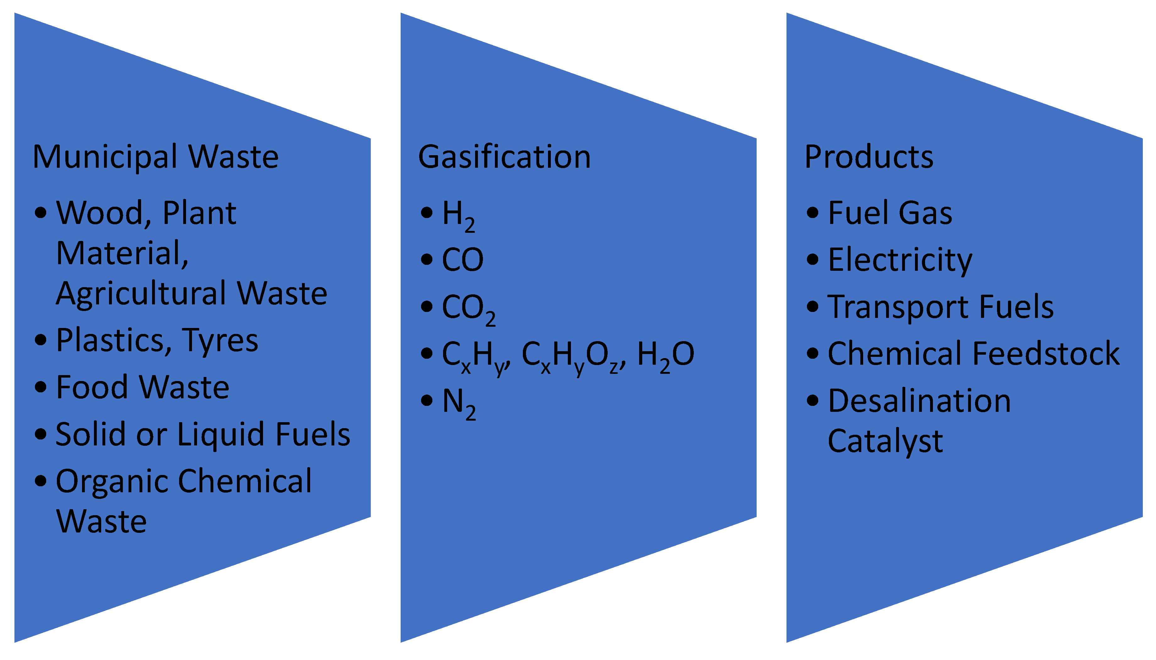
Synthesis gas (SG) is a gas containing hydrogen and carbon monoxide (
Figure 1). It can contain one or more of the following: N
2, CO
2, CH
4, C
xH
y, and C
xH
yO
z. SG is formed by the following processes: (i) partial oxidation [
7,
8]; (ii) wet reforming [
9,
10,
11]; (iii) dry reforming [
12,
13,
14]; (iv) autothermal reforming [
15,
16]; (v) hydrothermal gasification [
17,
18,
19]; (vi) pyrolysis, or partial combustion, carbonization, or gasification [
20,
21,
22,
23]. SG can be manufactured from any carbonaceous (organic) material, including municipal waste.
SG is traditionally used as: (i) fuel gas for domestic/municipal/industrial applications (town gas) [
24,
25]; (ii) feedstock for the manufacture of synthetic fuels (e.g., gas-to-liquid (GTL) processes, including Fischer–Tropsch (FT) production of synthetic natural gas [
26,
27,
28,
29], transport fuels [
30,
31,
32,
33], waxes [
34,
35,
36,
37], oxygenates [
38,
39,
40], gas-to-methanol [
41,
42,
43], and petrochemicals); (iii) feedstock for the manufacture of fertilizers [
44,
45]; (iv) feedstock for “green” power stations [
46,
47]; (v) a source of hydrogen gas [
48,
49].
The term “waste synthesis gas” (WSG) is used to describe a SG [
50] produced from the processing of municipal waste (e.g., patents KR101484919B1; KR101434246B1; AT516178A4). WSG typically contains 30–60% N
2 plus a mixture of H
2O, H
2, CO, N
2, CO
2, CH
4, C
xH
y, and C
xH
yO
z. There are >140 patents that specifically address the formation and use of WSG (e.g., patent specifications KR101484919B1; KR101482993B1; HU0800209A2; RU2459860C2; AU2009274418B2). The feedstock, SG components, and end products are summarized in
Figure 1. SG can be produced over the temperature range 370 K to 2500 K. The CO:CO
2 ratio in the WSG increases as its formation temperature increases, and it decreases as the oxidant (e.g., O
2):carbon ratio increases. A medium-to-high-temperature SG will typically contain a CO:CO
2 ratio of >1:1. A low-temperature SG (e.g., <1000 K) may contain a ratio of <0.3:1.
1.1. Desalination Using ZVI and Iron Polymers (TRL Status)
In 2008, US patent US8636906B2 established that functionalized Fe
3O
4, Fe
0, Fe(OH)
x, or FeOOH could partially desalinate saline water. In 2010–2013, bench-top continuously stirred reactors containing Fe
0 established [
51,
52] that it was possible to partially desalinate winter saline road runoff water. In 2013, patent GB2520775A established that it was possible to use WSG, SG (synthesis gas), N
2, N
2 + CO
2 combined with m-Fe
0, or n-Fe
0 to partially desalinate water. An example analysis, which is contained in GB2520775A, established that feed water containing 23.16 g Cl
− L
−1 + 15.41 g Na
+ L
−1 could produce product water containing 0.09 g Cl
− L
−1 + 0.06 g Na
+ L
−1. The solid material left in the reactor (termed ZVM TP) was found to be able to partially desalinate saline water bodies.
In 2015, Spanish patent ES2598032 [
53] established that n-Fe
0 could be used to desalinate seawater. In 2015, an academic study established that n-Fe
0-treated feed water that entered a reverse osmosis ((RO) desalination plant removed both nitrates and Cl
− ions [
54]. In 2021, a US patent (US10919784B2) established that n-Fe
0 (in the presence of an air stream) could be used to partially desalinate saline water.
The technology readiness level (TRL) for any technology can be assessed using the European Space Agency’s (ESA’s) technology readiness scale [
54,
55]. This scale grades technology into nine distinct groups, which are termed TRL1 to TRL9. Pilot desalination plants (built to comply with patent GB2520775A) with a technology readiness level of 7 (TRL7) have been constructed and operated.
This study considers a process variant for the manufacture of desalination pellets. It uses a reactor and a WSG feedstock that complies with GB2520775A. This alternative desalination pellet manufacturing route using SWSG is termed Route 2 in this paper. The technology readiness level (TRL) of the Route 2 pellet manufacturing process is TRL4/5. The TRL for the use of the desalination pellets to desalinate water is TRL2/3.
1.2. Past Patents
The typical WSG composition is summarized elsewhere [
56]. There are around 144 patents which address the formation of WSG and its applications. The majority of these patents focus on the design and operation of the carbonization retort that produces the WSG. The following patents specifically address known potentially commercial product applications for WSG:
KR101484919B1 constructs the WSG to undertake one or more of the following processes: Fischer–Tropsch (FT) synthesis, methanol production, DME (dimethylether) production, and SNG (synthetic natural gas) production;
KR101434246B1 uses (i) a CO2 adsorption process to remove CO2 from the WSG; (ii) a pressure swing adsorption (PSA) process to separate and recover H2 by separately adsorbing CO and H2;
CN113471492B uses the WSG as feedstock for a Solid Oxide Fuel Cell (SOFC), which is used to generate electricity;
RU2459860C2 uses the WSG as FT feedstock to manufacture diesel fuel; excess gas is then used to generate power;
AU2009274418B2 uses the WSG as FT feedstock to manufacture transport fuel;
BR112014004680A2 uses the WSG to manufacture aromatics and branched alkanes to produce chemical feedstock;
GB2463878B catalytically removes CO and CO2 from the WSG at NTP to produce hydrocarbons and a product gas, which is depleted in CO and CO2;
GB2520775A uses WSG to create a desalination catalyst and desalinated water.
The KR101434246B1 process uses a PSA approach to remove hydrogen. The hydrogen is then recombined with CO to produce an ideal SG (i.e., 2H
2:1 CO) for a FT process. The concept of using H
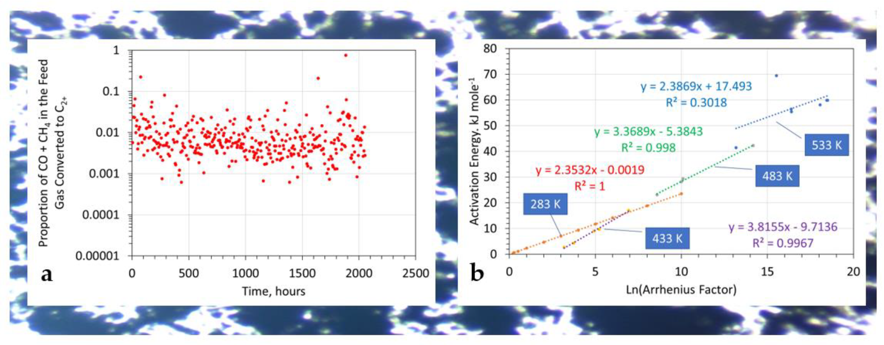
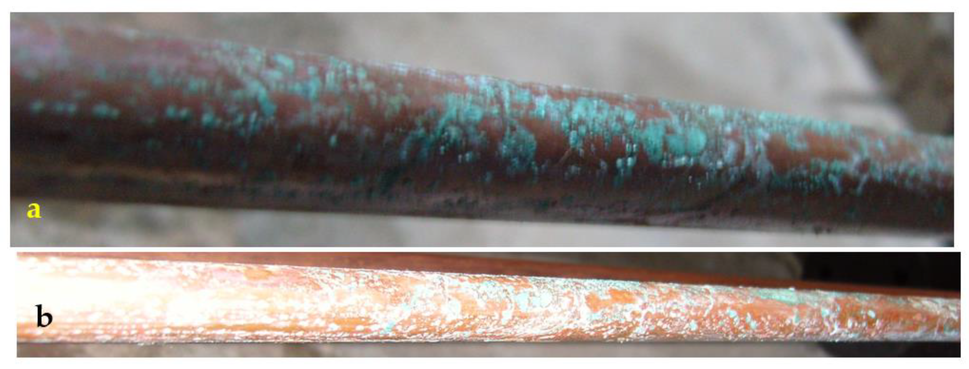
2 (contained in WSF) to maintain a reducing reaction environment (while abstracting the majority of the hydrogen) does not form part of the current patent literature. In this study, the extent and location of hydrogen seepage through copper pipes (
Figure 2) is considered. These observations were used to decide whether a future study (operated at higher flow volumes, and a larger reactor size) should separately recover the hydrogen in an outer annulus (
Figure 3).
1.3. Technical Issues Identified in the Currently Described Desalination Pellet Manufacturing Process
The technical issues that need to be considered (for the FBR) are as follows: (i) What happens to the hydrogen? In the initial manufacturing process [
3], the mass balance indicates that 16.88 H
2 = 0.89 H
2 is retained in the reactor and 15.99 H
2 is lost. The lost hydrogen either seeps through the reactor shell (about 95% of the feed hydrogen) or is placed within the reactor in another location. (ii) What happens to the carbon? In the initial manufacturing process [
3], the mass balance indicates that 3.89 CH
4 + 1.22 CO = 2.56 CO
2 + 0.08 C
2H
x + 2.39 C. C is carbon that is not accounted for in the products. It is presumed to be present as entrained C in the product gas; x = >1).
For the BCDR, the technical issues that need to be considered are as follows: (i) Is the vuggy structure of the pellets always associated with substantial excess hydrogen generation? The mass balance for the initial manufacturing process indicates that 0.89 H
2 = 12.25 H
2; this change is consistent with earlier studies [
57,
58,
59]. (ii) What happens to the carbon? The mass balance for the initial manufacturing process indicates that 1.65 CH
4 + 0.99 CO + 0.08 C
2H
y = 1.1 CO
2 + 0.18C
xH
y + 2.64 C. The carbon is present as C
0, C
xH
yO
z, HCO
3−, or CO
32−; x = >1.
Unpublished control experiments (
Section 2) indicate that the presence of carbon is required to create the desalination pellets. The creation of the three products C
0, CO
2, and C
xH
y suggests that the desalination catalyst may be a by-product of an aqueous FT process.
The unresolved technical questions are as follows: (i) whether the entrained carbon particles within the feed gas entering the BCDR are important; (ii) whether the desalination catalyst manufacturing process is a FT reaction by-product. This study provides a degree of clarification for both of these issues.
1.4. Increasing the Availability of n-C0 in WSG Entering the Bubble Column Reactor
If CH
4 is transformed to CO
2, then the initial simple assumption is CH
4 + 2H
2O = CO
2 + 8H
+ + 8e
− [
1]. Although this describes the overall reaction route, there are two intermediate reactions in an aqueous environment: (i) Reaction A: CH
4 = C
0 + 4H
+ + 4e
− [
1]; (ii) Reaction B: C
0 + 2H
2O = CO
2 + 4H
+ + 4e
− [
1].
In this study, the halite contained within the FBR was coated with m-Fe
0. This change to the process configuration in the original Route 1 study [
3] was designed to increase selectivity towards Reaction A relative to Reaction B. The reactor was placed within a RPSAD environment (as defined by patent GB2470764B) to further increase the discharged product selectivity from Reaction B towards Reaction A.
1.5. Utilising the n-C0
The hydrocarbon-generating reaction occurs at ambient temperatures using Fe
xC
y sites and Fe@C
0 sites. These sites are located both within the particles and on the n-Fe
0 particle surfaces. This reaction belongs to the aqueous FT family of reactions [
60,
61,
62]. In the aqueous environment, fresh sites are created by physically adsorbed n-C
0 [
1] and by the formation of sites associated with CO
2 [
63].
The products produced by these sites include [
63]:
Oxygenated Gases: CO2, CO, and their dissolved forms (H2CO2; HCO2−; CO22−; H2CO3; HCO3−; CO32−);
Reduced Gases: CH4; C2Hx; C3Hx; C4Hx; C5Hx;
Carboxylic Acids: HCOO−; CH3COO−; C2H5COO−; C3H7COO−; CH2(COO−)2; C2O42−;
Aldehydes: CH2O; C2H4O; C3H6O;
Alcohols: CH3OH; C2H5OH; C2H7OH.
The four insertion mechanisms proposed for product formation in a gaseous environment are the carbide, Enol, CO, and formate [
64]. These insertion mechanisms, in both the aqueous and gaseous environments, appear to be similar [
65].
In the aqueous environment, ZVI first reduces chloro-organics to C
2H
2. The C
2H
2 is then hydrogenated and polymerized to form C
xH
y and C
xH
yO
z species [
66,
67]. This allows the relative efficiency of the hydrocarbon-producing reaction (
Re) to be visualized using a normalizing equation of the form [
67]
where
ni = the number of electrons required for a stoichiometric reaction,
i = the molar proportion of the reactant converted to the product,
i;
Ct=0 = molar concentration of the reactant at time
t = 0;
Ct=n = molar concentration of the reactant at time
t =
n;
No = the number of moles of Fe
0 present at time
t = 0. The value of
ni is constant with C
2H
x species for reactions on the Fe
0 surface, where Eh is <−0.0591 pH. This relative efficiency measure assumes that the sole carbon source is contained within the feed gas stream.
In 1996, a series of control experiments in which Fe
0 (containing 2.4% C) was placed in water containing 12.3 mg HCO
3− L
−1 (at NTP) produced C
xH
y species at a slow rate (<2.76 × 10
−7 mg C
xH
y g
−1 Fe
0 h
−1) [
67].
Subsequent studies in 1997 [
68] and in 2018–2022 [
69,
70,
71] sourced the hydrocarbons from carbon contained within the Fe
0. Oxygenated products dominated the product suite [
72]. The initial FT reactions may be:
The first reaction is the production of an oxalate. The primary surface reaction, on the Fe surface, in water, takes the form [
73]:
The primary reaction is oxalate formation. The FeH
x site is created when the oxalate is desorbed [
73]. A [Fe
2+[CO]
2−] initiation site for hydrocarbon growth is created as:
Hydrocarbon generation (chain growth) at the surface sites takes the form:
Hydrocarbon desorption takes the form:
Utilizing water, the desorption takes the form:
In a gaseous FT reaction, the catalytic site is Fe
0. In an aqueous Fe reaction, the catalytic site is one or more of Fe
2+ or Fe(OH)
2+. Both carboxylate and hydrocarbon formation, within an aqueous environment, utilize the same sites [
74].
FT activation energies (
Ea) change with temperature [
75]. Below 170 °C, they are within the range 2 to 10 kJ mol
−. They have a Ln (Arrhenius factor (
Ar)) of between 0 and 4 [
76]. These values are determined [
76] from a plot of Ln(CO) conversion (y-axis) versus 1/temperature
T (K):
where
R = gas constant (8.31451 J K
−1 mol
−1);
kobs = observed decomposition of reactants to products. It follows that
where
t = reaction time (
t =
n) in minutes;
Ct=0 = the initial molar concentration of CO + CH
4 in the feed gas;
Ct=n = the molar concentration of CO + CH
4 in the product gas; (1 − (
Ct=n/
Ct=0)) = the proportion of feedstock converted to hydrocarbon.
The observed activation energy
Ea for the production of Route 1 desalination pellets can be reverse-engineered if Ln(
kobs),
T, and Ln[
Ar], are known [
76], i.e.,
where for Ln(Arrhenius Factor (
Ar)) = 3, the calculated average
Ea = 7.01 kJ M
−1; for Ln(Arrhenius Factor (
Ar)) = 4, the calculated average
Ea = 9.41 kJ M
−1. These values are consistent with the hydrocarbon production process, as they are part of the FT family of processes. The relationship between
Ea and Ln(
Ar) for both gaseous FT reactions and the formation of desalination pellets is provided in
Figure 2 as a function of temperature. The resultant product, which is contained in the desalination pellets, is a [Fe
0:Fe(a,b,c)@C
0]
n polymer.
1.6. Study Objectives
The Route 1 desalination pellet manufacturing process uses two reactors arranged in series. The first reactor (FBR) contains NaCl + silica gel. The second reactor (BCDR) contains water, NaCl, and Fe0.
This study sought to:
- (i)
increase the amount of entrained n-C0 produced in the FBR and transferred in the product gas to the BCDR, and
- (ii)
examine whether transferring the main point of n-C0 production to the FBR will result in the formation of a desalination catalyst and whether it will convert the BCDR from a net remover of CO + CH4 to a net producer of CO, CO2, and CH4. Both observations should occur if the aqueous FT model of CxHy and CxHyOz production is a viable hypothesis.
If both observations can be shown to be true, then three potentially commercial avenues of investigation will open up:
First, an alternative reaction route for the formation of the desalination pellets within the BCDR will have been identified.
Second, the desalination pellet composition could potentially be changed from Fe0:Fe(a,b,c)@n-C0 to C0@n-Fe0:Fe(a,b,c). In this instance, the dead-end porosity used to sequester the removed NaCl is switched from the dead-end pores within the Fe(a,b,c) polymer to dead-end pores within the C0. This approach would allow the active carbon produced from the processing of municipal waste or another carbon source to be utilized. This may provide a substantially cheaper and easier to manufacture pelleted desalination catalyst. A single experiment is provided to indicate whether this route may have merit for further investigation.
Third, hydrocarbon formation in the gaseous environment would be linked to tethered carbon (Fe:C). The production of CH4 and CO, would confirm that in an aqueous, redox, and diffuse environment, the carbon (for aqueous FT processes) need not be tethered. It can be physically adsorbed, i.e., Fe@C. This may allow, following further investigation, active nano-carbon produced from the processing of municipal waste or another carbon source to be utilized to provide a substantially cheaper, aqueous, and FT-like process that can operate at ambient temperatures.
2. Materials and Methods
The polymer terminology and the definition of Fe polymers are provided in references [
77,
78,
79,
80]. A Fe:Fe(a,b,c)@C
0 desalination catalyst has a layered structure in which the innermost layer is Fe
0. It has a chemically bonded corrosion surface of Fe(a,b,c) polymer (iron oxyhydroxides). The outer surface contains physically adsorbed n-C
0.
2.1. Control Studies Undertaken Prior to the Commencement of This Study
The placement of Fe
0 into saline water results in the iron corroding [
1,
81,
82,
83]. The Fe corrodes to form both ions and Fe
xO
yH
z polymer products [
1,
82,
83]. The corrosion reaction is exothermic [
84,
85,
86]. The oxyhydroxide polymers reduce the salinity of the water. The Cl
− ions are either incorporated into the oxyhydroxide structure (e.g., chloride green rust [
87,
88,
89,
90]) or occupy structural molecular pores within the oxyhydroxide structure (e.g., akageneite, FeOOH [
91,
92,
93,
94]). In each of these two examples, the maximum molar removal of Cl
− ions is around 0.15 M Cl
−: 1 M Fe. Ion removal with both green rust and akageneite can be evaluated using standard adsorption analysis techniques [
95,
96,
97,
98].
The maximum molar removal of Na+ ions + Cl− ions using the desalination pellets can exceed 4.7 M NaCl: 1 M Fe. The removed NaCl is sequestered as NaCl within dead-end pores contained within the pellets. The pellets operate by adsorbing ions from the water and sequestering them into the dead-end porosity.
Prior to the commencement of this study, a number of unpublished control trials were undertaken. These control trials used the Route 1 reactors and operating conditions. They were designed to determine if the composition of the pressurizing gas was an essential requirement to produce the desalination pellets.
Control Experiment 1. Pressurising gas: air (and not WSG). The product oxyhydroxide was pelleted, and 300 g of pellets was placed in 10 L saline (10 g NaCl L−1) water at NTP. The water was left for 300 days before being reanalysed. No reduction in water salinity was recorded.
Control Experiment 2. Pressurising gas: nitrogen (and not WSG). The product oxyhydroxide was pelleted, and 300 g of pellets was placed in 10 L saline (10 g NaCl L−1) water at NTP. The water was left for 300 days before being reanalysed. No reduction in water salinity was recorded.
Control Experiment 3. Pressurising gas: a mixture of 80% N2 and 20% CO2 (and not WSG). The product oxyhydroxide was pelleted, and 300 g of pellets was placed in 10 L saline water at NTP. The water was left for 300 days before being reanalysed. No reduction in water salinity was recorded.
These observations indicate that the presence of one or more of H2, CO, and CH4 (WSG) in the pressurizing gas was an essential feedstock component.
2.2. Iron Powder Compositions
In this study, the same m-Fe0 source that was used to construct the original Route 1 desalination pellets was used. The supplier indicated that >70% of the particles were <40 microns (Fe total = >93%; Fe0 = >87%).
The powders used in this study were Q235C/U12358 grade (Chinese Standard GB/T 700-2006). When fresh (i.e., when manufactured), they contain <0.17 wt % C; <0.35 wt % Si; <1.4 wt % Mn; <0.04 wt % P; <0.04 wt % S; <0.3 wt % Cr; <0.3 wt % Ni; <0.3 wt % Mo; <0.3 wt % Cu. The balance is Fe0, FexO2, and FexOyHz.
No analyses of BET surface area (expected to be <1 m2 g−1) or chemistry (XRD, XRF, etc.) were undertaken for the catalyst ingredients or the products.
2.3. Hydrogen
All of the reactors and the conduits used in the reactors were constructed from copper with brass fittings. At operating pressures above 0.17 MPa, some of the hydrogen contained within these pipes will leak through the external pipe walls. An example of prolonged hydrogen leakage through a reactor conduit wall (15 mm O.D.) is provided in
Figure 3. In this study, H
2 was used to maintain reducing conditions within the reaction environment. It was not assumed to be a primary reactant. Consequently, a high level of hydrogen conduit leakage (up to 95%) was tolerated.
The permeability of copper to hydrogen is addressed elsewhere [
99,
100]. The presence of NaCl enhances this permeability by 1 to 2 orders of magnitude [
101].
2.4. Reactor Shell Structure
The desalination pellet manufacturing process creates two primary products: (i) a solid desalination metal oxyhydroxide polymer; (ii) hydrocarbons. CO2 is an unwanted waste product.
Copper tubing acts as a hydrogen-selective membrane (
Figure 4) under the reaction conditions. Therefore, by constructing the reactor with a dual annulus in accordance with patent GB2475479B, it is possible to:
Maintain a reducing environment within the inner annulus (
Figure 4)
Remove excess hydrogen into the outer shell (and outer annulus) to create a high-purity hydrogen gas stream (
Figure 4)
This conceptual reactor design allows it to be placed in a borehole, a trench, or a waterbody, or on the ground. In order to meet regulatory constraints, in most regions, the reactor will be placed within a bunding shell (
Figure 4).
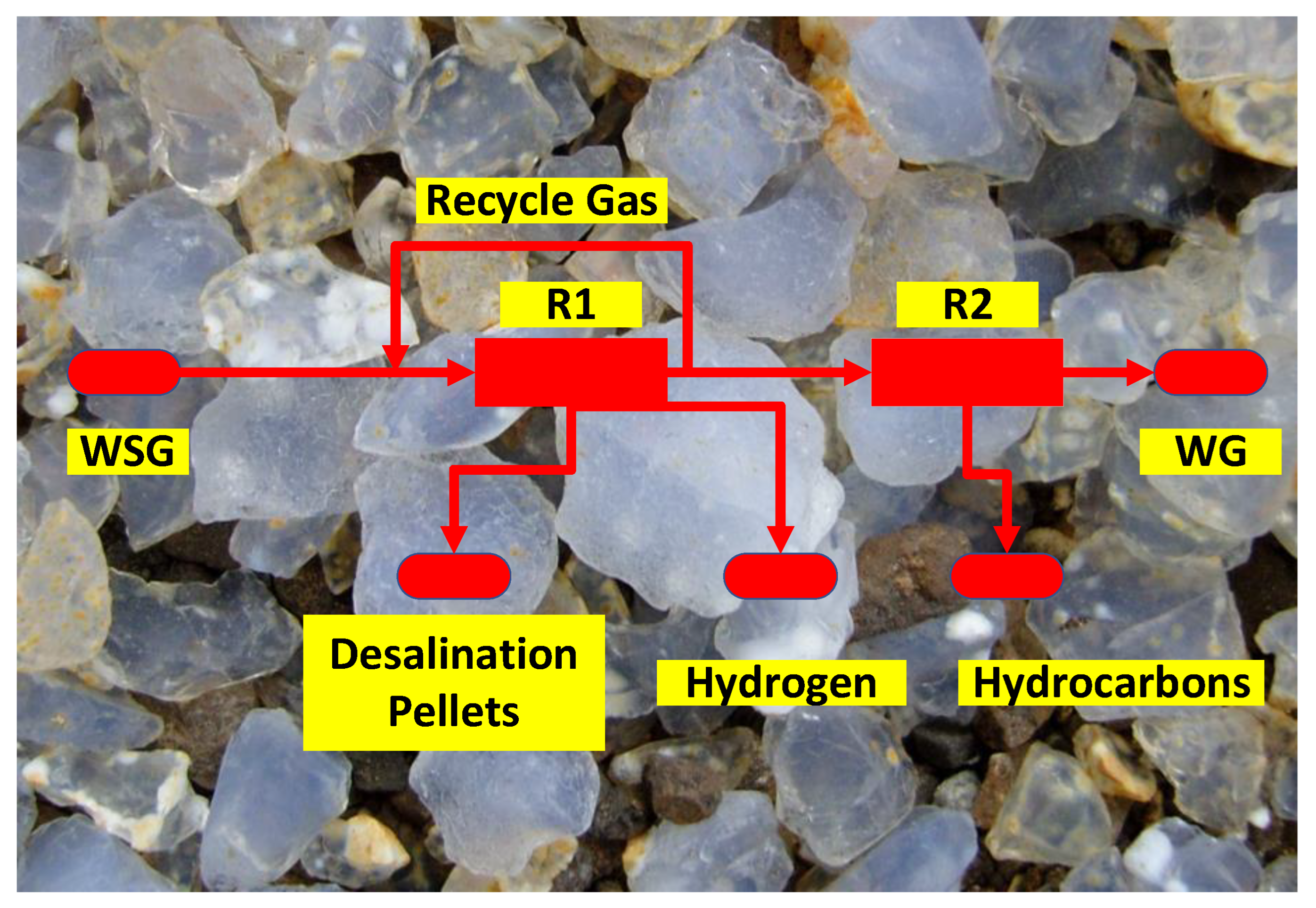
The conceptual commercial design model for a future (TRL7) commercial pilot plant that manufactures desalination pellets (at the onset of this study) is shown in
Figure 5. The concept plant takes a WSG and passes it into a reactor group, termed R1. This reactor group manufactures the desalination pellets and extracts hydrogen. The residual gases are then passed into a second reactor (R2). This reactor uses Fe
0 + CO
2 + H
2O to generate cyclic hydrocarbons. This study examined the operation of the inner shell (
Figure 4) associated with the R1 reactor complex (
Figure 5).
The composition of live WSG is highly variable and is a function of feedstock type, the amount of air used (in an internally heated gasifier), and the moisture content of the feedstock [
56]. The H
2:CO ratio and volume is optimised at a gasifier temperature of 800 to 950 °C [
56].
2.5. Data
The quantitative data is provided in the
Supplementary Materials File in Figures S1–S9. The measured data was collated and processed in accordance with the standard UK statistical methodology [
102]. Regression trend lines and associated statistics were calculated in MS Excel 2019. The coefficient of determination,
R2, is the square of the Pearson Correlation Coefficient (PCC). This coefficient was calculated automatically using Excel 2019, and it is displayed as
R2 using its trendline function. It is used to give an indication of the strength of the statistical correlation between two variables associated with a specific regression trend line [
103,
104]. By definition,
R2 falls between 1 and 0, and PCC falls between +1 and −1 [
103,
104]. A detailed breakdown of the statistical interpretation used between
R2 and the statistical correlation strength is provided in references [
103,
104].
2.6. Patents
The now-lapsed UK patents which apply to the process trains, catalysts, and reactors used in this study are:
- (i)
Maclaurin Retort used to manufacture the WSG from municipal waste: US1130001A; GB191501380A; US1158066A; GB108339A;
- (ii)
Reactor shell structure used to construct the process elements (USA, EPB, and DSA) of the process train: GB2475479B;
- (iii)
Rapid pressure swing adsorption desorption process used: GB2470764B;
- (iv)
- (v)
Construction of the BCDR and the manufacture of desalination pellets and associated catalytic material: GB2520775A.
The reactor train was constructed from three modular units arranged in series. They are a fixed-bed reactor (FBR), a bubble column diffusion reactor (BCDR), and a downstream gas storage volume (DGSV).
In a conventional reactor process, the feed gas pressure and the pressure applied to each part of the FBR and BCDR remains constant at all times. In a RPSAD (rapid pressure swing adsorption desorption) environment, a continual oscillation in pressures is required. This can be achieved by altering the flow pressures entering the reactor complex or by choking the gas flow exiting the process. This applies a simultaneous and constant controlled change through the process.
This study uses a RPSAD process in which (i) increases in pressure (and gas volume) in the FBR are associated with decreases in pressure (and gas volume) in the DGSV, and (ii) decreases in pressure (and gas volume) in the FBR are associated with increases in pressure (and gas volume) in the DGSV.
Linking the three units together creates a single process. Feed gas is supplied at a constant pressure y and flow rate. It creates a continually oscillating pressure within the FBR. The pressure p continually varies within the range of 0.1 MPa and y MPa. The gas volume within the porosity h m3 of the particle bed of the FBR continually varies within the range of h to ((y/0.1)(h)). This part of the reactor process (including associated conduits) is termed an upstream storage area (USA) in GB2475479B.
The BCDR operates as a pressure bridge between the FBR and DGSV. Gas can only flow from the FBR to the DGSV via the BCDR when the gas pressure within the FBR exceeds the restraining pressure. This restraining pressure is exerted by the water column in the BCDR combined with the pressure within the DGSV. GB2475479B terms the DGSV a downstream (gas) storage area (DSA). The BCDR operates within this environment as a poroelastic unit. Its permeability to gas continually varies. This variation is a function of the pressure differential between the pressure in the USA and the pressure in the DSA. GB2475479B terms this unit an elastic permeable barrier (EPB).
The process terminology (USA, EPB, and DSA) is used in the text. The equivalent construction terminology used in the text is FBR, BCDR, and DGSV, respectively. The USA encompasses all of the pipework to the BCDR. The EPB and BCDR occupy the same volume of the reactor. The remaining conduits and volume to the discharge choke point are incorporated in the DSA.
2.7. Reactor Train
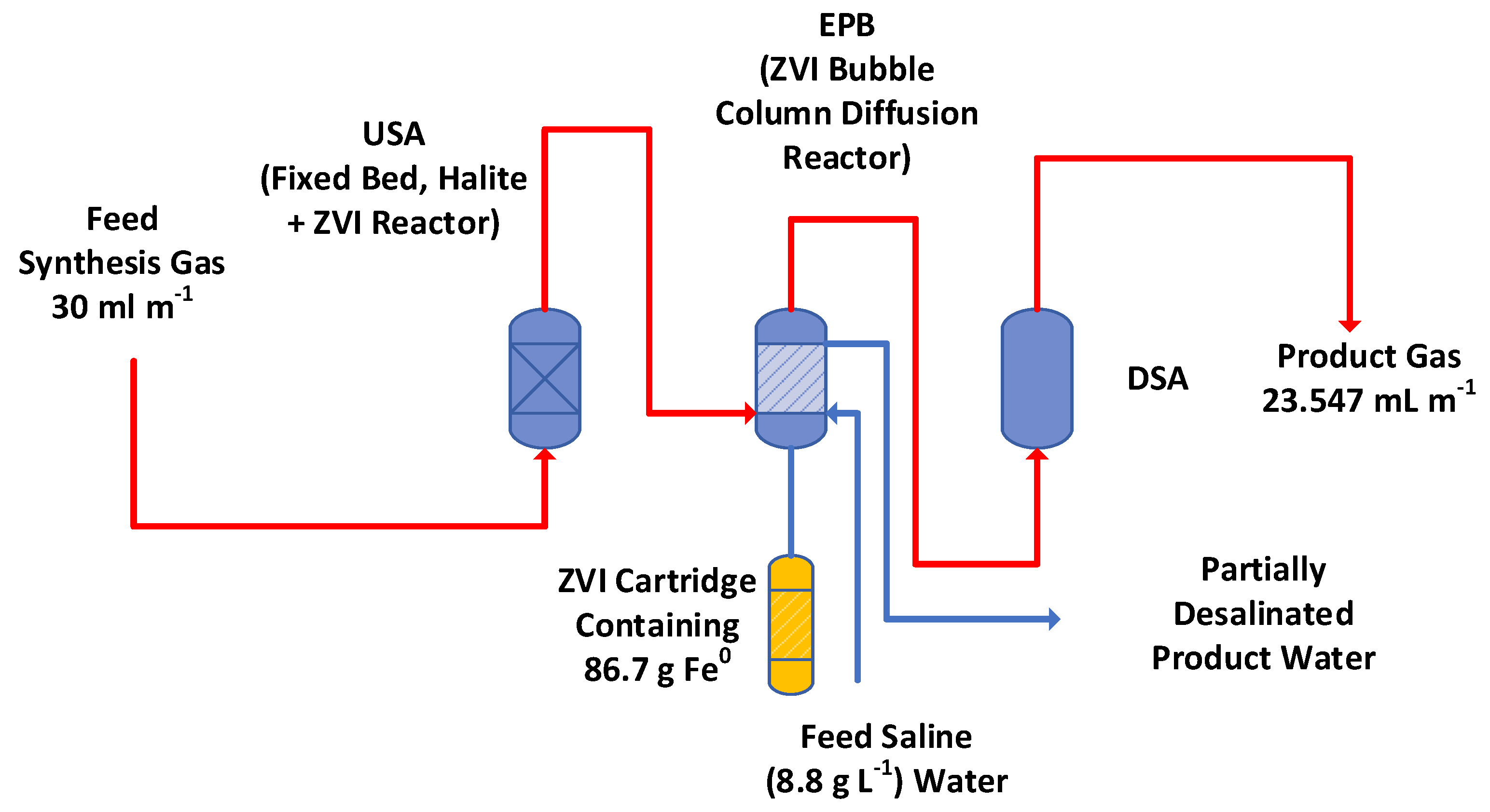
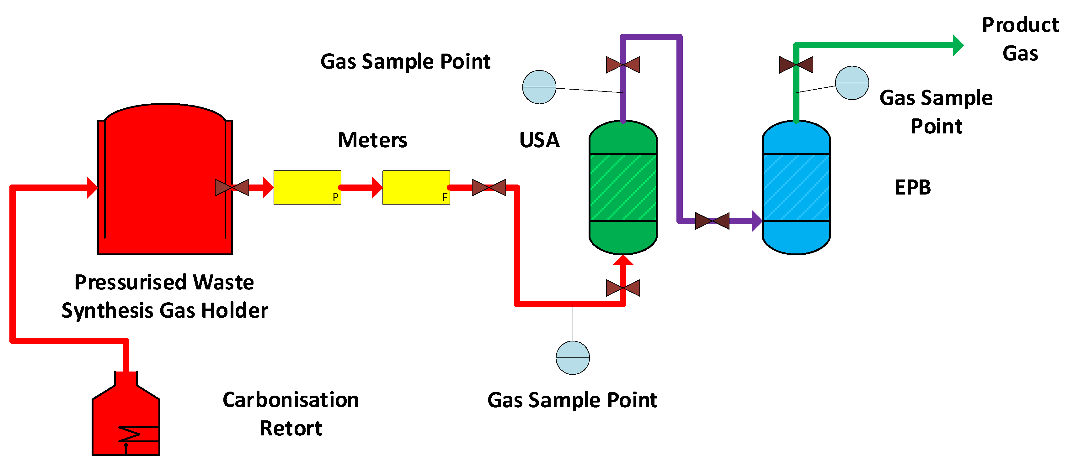
The reactor train (
Figure 6) contains two reactors, a fixed bed reactor (containing halite + m-Fe
0, USA), and a bubble column diffusion reactor containing water, NaCl, and m-Fe
0 (EPB). The USA receives a gas feed. The product gas from the USA is passed to the downstream EPB. The reactor train is operated as a rapid catalytic pressure swing adsorption/desorption reactor (RPSAD). This requires part of the reactor train to operate as an elastic permeable barrier (EPB). It also requires the reactor to contain an upstream gas storage area (USA) and a downstream gas storage area (DSA). The USA, EPB, and DSA terminology, technical requirements, and characteristics are further defined in UK Patent GB2470764B.
RPSAD reactor trains are used to enhance the rate constant for selected reactions by several orders of magnitude. They have previously been used to
A simple mathematical explanation of the assumptions underlying the rate constant increase in a RPSAD reactor train was established [
106]. The RPSAD process enhances adsorption rates during periods of rising pressure and enhances desorption rates during periods of dropping pressure [
106].
2.7.1. SWSG Composition
A dry SWSG was constructed by BOC/Linde, Glasgow, UK (46.03% N
2, 16.88% H
2, 8.33% CO
2, 11.97% CO, and 16.79% CH
4). The gas composition used was based on the gas composition from a Maclaurin internally heated carbonization retort operating at 1200–1500 K (Retort number 4, Grangemouth, UK) [
107].
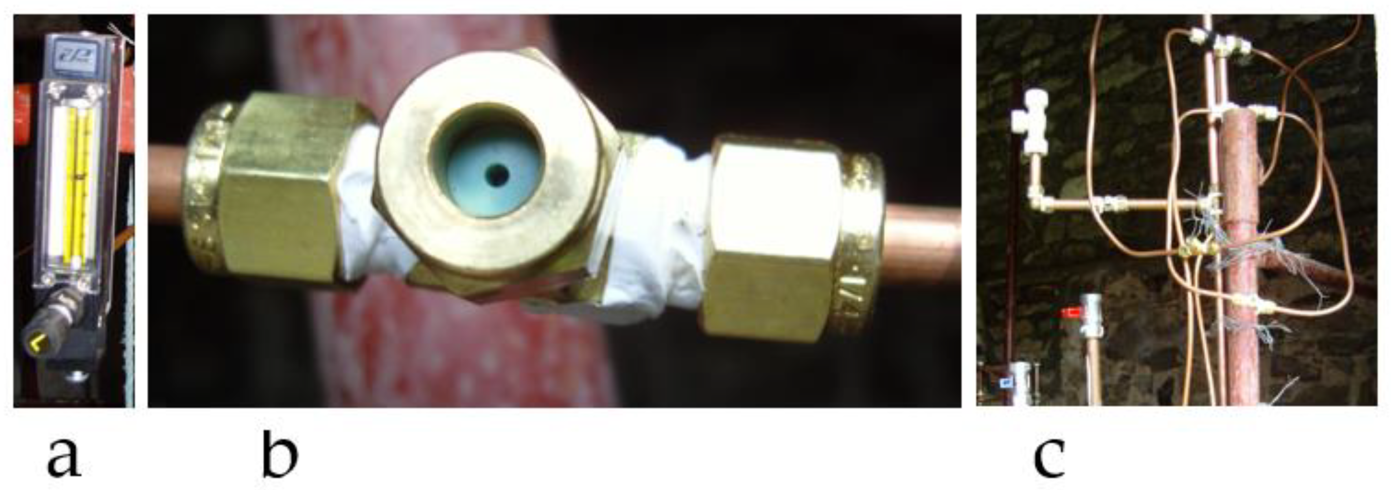
The gas supply pressure was controlled using a pressure regulator supplied (and branded) by BOC/Linde. A second (backup) pressure regulator was placed between the gas supply and the USA. The gas pressure was then checked before entry to the USA using a separate flow line with a heavy-duty gas pressure gauge. This was purchased from Cole Parmer. Separate gas flow lines filled with (liquid) glycerine and equipped with pressure gauges were placed between the USA and EPB and after the EPB. The gas flow rate entering the USA was controlled using an inline, precision-machined, acrylic flow meter. This was configured with a control valve on its inlet, which was purchased from Cole Parmer (
Figure 7a).
2.7.2. Reactor Train Structure
The reactor train was operated continuously at ambient temperatures (283 K to 293 K) for 46.6 days. The feed gas was delivered to the reactor train at a flow rate of 30 mL m−1 and pressure of 0.3 MPa. The trial was terminated when the printed circuit board (PCB) of the gas chromatograph (GC) ceased to operate. The flow rate of 30 mL m−1 was selected to allow direct comparison with the published Route 1 trial.
Gas composition sampling points (such as that shown in
Figure 7b) were placed at three locations (
Figure 8). Their positioning was designed to: (i) monitor the feed gas composition; (ii) monitor the product gas within the USA after it had exited the FBR; (iii) monitor the product gas composition contained within the DSA.
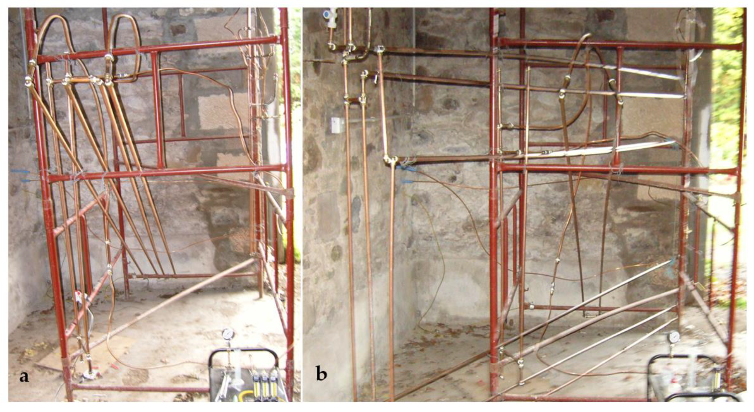
The USA and FBR (
Figure 8) were constructed from 15 mm O.D. Cu
0 conduits. Prior to the commencement of this trial, a number of different FBR lengths and orientations, were trialled. These trials used both 15 mm O.D. and 22 mm O.D. Cu
0 pipework. Orientation of the FBR reactor was found to be unimportant. Inclined or vertical pipework was found to aid the loading and discharge of particulate material into and from the FBR.
The Cu
0 pipes and associate compression fittings were purchased from Screwfix Ltd., Perth, UK.
Figure 9a shows an example reactor containing 12 m of FBR, which was constructed from four inclined, 3 m-long pipe segments. The left-hand pipe segment (
Figure 9a) receives (at its top) the feed gas conduit. The product gas exits the FBR at the top of the right-hand pipe segment. The annuli of the three link segments of pipe connecting the 3 m pipes (
Figure 9a) contain no particulate matter. The FBR section of the USA was constructed (
Figure 9b) from two 3 m-long, 15 mm O.D. (13 mm I.D.) Cu
0 conduits filled with halite + Fe
0 + Cu
0 (
Table 1). The FBR loading was limited by the particle weight, which could be filled into two 3 m-long sections of pipe.
The USA volume incorporates both the porosity within the FBR (
Figure 9) and the annular volume of the link conduits (
Figure 9).
The EPB’s BCDR (
Figure 8 and
Figure 9b) was constructed from 22 mm O.D. Cu
0 conduits arranged to comply with patent GB2520775A. The BCDR had a core rectangular structure. The rising, bubbling gas continually circulates the water within the BCDR in a circular motion around the rectangle. The product gas exits the EPB and enters the DSA. Some of this exiting gas is wet. The DSA structure incorporated a condensation (dew point) mechanism with an associated reflux to recover this water. None of the water was circulated through the ZVI. The water column above the ZVI–water contact contained 2.35 L of water. Gas was discharged from the USA to the EPB, through a 6 mm Cu
0 conduit containing a gas sampling point (
Figure 8). The gas entered the EPB (as 3 mm diameter bubbles through a 3 mm I.D. distributer) at an elevation 10 cm above the ZVI–water contact.
The DSA (
Figure 7c and
Figure 9b) was constructed from 22 mm O.D Cu
0 tubing. The gas conduits were constructed from 4, 6, 10, and 15 mm O.D. Cu
0 conduits. The ZVI (
Table 1) was held in a horizontal cartridge attached to the base of the EPB (
Figure 9b).
The reactor train was constructed using 4 mm, 6 mm, 8 mm, 10 mm, 15 mm, and 22 mm O.D. Cu0 copper tubing and associated brass fittings and valves. These were purchased from Wickes Ltd. Perth, UK; Screwfix Ltd. Perth, UK; Cole Parmer, Saint Neots, UK. Pressure gauges, regulators, flow meters, flow controllers, and valves were purchased from Cole Parmer and BOC/Linde. The copper tubing used was the standard grade used in the UK for household and business gas appliances to convey gas from the gas meter to the gas appliance.
2.8. Gas Measurement and Measurement Equipment
A high-temperature thermal conductivity detector (TCD) and gas chromatograph (GC), both manufactured by SRI Instruments Inc. (Torrance, CA, USA), were used to analyse the gases. The GC was calibrated using standards purchased from BOC/Linde. The calibration levels used were as follows: N
2: 0%, 20%, 46%, 80%; 100%; H
2: 0%, 5%; 16%; 50%; CO: 0%, 1%, 12%; CO
2, 0.1%; 8%, 20%; CH
4: 0%, 10%, 17% 20%; C
xH
y: <10%. A GC area vs. mole % regression curve was used to define the product gas’s concentrations. Samples for GC gas analysis were extracted (from the flow line annulus) using a syringe via a Shimadzu BTO septum (
Figure 7b). The syringe gas sample size was 0.7 cm
3. GC response sensitivity increased with increasing syringe size. A syringe size of 0.5 cm
3 gives an accurate sensitivity to 100 ppm (0.1 mole %). In this study, gas compositional accuracy was assumed to be high for concentrations above 0.1 mole %. At lower concentrations, the results should be interpreted as indicative (indicating presence and relative abundance) with decreasing accuracy as the mole concentration reduces below 0.1 mole %.
The carrier gas was He. The operating conditions were as follows: start temperature: 283 K; ramp temperature: 20 K/min; stable temperature: 523 K; run time: 40 min to obtain molar concentrations of the following: H
2, N
2, CO, CO
2, CH
4, C
2H
x, C
3H
x, C
4H
x, C
5H
x, and C
6H
x. The software used was SRI Peak Simple version 4.88. The use of He as the carrier gas was recommended by SRI. At low concentrations while using an He carrier gas, H
2 gives a positive TCD peak response [
108]. At high concentrations, H
2 gives a negative TCD peak response [
108]. All other gas components give a positive TCD peak response for concentrations between 0% and 100%. To account for these changes, the hydrogen concentration was determined [
2] as:
WSG produced by an internally heated retort contains N
2 [
107]. The N
2 in the feed gas acts as an inert gas [2.3]. A flow meter (
Figure 7a) was used to measure the gas flow rate entering the reactor complex. It automatically follows that the product gas flow rate will be directly proportional to the concentration of nitrogen contained in the product gas. Most flow meters have rate gauges, which are a function of the gas composition being processed. Therefore, the only accurate values for the product gas flow rates are obtained by normalising the gas composition in the product gas. Normalisation is relative to the gas composition in the feed gas. This approach has been an accepted practice in FT studies since the 1930s [
109].
The number of moles of N
2 entering the reaction environment equals the number of moles of N
2 leaving the reaction environment [
2,
3]. This allows the normalised gas species
Gs’s concentration in the product gas (
Supplementary Materials Figures S1–S6) relative to the feed gas
CN to be determined [
2,
3] as:
where
CA = observed molar concentration of G
s in the product gas,
Nf = molar concentration of N
2 in the feed gas, and
Np = molar concentration of N
2 in the product gas.
2.9. Chemicals
The halite granules (0.5–5 mm) were purchased from Wickes Ltd., Perth, UK. The zero-valent metals (m-Fe0, m-Al0, m-Cu0), were purchased from MB Fiberglass, Newtownabbey, UK. The powders had a particle size within the range of 0.002 to 0.08 mm.
The exact particle size, composition, and concentrations of the feed’s Fe0, Cu0, and Al0 were not considered to be critical. The Fe0 powder’s characteristics are as follows. Particle Data: <45 Microns = 70%; Apparent Density: Approx 2.8 g/cm³; Chemical Analysis: Fe—Total: 93%; Fe—Metallic: 87%. Cu0 powder passes through a 240 mesh; 95% of Al0 particles are <350 microns.
The fresh water used in the experiments was natural spring water (pH 6.5) emanating from fractured andesites belonging to the Devonian Old Red Sandstone Volcanic Series (Source National Grid Reference: NO 02,817 14399; 56°18′43″ N, 003°34′21″ W).
2.10. Water Analysis Measurement Equipment
The instruments used were:
ORP (oxidation reduction potential) meter (HM Digital) calibrated at ORP = 200 mV; measured ORP (oxidation reduction potential) values were converted to Eh, mV as Eh, mV = −65.667pH + 744.67 + ORP (mV) using a quinhydrone calibration at pH = 4 and pH = 7.
pH meter (HM Digital) calibrated to pH = 4.01; 7.0; 10.0.
EC (electrical conductivity) meter (HM Digital meter calibrated at EC = 1.431 mScm−1).
Cl− ISE (Ion Selective Electrode); Bante Cl− ISE, EDT Flow Plus Combination Cl− ISE; Cole Parmer Cl− ISE attached to a Bante 931 Ion meter. Calibration was undertaken using 0.001, 0.01, 0.1, and 1.0 M NaCl calibration solutions.
Na+ ISE (Ion Selective Electrode); Bante Na ISE, Sciquip Na ISE; Cole Parmer Na ISE attached to a Bante 931 Ion Meter. Calibration was undertaken using 0.001, 0.01, 0.1, and 1.0 M NaCl calibration solutions.
Temperature measurements were made using a temperature probe attached to a Bante 931 Ion Meter.
2.11. Pellet Formation
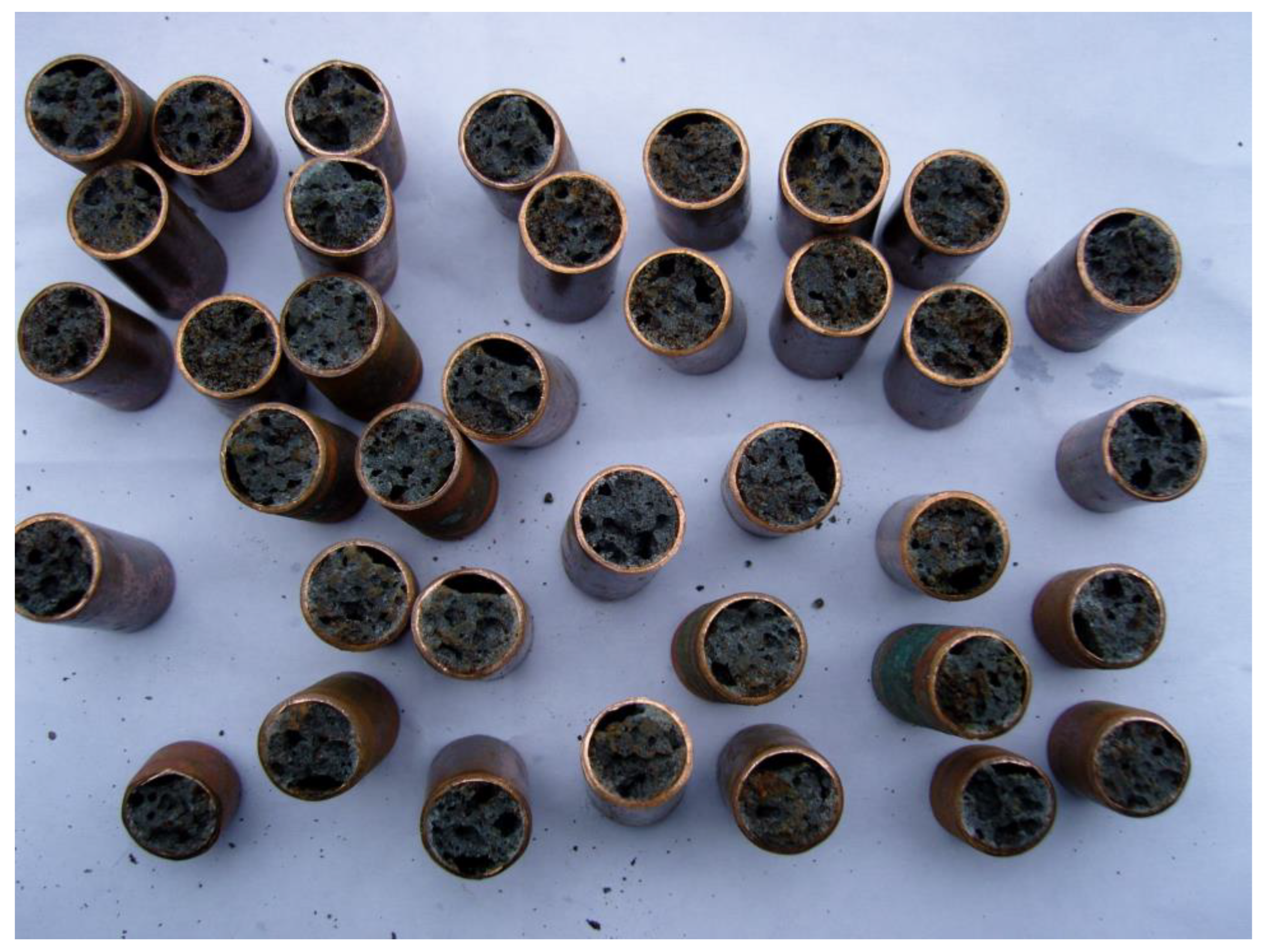
At the conclusion of the trial, the ZVI cartridge was removed from the reactor. A Rothenberger pipe slicer was then used to cut the 15 mm O.D. pipe. This was achieved without the cutting wheel penetrating the Fe
0:Fe(a,b,c)@C
0 polymer. At this point, the polymer was brittle, and a twist of the pipe resulted in a clean flat break (
Figure 10). The pipe was cut into 15 mm- to 25 mm-long segments. Each segment was measured and weighed. This allowed the weight of polymer and the weight of the Cu
0 associated with each pellet to be determined.
There is no specific significance to the pellet length selected. Prior unpublished work indicated that 10 mm- to 30 mm-long pellets had a higher desalination rate constant than 10 cm- to 30 cm-long pellets. The Rothenberger pipe slicer allows pellets to be cut such that a 20 mm target pellet has a length of between 18 and 22 mm.
2.12. Hydrogen Losses
The GC results indicate a significant loss of hydrogen. The simplest explanation is that this hydrogen was adsorbed by the material contained within the EPB and USA. Alternatively, it was lost via discharge through the copper conduits, or it was removed by the CxHyOz species contained in the water.
A sample of the product water from the EPB was sent to Hall Analytical Laboratories Ltd. (part of the Agilant group), Manchester, UK for GCMS analysis. GC-MS analyses were performed using an Agilent 5973 mass spectrometer linked to an Agilent 6890 gas chromatography system. The organic components in the water were extracted, using dichloromethane (DCM). The analysis indicated traces of cyclohexane–isocyanatno; cyclohexane–isothiocyanatno; Phenol,2,5-bis(1,1-dimethylethyl); two unidentified species.
This analysis does not indicate that any significant C
xH
yO
z species formation occurred in the BCDR during the reaction period. This observation is consistent with aqueous FT observations when a carbon source is supplied in the water [
90,
91]. It is not consistent with aqueous FT when the sole carbon source is iron carbides contained within the Fe
0 particles [
92,
93,
94].
The disappearance of the hydrogen is unresolved. The extensive presence of Cu(OH) and Cu(OH)
2 on conduits associated with the disappearance of H
2 (
Figure 11) is enigmatic. These precipitates are interpreted here as probably indicative of hydrogen leakage through the Cu
0 pipes.
2.13. Carbon Switching Trial
The bulk of the pellet formation cost is associated with cost of Fe0, the cost of Cu0, and the long time frame taken to produce a product. The evaluation of the results indicated that the presence of Cu0 may not be essential. Similarly, a major function of the Fe0:Fe(a,b,c) polymer appears to be to produce dead-end porosity to hold the removed NaCl. Therefore, it may be possible to remove the requirement for Cu0 and the bulk of the Fe0:Fe(a,b,c) polymer by switching to a porous active carbon source as the primary support to create porous C0:Fe(a,b,c) pellets.
No specific n-Fe0 precipitation method is preferred in making the C0@Fe0 desalination catalyst. The normal precipitation approach is to use a sol-gel approach, whereby an Fe salt is dissolved in water (the exact molar concentration is not critical). In this study, the concentration used was 100 g FeSO4 L−1. An appropriate amount of activated carbon (preformed moulded porous pellets (5 mm × 10 mm cylindrical pellets)) was added to the water containing the FeSO4. The mixture was allowed to soak for 24 h at NTP. The weight ratio of carbon to Fe used was 99.6%C0 + 0.4%n-Fe0. A reductant was then added to precipitate the n-Fe0 onto the C0 support.
The Fe
0 precipitation agents which can be used include: NaBH
4 (KR100975822B1; US20070022839A1), KBH
4 (US20070022839A1), LiBH
4 (US20070022839A1), Na
2S
2O
4 (US8283034B2), Li
2S
2O
4 (US8283034B2), K
2S
2O
4 (US8283034B2), MgS
2O
4 (US8283034B2), CaS
2O
4 (US8283034B2), N
2H
4 [
110], and polyphenols (US7963720B2; CN106077624B; CN112755963A; CN109967024B; CN113477214A). Polyphenols include, but are not limited to, tea extract, green tea extract, coffee extract, lemon balm extract, sorghum bran, sorghum bran extract, polyphenolic flavonoid, flavonoid, flavonol, flavone, flavanone, isoflavone, flavans, flavanol, anthocyanins, proanthocyanins, carotenoids, catechins, quercetin, and rutin (CA2728987C).
The choice of reductant is not critical. Likewise, the amount of reductant required is not critical, provided it is in excess of the minimum required to convert all the Fe
2+ ions to Fe
0. The C
0@Fe
0 desalination catalyst used in this study was created using a gallic acid polyphenol concentrate derived from black tea. The C
0@Fe
0 desalination catalyst was removed from the sol-gel solution after 4 h at NTP. The Fe
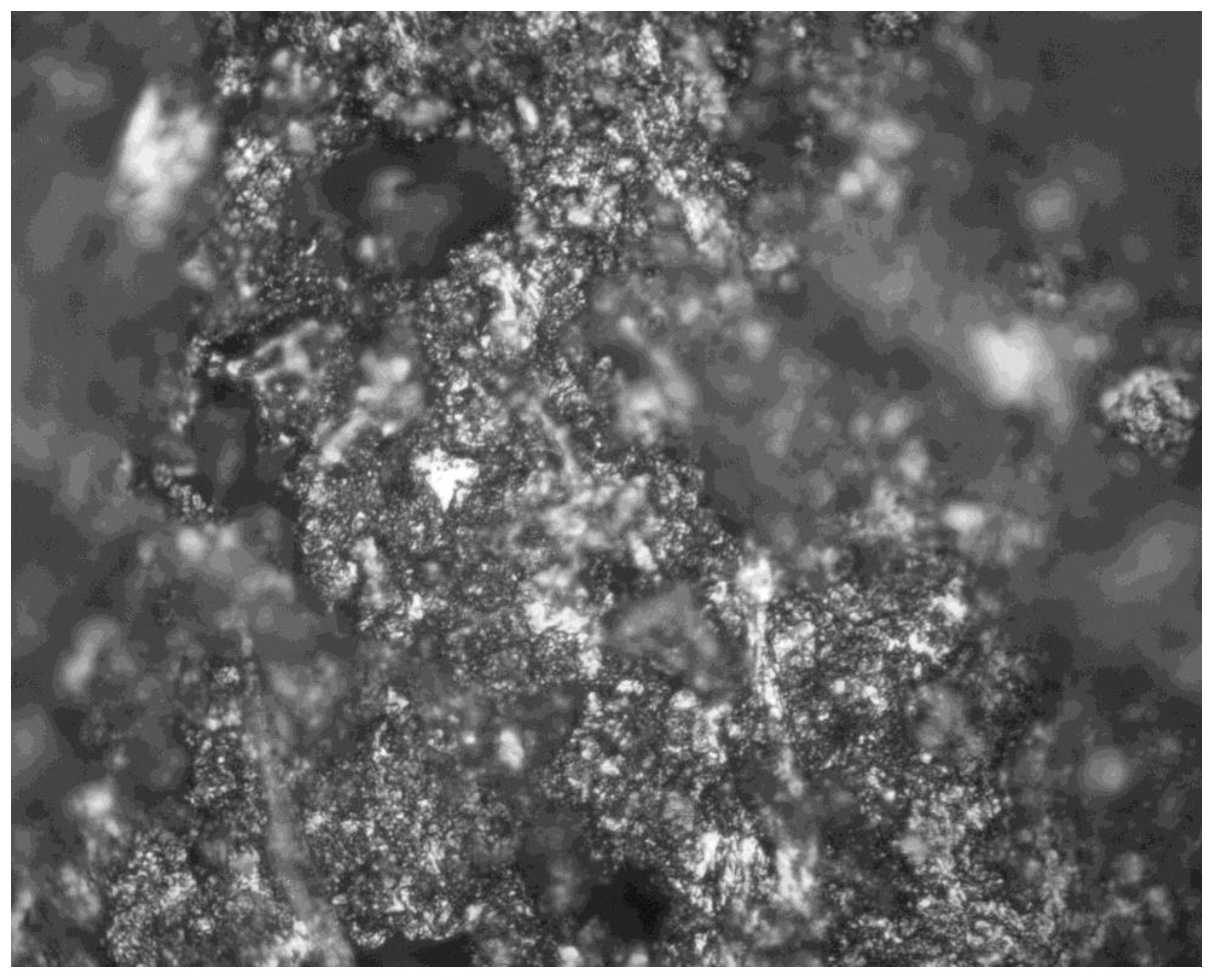
0 produced using this process also incorporated some Fe-organic (Fe(b,c)) precipitates. The resultant pellet structure is illustrated in
Figure 12.
2.14. Desalination Trials
The desalination trials were operated as follows:
2.14.1. Fe0:Fe(a,b,c)@C0 Trial
The 15 mm O.D Cu
0 sheathed ZVI cartridge was removed from the reactor train after 46.6 days and drained. The cartridge was then cut into 15 to 25 mm segments, where each segment is defined here as a pellet (
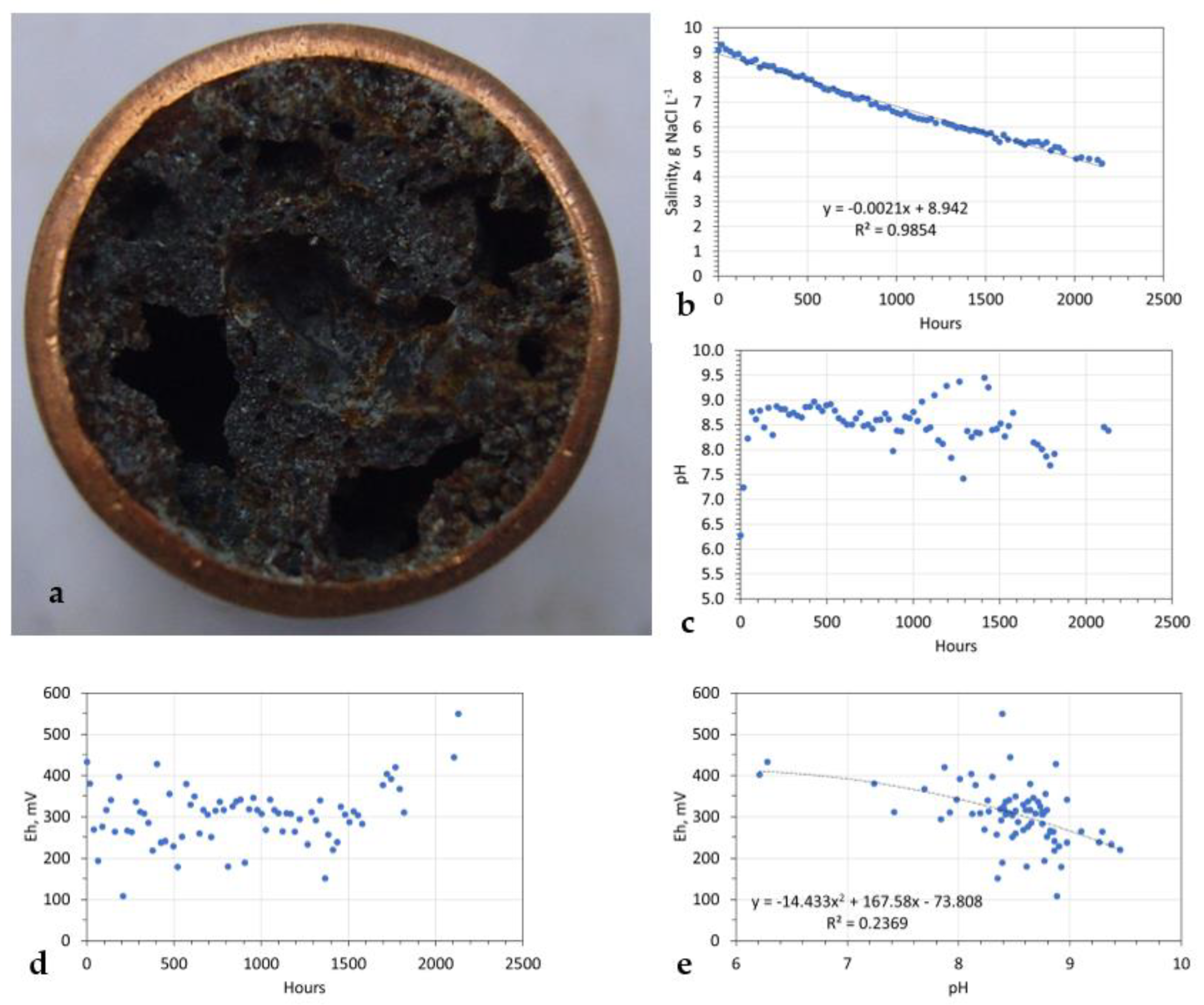
Figure 10). A typical cross-section through a pellet is shown in
Figure 13a. Each pellet is highly porous and contains both interconnected and isolated pores and vugs. The total weight of pellet material recovered, excluding the weight of the Cu
0 shell, was 240 g.
The pellets were intended for use as desalination pellets. An example of operation is provided in
Figure 13b. In this example, 44.65 g of pellets were added to 1 L of static saline water (9.2 g NaCl L
−1; Eh = 401.88 mV; pH = 6.21; EC = 15.2 dSm
−1; temperature = 280 K). The pellets contained the following: 25.34 g Fe:Fe(b)@Cu@Al@Ca@C
0 polymer + 19.31 g Cu
0 pellet shell.
The sealed reactor had a head space (air) of 1.3 L. The reactor shell and top seal shielded the water from UV light. The reactor was placed in an unheated, partially open steading building. It was exposed to natural fluctuations in atmospheric temperature and pressure during the trial period.
2.14.2. C0@Fe0:Fe(a,b,c) Trial
The sealed reactor contained 1 L of static water and had a head space (air) of 1.3 L. The reactor shell and top seal shielded the water from UV light. The reactor was placed in an unheated, partially open steading building. It was exposed to natural fluctuations in atmospheric temperature and pressure during the trial period. n-Fe0 in the amount of 0.2 g L−1 precipitated onto and into the active carbon; the active carbon totalled 50 g L−1; the pellet size was 10 mm × 5 mm. The feed water salinity was 30.74 g L−1.
2.15. USA:FBR Control Experiment
Hydrocarbon formation was recorded when the FBR only contained NaCl + silica gel (Route 1) and when the FBR contained NaCl + Fe
0 + silica gel (Route 2). A control FBR (constructed from 15 mm O.D Cu
0 tubing) was filled with 130 g m-Fe
0 + 130 g silica gel particles (to provide permeability). The synthetic WSG passed through the FBR at a rate of 30 mL m
−1 for a period of 8 h. The gas delivery pressure was 0.3 MPa. The reactor was operated at ambient temperature (278 K to 285 K). The product gas was analysed for C
xH
y where x = >1. No hydrocarbon formation was observed. The results of this control test imply that NaCl can facilitate the production of hydrocarbons from WSG at ambient temperatures. A possible reaction sequence for the production of hydrocarbons in the presence of NaCl is documented in
Table 2.
3. Gas Flow Results
The total volume of feed gas processed was 2.031 m3. Of this volume, 0.96264 m3 was N2; 1.086 m3 was potentially removable. Approximately 240 g of desalination catalyst was manufactured in the process. The average product gas flow rate leaving the FBR was 19.935 mL m−1, indicating an average volume contraction of 34%. The average product gas composition was 69.41% N2 + 1.21% H2 + 9.09% CO2 + 9.2% CO + 11.1% CH4 + 0.2% CxHy.
The average product gas composition, normalised to the feed gas, was: 46.03% N
2, 0.80% H
2, 6.03% CO
2, 6.10% CO, 7.36% CH
4, and 0.13% C
2+. Total product gas volume was 1.337 m
3; the variation in the product gas’s composition is summarised in
Table 2.
A characteristic of all RPSAD process operations is high variability in product gas composition. This is demonstrated in
Table 3, and it reflects the impact of oscillating pressure on adsorption and desorption rates. In an RPSAD process, the most accurate impression of the process is given by the average product composition.
The trial established statistical positive correlations between CH
4:CO, CO:CO
2, CO
2:CH
4, CO
2:H
2, and CH
4:H
2 (
Supplementary Materials, Figures S1–S3). CH
4 and H
2 concentrations were always less than in the feed gas composition. Both CO and CO
2 compositions’ concentrations can be above their levels in the feed gas. This is interpreted as an indication that (i) CH
4, CO, and CO
2 are adsorbed to form C
0 + H
2O; (ii) the pulsed desorption of CO, CO
2, or localised reversal of the CO
x removal reaction can occur.
The net adsorption reaction was:
Of the feed carbon volume, 47.4% was converted to C0 or CxHy; x = >1. The observed selectivity for the removed carbon atom destination was 96% C0 + 4% CxHy.
The average product gas composition, normalised to the feed gas entering the FBR, was 46.03% N
2, 1.50% H
2, 9.29% CO
2, 9.92% CO, 11.59% CH
4, and 0.16% C
2+. The variability associated with the RPSAD process is demonstrated by the highly variable outcome ranges in
Table 4. The total product gas volume was 1.581 m
3. The increase in product gas volume relative to gas feed from the FBR was 0.2438 m
3. Positive correlations were present between CH
4:CO, CO:CO
2, CO
2:CH
4, CO
2:H
2, and CH
4:H
2 (
Supplementary Materials, Figures S4–S6). The observed C
2+ compositional statistics are provided in
Table 5.
The following average stoichiometric changes to the gas received from the FBR occurred:
The observed generated gas composition was 0.2%C2H2 + 35.1% CH4 + 27.1% CO2 + 31.7% CO + 5.8%H2. This analysis indicates that the bulk (64.6%) of the 17.6 moles of C0 removed in the FBR was entrained in the gas entering the BCDR. A maximum of 0.674 moles (8 g) of n-C0 (over the 46.6-day reaction period) was retained in the FBR, removed in the BCDR (to form the Fe0:Fe(b)@C0 desalination catalyst), or was contained in the product gas leaving the BCDR.
4. Desalination Pellet Results
The results of a single typical example trial test are reported here to illustrate the principal features associated with desalination. The pellets (
Figure 13a) were placed in a static water body and monitored for 2152 h (89.6 days). The temperature was allowed to vary with changes in ambient temperature within the range of 273 to 283 K. The results indicated:
There is a weak negative polynomial regression relationship between Eh and pH (
Figure 13e). This experiment confirms that the Route 2 process can be used to manufacture desalination pellets. These pellets have similar operating characteristics to those manufactured in Route 1.
The placement of Fe
0 or Fe
0:Fe(a,b,c) into a static body of water always rapidly increases the pH of the water. This change results from a primary reaction, which is catalysed by Fe
0. This reaction is 2H
2O = 2OH
− + 2H
+. This reaction initially rapidly increases pH to a new stable level (
Figure 13c). The pH then stabilizes, or drifts downwards, as additional OH
- ions are removed by the Fe via the reaction Fe
0 + 3OH
− = Fe(OH)
3 + 3e
− (
Figure 13c).
The increase in H
+ ion availability coupled with the increased availability of e
− and the stable Eh at the water-Fe boundary results in the reactions H
+ + e
− = H (physically adsorbed) and 2H
+ + 2e
− = H
2. Both of these reactions are associated with the initial decrease in Eh (
Figure 13d). The substantial rise in Eh after 1500 h (
Figure 13d) is associated with the change in Fe composition from Fe(OH)
x to FeOOH; i.e., Fe(OH)
3 = FeOOH + H
2O; Fe(OH)
2 = FeOOH + H
+ + e
−. This reaction suite occurs at a higher Eh than the initial reaction set [
1].
There is always a negative relationship between Eh and pH in a redox environment (
Figure 13e) [
1] due to the pH reaction H
2 = 2H
+ + 2e
−, where Eh = −0.0591 pH. Superimposed on this trend are the Eh:pH mineralogical (ion) reactions in water at the appropriate Eh and pH. In a redox environment, the equilibrium constant for each of these reactions is pH-dependent. The Eh changes (and variation) at a specific pH, result from the reaction quotients of the simultaneous reactions striving to reach equilibrium. The relationship between Eh and pH is defined by the Nernst Equation [
1].
A statistical analysis of the performance of Route 2 desalination pellets is provided in
Table 6. For comparison, a similar table is provided for Route 1 desalination pellets (
Table 7). Both routes provide similar levels of desalination.
7. Conclusions
This study establishes the following: (i) a FBR containing a mixture of Fe0 and NaCl can be used to covert CO, CO2, and CH4 to n-C0; (ii) passage of the n-C0 into a BCDR containing Fe0 results in the formation of the desalination catalyst (Fe0:Fe(a,b,c)@C0) + CH4 + CO + CO2 + CxHy, where x > 1. This process is interpreted as belonging to the Fischer–Tropsch group of processes. Of the total volume of CH4 + CO + CO2 entering the FBR, 47.4% was converted to C0+ CxHy, where x >1. The selectivity was 96% n-C0 + 4% CxHy. The BCDR converted 64.6% of the n-C0 into CH4, CO, CO2, and CxHy. The selectivity was 37.2% CH4 + 28.7% CO2 + 33.6% CO + 0.5% CxHy. The residual n-C0 (35.4%) was retained in the n-Fe:Fe(a,b,c)@C0 polymer.
The desalination catalyst, when placed in water, reduced its salinity using a pseudo-zero order reaction. An analysis of pellet performance indicates that an average of >60% desalination is achievable. The removed NaCl was sequestered with the dead-end porosity of the catalyst. A single feasibility experiment tested the hypothesis that the critical location for the catalyst is on the surface of a pellet containing dead-end pores. This experiment (using C0@Fe0:Fe(a,b,c) using a seawater feedstock established a pseudo-second order desalination profile. It achieved >85% desalination.
