1. Introduction
In the water and waste removal industries, it is important to be able to measure the amount of fluid accurately. Use of a flow meter can be problematic, due to the turbulence and irregular flow that exists within the pipe network. Even a small percentage error in a pumping station can lead to significant differences over a year. To overcome this problem, a flow conditioner can be added to the system to reduce the flow disturbances that occur from lack of straight piping or poor layouts. With flow conditioners, the turbulence within the pipe will be dramatically reduced by homogenizing the velocity profile and removing the swirl. This will allow the flow meter to take a more accurate reading.
Whenever there is a change in the direction of a pipe or a disturbance in the system, it has an impact on the velocity profile and thus the flow measurement taken by the flow meter. A fully developed velocity profile can only be achieved in straight piping, so in other situations flow conditioners are required to achieve accurate and repeatable measurements [
1]. Flow conditioners not only redistribute the velocity profile but will also reduce or even remove any swirl, with swirl-free flow being defined as the swirl angle,
where
and
are the tangential and axial velocity components, respectively, being below 2° [
2]. The advantages of a fully developed velocity profile come at the expense of an additional drop in pressure across the conditioner [
3]. The geometry of the conditioner plate is critical in determining its performance, as well as the pressure loss across the plate.
Xiong et al. [
4] carried out an experimental study to investigate the effects of velocity and turbulence measurements downstream of three different flow conditioners. The three flow conditioners were a tube bundle with the length 2.54D and two perforated plates: Akashi et al. [
5] and Laws [
6]. Two set-ups were considered at a Reynolds number of 10
5: a 90° bend with a bend radius of 2D; and two 90° out-of-plane bends. The flow conditioner was placed 2D downstream of the bend(s) and velocity profiles were presented in the near-field, where the jets, passing through the conditioner, could be distinguished for x < 4D, as well as the far field. Swirl was found to be significantly reduced, compared to when no conditioner was present, and for all three configurations the swirl angle was found to be around 1° for x/D > 1.5. They concluded that the flow profile matched a fully developed flow at approximately 25D downstream, and that the perforated plates have a higher efficiency than the tube bundle.
Benhadj and Ouazzane [
7] considered a vaned plate and an NEL plate flow conditioner. The vaned plate [
8] had six vanes attached on the upstream side of a 70% porous plate with a central hole of 0.224D and two circles of holes, of radii 0.213D and 0.117D, coming out from the center. The NEL plate flow conditioner had 47.5% precocity and consisted of three circles of holes. The inner circle had 4 holes with the smallest diameter of 0.1D, the second circle had 8 holes with the largest radius of 0.16D and the outer circle had 16 holes of radius 0.12D. The plates were placed 3D downstream of a ball valve which generated asymmetric swirling velocity profiles. The experiments were run for 0.3 × 10
5 < Re < 1.6 × 10
5 for different flow conditions generated by different valve openings. They considered velocity profiles, pressure drops and the effect on the coefficient of discharge on an orifice plate meter downstream of the conditioner. Both conditioners were found to be good for removing swirl, with the NEL plate performing slightly better. However, the vaned plate showed a head loss of less than 1/3 of that of the NEL plate, and performed well for all upstream conditions considered. Although the NEL plate was good at removing swirl, it was poor at recovering a fully developed flow.
Ouazzane and Benhadj [
9] performed an experimental study using a number of conditioners, from which they proposed a new flow conditioner consisting of a graded Laws perforated plate with upstream vanes and short downstream tabs. This was shown to work in two stages, with the vanes acting to remove the swirl and the perforated plate reconditioning the flow to a fully developed profile within 6D.
Drainy et al. [
10] performed a CFD investigation of a Zanker plate [
11] which was designed with five holes, sized such that the smaller holes are concentrated near the edge of the plate, to try to reduce the major concentration of eddies and swirls that occur near the wall. A radial reduction in the hole diameters is also used to assist with stabilizing the velocity distribution. The simulations showed that the velocity profile becomes consistent at distances exceeding 5D downstream from the conditioner, with relatively few fluctuations in the profile. The fully developed axial velocity profile was found to have an acceptable qualitative agreement with comparable profiles discussed in [
4,
12,
13]. The swirl angle was found to depend on the thickness of the plate and was less than 2° for plate thicknesses greater than 2 mm; however, increasing the thickness caused the pressure to increase.
Chen and Liu [
14] used CFD to investigated an Etoile flow conditioner of length 2D, consisting of 8 Etoile straighteners, or vanes, emanating radially from the center of the pipe, installed 5D downstream from the vortex generator at Re of 5.84
and 5.84
. They concluded that the vanes at the center (r/D < 0.1) acted to obstruct the fluid, but that for r/D > 0.3, they were too sparse. They therefore proposed a refinement whereby the straighteners were removed in the center (r/D < 0.1) and an octagonal star was added to the cross-section consisting of two square at 45° to each other, which were extruded through the full 2D of the conditioner. They concluded that their modification gave better performance up to 20D downstream, but suggested that practical application should be tested in the future.
Yin et al. [
15] considered a flow conditioner, consisting of a bundle of 19 tubes placed behind an out-of-plane double 90° bend, by performing RANS (Reynolds Averaged Navier–Stokes) simulations using the
k-ω turbulent model. They presented results at Re = 1.0
and found that the flow conditioner significantly reduced the tangential velocity between 3D and 30D downstream, effectively removing the helical flow structures which were observed without the conditioner. In terms of the axial velocity, the result initially showed strong jet-like flows close to the flow conditioner (3D down-stream), which decayed by a distance of 5D. From a distance of 20D down-stream, the axial velocity profile is in good agreement with the profile for a straight pipe when the flow conditioner is present, compared to the case with no flow conditioner, where deviations due to the helical flow are observed up to 30D downstream. At all distances down-stream which were considered, the axial velocity profile maintained the standard features of turbulent flow with a large velocity gradient close to the wall and a gentle profile across the central region of the pipe (with the addition of jet-like motion close to the flow conditioner).
In terms of practical industrial applications Kiss and Patziger [
16] considered flow measurement in municipal wastewater treatment reactors and identified a range of difficulties in obtaining accurate and repeatable measurements. Challenges in monitoring and measuring wastewater flow were also identified by Dawoud et al. [
17], who considered flow measurement in municipal wastewater systems. They proposed a design for a venturi meter to measure flow and tested it in a hydraulic flume. Comparisons between measured and actual flow were presented and the differences combined into a discharge coefficient, which varied between 1.00 and 0.81, indicating a level of variation in the measurements. No consideration of the turbulent nature of the flow was taken. The issue of flow-conditioner blockage due to sand transport was considered in the application of shale gas extraction by Peng et al. [
18,
19]. In [
18], both an experimental and a CFD approach were applied for a Zanker plate. In the experimental apparatus, a funnel was used to insert sand into the air flow in a straight section of pipe containing the Zanker plate. Simulations were performed using a RANS approach with a
k-ε turbulence model, where regularly sized sand particles were introduced at a constant mass flow rate. The results showed that, for a velocity between 3 and 8 ms
−1, a blockage easily formed in the conditioner, and this was also found to be a long-term effect. The blockage was found to have an effect on the accuracy of flow measurement downstream from the flow conditioner. In [
19], this effect was further analyzed using a novel flow conditioner with regularly sized holes. Here, the experimental and simulation data was found to be in good agreement, and the effect of particle size and Reynolds number was studied. Investigations into the accuracy of ultrasonic flow meters for natural gas were performed by Liu et al. [
20] and Peng et al. [
21], both using a RANS
k-ε simulation approach. In both cases, deviations of the flow were observed, although the specific details of the flow conditioner geometry were not apparent.
Flow conditioners have found applications in many industrial areas where it is important to be able to obtain accurate measurements of the volume flow rate through the system and also where space is limited. As well as waste water systems [
16,
17], they have been applied to higher value products, such as in the oil [
22] and gas [
19] industry, and in the petrochemical industry [
15], where it is important to control the flow rate to chemical reactions. The concept of flow conditioning had also been seen to be important in a range of diverse areas, such as the reduction in noise [
23] in an air-conditioning unit.
In this paper, a new conditioner design will be presented, with its design based on the performance of the existing conditioners considered in the literature. CFD simulations will then be presented for the new design in a pipe system with two 90° bends at a Reynolds number of Re = 6.09 .
3. Results
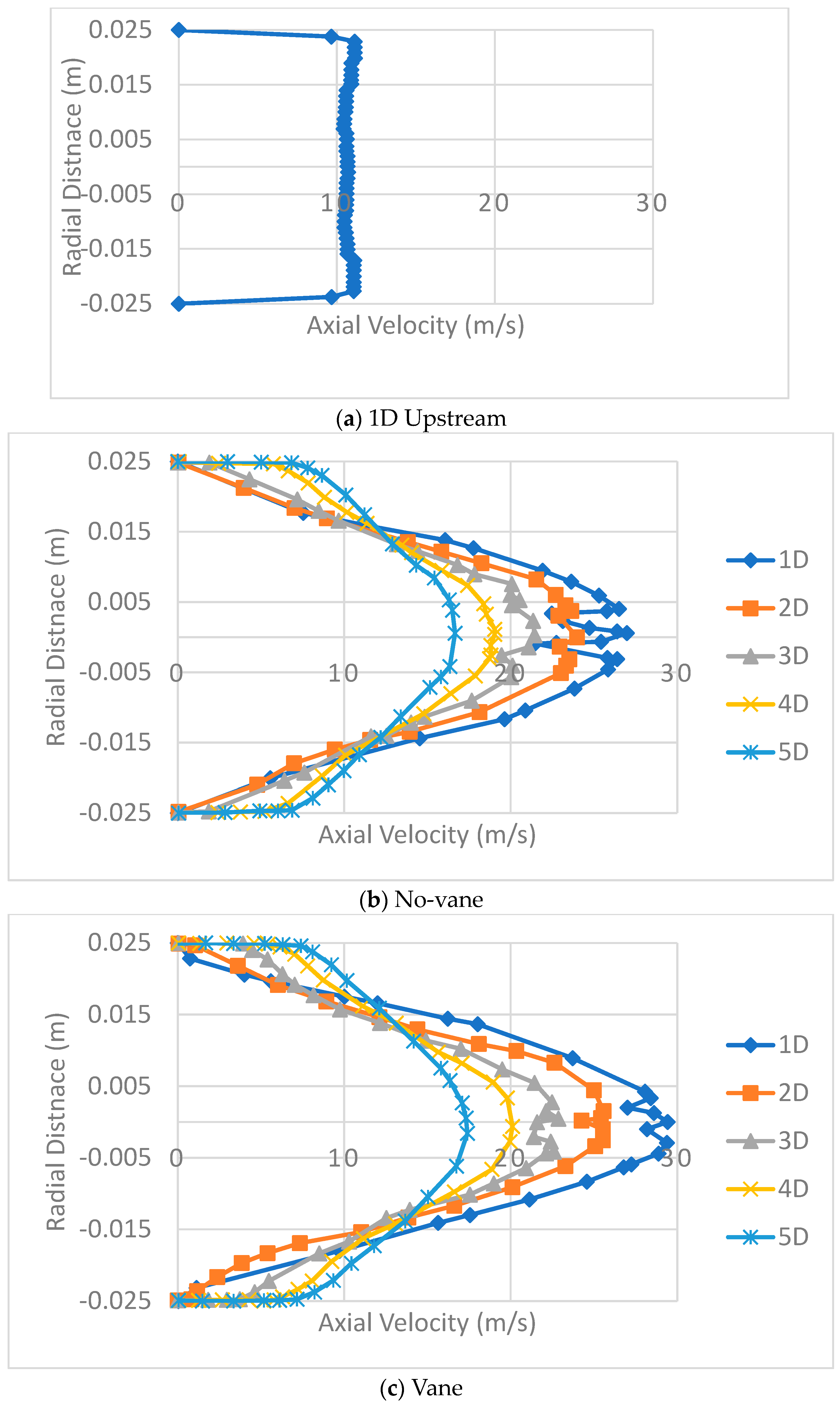
The axial velocity profiles are shown in
Figure 6.
Figure 6a shows the profile 1D upstream from the conditioner and
Figure 6b,c show the profiles for the no-vane and vaned cases, respectively, at distances 1D, 2D, 3D, 4D and 5D downstream. We consider first the design without a vane. The axial velocity profile at one diameter downstream of the conditioner, compared to the turbulent profile before the conditioner, is more parabolic, with a reduced velocity gradient near the wall and an increased axial velocity and maximum velocity in the central region of the pipe. 1D down-stream of the flow conditioner, the axial flow profile is more parabolic in nature than was found at higher multiples of the diameter; however, fluctuations are observed in the central region, indicating that the flow profile is not ideal. At 2D down-stream, the result shows that there is still some variation in the central region, but it is significantly reduced compared to the 1D result, while still maintaining a relatively parabolic flow profile. This suggests that the optimal position to place a flow meter would be between 1D and 2D down-stream of the flow.
Between 3D and 5D down-stream, the turbulent characteristics of the flow become increasingly apparent in the profile of the axial velocity. In particular, the velocity gradient increases significantly close to the pipe walls, and the maximum velocity in the central region of the pipe is significantly reduced and becomes increasingly level, such that the flow becomes more comparable to the turbulent flow that was observed up-stream of the conditioner.
With the vanes added to the design, the axial velocity profile one pipe diameter down-stream has the closest match to a laminar profile. Compared to the case without a vane, the fluctuations around the central region are significantly reduced, suggesting the optimal position for a flow meter is at around 1D down-stream. Although the addition of the vanes has not significantly improved the quality of the profile, the reduction in length needed to produce the best profile was achieved, indicating an improvement to the design. At two pipe diameters down-stream, the profile starts to show characteristics of a turbulent profile, with the velocity gradient at the wall starting to increase, although the rest of the profile is able to retain a parabolic shape.
For both cases, the results suggest that, although this flow conditioner can achieve a uniform velocity profile in a very short length of pipe, it is not be able to retain it over a prolonged distance. Beyond three pipe diameters, the flow is clearly becoming more and more turbulent. The sharp gradient near the wall is further extending, and the core is starting to flatten out and become similar to the profile witnessed upstream of the plate.
Comparing these results with the flow conditioners discussed in the literature review, it can be concluded that vaned design is able to achieve the fastest development of a uniform profile of all the designs. The next shortest distance taken to achieve a fully developed velocity profile was the vaned plate investigated by Benhadj and Ouazzane [
7], which achieved this in a distance of 2.5 pipe diameters. Given that the vaned plate was the next closest, this suggests that vanes are probably the most effective features. This was also the plate that had the greatest radial reduction in hole diameters from the literature review, showing that decreasing the size of the holes near the wall of the plate is also very effective.
Comparing these results with the CFD study of Drainy et al. [
10], the general features of the results are similar, showing the same trends; however, the Zanker plate took roughly three pipe diameters to obtain a stabilized velocity profile, somewhat longer than the two options considered here.
This shows a clear advantage for this design in one of the main purposes of a flow conditioner, which is to utilize a short run of pipe prior to the measurement site. The quality of the profile obtained here was also superior to the other conditioners, with smaller velocity variations.
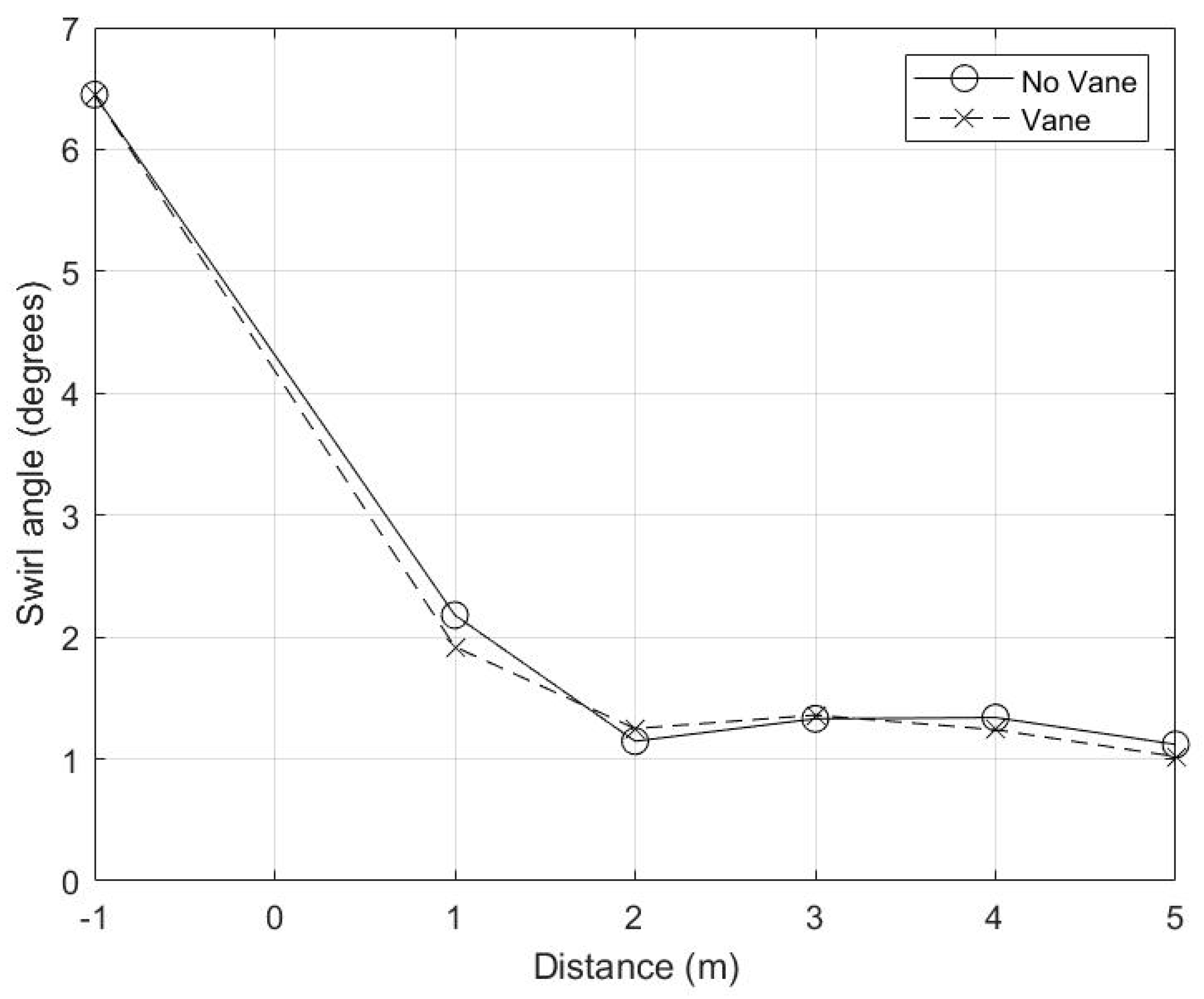
Details of the swirl angle for both designs are shown in
Figure 7. The swirl angle is seen to be similar in the designs with and without vanes. The most significant difference is 1D downstream, where the swirl angle has not quite yet met the 2° criteria for swirl-free flow with the conditioner without vanes, but is just below that for the vaned one. At 2D downstream, this condition is met for both flow conditioners which have both removed the swirl. The swirl angle then fluctuates slightly, but remains under 2° for the range of down-stream distances considered here. This confirms the conclusions drawn from
Figure 6 in terms of the optimal position to place a flow meter. In both cases, the meter can be placed between 1D and 2D down-stream; however, for the conditioner without vanes, the optimal position is closer to 2D and for the vaned conditioner the measurement can be taken as close as 1D, reducing the length of piping required.
The other important consideration is the pressure drop. The pressure drop across the plate, calculated between 1D upstream and 2D downstream, was 496 kPa for the vaneless plate and 688 kPa for the vaned plate, both somewhat higher than the 265.4 kPa for the Zanker plate which was used in the validation. The increased pressure drop is a trade-off for the quality of the axial velocity profile. The quality of the profile is more important in cases where an accurate flow measurement is of overriding importance.
4. Conclusions
A new design of flow conditioner has been proposed. Two configurations, with and without vanes, were simulated using CFD. The results showed that both performed well, compared to existing designs, and that the vaned design slightly outperformed the other. The results indicate that the vaneless conditioner provides suitable conditions for flow measurement within 2D and the vaned conditioner within 1D. The swirl angle was just below 2° for the vaned conditioner, and slightly above 2° for no vane case at 1D down-stream. Further downstream, there was little difference in the swirl angle, which remained between 1° and 1.5° up to 5D. There is a pressure drop produced by both conditioners, which was 496 kPa and 688 kPa for the vaneless and vaned systems, respectively.
As noted in
Section 2.4, there are a number of desirable properties for a flow conditioner, some of which can be contradictory, meaning that it is not possible to achieve optimal performance in each area. Here, the focus was on producing an appropriate axial velocity profile within a short distance of the conditioner. The results show that this was achieved, while also achieving additional properties, such as a reduction in swirl. However, it is also clear from the velocity profiles that the profile is not uniform in the azimuth direction, and the pressure drop is significantly larger than was produced by the Zanker plate in
Section 2.3. In an application where reducing the pressure drop or producing a more symmetric axial velocity profile is paramount, an alternative design could be preferable.
Further work is required to experimentally verify the enhanced performance obtained here through simulation, either in a lab-based environment or in an industrial application. It would also be of interest to investigate the time-dependent performance of the flow conditioner when subjected to features which are encountered in industrial applications, such as blocking [
19], vibration [
25], erosion [
26] and liquid accumulation [
27]. Additionally, the improved performance, observed here in terms of the short distance down-stream of the conditioner at which an accurate flow measurement can be made, comes at the cost of a larger pressure drop across the conditioner. Further work is required to investigate whether the same improved performance can be achieved with a lower pressure drop.


