In this paper, we attempt to solve the problems of the conventional method with a method that enables adaptive routing (Proposed Method 1) and a method that enables the passage of FBs (Proposed Method 2) for (b) fault-tolerant routing.
3.1. Definitions
For the description of the proposed methods, we give the following definitions.
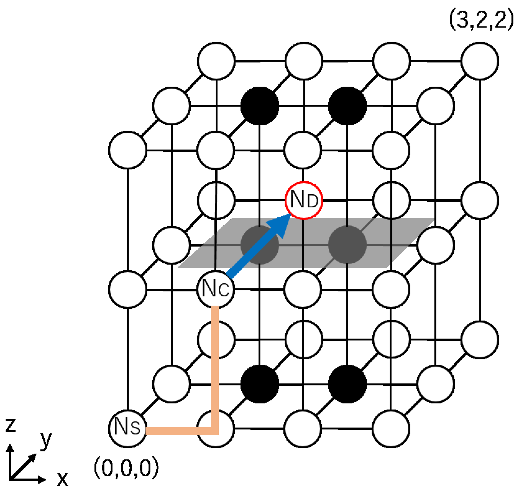
Definition 3. The source node and the destination node of a packet and the current node where the packet currently exists are defined as , , and , respectively.
Definition 4. Let the directions of east, west, north, south, up, and down be and and denoted by E, W, N, S, U, and D, respectively.
Definition 5. A change in the movement direction of a packet is defined as a turn. There exist 24 possible turns, as shown in Figure 4. For example, in an NE turn, a packet changes its moving direction from N to E at a router. Definition 6. There are eight diagonal directions, and the set of all diagonal directions is defined by {}.
Definition 7. Let be the set of possible directions to take the shortest path from a node i to a node j.
Definition 8. For a node i, let the direction of node j be .
3.2. Minimal Fully Adaptive Routing
Boppana’s method uses two different routing methods, routing (a) and (b), as explained in
Section 2.4. For routing (a), minimal fully adaptive routing is used; however, their paper [
3] does not mention the detailed routing rules. In this section, we briefly explain the minimal fully adaptive routing,
, used in this paper.
performs adaptive routing by choosing a neighbor node at to take the shortest path from to . Algorithm 1 shows the algorithm of . First, for a packet originating at a source node , a VC to be used is determined according to (line 3 in Algorithm 1). Then, the packet can choose either one of the neighbor node directions from (line 8). For example, in the case of , {}, which means that a packet can proceed in direction E, N, or U.
The VC selection algorithm for is shown in Algorithm 2. The eight diagonal directions defined by are divided into four groups of two directions, each of which uses four different VCs (i.e., VC0∼VC3) to configure four VNs (lines 3–10). As for a direction d other than the diagonal ones, e.g., E and , any diagonal directions that include d are valid. For example, if , the VCs for , or , i.e., VC0∼VC3, can be chosen. If , the VCs for or can be chosen. Note that a determined VC is not changed when routing (a) is performed.
We now prove the deadlock freeness and 100% packet reachability of the presented .
Theorem 1. shown in Algorithm 1 is deadlock-free in fault-free 3D mesh NoCs.
Proof of Theorem 1. A deadlock occurs when several packets wait for one another to move forward (i.e., circular waiting). We show that circular waiting never occurs in both the clockwise and counter-clockwise directions in .
As shown in Algorithm 1, uses four VCs (i.e., VC0∼VC3) to configure four VNs in the original network. For a packet from to , once a VC is determined, it is never changed until the packet arrives at (line 3 in Algorithm 1), which means that the four VCs (i.e., VNs) are mutually independent.
First, we focus on VC0. In the VN configured by VC0, only packets whose
or
are routed. For
, NE and EN, UE and EU, and UN and NU turns occur in the
,
, and
planes, respectively. For
, SW and WS, DS and SD, and WD and DW turns occur in the
,
, and
planes, respectively. Even if all of these turns occur in one VN, they never cause circular waiting in the clockwise and counter-clockwise directions, as shown in
Figure 4.
A similar statement as above holds for VC1∼VC3. Thus, is deadlock-free. □
Theorem 2. shown in Algorithm 1 provides 100% packet reachability in fault-free 3D mesh NoCs.
Proof of Theorem 2. As shown in Algorithm 1, always chooses a neighbor node from (line 8 in Algorithm 1). In other words, packets always move closer to . As the network is regular and there exist no faulty nodes, a packet originating at eventually reaches . This holds for any and . □
| Algorithm 1 Algorithm of . |
- 1:
function Minimal fully adaptive routing() - 2:
if is then - 3:
= VC_select(, ) - 4:
end if - 5:
if is then - 6:
consume the packet - 7:
else - 8:
randomly choose a direction - 9:
return d - 10:
end if - 11:
end function
|
| Algorithm 2 VC selection algorithm of . |
- 1:
function VC_select(, ) - 2:
- 3:
if d is ENU or WSD then - 4:
= VC0 - 5:
else if d is ESU or WND then - 6:
= VC1 - 7:
else if d is WNU or ESD then - 8:
= VC2 - 9:
else if d is WSU or END then - 10:
= VC3 - 11:
end if - 12:
return - 13:
end function
|
3.3. Adaptive Fault-Tolerant Routing Method (Proposed Method 1)
We propose an adaptive fault-tolerant routing method, referred to as Proposed Method 1. This method also creates FBs in the same way as the conventional Boppana method [
3], and it consists of the following two routing types:
- (a)
Minimal fully adaptive routing: ;
- (b)
Fault-tolerant routing: .
The difference between Proposed Method 1 and Boppana’s method is the adaptive fault-tolerant routing, . also uses the same number of VCs as in the conventional method; however, the method of using the VCs is different. With the same number of VCs, Proposed Method 1 allows the adaptive detour of FBs to shorten the distance from to .
As in the conventional method, when the routing is switched from (a) to (b), i.e., when the selection of the shortest paths becomes impossible,
and
exist on a straight line on the
x,
y, or
z axes, and there exists at least one FB between
and
[
3]. Here, we give the following definition.
Definition 9. A node on a straight line passing through and and touching an FB on the opposite side to is defined as . Note that can be the same node as .
The routing algorithm of Proposed Method 1 is shown in Algorithm 3. First, a VC to be used is determined at . As Proposed Method 1 is a fault-tolerant routing method, different VC selections are performed for routing (a) and (b) (lines 4–9). As in the conventional method, is first performed as long as the shortest path can be selected (lines 13–14). When the selection of the shortest path is impossible, is switched to (lines 15–20). Then, a VC to detour an FB is determined according to the direction from to (line 17), and the FB is adaptively detoured by (line 20), so that the shortest detour path can be selected from to (lines 30–31).
The VC selection algorithm for is shown in Algorithm 4. When is initiated, , , and are on a straight line, as in the conventional method; that is, {}. For the six directions, only four VCs are used by sharing VC4 and VC6 among E, N, and U (lines 3, 7, 11–23) and VC5 and VC7 among W, S, and D (lines 5, 9, 25–37). With this careful VC sharing, Proposed Method 1 achieves deadlock freeness and 100% packet reachability, as discussed later.
Figure 5 shows a routing example for Proposed Method 1. In
Figure 5, suppose that a packet is routed from
to
. At
,
and
{
}.
Figure 5 shows an example where
E is chosen as the next node. When the packet arrives at
, the packet faces the FB and no shortest paths can be found. Then, the routing is switched to
. In this example, two detour paths can be chosen, clockwise (solid line in
Figure 5) and counter-clockwise (dotted line). By
, the clockwise detour path is selected because it is shorter, and the packet can arrive at
, detouring from the FB. Finally, the packet arrives at
.
Note that Proposed Method 1 does not always provide the shortest paths. As explained above, if a packet adaptively proceeds in and arrives at , which exists on a straight line to , the routing is switched to to detour from the FB. In this case, the packet deviates from the shortest path. This problem is solved in another proposed method described in the next section.
We now prove the deadlock freeness and 100% packet reachability. Let be Proposed Method 1 shown in Algorithm 3.
Theorem 3. is deadlock-free in 3D mesh NoCs.
Proof of Theorem 3. As shown in Algorithm 3, consists of two routing functions, and ; is first adopted to proceed along the shortest path adaptively, and then it is switched to to detour around FBs. As long as is adopted, the deadlock freeness is guaranteed by Theorem 1. Hence, we discuss the deadlock freeness of .
When is switched to (i.e., ), and are on a straight line on either the x, y, or z axis, and there exists at least one FB between and (i.e., {}). detours from the FB using four VCs, VC4∼VC7, as shown in Algorithm 4.
First, we focus on VC4, in which packets with
are routed (line 3 in Algorithm 4). In this case, although several possible turns occur to detour around the FB (i.e., EN, NE, ES, SE, UE, EU, DE, and ED turns), packets do not return in the opposite direction (i.e.,
). Hence, circular waiting never occurs. VC4 is also used to route packets with
(line 10 in Algorithm 4). In this case, several possible turns occur to detour around the FB (i.e., UE, UW, NU, and SU turns), as in the case of
. Even if all of these turns occur in one VN simultaneously, they never cause circular waiting in the clockwise and counter-clockwise directions, as shown in
Figure 4.
A similar statement as above holds for VC5, VC6, and VC7; thus, is deadlock-free. □
Theorem 4. provides 100% packet reachability in 3D mesh NoCs.
Proof of Theorem 4. is proven to provide 100% packet reachability in Theorem 2. Hence, we discuss the packet reachability of .
When is initiated, , , and are on a straight line, and there exists at least one FB, as explained before. surely detours around the FB from to , selecting the shortest path, as the network is connected. If there exist FBs between and , similar detours to the above are repeated by , eventually arriving at .
Thus, provides 100% packet reachability. □
| Algorithm 3 Algorithm of Proposed Method 1. |
- 1:
function Proposed Method 1(, ) - 2:
- 3:
if is then - 4:
if then // routing (a) - 5:
= VC_select(, ) - 6:
else // routing (b) - 7:
- 8:
= Proposed_VC_select(, , ) - 9:
end if - 10:
end if - 11:
if is then - 12:
consume the packet - 13:
else if then // routing (a) - 14:
d = - 15:
else // routing (b) - 16:
if is then - 17:
- 18:
end if - 19:
= Proposed_VC_select(, , ) - 20:
d = , - 21:
end if - 22:
return d - 23:
end function - 24:
- 25:
function (, ) - 26:
Find - 27:
if does not exist then - 28:
- 29:
else - 30:
Find the shortest path between and , - 31:
and select d corresponding to the shortest path. - 32:
end if - 33:
return d - 34:
end function
|
| Algorithm 4 Proposed VC selection algorithm of . |
- 1:
function Proposed_VC_select(, , d’) - 2:
if is E then - 3:
= VC4 - 4:
else if is W then - 5:
= VC5 - 6:
else if is N then - 7:
= VC6 - 8:
else if is S then - 9:
= VC7 - 10:
else if is U then - 11:
if detour in plane then // - 12:
if detour in x direction then - 13:
= VC6 - 14:
else // detour in z direction - 15:
= VC4 - 16:
end if - 17:
else // detour in plane: yy - 18:
if detour in y direction then - 19:
= VC4 - 20:
else // detour in z direction - 21:
= VC6 - 22:
end if - 23:
end if - 24:
else // is D - 25:
if detour in plane then // - 26:
if detour in x direction then - 27:
= VC7 - 28:
else // detour in z direction - 29:
= VC5 - 30:
end if - 31:
else // detour in plane: yy - 32:
if detour in y direction then - 33:
= VC5 - 34:
else // detour in z direction - 35:
= VC7 - 36:
end if - 37:
end if - 38:
end if - 39:
return - 40:
end function
|
3.4. Passage-Based Fault-Tolerant Routing Method (Proposed Method 2)
Aiming at guaranteeing the shortest paths for all packets, we propose a novel fault-tolerant routing method based on the passage of faulty nodes, referred to as Proposed Method 2 in this paper. This method is an extension of Proposed Method 1. Namely, this method also creates FBs and consists of the following two routing types:
- (a)
Minimal fully adaptive routing: ;
- (b)
Fault-tolerant routing: .
The difference from Proposed Method 1 is . In Proposed Method 1, FBs are adaptively detoured, while, in Proposed Method 2, they are passed through.
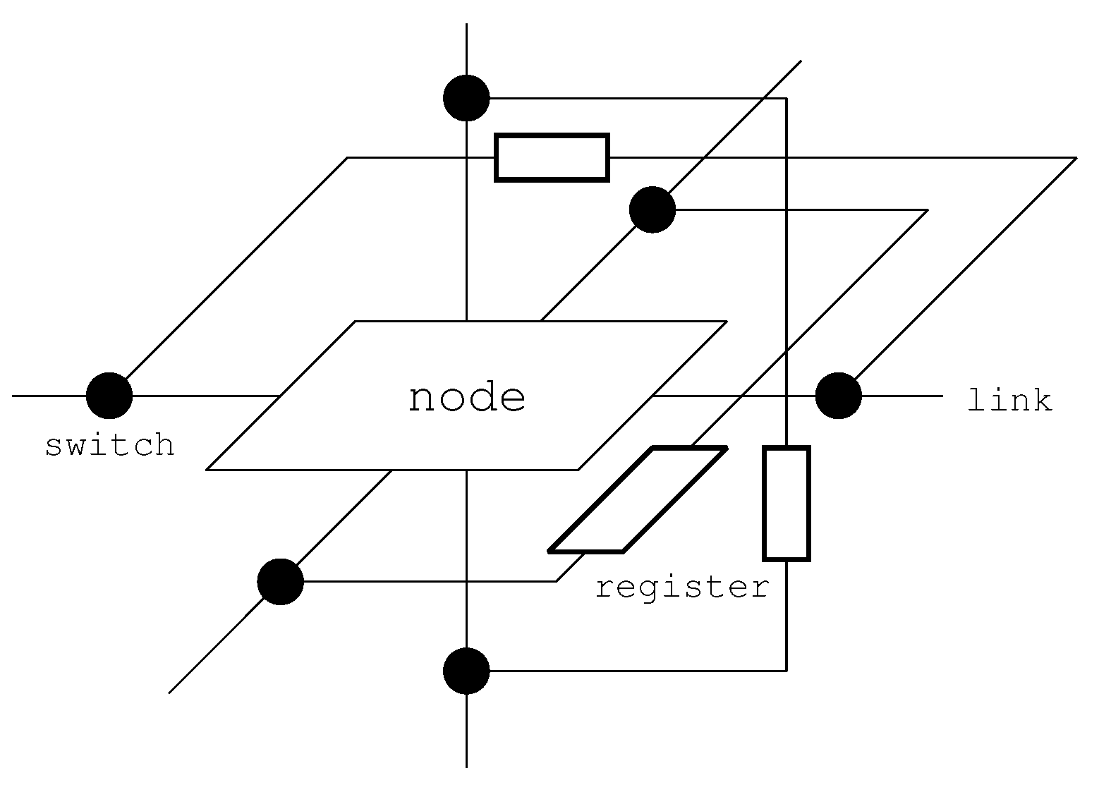
To pass through FBs, the architecture proposed for 2D mesh NoCs in [
12] is extended to 3D mesh NoCs, as shown in
Figure 6. Switches and a link with a register are added to each link connected to the neighbor node in the
x,
y, and
z directions. Once the node is judged as faulty with a circuit test technique, the switches are statically set so that packets are never input to the node and pass through it in the
directions.
The routing algorithm of Proposed Method 2 is shown in Algorithm 5. The structure of the algorithm is almost the same as that of Algorithm 3. When is initiated, there exists an FB between and , as well as . In , packets can pass through the FB and reach directly from . Thus, does not require any VCs, as no turns are needed to avoid FBs, and Proposed Method 2 allows one to always take the shortest path from to .
Figure 7 shows a routing example for Proposed Method 2, for the same example case as in
Figure 5. In this method, the packet proceeds from
to
by passing through the FB.
We now prove the deadlock freeness and 100% packet reachability. Let be Proposed Method 2, shown in Algorithm 5.
Theorem 5. is deadlock-free in 3D mesh NoCs.
Proof of Theorem 5. The proof is straightforward and similar to that of Theorem 3. To avoid redundancy, we provide a simple proof. , which combines and , is proven to be deadlock-free in Theorem 3. is the combination of and , and no turns occur in . Therefore, all possible turns in are a subset of those in . Thus, is deadlock-free. □
Theorem 6. provides 100% packet reachability in 3D mesh NoCs.
Proof of Theorem 6. Again, we provide a simple proof. provides 100% packet reachability, as proven in Theorem 4. The only difference between and is the way in which we proceed from to . As additional hardware such as links, switches, and registers is assumed to be fault-free, passage from to is always possible. Thus, also provides 100% packet reachability. □
| Algorithm 5 Algorithm of Proposed Method 2. |
- 1:
function Proposed Method 2(, ) - 2:
if is then - 3:
= VC_select(, ) - 4:
end if - 5:
if is then - 6:
consume the packet - 7:
else if then //routing (a) - 8:
d = - 9:
else // routing (b) - 10:
d = - 11:
end if - 12:
return d - 13:
end function - 14:
- 15:
function (, ) - 16:
- 17:
return d - 18:
end function
|


