Article

Synergistic Verification of Hardware Peripherals through Virtual Prototype Aided Cross-Level Methodology Leveraging Coverage-Guided Fuzzing and Co-Simulation

1
Institute of Computer Science, University of Bremen, 28359 Bremen, Germany
2
Cyber-Physical Systems, DFKI GmbH, 28359 Bremen, Germany
*
Author to whom correspondence should be addressed.
Chips 2023, 2(3), 195-208; https://doi.org/10.3390/chips2030012
Submission received: 3 July 2023 / Revised: 29 August 2023 / Accepted: 6 September 2023 / Published: 8 September 2023

Abstract

:
In this paper, we propose a Virtual Prototype (VP) driven verification methodology for Hardware (HW) peripherals. In particular, we combine two approaches that complement each other and use the VP as a readily available reference model: We use (A) Coverage-Guided Fuzzing (CGF) which enables comprehensive verification at the unit-level of the Register-Transfer Level (RTL) HW peripheral with a Transaction Level Modeling (TLM) reference, and (B) an application-driven co-simulation-based approach that enables verification of the HW peripheral at the system-level. As a case-study, we utilize a RISC-V Platform Level Interrupt Controller (PLIC) as HW peripheral and use an abstract TLM PLIC implementation from the open source RISC-V VP as the reference model. In our experiments we find three behavioral mismatches and discuss the observation of these, as well as non-functional timing behavior mismatches, that were found through the proposed synergistic approach. Furthermore, we provide a discussion and considerations on the RTL/TLM Transactors, as they embody one keystone in cross-level methods. As the different approaches uncover different mismatches in our case-study (e.g., behavioral mismatches and timing mismatches), we conclude a synergy between the methods to aid in verification efforts.

1. Introduction

Modern design flows for embedded systems deal with the rising complexity by leveraging Virtual Prototypes (VPs). A VP is an abstracted executable model of the entire H a r d w a r e (HW) platform and predominantly created in C++ using the SystemC HW modeling language in combination with the Transaction Level Modeling (TLM) formalism, which serves as communication interface for modeling abstract bus systems [1]. VPs are leveraged for early S o f t w a r e (SW) development and verification in the design flow and also serve as functional reference model for the subsequent HW development stage at the Register Transfer Level (RTL) [2,3,4]. As such, VPs enable to parallelize and integrate the HW and early SW development and verification flows [2].
Verification is a crucial aspect in the HW development phase, since undetected errors will be very costly to fix in later stages. Due to the characteristic differences between processors and peripherals, verification methods cannot be assumed to simply transfer (e.g., verification of a processor vs. a high speed communication peripheral). Since traditional verification starts after the design and implementation process, early verification is a challenge that requires various conditions to be met. While strong, novel, and scaleable verification methods play an important role to handle the ever-growing complexity of new designs, it is paramount for the development processes to seamlessly integrate these methods effectively. With early verification gaining popularity and importance, the bare existence of strong verification methods alone only partially solves the challenge of true early integration of verification efforts into the development process. As VPs exist as early as the specification of a system, they offer a seamless integration not only for development but also in verification efforts.
In this sense, methods like Coverage Guided Fuzzing (CGF), which has proven to be efficient in the SW domain, can be utilized as an integral part of the hardware verification strategy early on [5,6]. While there is an emphasis on verification methods for processors, which is the centerpiece of an embedded system, the verification of peripherals has been comparatively neglected.
Contribution: In this paper we propose a VP-driven verification methodology focused on HW peripherals (see Figure 1 for an overview of the approach). As a case-study throughout the paper, we utilize a RISC-V interrupt controller as our Device under Verification (DUV), demonstrating the seamless utilization of the RISC-V VP [3] and selected verification methods.
We combine two approaches to aid each other in the verification effort and use a VP as readily available reference model:
(A) We utilize CGF enabling comprehensive verification of the HW peripheral with a TLM reference at the unit level (left path in Figure 1). For this approach, state-of-the-art CGF techniques provided by LLVM libFuzzer [7] are employed, demonstrating how the unit-level can be covered for the verification (here the unit-level refers to the DUV without integration into a system). With this approach, three behavioral mismatches were identified within 1 h of run time. Furthermore, we provide a discussion of the discovered mismatches. Since coverage-guided fuzzing is utilized in our case-study, we additionally discuss the achieved coverage metrics (line, branch and function coverage) between the TLM and RTL description.
(B) A co-simulation-based approach allowing application-driven verification of a HW peripheral on a system-level (right path in Figure 1). For that the RTL HW peripheral is integrated into the RISC-V VP that represents the system-level. We can compare the peripherals’ behaviors when executing a FreeRTOS application. In a co-simulation setting, differences in the behavioral description of the TLM and RTL peripheral can introduce mismatches on non-functional dimensions like timing, thus affecting the application execution. By investigating program traces of executed FreeRTOS applications, we identify and discuss timing mismatches.

2. Related Work

Functional verification of HW designs has a long history in using different techniques from simulation-based testing to formal verification approaches [8]. While formal approaches, such as [9,10,11], are obviously desirable to ensure a comprehensive verification process, they are unfortunately susceptible to scalability issues due to state space explosion [12]. Therefore, simulation-based approaches still form the backbone of the verification effort. In particular testbenches that rely on constrained random techniques for input generation and are assessed by coverage metrics play a very important role due to their ease of use and scalability [13]. Best practices in this regard have led to the definition of the Universal Verification Methodology (UVM), which now plays an important role in the design of testbenches at the RTL [14]. Ref. [15] reports a case-study on the verification of a ARM Advanced Microcontroller Bus (AMBA) protocol implementation using constrained random verification in SystemVerilog. Assertions are placed to check for AMBA protocol violations.
While constraint-based approaches can be effective, they require significant effort in order to set up high-quality testbenches. Inspired from the ongoing success story of modern coverage-guided fuzzing techniques in the SW domain, fuzzing has been adopted to enable test generation for HW designs at the RTL [16]. Motivated by the promising results further research has been sparked that optimized the fuzzing approach by employing directed test generation for guidance [17] and taking RTL specific characteristics into account [18]. However, a complete co-simulation with a system-level model is not considered in the fuzzing loop. Ref. [19] discusses general challenges in combining a system-level model with a RTL model in a co-simulation setting from the verification perspective. [20] proposes a co-simulation environment for SystemC and Verilog modules by integrating both simulation kernels and using custom channels on top of the Verilog Procedural Interface for communication. Ref. [21] describes a TLM to RTL UVM-based verification methodology that attempts to re-use the TLM testbenches for RTL verification. Ref. [22] proposes a simulation-based equivalence check for TLM and RTL SystemC models. Beside simulation-based methods, formal equivalence checking between models at different abstraction levels is supported by industrial tools such as SLEC [23], however, the approach is proprietary and formal techniques tend to be susceptible to scalability issues. Recently [5] describes another coverage-guided fuzzing approach in which, compared to [16], RTL instrumentation for coverage tracing is not needed and very generic interfaces for verification engineers are provided for use.
In our paper we enhance the fuzzing based approach with the TLM reference for mismatch detection. Moreover, through the VP-driven setting we allow testing early from the application perspective. We continue to leverage Verilator for the RTL models and enhance the verification through the use of TLM based reference models. This also allows an early evaluation of integrated RTL peripherals on a system-level. Furthermore, the utilization of Verilator enables a speed up for RTL simulations of orders of magnitude compared to traditional event-based RTL simulators [24].

3. Preliminaries

In this section we will provide the necessary background information that is utilized for the proposed methodology. At first, we give a brief overview of the Platform Level Interrupt Controller (PLIC) that is utilized in the case study in Section 3.1. We provide relevant background information on SystemC in Section 3.2. Finally, in Section 3.3 we discuss considerations on RTL-TLM transactors, as they are a key element for cross-level methods.

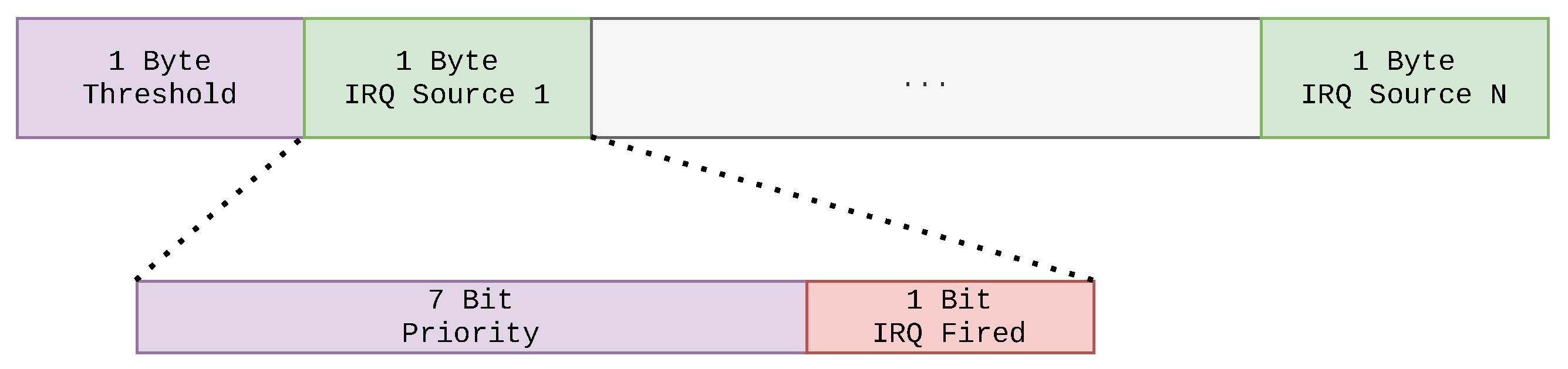
3.1. Platform-Level Interrupt Controller (PLIC)

The PLIC [25] for RISC-V based processors describes an interrupt controller that multiplexes numerous device interrupts to the external interrupt lines of the processor. It was designed to support up to 1023 interrupts and is configurable with thresholds and priorities. Moreover, the PLIC allows to distinguish between different execution modes of the processor, as described in the privileged architecture specification of the RISC-V Instruction Set Architecture (ISA) [26]. Furthermore, up to 15,872 contexts can be handled by the PLIC, each context can either represent a single processor or a single thread within a multithreaded processor core. Inside the PLIC each interrupt source has a designated Identifier (ID) by which it can be addressed. When devices request an interrupt through the PLIC, the combination of priority, threshold, and ID is used to trigger interrupt notifications to each available processing unit. If two interrupt sources have the same priority, the source with the lower ID is selected over the source with the higher ID. A threshold can be set for each context, meaning each processor’s interrupt sources can be finely tuned to the needs of the application in which interrupts from various sources are handled by multiple processors. Lastly, the PLIC features a message sequence to handle interrupts by a targeted processor in order to notify, claim, and mark an interrupt as completed. At first, interrupts are claimed by a processor by reading the designated register from the PLIC, which returns the interrupt ID. Finally, the processor marks the interrupt as completed, by writing the interrupt ID the designated register in the PLIC. Lastly, while the PLIC Specification [25] defines that an arbitrary delay between an incoming interrupt and the notification of the processor is allowed, in this work we consider an interrupt controller with a single cycle delay.

3.2. SystemC

SystemC is a hardware and system modeling language. Initially SystemC provided a formalism that allowed modeling at the RTL. With SystemC TLM [1] an additional modeling formalism inside the SystemC library is introduced that allows a higher abstraction in component modeling. The TLM formalism allows modeling interactions between modules as whole transactions, abstracting from the I/O pins used in RTL interfaces. While communication between RTL modules involves specific sequences on the I/O interfaces between them, the TLM abstraction encapsulates this behavior into a function call. Commands and payloads are passed as the functions parameters and are made available at the routing- and end-points. The TLM 2.0 standard [27] defines designated interfaces to model generic transactions with varying levels of detail. If only the sequence of communication between modules is synchronized, the TLM standard terms this style loosely-timed. A more detailed approach introduces timing points for protocol-specific behavior that demark phases of protocols, this style is termed approximately-timed. These modeling styles allow the developer to have a range of mechanisms (e.g., Direct Memory Interface (DMI), global quantum, blocking vs. non-blocking transport, etc.) to model fast or detailed TLM simulation models. Compared to the traditional RTL communications the TLM communication enable increased simulation speeds.

3.3. RTL-TLM Transactors

As mentioned earlier one difference between the RTL and TLM level is the abstraction of interfaces. In RTL interfaces are described as signals connecting to other modules, that way data busses and control signals are realized. In the TLM style interfaces are abstracted into sockets that act on function calls with commands and payloads encapsulated in transactions. Specific sequences and timings of the RTL interfaces are simplified and allow the TLM simulation to boost the simulation speed. Additionally, the notion of time in RTL is represented through clocks and clock cycles. For TLM, the notion of time is achieved by annotating events and function calls with associated delays. Furthermore, the TLM coding styles also allow for a more detailed representation of bus transactions with multiple phases and timing points. This allows TLM representations to offer either fast or detailed simulations. The flexibility of the TLM coding styles allows closing the gaps between TLM and RTL models if the VP design requires it.
For the cross-level technique, the verification engineer has to be aware of this abstraction technique. If a module is transformed from RTL to TLM, a wrapper (called transactor) has to translate the function calls with their payload to the RTL signal sequences. Vice versa, the RTL signals and sequences have to be mapped to the respective TLM equivalents. The TLM timing annotations have to be used within the wrapper to synchronize to the RTL clock with the rest of the simulation. Co-simulating TLM and RTL requires a separate clock thread for the RTL peripheral in place. One possible way to translate a TLM transaction to the respective RTL sequence is to use a blocking transport and unroll the transaction to the signal sequences throughout the clock cycles of the RTL clock, then returning the blocking transport to the TLM initiator.

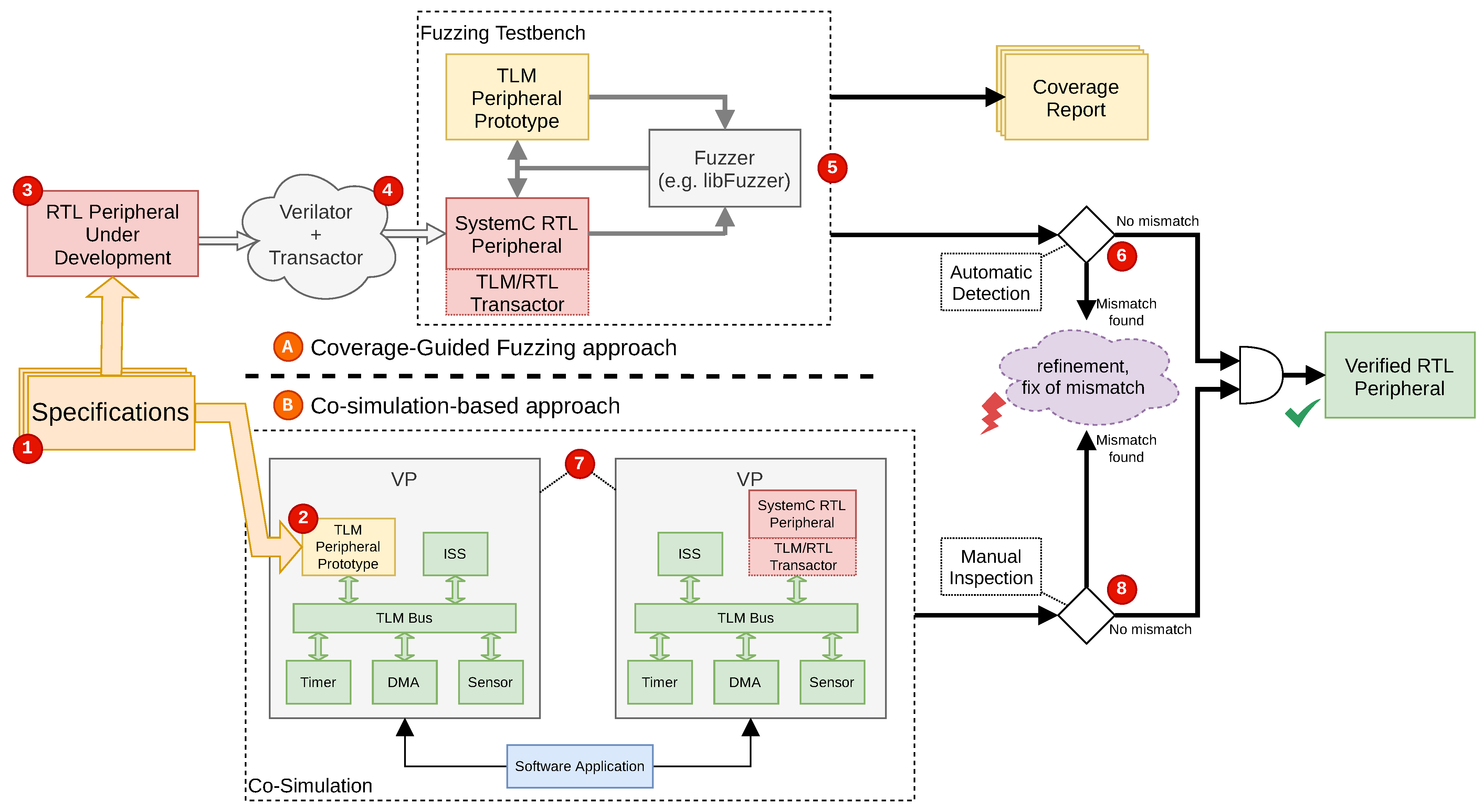
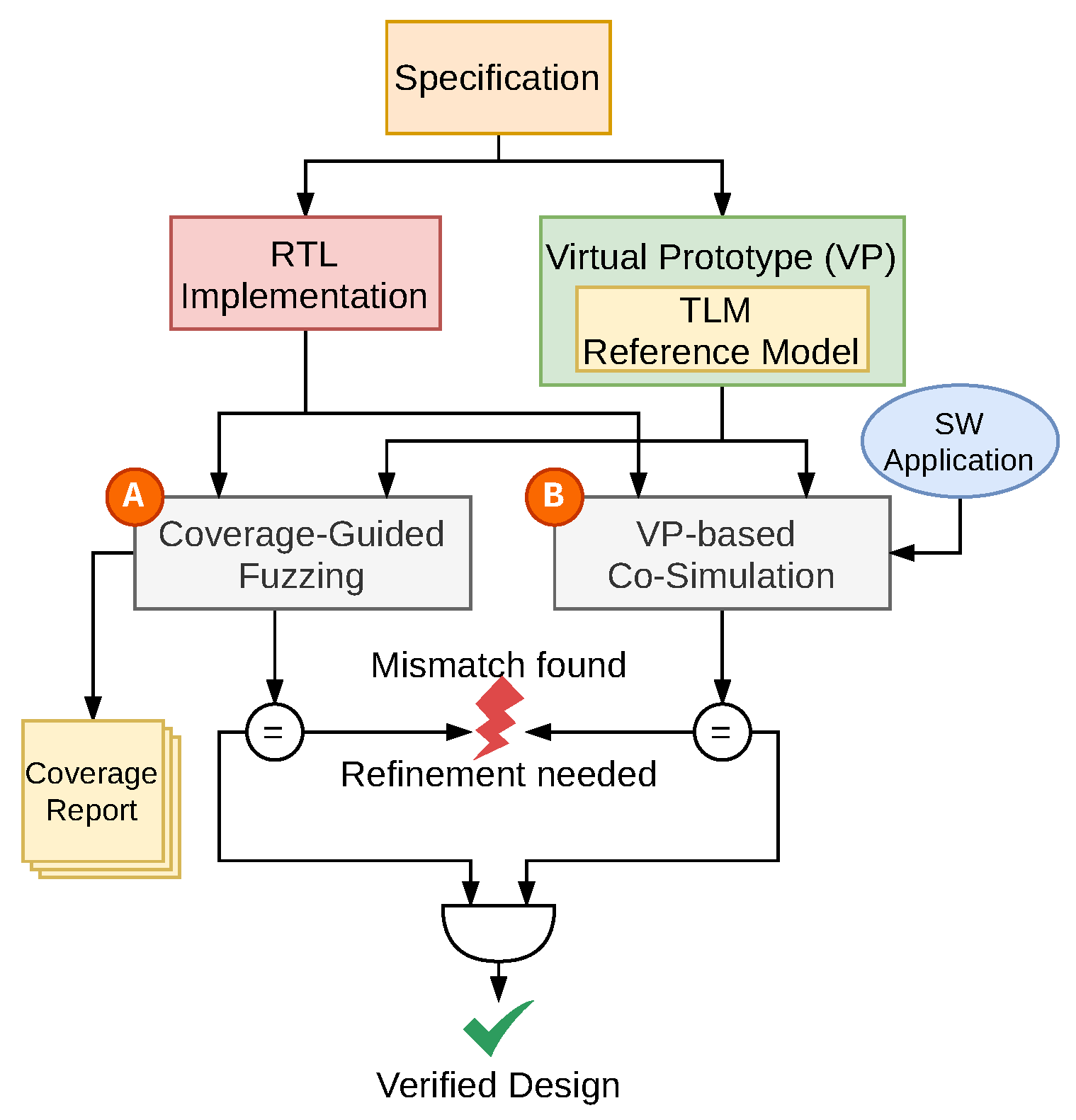
4. Hardware Peripheral Verification Methodology

Our proposed methodology incorporates a combination of verification strategies to achieve the Cross-Level Verification (CLV) and application driven co-simulation. Starting in Section 4.1, we give an overview on our methodology as a whole. Section 4.2 follows up with a discussion on the CLV setting. In Section 4.3 we discuss the mapping of the generated values of the CGF to the DUV. Finally, Section 4.4 discusses the details of the application driven co-simulation setting.

4.1. Overview

Figure 2 shows an overview of our methodology employed for the CLV strategies. The CGF approach (Ⓐ) is shown at the top and the application driven co-simulation approach (Ⓑ) is shown at the bottom of the figure, respectively. The overview of the CLV methodology reads along the circled numbers ➀ to ➇ within the figure. At first, the specification (➀) is realized at the TLM abstraction level inside a VP (➁). The TLM-based peripheral prototype serves as a reference in the RTL development. To develop the RTL peripheral (➂) the specification and the TLM peripheral are used as references. Through the Verilator tool and a RTL-TLM transactor (➃), we transform the RTL peripheral into SystemC RTL, enabling usage with TLM transactions. From here on the methodology can be taken apart into the CGF approach (➄ and ➅) and the co-simulation-based approach (➆ and ➇).
For the CGF approach (Ⓐ), the CGF testbench (➄) integrates the TLM and RTL peripheral. The CGF (e.g., by utilizing LLVM libFuzzer) generates input and applies these to the peripherals in order to evaluate the modules for behavioral mismatches (➅). Upon detection of a mismatch, the specific input sequence uncovering the mismatch can be utilized by the engineer in the debugging process. Furthermore, we obtain a coverage report on both the TLM and the RTL peripheral to assess the quality and completeness of the generated inputs in terms of line, function, and branch coverage.
For the co-simulation-based approach (Ⓑ), the transformed RTL peripheral is used as a drop-in replacement for the TLM peripheral inside the VP. Thus we obtain a reference VP, with the TLM peripheral and a modified VP with our DUV residing within. In this co-simulation setting a software application can be executed on both VPs (➆) and the mismatches (including non-functional mismatches like timing issues) can be identified (➇). Checking for mismatches in the application driven co-simulation setting occurs in manually for this work. If mismatches are found the implementation can be refined, fixed, and retested until no more mismatches occur.
Only if both approaches show no mismatches we consider the RTL peripheral verified. The additional detection of non-functional mismatches (e.g., timing issues within the system due to the peripheral) of approach Ⓑ complements the pure behavioral/functional verification approach Ⓐ. Furthermore, the CGF approach Ⓐ can be considered to operate on the unit-level, within the scope of the module and not. Whereas the application driven co-simulation-based approach Ⓑ operates on a system-level by integrating the RTL peripheral into the full VP. We believe both approaches complement each other and further reduces the development time, until full integration in the RTL takes place. In Section 5.1 and Section 5.2 we elaborate our experimental setup and evaluate the CGF verification (Ⓐ) as well as the co-simulation (Ⓑ) respectively.

4.2. Cross-Level Environment for Coverage-Guided Fuzzing

The first strategy in our cross-level verification incorporates CGF. By leveraging the transformation of the RTL peripheral into the SystemC TLM domain, we can effectively utilize modern and industry proven methods like CGF for hardware verification. CGF allows us to drive the inputs of the DUV in a randomized manner. The DUV reports the coverage these generated inputs achieve, allowing the fuzzer to generate new mutated inputs with the goal of increasing the coverage metrics.
While the transformed RTL model offers some coverage metrics (e.g., line coverage, branch coverage, etc.), it is still relatively open to research how the coverage on the transformed model translates down to the RTL design [5]. The coverage term has a slightly different terminology for RTL descriptions than for SW. As the RTL describes a digital circuit that is not executed sequentially but in parallel at any point in time, while SW is executed sequentially line by line. In the RTL domain coverage often refers to a functional coverage or different types of coverage metrics like signal toggle coverage. These differences contribute to the difficulties assessing the same meaning to the coverage metrics across layers of abstraction.
For our approach, the SystemC simulation kernel required additional modification which we will discuss briefly. By default, the SystemC simulation kernel does not support a reset of the simulation within the same simulator execution. In order to support a reset, the global simulation variables are handled and a reset is executed, as the regular SystemC simulation kernel was not designed with that in mind. Our approach itself is agnostic to the coverage-guided fuzzer, but for this work in particular we choose LLVM libFuzzer. For that, the LLVMFuzzerTestOneInput method has to be implemented as an entry point for the coverage-guided fuzzer. In this method the SystemC simulation is set up and if it already ran, the simulation state has to be reset properly. The generated inputs are fed into both, the SystemC TLM peripheral and the transformed SystemC RTL peripheral in order to run a simulation. During simulation the outputs are compared and on a mismatch the CGF throws an exception, otherwise it generates another set of inputs and calls the simulation for both peripherals.

4.3. Input Mapping & Test Scenarios

The coverage-guided fuzzer generates an endless stream of bytes, that has to be mapped onto the inputs of the modules to create test scenarios.
Figure 3 shows how the generated stream maps onto the PLICs functions. The first byte (Threshold, purple) is used as the priority threshold value of the PLIC, signaling which interrupt priorities can trigger a processor interrupt. The following byte (IRQ Source, green) is utilized as an interrupt source, split into 7 bit encoding the priority (Priority, purple) of that interrupt and 1 bit encoding whether it is currently activated as an interrupt input of the PLIC (IRQ Fired, red). Such IRQ Source bytes repeat for as many interrupt sources are declared. These bytes then become part of the TLM transactions, SystemC events, and SystemC RTL inputs for the TLM reference and DUV, respectively.
Cross-level methods also requires additional attention for both RTL and TLM versions of the peripheral. At TLM the abstraction from signal lines to abstract interfaces between modules eases handling protocols and handshakes, as these will be the transaction to and from a module. Applying fuzzer input data means varying the function parameters and payloads. At the RTL, protocols and handshakes are represented in sequences of signals with their corresponding signal levels. Thus, the fuzzer could often generate invalid sequences or the fuzzer inputs have to serve as the basis to choose different transactions. For example, instead of generating the control signals that finally lead to a complete write transaction, the fuzzer generated bits can encode a transaction command (read or write) that can be decoded to the transaction sequence that is then executed for a set of fuzzer generated inputs. At first sight, both options (fuzzer induced transactions and directed transactions) have advantages and disadvantages. If the fuzzer could induce transactions that invoke a wrong sequence of signals, faulty handshake and protocol handling can be detected. At the same time, creating valid positive test cases will happen less often. If the CGF is guided to always trigger a transaction but never cause faulty handshake and protocol attempts, the test cases cannot detect issues in the protocol handling. At the same time, the functional behavior of the peripheral is inspected with the effectiveness of CGF. Such trade-offs are covered by traditional constrained random approaches, due to the possibilities to describe constraints, relaxations for these constraints and probability distributions for cases of constraints (e.g., faulty transactions can be part of the test set). Without attention to these details the verification engineer easily could run into wrong assumptions about the results or the effectiveness of an approach.
For our case-study with the PLIC, we map the CGF-generated inputs to the interrupts inputs and create respective bus transactions, writing the configuration registers of the PLIC (e.g., if the fuzzer decides to enable a certain interrupt, the respective transaction on the bus will be initiated). For a set of inputs (e.g., interrupts, enables, thresholds and priorities) we compare the behavior of the TLM and RTL peripheral.

4.4. Application Driven Co-Simulation Environment

The application driven co-simulation environment is set up as the second strategy in our CLV methodology. By utilizing a VP, the DUV can be integrated in an early development stage to reduce the time until system-level verification. Through an application driven co-simulation of the VP early software can be utilized as use cases, and add further momentum to the development cycles. Contrary to the CGF approach, in the co-simulation environment the peripheral is interconnected with other modules. The previously introduced RTL-TLM transactor can be reused for the bus interconnect of the peripheral, this part of the transactor is universal across different peripherals. Existing TLM peripherals can therefore be drop-in replaced with their RTL counterparts. As the co-simulation within a VP environment features a system-level model of the System-on-Chip (SoC), additional non-functional aspects like timing behavior can be considered. In contrast to CGF the DUV is driven indirectly and with narrower set of possible inputs through the software application but offers a system integrated observation that features the interaction with other modules and the possibility to consider further non-functional aspects like timing behavior. Therefore, application driven co-simulation nicely complements the CGF approach.
For our case-study with the PLIC, we utilize the RISC-V VP [3] and an existing FreeRTOS application, which utilizes external interrupts. The PLIC is connected to all peripherals offering external interrupts to the CPU, thus the use case of this application heavily depends on the funcitonality of the DUV. This application is executed with the TLM peripheral as well as the DUV on the RTL. For this purpose a modified copy of the VP with the RTL peripheral is prepared. As the RTL peripheral runs on a different abstraction the effect of the clock timing is observed in relation to the TLM based VP. As further introspection and inspection is required to analyze a complex SoC model executing an application with FreeRTOS we utilize the Tracalyzer (See https://percepio.com/tracealyzer/ (accessed on 7 September 2023) for more information) to collect timestamped traces of the application execution. We use the existing TLM as a reference for the timing behavior, and prepare the RTL to be executed on a range of clock periods to observe the possible effect on the simulation timings.

5. Evaluation

This section presents and discusses the evaluation of our CLV methodology with respect to our case study. For the case study a RISC-V PLIC is implemented, which serves as an external interrupt controller. A PLIC informs available RISC-V processors about external pending interrupts from peripherals (e.g., a serial interface, timer, etc.). The PLIC interface uses a set of inputs and outputs (interrupt signals from peripherals and an output signal to the processor to signal one or more pending interrupts) and a bus interface via which the controller is configured and pending interrupt requests are claimed. We think this peripheral is a reasonable case study as the complexity covers:  
(a)
handling bus transactions,
(b)
timing specific behavior (e.g., incoming interrupts have a specified maximum delay to reach the processor), and
(c)
handling I/Os with configurations (e.g., enable, priorities, etc.).
Another aspect of the case-study is the VP, for which we use the open source RISC-V VP [28]. The RISC-V VP operates on the TLM abstraction and thus is suited to serve in exploring our previously described methodology. For the case-study, the bus model of the VP on the TLM is used to derive a compatible RTL interface that allows the PLIC to be interconnected into the system. Through Verilator the RTL description is transformed from Verilog into SystemC and afterward connected via the RTL-TLM transactor for (A) the CGF methodology and afterward for (B) the application driven co-simulation environment. For the CGF LLVM libFuzzer is utilized to fuzz the modules.
The next sections cover the experiments and verification results for the PLIC peripheral obtained by applying our CLV methodology. Section 5.1 covers the CLV with CGF, in which the TLM-based PLIC is utilized as a reference for the RTL-based PLIC. In Section 5.2 we cover the application driven co-simulation inside the VP with FreeRTOS as an industry grade application example. Our experiments were executed on an AMD Ryzen 9 5900X @ 4.8   G Hz with 64 G RAM running on Ubuntu 20.04 LTS. The RTL-based PLIC is configured with up to 53 incoming interrupts and a maximum priority of 7, resulting in a total of 324 bit of register bits, spread across 60 registers, 124 input bits (across 59 signals) and 34 output bits (across 3 signals).

5.1. Verification via Coverage-Guided Fuzzing

The CGF with libFuzzer was executed for a run time of 1 h. To implement the required function that applies the CGF generated inputs to the DUV, we additionally modified the SystemC simulation kernel significantly to support multiple simulation runs within a single simulation context. For the run time of 1 h the CGF generated 39,445 input sequences and detected three mismatches which will be further discussed in this section. These mismatches were identified through the following behavior:
1.
Two mismatches in the claim/complete behavior of the PLIC;
2.
The order of the interrupt priority is handled wrong.
For 1 the mismatches lay in handling the claim/complete process of the pending interrupts. The PLIC specification [25] defines, that handling an interrupt consist of a two-step process. First, a processor claims the interrupt at the interrupt controller (and in this process receives the respective interrupt ID). Second, the processor notifies the interrupt controller about the completion of the claimed interrupt with the same interrupt ID. A mismatch of this behavior was identified. In particular, on the TLM side any ID was accepted to complete the described process. This was fixed to support only those IDs which (according to specification) are enabled in the interrupt enable register. After re-running the CGF another mismatch of the same type was found. In this particular case the behavior of the RTL implementation was too strict, as it only accepted the exact interrupt ID which was pending. This too was refined to support those interrupt IDs which are currently enabled.
For 2 consider the scenario of two interrupts arriving at the PLIC: Both interrupts arrive at the same time but have differently configured priorities. Table 1 shows the mismatch for this scenario between the TLM and the RTL module. The table shows how the same scenario is interpreted for the TLM PLIC (top part of the table) and for the RTL PLIC (bottom part of the table). Each interrupt consists of an ID, a priority, a masked priority, and lastly an order which interrupt is handled first and second. According to the specification, the interrupt with the ID 1 should be triggered at first, because the masked priority is higher than the one with the ID 1. This behavior was implemented correctly in the TLM design but was identified as a bug in the RTL implementation. In these cases, the verification strategy employing CGF uncover mismatches in both TLM and RTL and allowed for quick retesting of the inputs causing the mismatch to occur.
Additionally, the CGF process collects coverage as libFuzzer guides the input generation with the obtained coverage metrics. Table 2 shows achieved coverage metrics after a run time of 1 h . The table is split into three parts. The left part shows the description of each coverage metric presented. The middle part show the coverage statistics for the TLM implementation. The right part show the coverage statistics for the RTL implementation. The middle and right part have the same columns regarding the coverage metrics. The second and fifth column show the amount of hits for a coverage metric, the third and sixth column show the available cover points and the fourth and seventh column show the relative percentage of hit cover points to available cover points. For the TLM PLIC a line coverage of 98.3 % , a function coverage of 100% and a branch coverage of 61.0 % were achieved. On the RTL PLIC a line coverage of 86.3 % , a function coverage of 83.3 % and a branch coverage of 73.7 % were achieved.
For both implementations there exist remarks regarding the interpretation of the coverage metrics which should be noted here. In TLM, the memory mapped registers are generated through an abstracted generator which does not allow to directly identify which registers were written and read by means of coverage alone. This means writing memory mapped registers are possibly covered through the CGF generated inputs, while functional coverage is required to cover different register values specifically. In contrast, for the RTL implementation, the memory mapped registers are not generated in such a manner and thus are available in a different traceability for the coverage metrics. Due to the SystemC RTL implementation being generated through the Verilator tool, the amount of Lines of Code (LoC) is significantly higher. Optimizations in the code generation cause some branches to be combined into nested ternary statements. Reaching such a branch and maybe activating it once can be done through within CGF, but it will not cover the complexity that these nested statements provide. Generally, it is advised to not only work with the line coverage [29,30], and due to the big difference in LoC between the TLM (121 LoC) and the RTL (3212 LoC) implementations.
Through CGF approach a reasonable high degree of coverage is achieved within a run time of 1 h . With the TLM reference from the VP-aided development, we can additionally find mismatches between the available peripheral models.

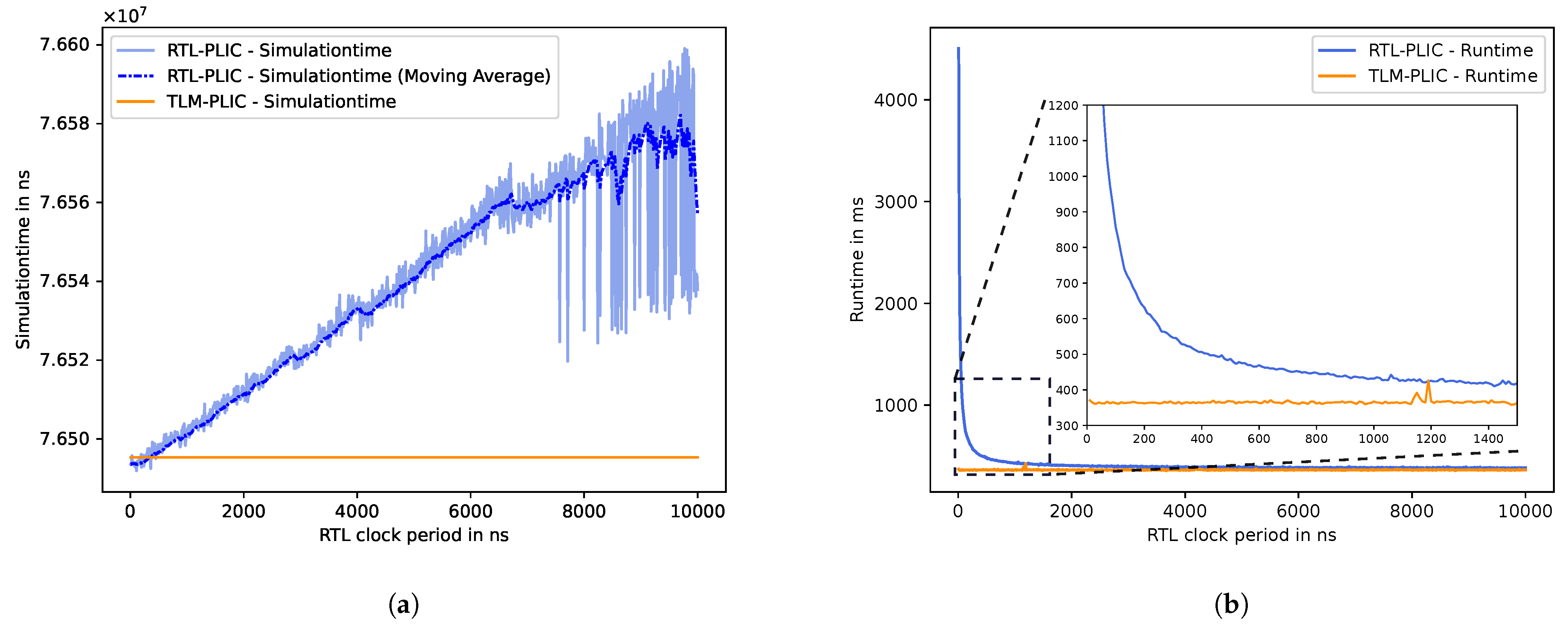
5.2. Verification via Application Driven Co-Simulation

For the application driven co-simulation, an existing FreeRTOS application utilizing external interrupts from the RISC-V VP is utilized and executed with the TLM and RTL peripheral in place, respectively. Additionally, other features of the system architecture (e.g., timer interrupts, serial interfaces, etc.) are utilized to embed the implemented peripheral inside a system-level scenario. The FreeRTOS application therefore acts as a system-level use case and utilizes the peripheral in a realistic scenario. To inspect the FreeRTOS application, we instrument it with the Tracealyzer tool in order to record the application traces for each VP. Obtained traces are manually compared for functional and non-functional mismatches like timing behavior. Additionally, we measure the total execution time and performance for various RTL clock speeds to gain insights on the impact of the additional simulation overhead. For this, we run the FreeRTOS application for clock periods between 10 n s and 10,000 n s in increments of 10 n s . Executing the VP with the FreeRTOS application for all clock periods takes around 7 min.
Figure 4 shows the collected performance for the TLM and RTL based PLIC utilization in the VP for the internal simulation time (Figure 4a) as well as the total execution time on the host system (Figure 4b). Figure 4 a shows how the internal simulation time changes with respect to the SystemC RTL clock period. The blue lines represent the simulation with the RTL PLIC peripheral as part of the VP simulation. While the light blue represents the raw collected data, a darker dotted blue line is added as a moving average in order to make the trend more visible and the plot more readable. The orange line represents the pure TLM-based simulation, which always remains at the same simulation time as no RTL clock is utilized. An increase in the simulation time can be explained through the application awaiting the responses from the PLIC peripheral. A slower clock causes longer times for handling bus interaction and incoming interrupts. It should be noted, that the increase is in the order of 80 μ s while the total execution time is in the order of 75 m s . But this deviation of the internal simulation time caused through the RTL clock still affects the non-functional behavior on the application traces.
Figure 4b shows the execution time of the simulation on the host system. The blue line represents the run time with the RTL PLIC inside the VP, while the orange line shows the run time with the TLM PLIC. For better readability of the graph a zoomed frame shows the clock periods up to 1500 n s as the majority of run time change can be observed for these clock periods. For very small clock periods (e.g., below 500 n s ) the SystemC thread of the RTL clock requires the simulation kernel to perform many additional context switches while progressing other threads. Relating to Figure 4a to Figure 4 it can be concluded that small clock periods are necessary to achieve more accurate simulation times, that also affect non-functional aspects like signal and event timings. In summary, the cost for this accuracy is the additional run time for the additional RTL simulation and clock threads. For longer RTL clock periods the total run time of the simulation is close to the pure SystemC TLM-based simulation. Analogously, the internal simulation time and respective signal and event timings might experience inaccuracies though when fast simulation run times are desired. This trade-off is essential when using TLM-based modeling simulation techniques but not necessarily expected when introducing cross-level techniques into the simulation.
Table 3 shows the Tracealyzer logs for the co-simulation with the FreeRTOS application using interrupts and thus employing the interrupt controller. The table is split into two parts. The left part shows time stamps for TLM simulation, and two RTL simulations one with 10 n s clock and one with 100,000 n s clock. The resolution of the timestamps is given in μ s . The right part shows the actor and event for a particular time stamp. For example the first line of the trace shows that at the timestamp of 74 μ s (80 μ s for RTL 100,000 n s respectively) the actor Task 1 triggers the event of a context switch on the CPU into Task 1. In the table the actors are application two tasks (Task 1 and Task 2) as well as the FreeRTOS meta task (#WFR) for handling and scheduling tasks and other events.
The TLM-based simulation provides the baseline that can be compared with the RTL simulations. The RTL simulation with a clock period of 10 n s follows the TLM simulation in lockstep. RTL with 100,000 n s lags behind the events due to its late synchronization (and loses a time stamp around 167 μ s reference time), but can be executed almost with the same host system execution time as the TLM simulation. While functionally covering the same tasks in the same order, the non-functional aspects like timings change, which in turn would require the faster clock periods with the higher simulation run time.
Such non-functional aspects only become visible on a system-level integration and not during the unit-level. With the VP-aided development flow, the RTL peripherals can be integrated early into a full (prototype) system and checked for possible non-functional faults and mismatches. At the same time, the system-level also allows errors to be visible if execution traces of RTL and TLM peripherals and their system interaction is compared.
We believe the application driven co-simulation method aids synergistically and complements the CGF based method, thus allowing for a seamlessly and widely applicable CLV methodology that is available at the unit- and system-level.

6. Conclusions and Future Work

In this work we presented a Cross-Level Verification (CLV) methodology for HW peripherals. The CLV methodology utilizes Coverage Guided Fuzzing (CGF) between TLM and RTL descriptions as well as an application driven co-simulation to find and identify mismatches. For the application driven co-simulation we integrate both models into the RISC-V VP in order to enable system-level use cases such as executing an RTOS to simulate scenarios in order to find timing behavior mismatches. The execution traces of these system-level scenarios can be investigated for additional mismatches that cover non-functional aspects too. We applied our methodology to a PLIC, a RISC-V compliant interrupt controller. Through the CGF approach we find three mismatches across the TLM and RTL implementation. With the application driven co-simulation we executed a FreeRTOS based application, which utilizes interrupts and other components in order to model a system-level use case. We investigated the application trace for various RTL clock speeds and observed mismatches non-functional timing behavior. Furthermore, our additional insights gained through the application driven co-simulations highlight the importance of such methods. To further boost our approach we plan to:
  • Investigate more peripherals as well as combinations of peripherals under verification in additional case studies in order to investigate the scalability and efficiency of our approach more quantitatively.
  • Compare the effectiveness of different state-of-the-art fuzzers (e.g., libFuzzer [7] vs. AFL/AFL++ [31]) in order to highlight the trade-offs between available fuzzers for input generation.
  • Investigate how additional software-based verification methods (e.g., formal methods such as symbolic execution) can be utilized to fill the coverage gap that usually exist with simulation-based verification methods like CGF.
  • Additionally, we envision to offer guidelines for verification and design engineers for challenges along the development cycle. These considerations should cover how to deal with various system-level aspects like system buses and their abstractions between RTL and TLM.

Author Contributions

Conceptualization, S.A.-P., M.L., V.H. and R.D.; methodology, S.A.-P., M.L. and V.H.; software, S.A.-P. and M.L.; validation, S.A.-P. and M.L.; formal analysis, S.A.-P. and M.L.; investigation, S.A.-P. and M.L.; resources, S.A.-P., M.L., V.H. and R.D.; data curation, S.A.-P. and M.L.; writing—original draft preparation, S.A.-P.; writing—review and editing, S.A.-P., M.L., V.H. and R.D.; visualization, S.A.-P.; supervision, V.H. and R.D.; project administration, V.H.; funding acquisition, V.H. and R.D. All authors have read and agreed to the published version of the manuscript.

Funding

This work was supported in part by the German Federal Ministry of Education and Research (BMBF) under grant no. 16ME0127 (Scale4Edge), grant no. 01IW22002 (ECXL), and grant no. 01IW1900 (VerSys).

Conflicts of Interest

The authors declare no conflict of interest. The funders had no role in the design of the study; in the collection, analyses, or interpretation of data; in the writing of the manuscript, or in the decision to publish the results.

References

  1. IEEE Std. 1666. IEEE Standard SystemC Language Reference Manual. 2011. Available online: https://paginas.fe.up.pt/~ee07166/lib/exe/fetch.php?media=1666-2011.pdf (accessed on 3 July 2023).
  2. De Schutter, T. Better Software. Faster!: Best Practices in Virtual Prototyping; Synopsys Press: Sunnyvale, CA, USA, 2014. [Google Scholar]
  3. Herdt, V.; Große, D.; Drechsler, R. Enhanced Virtual Prototyping: Featuring RISC-V Case Studies; Springer: Berlin/Heidelberg, Germany, 2020. [Google Scholar]
  4. Bruns, N.; Herdt, V.; Drechsler, R. Unified HW/SW Coverage: A Novel Metric to Boost Coverage-guided Fuzzing for Virtual Prototype based HW/SW Co-Verification. In Proceedings of the 2022 Forum on Specification & Design Languages (FDL), Linz, Austria, 14–16 September 2022; pp. 1–8. [Google Scholar] [CrossRef]
  5. Trippel, T.; Shin, K.G.; Chernyakhovsky, A.; Kelly, G.; Rizzo, D.; Hicks, M. Fuzzing Hardware Like Software. In Proceedings of the 31st USENIX Security Symposium (USENIX Security 22), Boston, MA, USA, 10–12 August 2022; USENIX Association: Berkeley, CA, USA, 2022. [Google Scholar]
  6. Bruns, N.; Herdt, V.; Große, D.; Drechsler, R. Efficient Cross-Level Processor Verification Using Coverage-Guided Fuzzing. In Proceedings of the Great Lakes Symposium on VLSI 2022 GLSVLSI ’22, New York, NY, USA, 6–8 June 2022; pp. 97–103. [Google Scholar] [CrossRef]
  7. libFuzzer—A Library for Coverage-Guided Fuzz Testing. 2022. Available online: https://llvm.org/docs/LibFuzzer.html (accessed on 7 September 2023).
  8. Pixley, C.; Chittor, A.; Meyer, F.; McMaster, S.; Benua, D. Functional verification 2003: Technology, tools and methodology. In Proceedings of the ASIC 5th International Conference, Beijing, China, 21–24 October 2003; Volume 1, pp. 1–5. [Google Scholar] [CrossRef]
  9. Bavonparadon, P.; Chongstitvatana, P. RTL formal verification of embedded processors. In Proceedings of the 2002 IEEE International Conference on Industrial Technology IEEE ICIT ’02, Bankok, Thailand, 11–14 December 2002; Volume 1, pp. 667–672. [Google Scholar] [CrossRef]
  10. Deng, S.; Wu, W.; Bian, J. Bounded Model Checking for RTL Circuits Based on Algorithm Abstraction Refinement. In Proceedings of the 2006 8th International Conference on Solid-State and Integrated Circuit Technology Proceedings, Shanghai, China, 23–26 October 2006; pp. 2082–2084. [Google Scholar] [CrossRef]
  11. Goel, A.; Sakallah, K. Model Checking of Verilog RTL Using IC3 with Syntax-Guided Abstraction. In Proceedings of the NASA Formal Methods, Houston, TX, USA, 7–9 May 2019; Badger, J.M., Rozier, K.Y., Eds.; Lecture Notes in Computer Science. Springer: Cham, Switzerland; 2019; Volume 11460, pp. 166–185. [Google Scholar] [CrossRef]
  12. Clarke, E.M.; Klieber, W.; Nováček, M.; Zuliani, P. Model Checking and the State Explosion Problem. In Tools for Practical Software Verification: LASER, International Summer School 2011, Elba Island, Italy, Revised Tutorial Lectures; Meyer, B., Nordio, M., Eds.; Springer: Berlin/Heidelberg, Germany, 2012; pp. 1–30. [Google Scholar] [CrossRef]
  13. Bergeron, J. Writing Testbenches: Functional Verification of HDL Models; Springer: New York, NY, USA, 2003. [Google Scholar] [CrossRef]
  14. Hamed, E.M.; Salah, K.; Madian, A.H.; Radwan, A.G. An Automated Lightweight UVM Tool. In Proceedings of the 2018 30th International Conference on Microelectronics (ICM), Sousse, Tunisia, 16–19 December 2018. [Google Scholar] [CrossRef]
  15. Dwivedi, P.; Mishra, N.; Singh-Rajput, A. Assertion & Functional Coverage Driven Verification of AMBA Advance Peripheral Bus Protocol Using System Verilog. In Proceedings of the 2021 International Conference on Advances in Electrical, Computing, Communication and Sustainable Technologies (ICAECT), Bhilai, India, 19–20 February 2021; pp. 1–6. [Google Scholar] [CrossRef]
  16. Laeufer, K.; Koenig, J.; Kim, D.; Bachrach, J.; Sen, K. RFUZZ: Coverage-Directed Fuzz Testing of RTL on FPGAs. In Proceedings of the 2018 IEEE/ACM International Conference on Computer-Aided Design (ICCAD), San Diego, CA, USA, 5–8 November 2018; pp. 1–8. [Google Scholar] [CrossRef]
  17. Canakci, S.; Delshadtehrani, L.; Eris, F.; Taylor, M.B.; Egele, M.; Joshi, A. DirectFuzz: Automated Test Generation for RTL Designs using Directed Graybox Fuzzing. In Proceedings of the 2021 58th ACM/IEEE Design Automation Conference (DAC), San Francisco, CA, USA, 5–9 December 2021; pp. 529–534. [Google Scholar] [CrossRef]
  18. Hur, J.; Song, S.; Kwon, D.; Baek, E.; Kim, J.; Lee, B. DifuzzRTL: Differential Fuzz Testing to Find CPU Bugs. In Proceedings of the 2021 IEEE Symposium on Security and Privacy (SP), San Francisco, CA, USA, 24–27 May 2021. [Google Scholar] [CrossRef]
  19. Mathur, A.; Krishnaswamy, V. Design for Verification in System-level Models and RTL. In Proceedings of the 2007 44th ACM/IEEE Design Automation Conference, San Diego, CA, USA, 4–8 June 2007. [Google Scholar]
  20. You, M.K.; Oh, Y.J.; Song, G.Y. Implementation of a hardware functional verification system using SystemC infrastructure. In Proceedings of the TENCON 2009-2009 IEEE Region 10 Conference, Singapore, 23–26 January 2009; pp. 1–5. [Google Scholar] [CrossRef]
  21. Jain, A.; Gupta, H.; Jana, S.; Kumar, K. Early Development of UVM based Verification Environment of Image Signal Processing Designs using TLM Reference Model of RTL. Int. J. Adv. Comput. Sci. Appl. 2014, 5, 1–6. [Google Scholar] [CrossRef]
  22. Große, D.; Groß, M.; Kühne, U.; Drechsler, R. Simulation-Based Equivalence Checking between SystemC Models at Different Levels of Abstraction. In Proceedings of the 21st Edition of the Great Lakes Symposium on Great Lakes Symposium on VLSI, Lausanne, Switzerland, 2–6 May 2011; pp. 223–228. [Google Scholar] [CrossRef]
  23. SLEC. 2022. Available online: https://eda.sw.siemens.com/en-US/ic/catapult-high-level-synthesis/hls-verification/slec/ (accessed on 7 September 2023).
  24. Veripool, C.A. Verilator—Your Big 4th Simulator: 2019 Intro & Roadmap. 2019. Available online: https://www.veripool.org/papers/Verilator_Roadmap_CHIPS2019b.pdf (accessed on 7 September 2023).
  25. RISC-V International. RISC-V Platform-Level Interrupt Controller Specification. 2022. Available online: https://github.com/riscv/riscv-plic-spec/ (accessed on 7 September 2023).
  26. Waterman, A.; Asanović, K. (Eds.) Volume II: Privileged Architecture. In The RISC-V Instruction Set Manual; RISC-V International: Santa Clara, CA, USA, 2019. [Google Scholar]
  27. Open SystemC Initiative (OSCI). OSCI TLM-2.0 Language Reference Manual. 2009. Available online: https://www.accellera.org/images/downloads/standards/systemc/TLM_2_0_LRM.pdf (accessed on 3 July 2023).
  28. Herdt, V.; Große, D.; Le, H.M.; Drechsler, R. Extensible and Configurable RISC-V based Virtual Prototype. In Proceedings of the Forum on Specification and Design Languages, Garching, Germany, 10–12 September 2018; pp. 5–16. [Google Scholar]
  29. Klees, G.; Ruef, A.; Cooper, B.; Wei, S.; Hicks, M. Evaluating Fuzz Testing. In Proceedings of the CCS ’18: 2018 ACM SIGSAC Conference on Computer and Communications Security, New York, NY, USA, 15–19 October 2018; pp. 2123–2138. [Google Scholar] [CrossRef]
  30. Böhme, M.; Szekeres, L.; Metzman, J. On the Reliability of Coverage-Based Fuzzer Benchmarking. In Proceedings of the ICSE ’22: 44th International Conference on Software Engineering, New York, NY, USA, 8–27 May 2022; pp. 1621–1633. [Google Scholar] [CrossRef]
  31. Fioraldi, A.; Maier, D.; Eißfeldt, H.; Heuse, M. AFL++: Combining Incremental Steps of Fuzzing Research. In Proceedings of the 14th USENIX Workshop on Offensive Technologies (WOOT 20), Boston, MA, USA, 10–11 August 2020; USENIX Association: Berkeley, CA, USA, 2020. [Google Scholar]
Figure 1. High level overview of our proposed Cross-Level Methodology.
Chips 02 00012 g001
Figure 2. Overview of the cross-level methodology employed for the RTL/TLM development.
Chips 02 00012 g002
Figure 3. Mapping of fuzzer generated byte stream onto the PLIC functionality.
Chips 02 00012 g003
Figure 4. Performance comparison of VP executions with TLM and RTL PLIC respectively. (a) Internal simulation time against clock period of RTL PLIC; (b) Host execution time in relation to clock period of RTL PLIC.
Chips 02 00012 g004
Table 1. Mismatches in the order of triggering interrupts.
PLICID-IRQPriorityMasked PriorityOrder of Trigger
TLM11710
24551
RTL24550
11711
Table 2. Obtained coverage for the TLM and RTL peripheral.
Coverage MetricTLM PLICRTL PLIC
HitAvailableCoverageHitAvailableCoverage
Line coverage11912198.3%3212372186.3%
Function coverage1313100%202483.3%
Branch coverage7211861.0%1056143273.7%
Table 3. Excerpt from a FreeRTOS Tracealyzer log with the TLM PLIC and two configurations of the RTL PLIC.
Timestamp/ μ sActorEvent
TLMRTL ( 10 n s )RTL ( 100,000 n s )
747480Task 1Context switch on CPU 0 to Task 1
165165175#WFRContext switch on CPU 0 to WFR
165165175#WFRxSemaphoreGiveFromISR(0x800545DC)
165165175#WFRActor Ready: Task 2
165165177Task 2Context switch on CPU 0 to Task 2
165165177Task 2xSemaphoreTake(0x800545DC, 100)
167167179Task 2xSemaphoreTake(0x800545DC, 100) blocks
167167-Task 1Context switch on CPU 0 to Task 1
173173179Task 1Actor Ready: TzCtrl
173173180Task 1Context switch on CPU 0 to Task 1
265265275#WFRContext switch on CPU 0 to WFR
Disclaimer/Publisher’s Note: The statements, opinions and data contained in all publications are solely those of the individual author(s) and contributor(s) and not of MDPI and/or the editor(s). MDPI and/or the editor(s) disclaim responsibility for any injury to people or property resulting from any ideas, methods, instructions or products referred to in the content.

