1. Introduction
Internet of things (IoT) devices and sensors are in general small units with minimal interfacing. For example, a temperature sensor can both report its measurements via Internet for remote monitoring, and show on a display panel the current temperature in the room. Humidity measurement is another example. In recent years, smart agriculture has relied on such technology: adding the remote feature to sensing devices in, say, a crop factory is obviously attractive [
1]. Weather forecast is yet another popular usage: the inferred meteorological condition is displayed as a graphical icon (sun, cloud, rain, etc.) on a small screen. These are only a few of the numerous application examples of output interfacing for IoT devices and sensors.
Because of power consumption (battery) and cost issues, the hardware of such devices is minimalistic [
2]. This is especially the case when they are based on microcontrollers: very few memory is available, and interfacing is reduced to a minimum. Yet, as explained above, some applications can prescribe a display interface, both textual and graphical.
Displays for such minimalistic devices are often either a text-only liquid crystal display (LCD) panel that is only capable of displaying hard-coded characters (e.g., displays based on the Hitachi driver HD44780 [
3]), very small thin-film transistor-LCD (TFT-LCD) panels (e.g., 18-bit colour TFT-LCD panels based on the Sitronix driver ST7735R [
4], like the Adafruit 0.96 in, 1.44 in and 1.8 in ones) or electronic paper (e.g., WaveShare devices, like [
5]). Text-only displays with hard-coded characters do not face memory issues as only character codes, like ASCII codes, need to be transferred to the peripheral. Regarding electronic paper, because they are in most cases monochrome or near-monochrome (e.g., dual colour) displays and because only small size devices are considered here, fullscreen pixel data can easily fit into the microcontroller memory [
5]. Therefore, we focus hereinafter on 18-bit colour displays as they exacerbate the memory limitation issue. Precisely, we have selected the larger 1.8 in TFT-LCD version since it requires the most memory compared to other, smaller sized TFT-LCD panels. (A smaller size here means a lower display resolution.)
It is not possible to load a fullscreen, optimal 18-bit colour image as is from the microcontroller unit (MCU) into the memory: there are too many pixels, so they cannot all fit in the program memory (details are given in the next section). Existing workarounds involve extra hardware, for instance a microSD card and the corresponding card reader, and thus have a non negligible impact on the system cost. For example, a small TFT-LCD panel mounted on a such a board with a card reader (but not including a microSD card) costs about twice as much (
$19.95 for the Adafruit 1.8 in TFT-LCD as of March 2022 [
6]) as the exact same TFT-LCD panel on its own (
$9.95 as of March 2022 [
7]). Even if part of this difference can be explained by the soldering work needed, these numbers clearly show the cost impact that this memory issue has on hardware.
So, our objective is to optimise the extremely limited storage capacity of such minimalistic devices. To this end, we describe, then evaluate, in this paper two very low footprint solutions for AVR microcontrollers to address this severe memory limitation issue in order to enable loading of fullscreen, optimal 18-bit colour image data directly from the MCU. These two techniques, colour indexing and run-length encoding (RLE), are combined in an attempt to further reduce memory usage. Although these two solutions have already been applied to a variety of computing scenarios, such as accessibility improvement for visually impaired users and information hiding (steganography) for colour indexing and three-dimensional display with electro holography for RLE [
8,
9,
10,
11], it is here interesting to concretely describe, practically measure and quantitatively discuss their implementations and performance thereof in the case of such specific and limited hardware.
The rest of this paper is organised as follows. Additional details on the selected hardware are given in
Section 2. Then, the proposal is described in
Section 3 before being both qualitatively and quantitatively evaluated. The obtained results are presented in
Section 4. These results are discussed and compared to those of related works in
Section 5. Finally, this paper is concluded in
Section 6.
2. Preliminaries
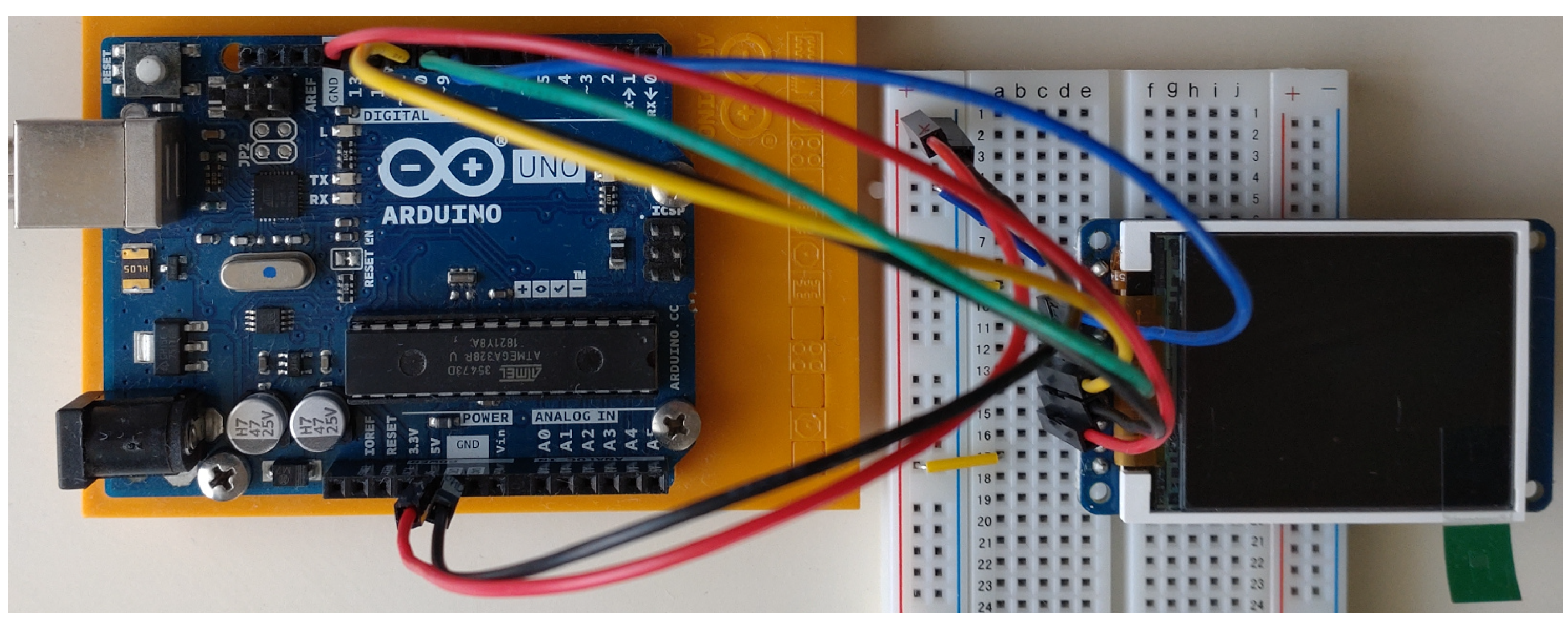
When making hardware choices, it is recalled that the adoption (popularity) of a chip is key as it directly impacts, or even conditions further developments. Effectively, a widely adopted hardware architecture enjoys multiple software libraries and peripherals. In other words, technical specifications such as the clock frequency and the amount of available memory of a chip are generally imposed by the selected ecosystem. This is why it is relevant to consider the 8-bit AVR architecture and precisely the ATmega328P chip: it equips the extremely popular microcontroller board Uno of the Arduino ecosystem, ranked no. 1 by Amazon.com in the Robotics (Industrial & Scientific) category (
https://www.amazon.com/gp/bestsellers/industrial/8498884011/, (last accessed 8 March 2022)) as of March 2022, and which “has been used in thousands of different projects and applications” to quote the official guide introduction (
https://www.arduino.cc/en/Guide/Introduction, (last accessed 8 March 2022)). Besides, the price of 8-bit AVR chips is very competitive: for example, the chip used in this research is sold for
$2.70 by the supplier (Microchip Technology, part no. ATMEGA328P-PU) and a very similar chip (same core size and speed, same program memory size, comparable connectivity and peripherals) by another manufacturer, National Semiconductor (manufacturer part no. COP8CDR9IMT7), for
$3.06 by the supplier (Rochester Electronics) at the time of writing. (Both chips are still available for purchase as of March 2022).
In addition, small size TFT-LCD panels are well adapted to minimalistic devices, such as sensors, as they are light, thin (e.g., 2.4 mm [
7]), provide high colour display—even better: an 18-bit colour depth is frequent—while limiting the required memory size, albeit with a resolution that is greatly superior to, for instance, LED matrix panels. Furthermore, they do not suffer from the lengthy display update and poor colour support of electronic papers [
5]. And obviously, TFT-LCD panels have a more flexible usage than text-only displays: they can display whatever is needed, not only characters. Finally, their cost is, as mentioned previously, generally lower than, or on a par with the aforementioned alternatives: for example,
$9.95 for a 1.8 in 18-bit colour TFT-LCD (Adafruit part no. 618 [
7]) versus
$17.50 for a 2.13 in monochrome flexible electronic paper (Adafruit part no. 4243),
$15.95 for a bicolour LED matrix (Adafruit part no. 902),
$9.95 for a monochrome 2-row 16-character text-only display (Adafruit part no. 181). (All the prices have been taken from the same vendor for fair comparison; they are as of March 2022. The price of the raw display panel was taken, when available.)
The microcontrollers that are based on the AVR instruction set architecture (ISA) have proven to be very popular for sensors and Internet of things devices. A reduced power consumption and ease of use are two important properties which can explain this trend. The AVR ISA abides by the reduced instruction set computer (RISC) architecture principles: it consists in few, simple instructions. The memory architecture of such microcontrollers is also reduced to a minimum: for example, the popular ATmega328P chip which equips many Arduino boards (Uno, Nano, etc.), only features 32 Kbytes of program memory in flash and 2048 bytes for the data memory space in SRAM. (1024 bytes of EEPROM non-volatile memory are also provided [
12]).
In this research, in order to reduce the footprint of the proposed system and the memory usage in general as much as possible, we directly rely on assembly instructions. According to the AVR ISA, data in the program memory space can be read with the LPM instruction, while the data memory space in SRAM can be accessed with the LD instruction [
13]. In this research, we rely on both of these memory spaces and thus on both of these two instructions.
These hardware characteristics demand comparable, simple I/O interfacing which accommodates itself to the extremely limited memory capacities of the MCU. The selected 1.8 in TFT-LCD panel features an 18-bit colour depth, which is common for such low-specification TFT-LCDs. In other words, the colour of one single pixel is expressed with eight bits, and there are in total
= 262,144 available colours. The resolution of the display is
pixels, with thus a total of 20,480 pixels. Hence, this display has a pixel density of
pixels per inch. The 18-bit colour mode expressing each red, green, blue (RGB) channel with one byte, an uncompressed fullscreen image requires 3 × 20,480 = 61,440 bytes, which is, as explained, problematic considering the amount of available memory. We control this display device with the serial peripheral interface (SPI) from an ATmega328P microcontroller and in accordance with the display driver (Sitronix ST7735R [
4]).
3. Methodology
The two compression techniques and, importantly, their very low-footprint implementations are described in this section. We naturally focus here on the processing done by the microcontroller; preprocessing, such as image data preparation, is only briefly presented as not directly related to our research subject.
3.1. Colour Indexing with a Palette
3.1.1. Approach Description
As explained previously, it is not possible to store fullscreen 18-bit colour image data as is directly into the program memory space (flash memory) of the MCU. So, in a first attempt at reducing the size required by the pixels, we rely on the colour indexing method: the set of colours present in the image data is reduced to a set of at most 256 distinct colours and each image pixel is mapped to the index of one palette entry. This can be done for instance with a conventional palette generation method such as that of GIMP, based on histograms [
14]. And, to visually improve the resulting image, we adjust pixels with Floyd-Steinberg dithering [
15].
Because both the palette and the indexed image data need to be stored into the program memory space of the MCU, we limit the maximum number of palette entries to 256. Each palette entry consists in three bytes, one per RGB channel, with the value
x of each RGB channel being first converted from the range
into
with the function
,
rounding to the nearest integer, and second left-shifted by two bits, so as to match the native 18-bit colour format of the TFT-LCD panel [
4]. As a result, storing the palette itself takes at most
bytes.
Moreover, thanks to this palette limitation, each pixel of the image data can be represented with one single byte—it is recalled that palette indexing is 0-base. Therefore, storing the image data after indexation requires exactly 128 × 160 = 20,480 bytes for the selected TFT-LCD panel. In total, palette and image data thus require at most 768 + 20,480 = 21,248 bytes of the program memory space. Of course, colour indexing is a lossy compression method.
3.1.2. Two Loading Techniques
Now that the image representation issue has been discussed, we describe in this section how to concretely load the compressed image data so that it is displayed on the TFT-LCD panel. We present two techniques: the first one relies solely on the program memory (flash) for the loading process, whereas the second one relies on both the program memory and the data memory in SRAM for increased performance (see below). We mention in this section only the code that is directly relevant to the image loading issue. In other words, initialization of peripherals and devices (e.g., SPI) is omitted.
After being formatted in accordance with the assembler syntax, the palette and indexed image data are included into the assembly source file with the .include directive; both are assigned a label (palette and image, respectively) for subsequent address manipulations. The main idea of the image loading algorithm is here simply to iterate each of all the palette indices that make the image data, looking up the corresponding RGB channel values inside the palette. Details are given in Listing 1.
| Listing 1. Image loading solely done with the program memory space. |
ldi r20, lo8(palette)
ldi r21, hi8(palette)
ldi r26, lo8(image)
ldi r27, hi8(image)
ldi r24, lo8(20480) ; image size
ldi r25, hi8(20480)
clr r0
data_send:
movw r30, r26
lpm r17, Z ; current pixel’s index
 ; index address in the palette
movw r30, r20
add r30, r17
adc r31, r0
add r30, r17
adc r31, r0
add r30, r17
adc r31, r0
lpm r16, Z+ ; red channel value
rcall transmit ; SPI transmission
lpm r16, Z+ ; green channel value
rcall transmit
lpm r16, Z ; blue channel value
rcall transmit
adiw r26, 1 ; next pixel
sbiw r24, 1 ; decrement counter
brne data_send
|
Because loading directly from the program memory in flash takes one more cycle than loading from the data memory space in SRAM (the LPM instruction requires 3 cycles against only 2 for the LD instruction), copying the entire palette to the data memory space in SRAM before doing lookups is a possible optimisation since a palette entry is likely to be accessed more than once: the probability that a same index is used multiple times inside the image data is high. So, the loading code can be refined as shown in Listing 2; it is key to notice therein that the transfer of the red, green, blue channel values to the display are now done with the LD instruction instead of the LPM instruction as done in Listing 1. Besides, this optimisation requires the number of palette entries to be known; it is stored as prefix to the palette.
| Listing 2.Image loading done with both the program memory space (flash) and the data memory space (SRAM). |
ldi r26, lo8(SRAM) ; data space addr.
ldi r27, hi8(SRAM)
ldi r30, lo8(palette)
ldi r31, hi8(palette)
lpm r1, Z+
mov r24, r1 ; palette size calcul.
clr r25
adiw r24, 1
clr r0
add r24, r1
adc r25, r0
add r24, r1
adc r25, r0
copy: ; one channel at a time
lpm r16, Z+ ; load from flash
st X+, r16 ; copy into SRAM
sbiw r24, 1 ; decrement counter
brne copy
ldi r30, lo8(image)
ldi r31, hi8(image)
ldi r24, lo8(20480)
ldi r25, hi8(20480)
ldi r26, lo8(SRAM)
ldi r27, hi8(SRAM)
clr r0
data_send:
lpm r17, Z+ ; current pixel’s index
movw r28, r26 ; index address calcul.
add r28, r17
adc r29, r0
add r28, r17
adc r29, r0
add r28, r17
adc r29, r0
ld r16, Y+ ; red channel value
rcall transmit ; SPI transmission
ld r16, Y+ ; green channel value
rcall transmit
ld r16, Y ; blue channel value
rcall transmit
sbiw r24, 1 ; decrement counter
brne data_send
|
3.2. Run-Length Encoding
Compression with colour indexing as presented and implemented earlier is a first step to reduce the size of the image data. As a second, complementary step, we rely on run-length encoding (RLE), which is this time a lossless compression method (refer, for instance, to the T.45 recommendation [
16] for a sample application). The principle of this compression method is to represent a sequence of consecutive same values as a
pair with
the number of times
appears in the sequence. Hence, the size of the compression result greatly varies depending on the structure of the data: the more the consecutive same values, the smaller the result size.
Considering the severe memory restriction faced as mentioned previously, not only needs the size of the image data to be appropriately reduced, but the size of the machine code required to process such data also needs to be minimal in order to leave enough program memory available for the rest of the microcontroller program. Hence, when selecting a compression algorithm, its ease of implementation and simplicity in general are critical. Besides, although not as critical as the memory issue, the processing performance of the chip has to be taken into account: decompression of image data is expected to be fast in order to retain practicability. For these reasons, RLE compression is a meaningful solution, and this is why it is frequently used in such minimalistic environments (e.g., sensors) [
17]. Finally, even if an RLE compression technique is suboptimal when dealing with images including many colours and thus few consecutive pixels of the same colour, the fact that we combine this compression method together with colour indexing with a palette, thus effectively reducing the number of colours throughout the image data and consequently increasing the probability of consecutive pixels of a same colour, induces the relevance of our approach even in this particular situation.
So, we rely on this principle and adapt it to the MCU architecture so as to optimise the results. Just as we restricted the number of palette entries to 256 in order to be able to express image data with single byte palette indices, we limit the length of a sequence of consecutive same pixel values (i.e., palette indices) to 255, that is, , so as to use one single byte to iterate. Therefore, if there is a sequence of more than 255 consecutive same values, several pairs are generated. Precisely, a sequence of x consecutive same values v induces pairs of the form followed by one pair of the form where , if . The total number of such pairs is needed to process the image data, and thus added as prefix to them.
Not only can this second compression method drastically reduce the program memory required, it can also accordingly reduce the number of program memory read operations (LPM instruction), which is, we recall, a heavier operation (3 cycles) than usual ones (1 cycle). This is important for parallelisation with pipelining as provided by the MCU. Precisely, instead of executing n () program memory read operations with the LPM instruction, we execute one read operation to retrieve and another one for , here a palette index.
For the sake of conciseness, the assembly source of this second method is omitted. Of course, the two loading methods described previously and detailed in Listings 1 and 2 are applicable. The main difference when implementing the RLE compression method we have just described is that image data consist of count–index pairs, so, for each such pair, and are read from the program memory, is looked up in the palette as before and the corresponding RGB channel values are repeatedly transmitted times.
5. Discussion
5.1. General Discussion of the Obtained Results
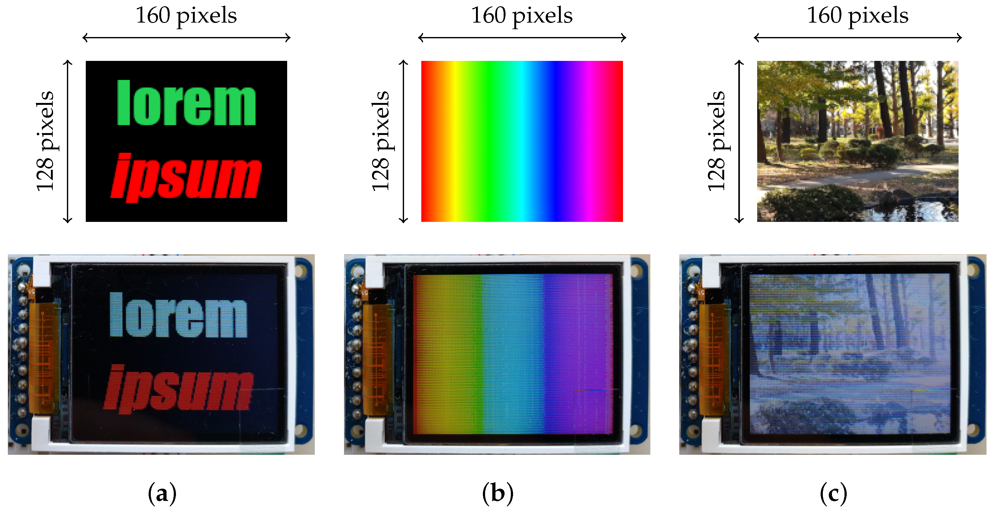
First, we discuss the obtained qualitative results (renderings): the images were all instantly loaded and rendered successfully on the TFT-LCD panel. Besides, there are no apparent graphical artefacts or glitches other than the inevitable minor ones induced by colour indexing compression. Image 1 induces a colour palette of 223 entries (text anti-aliasing produces many colours) and Images 2 and 3 a full colour palette of 256 entries. The quality of the renderings, for instance the visible horizontal lines, matches the hardware specifications of the TFT-LCD panel used for this experiment and are thus unrelated to the proposed methodology. The reduction of the number of colours is most visible with the rendering of the colour spectrum of Image 2 (
Figure 2b); it is characteristic of colour spectra since they consist of colour gradients.
While the run-length encoding compression method has been applied to binary (monochrome) images [
19], we have selected this algorithm for its performance, simplicity and lossless properties. It has also enabled us to increase parallelization by reducing the number of multi-cycles instructions (LPM, precisely), which is discussed in [
20] but again for binary images.
The feasibility of the proposal has been successfully shown given that image data are successfully loaded and displayed. The practicability of the proposal has also been shown: program memory remains available, it is not fully used. Of course, this depends on the loaded image, but in the worst case (palette only, no RLE compression) 1 + 256 × 3 bytes are required for the palette, 20,480 × 1 bytes for the image data, plus the machine code that corresponds to the loading code—here we take the loading method that is based on the program memory & SRAM combination since we are considering the worst case—for a grand total of 21,438 bytes. Hence, since 32 Kbytes of program memory are available, approximately 33% remain available for other instructions.
Without compression, 20,480 × 3 = 61,440 bytes are required to represent a fullscreen image in this 18-bit colour mode, which is thus impossible to store directly into the microcontroller as explained. The results show that the proposal is able to significantly reduce the size required to represent such an image.
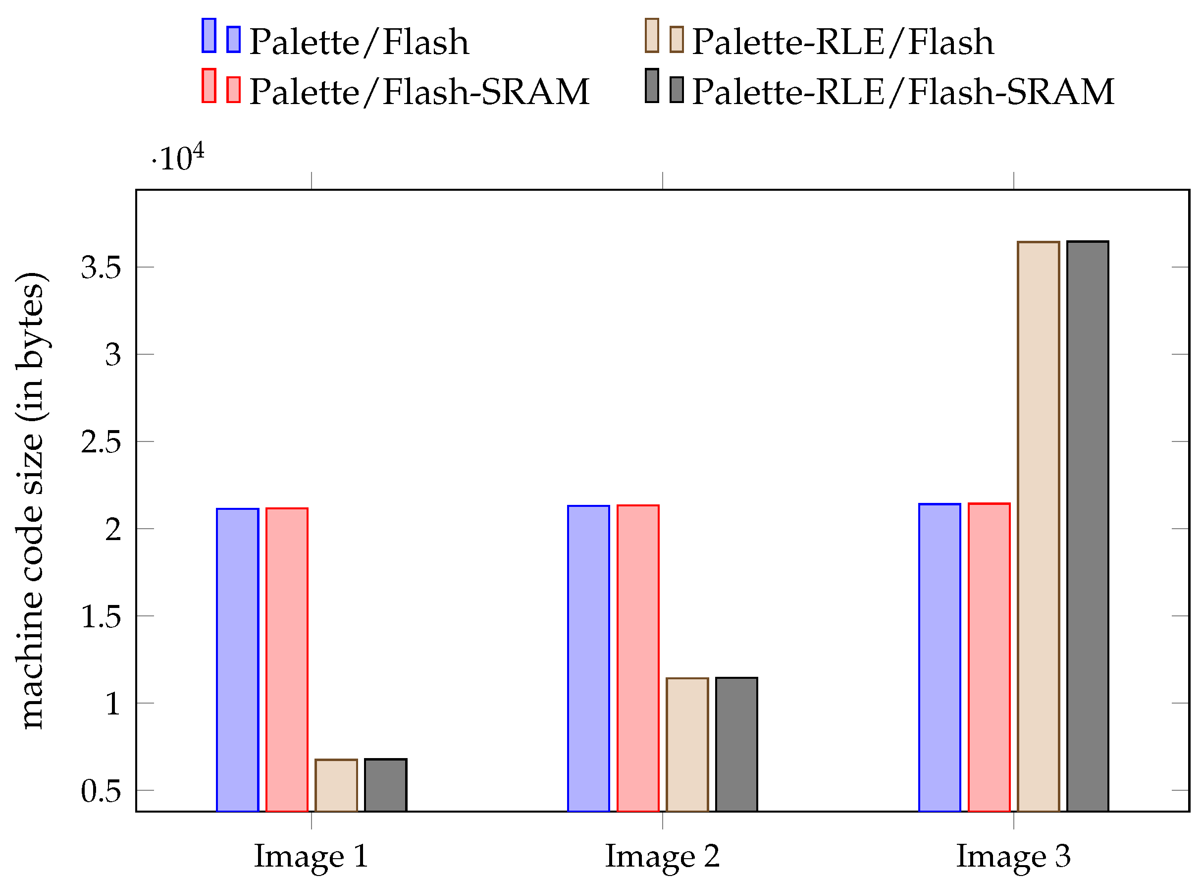
Depending on the image data, RLE compression can adversely affect the required memory size (i.e., a larger size than the original image data), and that even if RLE is applied to image data that have been compressed beforehand with colour indexing as in our proposal. This is precisely the case for Image 3 as shown in
Figure 3; the size of the produced machine code exceeds the available amount of program memory and cannot thus be uploaded to the ATmega328P microcontroller. The worst case of such a scenario is when the image has no two consecutive pixels of the same colour.
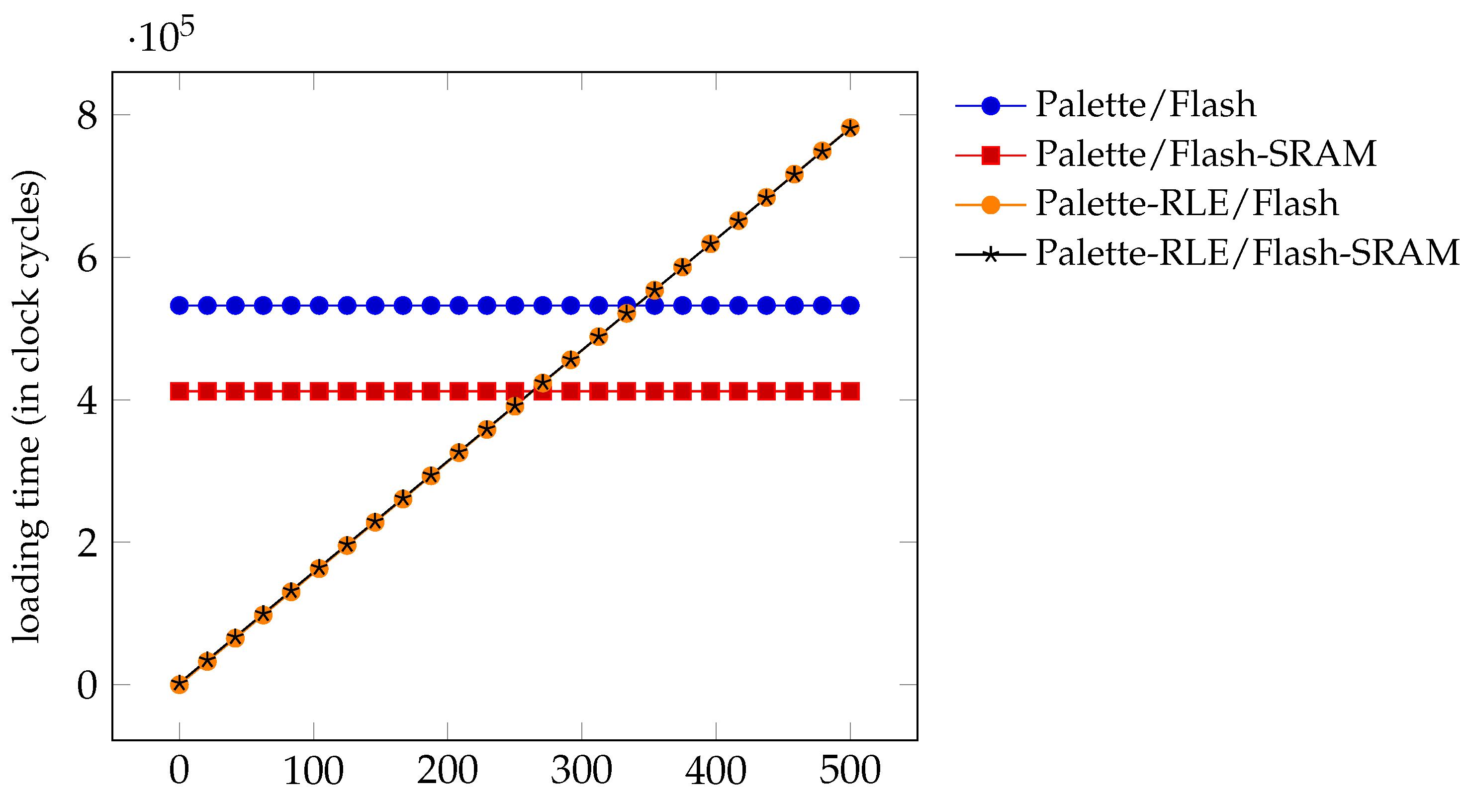
Regarding the loading time results, they exhibit an optimal time complexity, that is, a time complexity which is linear in the size of the input data (i.e., the image data). It is recalled that these results are an upper bound on the loading time: this time is reduced for images that induce smaller colour palettes.
5.2. Comparison with Related Works
Finally, we conclude this discussion section by further showing the contribution of the proposal by comparing it to related works. First, with the Adafruit GFX Library by Phillip Burgess [
21], it is not possible to load such images, only monochrome bitmaps (e.g., in the XBM format)—see the
drawBitmap function and its variants. (Coloured bitmap files could be loaded with this library from an SD card.)
Second, we consider the RLEbitmap library by Michael Hotchin [
22]. To start, it should be noted that due to its low-level memory management calls (e.g.,
pgm_read_byte_far), the RLEbitmap library is simply not usable for a low-memory microcontroller such as the ATmega328P—errors are produced when attempting to compile the image loading program. It is instead required to select a chip such as the ATmega2560, and this is yet another severe limitation compared to our proposal. Nonetheless, we specify an ATmega2560 chip to the library to further investigate.
We reuse the exact same three sample images (Images 1, 2 and 3 of
Section 4) for fair comparison. These images are saved in the BMP format (uncompressed format) as required by RLEbitmap and converted to a bit map in C++ code (a byte array, precisely) by the utility provided with RLEbitmap (
bmper). Then, the corresponding machine code for the MCU which simply displays the image on the TFT-LCD has been conventionally built with the Arduino development environment with ATmega2560 as build target. It should be noted that, as specified by RLEbitmap, the Adafruit GFX Library and Adafruit ST7735 and ST7789 Library are loaded to generate the machine code.
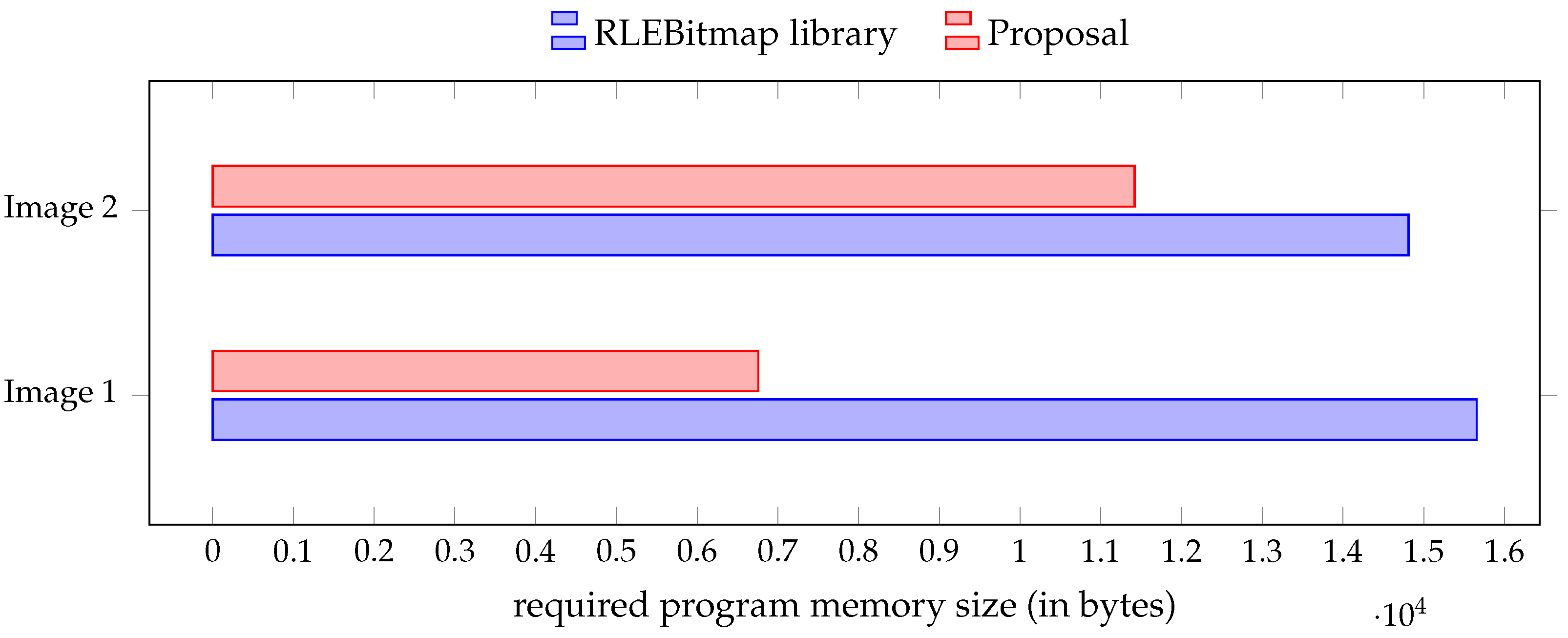
First, it is essential to note that the RLEBitmap library generates significantly larger machine code than our method: +132% in the case of Image 1 and +30% in the case of Image 2, approximately. The required size of the program memory space is calculated just as it was for the results of
Section 4, with
avr-size. Second, the RLEBitmap library simply fails at producing any machine code in the case of Image 3 due to the large size of this image. This library is thus again superseded by our proposal. The obtained results with respect to the machine code size, that is, the required amount of program memory, are summarised and compared with our proposal in
Figure 5.
6. Conclusions
The minimalistic hardware of most IoT devices and sensors, especially those based on microcontrollers, induces severe restrictions on their storage capacity and interfacing capabilities. Nonetheless, there exist many applications that demand not only textual but also graphical display features. The storage of fullscreen data is thus highly problematic and existing solutions have even resorted to requiring external storage (e.g., a microSD card) for that purpose. In this paper, we have described two very low-footprint solutions to enable this scenario without having to rely on additional hardware. These two solutions can be combined for improved results. The proposal has been qualitatively and quantitatively evaluated, and the obtained results have been discussed. Simply stated, we have shown that what was previously impossible is now not only feasible but also practical, and can pave the way for significant cost reductions.
Regarding future works, conducting experiments with additional sample images to further generalise the obtained results is one possibility. Although it might be interesting to consider other compression algorithms, one merit of our approach is its simplicity, necessary for microcontroller architectures, and short implementation, necessary given tight storage limitations. In any case, investigating integration means of the proposal into existing applications is a meaningful objective. Finally, although devices based on the ARM architecture include generally larger memory spaces, some like the Arduino MKR Zero and the Raspberry Pi Pico still face severe memory restrictions. Considering the ARM architecture instead of AVR is thus yet another possible future research direction.


