Article

Processing of Aluminum Alloy 6182 with High Scanning Speed in LPBF by In-Situ Alloying with Zr and Ti Powder

by
Kirstin Riener
1,2,*,
Alexander Nagler
1,
Ilse Letofsky-Papst
3 and
Gerhard Leichtfried
2
1
BMW Group FIZ, Knorrstraße 147, 80788 Munich, Germany
2
Department of Mechatronics, Materials Science, Faculty of Engineering Sciences, University of Innsbruck, Technikerstrasse 13, 6020 Innsbruck, Austria
3
Institute for Electron Microscopy and Nanoanalysis and Center for Electron Microscopy, Graz University of Technology, NAWI Graz, Steyrergasse 17, 8010 Graz, Austria
*
Author to whom correspondence should be addressed.
Alloys 2022, 1(3), 277-287; https://doi.org/10.3390/alloys1030018
Submission received: 4 November 2022 / Revised: 28 November 2022 / Accepted: 30 November 2022 / Published: 8 December 2022
(This article belongs to the Special Issue Design of New Metallic Alloys for AM)

Abstract

:
The demand for high-strength aluminum alloys for the laser powder bed fusion (LPBF) process is still growing. However, to date, the crack susceptibility of conventional alloys as well as the high prices for specially developed alloys are the main obstacles for the use of high-strength aluminum alloys for LPBF. In this paper, crack-free LPBF samples with a relative density >99.9% were processed from AlMgSi1Zr (6182 series alloy) powder, to which 0.5 wt.-% Zr and 0.5 wt.-% Ti were added via mechanical mixing. No hot cracks were found in the µCT scans. Moreover, a fully equiaxed microstructure with a mean size of the α-Al grains of 1.2 µm was observed in the as-built parts. Al3(Zr,Ti) particles were observed, acting as efficient heterogeneous grain refiners for α-Al by building a semi-coherent interface. Unmolten Ti and Zr particles with sizes up to 80 µm were found in the α-Al phase. The resulting fine-grained microstructure led to a tensile strength of 329 ± 4 MPa and a total elongation at a break of 11.4 ± 0.9% after solution heat treatment, quenching in water, and subsequent artificial ageing.

1. Introduction

LPBF, or selective laser melting (SLM), is, to date, the most important technology for the additive manufacturing (AM) of metals [1]. These emerging technologies have the potential to revolutionize global part manufacturing because they provide new opportunities in tool-less production [2] and the structural optimization of lightweight parts [3].
Not least because of their widespread application in aerospace and automotive industry, the processing of aluminum cast alloys via LPBF has been extensively studied in recent years [4], focusing on the laser-related process parameters [5], the build platform temperature [6], the resulting microstructure [7] as well as the accompanying mechanical properties. Moreover, the appropriate handling of Al-Si based cast alloys is well understood [8]. Therefore, they can be successfully manufactured into fully dense and crack-free LPBF parts [9]. However, high-strength aluminum-wrought alloys from the 2xxx, 5xxx, 6xxx and 7xxx series are more challenging to process via LPBF [10]. Bad fluidity and high solidification rates lead to a columnar microstructure with a high number of hot cracks [11]. Recent studies have shown that this issue can either be resolved by adjusting the chemical composition of the material by adding Si [12,13], Sc [14,15], and Zr [12,15] and/or secondary particles such as TiB2 [13,16] in order to gain a grain-refining effect [17,18]. A further approach to completely suppress hot cracking is to elevate the substrate plate temperature up to 500 °C. Thereby, on the one hand, the reduced solidification rate due to the lower temperature difference between the melt pool and the surrounding material leads to an improved filling of the interdendritic spaces and thus to a reduction in hot cracks. On the other hand, a fine-grained, equiaxed microstructure is formed because of the modified solidification conditions, which is known to have a positive influence on the prevention of hot cracks [19].
Nevertheless, all these tailored alloys still face major obstacles hindering their broad application in the automotive industry. The main issues are the use of rare earth elements like Scandium [14] and patents with accompanying high prices [20] and only single sourcing options [21] for the material and/or the equipment [22]. Moreover, adverse chemical compositions, such as high Mg/Si-ratios [23] or Zn [24] and Cu-containing base materials (or a combination of that [25,26], can lead to intergranular [27] or pitting [28] corrosion in the LPBF parts. To prevent the outlined problems, it would be favorable to consider high-strength aluminum alloys which are already used in conventional manufacturing processes, such as extruding or die-forging, for the LPBF process.
In the present paper, Zr and Ti were used as efficient and economically interesting grain refiners for enabling LPBF of high-strength aluminum parts. The aluminum alloy 6182 was chosen as a base material as it is one of the few materials showing good weldability and corrosion resistance in combination with a high strength. Because of the before mentioned properties of the 6182 material, the 6082 alloy with nearly identical chemical composition is a widely used material in the automotive industry. The objective was to achieve crack-free and high-strength aluminum parts with good elongation processed by LPBF. In addition to the mechanical characterization regarding hardness and tensile properties, especially the microstructure was thoroughly analyzed using µCT, EBSD, and TEM.

2. Material and Methods

2.1. Materials and Processing

Two different aluminum alloy compositions were manufactured via LPBF. The 6182 powder was produced by inert gas atomization (IMR Metal Powder Technologies GmbH, Velden am Wörthersee, Austria). To suppress hot cracking in the LPBF process, the 6182 powder was pre-alloyed with 0.2 wt.-% of each Zr and Ti. To manufacture crack-free LPBF parts, additional 0.5 wt.-% of each gas atomized Zr and Ti powders (TLS Technik GmbH & Co. Spezialpulver KG, Niedernberg, Germany) were added to the 6182 pre-alloyed powder by mechanical mixing. A TURBULA® T2F 3D shaker from Willy A. Bachofen AG (Muttenz, Switzerland) was used for this purpose.
The chemical compositions of the 6182 powder and of the powder mixture were analyzed by inductively coupled plasma optical emission spectrometry (ICP-OES) according to DIN EN 12424, using a 5100 ICP-OES from Agilent Technologies, Inc (Santa Clara, USA). The results can be seen in Table 1.
To obtain a visual overview of the shape and surface morphology of the powder particles, a scanning electron microscope Cross Beam 1540Esb (Carl Zeiss Microscopy Deutschland GmbH, Oberkochen, Germany) was used. It revealed a mostly spherical particle shape for all powders. In contrast to the pre-alloyed powder particles (Figure 1a,b), which exhibit a smooth surface, both the Ti and Zr powder that were used for alloying show some satellite attachments on the particles surface (Figure 1c–f).
The particle size distributions (PSD) of the powders were determined with a Camsizer X2 from Microtrac Retsch GmbH (Haan, Germany), using dynamic image analysis according to ISO 13322. The results are shown in Table 2.
All specimens for the characterization of the LPBF part properties were produced on a customized AconityONE LPBF machine from Aconity3D GmbH (Herzogenrath, Germany). Nitrogen was used as shielding gas. A parameter optimization of the final mixed powder resulted in the process parameter set shown in Table 3.
Cuboids with a dimension of 10 × 10 × 16 mm3 (for light microscopy, SEM, EBSD, TEM) and 5 × 5 × 16 mm3 (for µCT), as well as cylinders with a geometry of Ø 8 mm × 100 mm were built using the process parameters mentioned in Table 3. The cylinders were then machined into tensile test specimens with the geometry B5 × 26 according to DIN 50125. The specimens for the tensile test were built at a 45° angle to the build platform.
To increase the mechanical strength of the LPBF parts, a T6-like heat treatment according to ISO 2107 was performed on one cuboid for hardness measurement and six cylinders for tensile testing with the following parameters: solution heat treatment at 520 °C for 60 min, quenching in water, and subsequent ageing at 165 °C for 8 h. Here, it is important to point out that only the subsequent ageing time was optimized for the modified 6182 alloy. All other heat treatment parameters (solution heat treatment time and temperature, ageing temperature) were adopted from our T6 heat treatment for AlSi10Mg LPBF parts.

2.2. Characterization of the LPBF Parts

The density of the LPBF parts was optically measured on ground and polished cross-sections of the cuboids. Therefore, a light microscope Axio Imager M2m equipped with an AxioCam MRc (both Carl Zeiss AG, Jena, Germany) was used for taking images from the entire cross-section of the cuboids after grinding and polishing. Afterwards, these images were processed with the software Imagic IMS to separate voids from the solidified material by applying a grey-value threshold. The relative density was then determined by the quotient of the area of the solidified material and the area of the analyzed cross section. To form the arithmetic mean with the associated standard deviation, three cubes were considered. To investigate the hot-crack susceptibility of the LPBF parts, µCT were performed on a Phoenix v|tome|× 240 from General Electric, using an acceleration voltage of 120 kV.
For characterization of the microstructure, a scanning electron microscope Helios NanoLab 600i FIB (FEI Company, Hillsboro, USA) was used, equipped with an energy dispersive X-ray spectroscopy (EDX) system and an electron backscatter diffraction (EBSD) system.
High-resolution STEM images were obtained from a FEI Titan G3 60–300, using a beam voltage of 300 kV. The advanced instrumentation installed on this microscope enables to record HR-STEM images with annular dark field (ADF), annular bright field (ABF), and high angle annular dark field (HAADF) detectors. The chemical composition of the different phases was detected by energy dispersive X-ray (EDX) analysis. For this purpose, the microscope was equipped with an FEI Super-X windowless silicon drift detector (Chemi-STEM technology). The electron-transparent specimen was taken from the central area of a parameter-optimized 10 × 10 × 16-mm3 specimen and was prepared under cryogenic conditions using the Pips II from Gatan (Gatan Inc., Pleasanton, USA).
The tensile tests were performed on six specimens according to DIN EN ISO 6892 using a Z020 Allroundline testing machine from ZwickRoell GmbH & Co. KG (Ulm, Germany). Vickers hardness was measured in accordance with DIN EN ISO 6507 using an EMCO Test M1C010 (EMCO-TEST Prüfmaschinen GmbH, Kuchl, Austria). Five measurements were carried out. The respective mean values and standard deviations were calculated for all mechanical tests.

3. Results and Discussion

3.1. Status Quo: Microstructural Analysis of the Printed Parts Manufactured with Pre-Alloyed 6182 Powder

The µCT scan shown in Figure 2 displays the longitudinal and horizontal cross-sections of a LBPF specimen manufactured using pre-alloyed 6182 powder and the process parameters that are shown in Table 3. The entire specimen is permeated with hot cracks and reveals pores that are mainly located at the edge, which can be explained by the fact that no contour parameters were used. Due to this, heat accumulation occurs at the edge of the specimen, which favors the formation of pores. Leaving this porous area disregarded, an average part density of 99.95 ± 0.05% can be achieved.
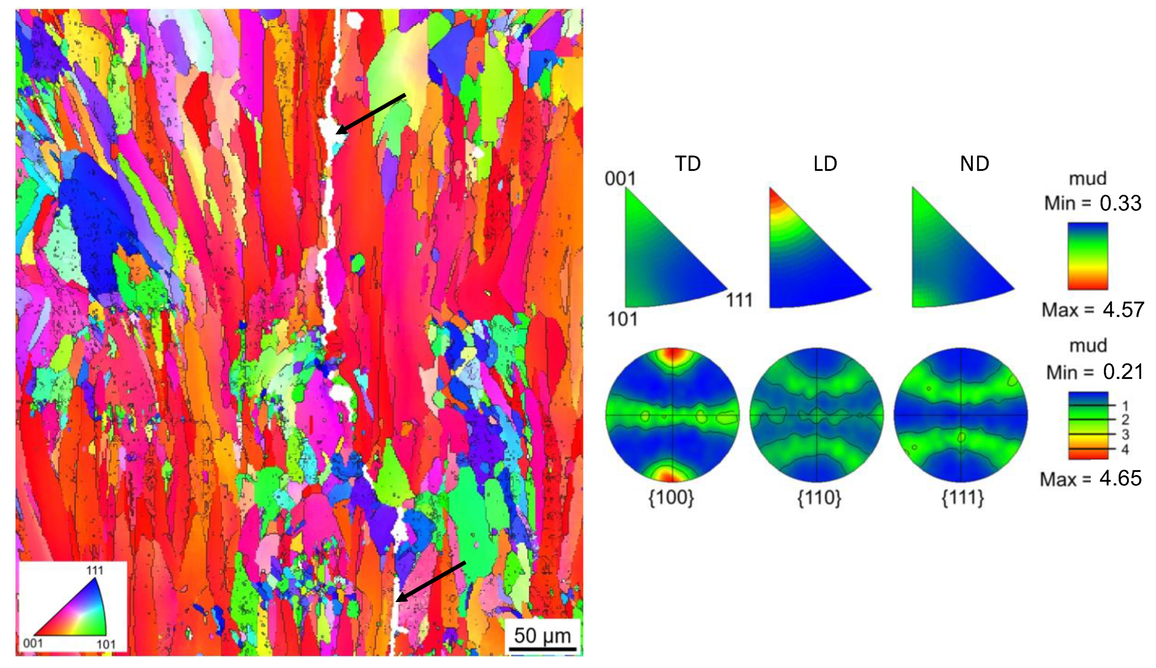
The EBSD micrograph (Figure 3 EBSD micrograph in the longitudinal direction (or building direction) and inverse pole figures of the Figure 3, left) reveals mostly columnar grains which are elongated along the building direction (LD). An orientation of the grains in the [001] direction dominates, which is also shown in the inverse pole figures (Figure 3, right). The [001] direction is the preferred growth direction in the fcc crystal system and dominates in the building direction because of the heat flow that is directed against the building direction [19]. Due to the expansion of the grains over several layer thicknesses (50 µm), epitaxial grain growth can be assumed.

3.2. Characterization of the Printed Parts, Manufactured with the Powder Mixture

The specimens produced with optimized process parameters (Table 3) reveal an average part density of 99.95 ± 0.05%.
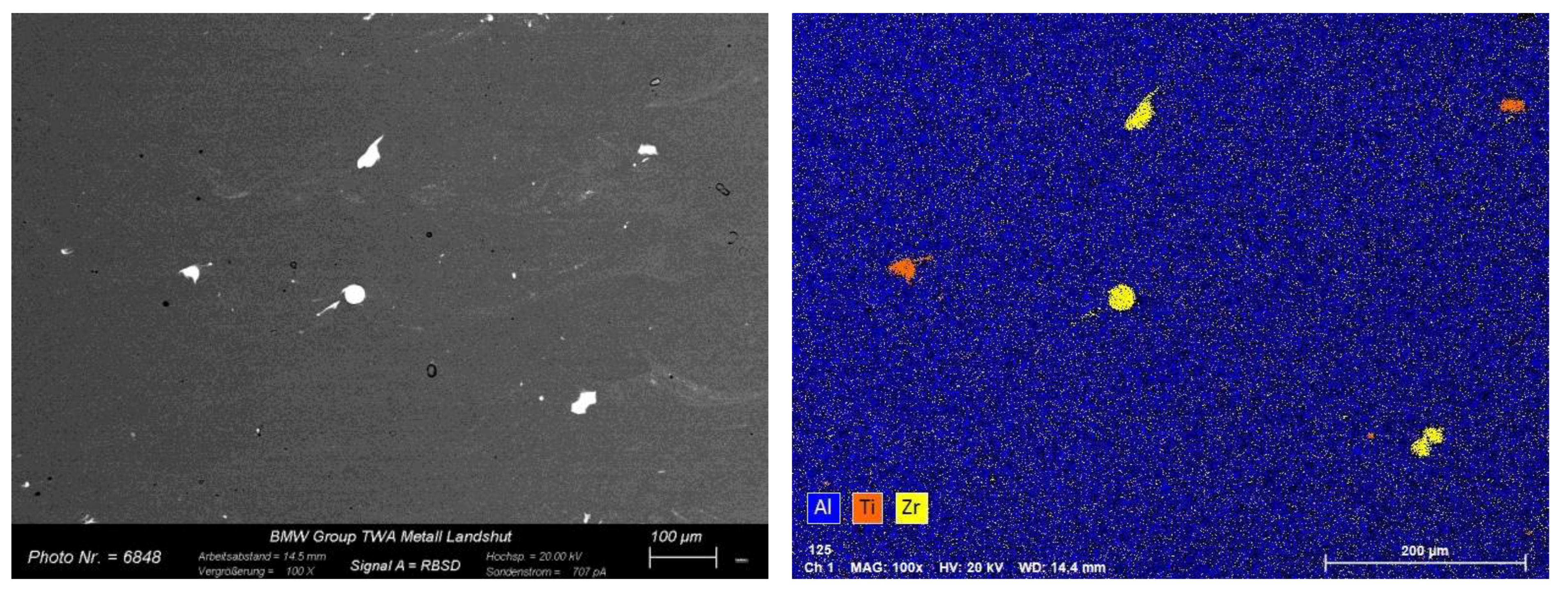
Figure 4 illustrates the µCT scan of the as-built LPBF specimen. No hot cracks can be observed. The pores are located at the edge, which can be again explained by the fact that no contour parameters were used. The white dots can be referred to unmolten or only partially molten Zr and Ti particles (compare Figure 5).
Figure 5 displays the above mentioned unmolten or only partially molten Zr and Ti particles. The reason for the occurrence of unmelted particles could be that these particles are transported by the gas convection into a cooling melt pool, the energy of which is not sufficient to completely melt the higher melting Ti or Zr particles.
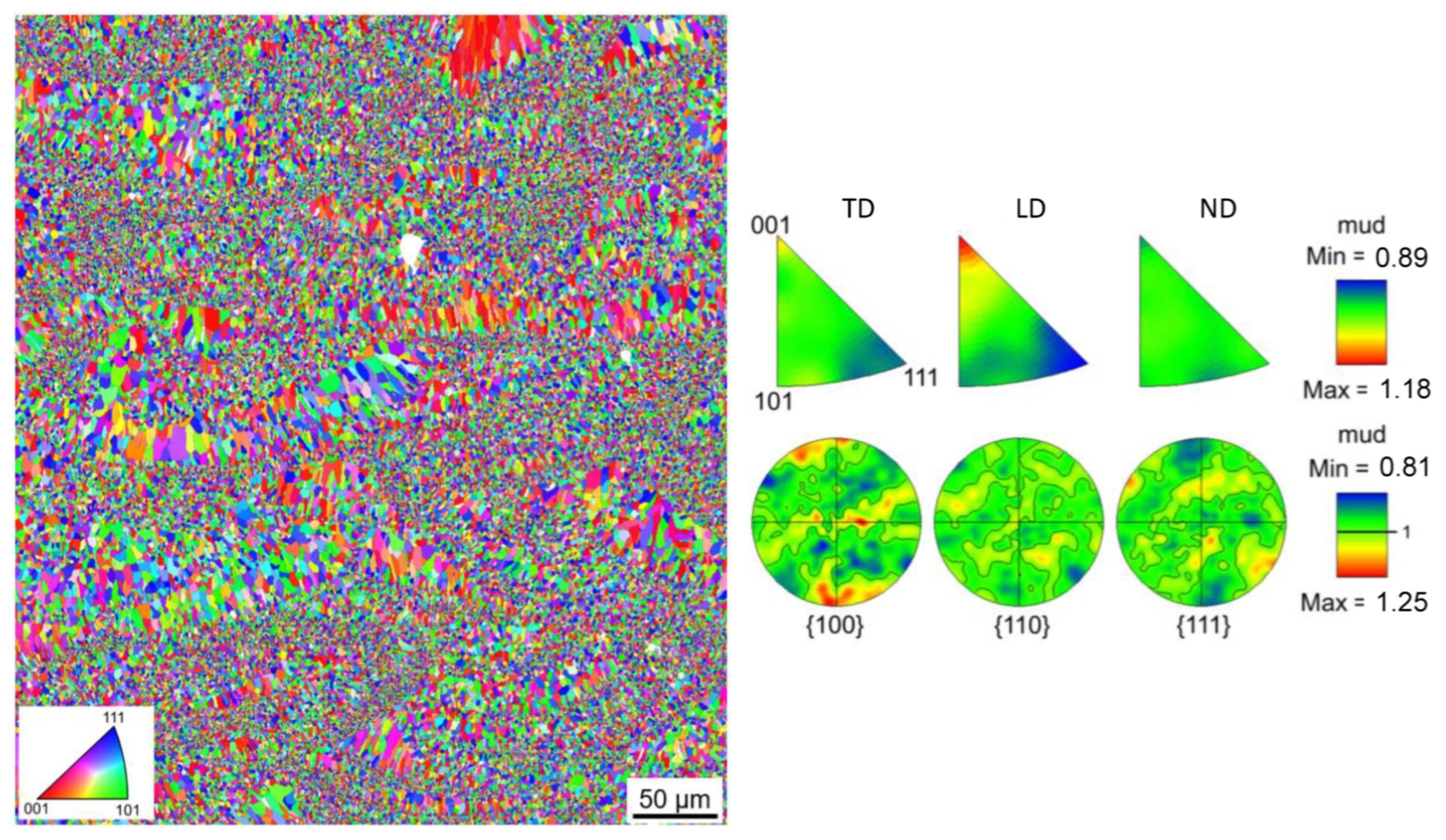
The EBSD micrograph and the inverse pole figures (Figure 6) reveal a mostly equiaxed, fine-grained microstructure (average grain size is 1.2 µm) without a pronounced crystallographic texture. These changes in microstructure can be referred to the grain refining effect of the added Zr and Ti.
Microstructural characterization in TEM was performed on parts in the as-built status to characterize the phase distribution. Figure 7a shows a HAADF-STEM micrograph of the fine grained, equiaxed α-Al grain area, and Figure 7b presents the corresponding energy-dispersive X-ray spectroscopy (EDX) maps for Al, Mg, Fe, Ti, O, Si, Mn, Zr. The different phases occur primarily at the grain boundaries. Figure 7b reveals different types of intermetallic phases. The Al free phases contain only Mg and Si. It can be assumed that these are the Mg2Si phases that are well known from the 6000 series alloy. The Mg2Si phases visible in this magnification level were either formed as primary phases during solidification or have been precipitated over the long process time due to the elevated build plate temperature. The hardening effect of these phases, which are coarsely present in the as-built state, can be expected as rather low. The second type of precipitates contain the element combination of Fe and Mn. In addition, Al and Si are present in this phase, so they can be assigned to the Al(Fe,Mn)Si phases that usually precipitate in 6000 series alloys. The alloyed Ti and Zr can be detected both dissolved in the Al matrix and in precipitates. It is noticeable that Ti and Zr tend to occur together.
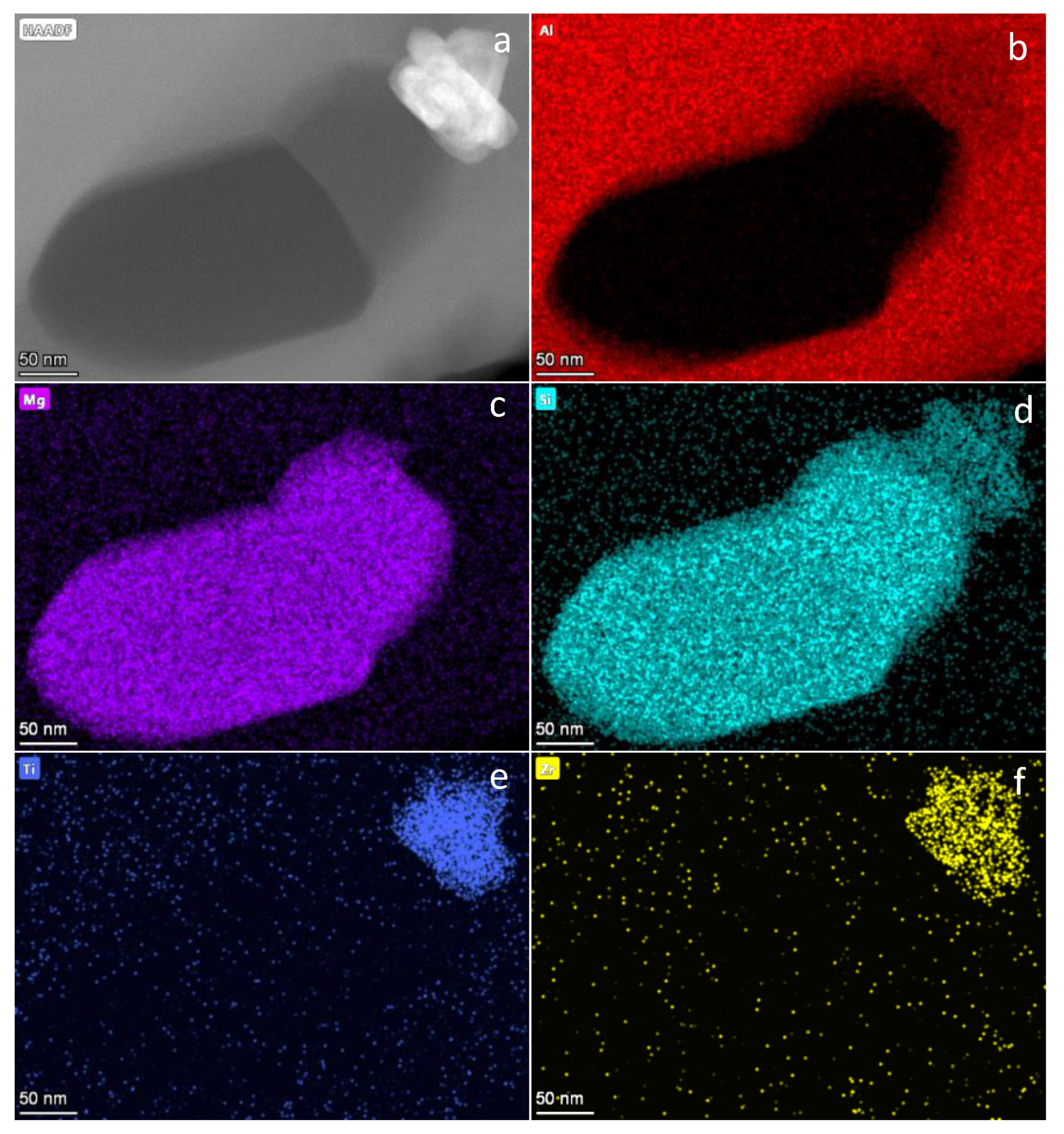
Figure 8 shows the HAADF-STEM micrograph and EDX maps of a Ti- and Zr-containing precipitate within an α-Al grain, as well as an adjacent Mg- and Si-rich precipitate, which could be clearly assigned to a Mg2Si phase in further analysis. Si and Al are also enriched in the region of the Ti- and Zr-containing phase.
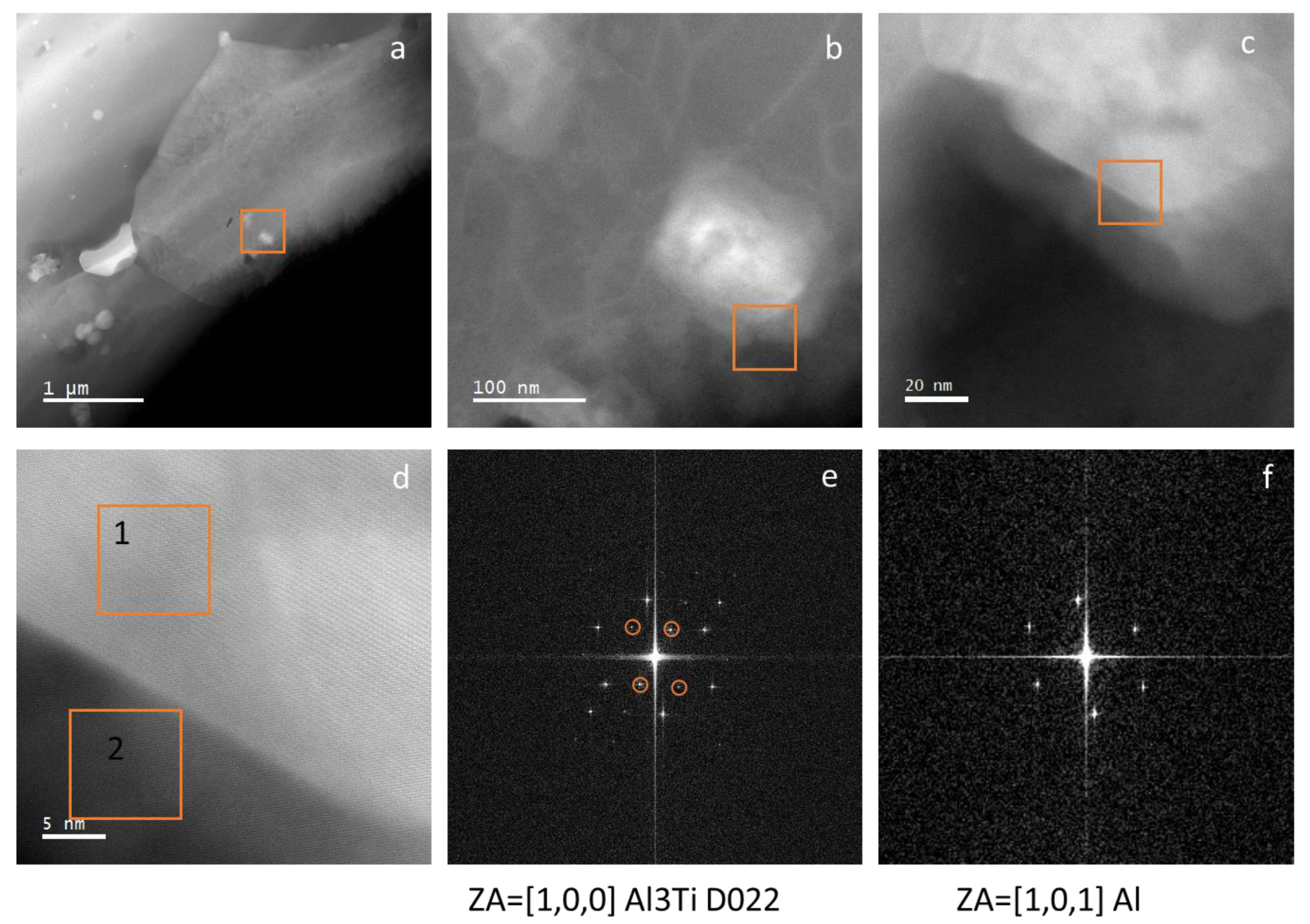
Figure 9 illustrates a (HAADF)-STEM overview image showing precipitates within an α-Al grain. At higher magnification levels (Figure 9b–d), an α-Al-Al3Ti interface can be seen. Figure 9d, a high-resolution section of the area marked with an orange rectangle in Figure 9c, allows calculation of fast Fourier transforms (FFTs) and determination of orientation relationship. The FFTs reveal that these precipitates are the orthorhombic D022-Al3(Ti,Zr) phase. The interface between particle and matrix is coherent in the orientation shown, as the D022 phase co-shares at least one crystal plane with the α-Al matrix. Thus, a nucleation effect of the Ti- and Zr-containing phases on the Al matrix can be assumed. As already displayed in Figure 8, the trialuminides Al3(Ti,Zr) can be surrounded by the Al(Fe,Mn)Si and Mg2Si particles. It can be assumed that Al(Fe, Mn)Si and Mg2Si phases preferentially form on each other or on trialuminides.
The mechanical properties of the LPBF specimens in as-built and T6 condition are illustrated in Table 4. Here, the mean values and standard deviations of hardness, yield strength, ultimate tensile strength, and elongation at break can be compared. In order to surpass the mechanical properties of AlSi10Mg and to reach the values of wrought aluminum 6182 in T6 state, T6 heat treatment is also necessary for the LPBF specimens. The increase in strength after T6 heat treatment can be attributed to precipitation hardening of Mg- and Si-rich phases, as it is already well studied for AlMgSi-alloys [29]. Since most of the heat treatment parameters have been adopted from a T6 heat treatment for AlSi10Mg LPBF parts, it might be possible to further enhance the mechanical strength by adjusting the heat treatment.

4. Conclusions

In the present work, a 6182 series alloy was modified using Zr and Ti and processed via LPBF. The key findings of the study can be summarized as follows:
  • LPBF parts made of pre-alloyed 6182 powder (with 0.2 wt.-% each of Zr and Ti) reveals a columnar, epitaxially grown grain structure permeated with hot cracks;
  • The powder mixture containing 0.7 wt.-% each of Zr and Ti was processed using LPBF. A crack-free microstructure was achieved, showing a relative density of 99.95 ± 0.05%;
  • Unmolten or only partially molten Zr and Ti particles remain in the microstructure;
  • An equiaxed microstructure with a grain size of 1.2 µm on the average was obtained in the as-built specimen;
  • Orthorhombic D022 Al3(Ti,Zr) particles work effectively as an heterogeneous grain refiner for α-Al, evidenced by the coherent interface that was found between D022 particles and α-Al;
  • In the as-built condition, the material exhibits an average yield strength of 155 ± 5 MPa with an elongation at break of 25.1 ± 1.8 %. After T6 heat treatment, an average yield strength of 294 ± 2 MPa with an elongation at break of 11.4 ± 0.9 % can be achieved.

Author Contributions

Conceptualization, K.R.; Methodology, K.R.; Formal Analysis, K.R., A.N. and I.L.-P.; Investigation, K.R., A.N. and I.L.-P.; Resources, K.R.; Data Curation, A.N. and I.L.-P.; Writing—Original Draft Preparation, K.R and I.L.-P.; Writing—Revised Version, K.R.; Visualization, K.R., A.N. and I.L.-P.; Supervision, G.L. All authors have read and agreed to the published version of the manuscript.

Funding

This research received no external funding.

Data Availability Statement

All data will be made available upon request.

Acknowledgments

The authors would like to thank all involved colleagues from the BMW lab who assisted in investigation.

Conflicts of Interest

The authors declare no conflict of interest.

References

  1. Frazier, W.E. Metal Additive Manufacturing: A Review. J. Mater. Eng. Perform. 2014, 23, 1917–1928. [Google Scholar] [CrossRef]
  2. Ngo, T.D.; Kashani, A.; Imbalzano, G.; Nguyen, K.T.; Hui, D. Additive manufacturing (3D printing): A review of materials, methods, applications and challenges. Compos. Part B Eng. 2018, 143, 172–196. [Google Scholar] [CrossRef]
  3. Poprawe, R.; Hinke, C.; Meiners, W.; Schrage, J.; Bremen, S.; Risse, J.; Merkt, S. Disruptive Innovation Through 3D Printing. In Supply Chain Integration Challenges in Commercial Aerospace; Richter, K., Walther, J., Eds.; Springer International Publishing: Cham, Switzerland, 2017; pp. 73–87. [Google Scholar]
  4. Zhang, J.; Song, B.; Wei, Q.; Bourell, D.; Shi, Y. A review of selective laser melting of aluminum alloys: Processing, microstructure, property and developing trends. J. Mater. Sci. Technol. 2019, 35, 270–284. [Google Scholar] [CrossRef]
  5. Trevisan, F.; Calignano, F.; Lorusso, M.; Pakkanen, J.; Aversa, A.; Ambrosio, E.P.; Lombardi, M.; Fino, P.; Manfredi, D. On the Selective Laser Melting (SLM) of the AlSi10Mg Alloy: Process, Microstructure, and Mechanical Properties. Materials 2017, 10, 76. [Google Scholar] [CrossRef] [PubMed] [Green Version]
  6. Santos Macías, J.G.; Douillard, T.; Zhao, L.; Maire, E.; Pyka, G.; Simar, A. Influence on microstructure, strength and ductility of build platform temperature during laser powder bed fusion of AlSi10Mg. Acta Mater. 2020, 201, 231–243. [Google Scholar] [CrossRef]
  7. Hyer, H.; Zhou, L.; Park, S.; Gottsfritz, G.; Benson, G.; Tolentino, B.; McWilliams, B.; Cho, K.; Sohn, Y. Understanding the Laser Powder Bed Fusion of AlSi10Mg Alloy. Met. Microstruct. Anal. 2020, 9, 484–502. [Google Scholar] [CrossRef]
  8. Riener, K.; Oswald, S.; Winkler, M.; Leichtfried, G.J. Influence of storage conditions and reconditioning of AlSi10Mg powder on the quality of parts produced by laser powder bed fusion (LPBF). Addit. Manuf. 2021, 39, 101896. [Google Scholar] [CrossRef]
  9. Yang, T.; Liu, T.; Liao, W.; MacDonald, E.; Wei, H.; Zhang, C.; Chen, X.; Zhang, K. Laser powder bed fusion of AlSi10Mg: Influence of energy intensities on spatter and porosity evolution, microstructure and mechanical properties. J. Alloy. Compd. 2020, 849, 156300. [Google Scholar] [CrossRef]
  10. Lathabai, S. Additive Manufacturing of Aluminium-Based Alloys and Composites. In Fundamentals of Aluminium Metallurgy; Elsevier: Amsterdam, The Netherlands, 2018; pp. 47–92. [Google Scholar]
  11. Galy, C.; Le Guen, E.; Lacoste, E.; Arvieu, C. Main defects observed in aluminum alloy parts produced by SLM: From causes to consequences. Addit. Manuf. 2018, 22, 165–175. [Google Scholar] [CrossRef]
  12. Li, L.; Li, R.; Yuan, T.; Chen, C.; Zhang, Z.; Li, X. Microstructures and tensile properties of a selective laser melted Al–Zn–Mg–Cu (Al7075) alloy by Si and Zr microalloying. Mater. Sci. Eng. A 2020, 787, 139492. [Google Scholar] [CrossRef]
  13. Zhou, S.Y.; Su, Y.; Wang, H.; Enz, J.; Ebel, T.; Yan, M. Selective laser melting additive manufacturing of 7xxx series Al-Zn-Mg-Cu alloy: Cracking elimination by co-incorporation of Si and TiB2. Addit. Manuf. 2020, 36, 101458. [Google Scholar] [CrossRef]
  14. Martin, J.H.; Yahata, B.D.; Hundley, J.M.; Mayer, J.A.; Schaedler, T.A.; Pollock, T.M. 3D printing of high-strength aluminium alloys. Nature 2017, 549, 365–369. [Google Scholar] [CrossRef] [PubMed]
  15. Spierings, A.B.; Dawson, K.; Heeling, T.; Uggowitzer, P.J.; Schäublin, R.; Palm, F.; Wegener, K. Microstructural features of Sc- and Zr-modified Al-Mg alloys processed by selective laser melting. Mater. Des. 2017, 115, 52–63. [Google Scholar] [CrossRef]
  16. Mair, P.; Kaserer, L.; Braun, J.; Weinberger, N.; Letofsky-Papst, I.; Leichtfried, G. Microstructure and mechanical properties of a TiB2-modified Al–Cu alloy processed by laser powder-bed fusion. Mater. Sci. Eng. A 2021, 799, 140209. [Google Scholar] [CrossRef]
  17. Dadbakhsh, S.; Mertens, R.; Vanmeensel, K.; Vleugels, J.; van Humbeeck, J.; Kruth, J.-P. In situ alloying and reinforcing of Al6061 during selective laser melting. Procedia CIRP 2018, 74, 39–43. [Google Scholar] [CrossRef]
  18. Mertens, R.; Baert, L.; Vanmeensel, K.; van Hooreweder, B. Laser powder bed fusion of high strength aluminum. Mat. Des. Process. Comms. 2021, 3, e161. [Google Scholar] [CrossRef] [Green Version]
  19. Riener, K.; Pfalz, T.; Funcke, F.; Leichtfried, G. Processability of high-strength aluminum 6182 series alloy via laser powder bed fusion (LPBF). Int. J. Adv. Manuf. Technol. 2022, 119, 4963–4977. [Google Scholar] [CrossRef]
  20. Ivanovic, J. Scandium (Sc): Why Is Everyone Talking about It and How It Affects the Australian Industry? Available online: http://ozscience.com/chemistry-2/scandium-sc-everyone-talking-affects-australian-industry/ (accessed on 5 November 2020).
  21. Horovitz, C.T. Scandium Its Occurrence, Chemistry Physics, Metallurgy, Biology and Technology; Elsevier: Amsterdam, The Netherlands, 2012. [Google Scholar]
  22. Costantino, N.; Pellegrino, R. Choosing between single and multiple sourcing based on supplier default risk: A real options approach. J. Purch. Supply Manag. 2010, 16, 27–40. [Google Scholar] [CrossRef]
  23. Zeng, F.-L.; Wei, Z.-L.; Li, J.-F.; Li, C.-X.; Tan, X.; Zhang, Z.; Zheng, Z.-Q. Corrosion mechanism associated with Mg2Si and Si particles in Al–Mg–Si alloys. Trans. Nonferrous Met. Soc. China 2011, 21, 2559–2567. [Google Scholar] [CrossRef]
  24. Knight, S.P.; Birbilis, N.; Muddle, B.C.; Trueman, A.R.; Lynch, S.P. Correlations between intergranular stress corrosion cracking, grain-boundary microchemistry, and grain-boundary electrochemistry for Al–Zn–Mg–Cu alloys. Corros. Sci. 2010, 52, 4073–4080. [Google Scholar] [CrossRef]
  25. Wang, P.; Gebert, A.; Yan, L.; Li, H.; Lao, C.; Chen, Z.; Kosiba, K.; Kühn, U.; Scudino, S. Corrosion of Al-3.5Cu-1.5 Mg–1Si alloy prepared by selective laser melting and heat treatment. Intermetallics 2020, 124, 106871. [Google Scholar] [CrossRef]
  26. Zou, Y.; Liu, Q.; Jia, Z.; Xing, Y.; Ding, L.; Wang, X. The intergranular corrosion behavior of 6000-series alloys with different Mg/Si and Cu content. Appl. Surf. Sci. 2017, 405, 489–496. [Google Scholar] [CrossRef]
  27. Zhan, H.; Mol, J.M.C.; Hannour, F.; Zhuang, L.; Terryn, H.; de Wit, J.H.W. The influence of copper content on intergranular corrosion of model AlMgSi(Cu) alloys. Mater. Corros. 2008, 59, 670–675. [Google Scholar] [CrossRef]
  28. Blanc, C.; Lavelle, B.; Mankowski, G. The role of precipitates enriched with copper on the susceptibility to pitting corrosion of the 2024 aluminium alloy. Corros. Sci. 1997, 39, 495–510. [Google Scholar] [CrossRef]
  29. Buha, J.; Lumley, R.N.; Crosky, A.G.; Hono, K. Secondary precipitation in an Al–Mg–Si–Cu alloy. Acta Mater. 2007, 55, 3015–3024. [Google Scholar] [CrossRef]
Figure 1. (af). Scanning electron micrographs of the powders in two magnifications: (a,b) 6182 powder; (c,d) Ti powder; and (e,f) Zr powder.
Alloys 01 00018 g001
Figure 2. CT scan of a 5 × 5 × 16 mm3 specimen, manufactured using pre-alloyed 6182 powder.
Alloys 01 00018 g002
Figure 3. EBSD micrograph in longitudinal direction (or building direction) and inverse pole figures of the LPBF specimen manufactured with the pre-alloyed 6182 powder. Black arrows indicate hot cracks.
Alloys 01 00018 g003
Figure 4. CT scan of a 5 × 5 × 16 mm3 as-built LPBF specimen manufactured with the powder mixture.
Alloys 01 00018 g004
Figure 5. SEM micrographs (left: BSE mode, right: EDX mapping) of the as-built LPBF specimen manufactured with the powder mixture.
Alloys 01 00018 g005
Figure 6. EBSD micrograph in longitudinal direction (or building direction) and inverse pole figures of the as-built LPBF specimen manufactured with the powder mixture.
Alloys 01 00018 g006
Figure 7. (ai). Microstructural analysis in TEM (a) High-angle annular dark-field scanning transmission electron microscope (HAADF-STEM) overview micrograph of the fine grained, equiaxed α-Al grain area in the as-built part; (bi) corresponding energy-dispersive X-ray spectroscopy (EDX) maps for (b): Al, (c): Mg, (d): Fe, (e): Ti, (f): O, (g): Si, (h): Mn, (i): Zr.
Alloys 01 00018 g007
Figure 8. (a) High-angle annular dark-field scanning transmission electron microscope (HAADF-STEM) micrograph of precipitates within an α-Al grain in the as-built part; (bf) corresponding energy-dispersive X-ray spectroscopy (EDX) maps for Al, Mg, Si, Ti, and Zr.
Alloys 01 00018 g008
Figure 9. (a) High-angle annular dark-field (HAADF)-STEM overview image showing precipitates within an α-Al grain in the as-built part; (b,c) HAADF-STEM images showing the area marked in (a,b) with rectangles at higher magnification; (d) high-resolution HAADF-STEM image of the interface α-Al matrix and Al3(Ti,Zr) particle in (b,c). (e) shows the fast Fourier transform (FFT) from the Al3(Ti,Zr) particle (region 1) in (d), zone axis is [1,0,0], (f) shows the fast Fourier transform (FFT) from the α-Al matrix (region 2) in (d). The additional superlattice reflections in (e) are circled in orange color.
Alloys 01 00018 g009
Table 1. Chemical composition of the 6182 pre-alloyed powder and the powder mixture with additional Ti- and Zr-powder.
6182Powder Mixture
Si (wt.-%)1.051.04
Mg (wt.-%)1.081.07
Mn (wt.-%)0.600.59
Fe (wt.-%)0.130.13
Ti (wt.-%)0.190.69
Zr (wt.-%)0.200.70
Al (wt.-%)bal.bal.
Table 2. PSD of the processed powders.
6182TiZr
d10 (µm)22.620.224.4
d50 (µm)37.839.942.4
d90 (µm)57.051.952.0
Table 3. Overview of the used LPBF process parameters.
Substrate plate temperature (°C)300
Laser power (W)520
Scanning speed (mm/sec)1600
Hatch distance (mm)0.13
Laser spot diameter (µm)105
Layer thickness (µm)50
Scanning strategyStripes in zig-zag pattern, 67° rotation between adjacent layers
Table 4. Mechanical properties of the LPBF specimens in as-built and T6 condition.
Hardness (HV3)Yield Strength (MPa)Ultimate Tensile Strength (MPa)Elongation at Break (%)
As-Built62 ± 3155 ± 5191 ± 225.1 ± 1.8
T6117 ± 1294 ± 2329 ± 411.4 ± 0.9
Publisher’s Note: MDPI stays neutral with regard to jurisdictional claims in published maps and institutional affiliations.