Article

Kinetic Model of Isothermal Bainitic Transformation of Low Carbon Steels under Ausforming Conditions

1
Steel Institute, RWTH Aachen University, 52072 Aachen, Germany
2
Department of Mechanical Engineering, Aalto University, 02150 Espoo, Finland
3
Center for Lightweight Materials, Design and Manufacturing, Department of Mechanical Engineering, King Mongkut’s University of Technology Thonburi, Bangkok 10140, Thailand
*
Author to whom correspondence should be addressed.
Alloys 2022, 1(1), 93-115; https://doi.org/10.3390/alloys1010007
Submission received: 15 May 2022 / Revised: 4 June 2022 / Accepted: 8 June 2022 / Published: 13 June 2022
(This article belongs to the Topic Numerical Modeling on Metallic Materials)

Abstract

:
Carbide-free bainitic steels show attractive mechanical properties but are difficult to process because of the sluggish phase transformation kinetics. A macroscopic model based on the classical nucleation theory in conjunction with the modified Koistinen–Marburger relationship is proposed in this study to simulate the kinetics of incomplete bainitic and martensitic phase transformations with and without austenite deformation. A 0.26C-1Si-1.5Mn-1Cr-1Ni-0.003B-0.03Ti steel and a 0.18C-1Si-2.5Mn-0.2Cr-0.2Ni-0.02B-0.03Ti steel were investigated with different levels of ausforming. The concept of ausforming is expected to accelerate the onset of the bainitic transformation and to enhance the thermodynamic stability of austenite by increased dislocation density. The phase transformation kinetics of both steels is quantitatively analyzed in the study by dilatometry and X-ray diffraction so that the carbon concentration in the retained austenite and bainitic ferrite, as well as their volume fractions, is determined. A critical comparison of the numerical and experimental data demonstrates that the isothermal kinetics of bainite formation and the variation of driving energy can be satisfactorily described by the developed model. This model captures the incompleteness of the bainite phase transformation and the carbon enrichment in the austenite well. A fitting parameter can be used to elucidate the initial energy barrier caused by the ausforming. An increase in austenite stability can be described by the nucleation reaction and the thermodynamic energies associated with the change of dislocation density. The proposed model provides an in-depth understanding of the effect of ausforming on the transformation kinetics under different low-carbon steels and is a potential tool for the future design of heat treatment processes and alloys.

1. Introduction

Controlling the thermodynamic stability of austenite has been a challenging issue in the development of carbide-free bainitic (CFB) steels when considering carbon as an essential element for a bainitic transformation at low temperatures. With an addition of 1.5%wt.%Si, the decomposition of austenite occurs when supersaturated carbon from bainitic ferrite is rejected into adjacent austenitic regions and becomes robustly available for stabilization during the bainitic transformation instead of forming cementite (Fe3C) [1,2,3,4]. The increased stability of the neighboring austenite via the enrichment of carbon thus leads to an incompleteness of the transformation that leaves two different features of the retained austenite (RA) as the secondary phase, namely film-like RA and blocky-type RA. These features of RA can be characterized by their stabilities in accordance with chemical contributions that can be statistically estimated by atom probe tomography (APT) [5,6]. The carbon-rich, thin-film RA is always more stable compared to the other type [7,8,9,10]. In light of the thermodynamic stability, Garcia Mateo et al. [11] reported that the blocky RA could also be present in various granular morphologies, depending on the carbon concentration. The morphologies with low carbon content, particularly in the central zone, are prone to decompose further into fresh martensite (FM) during ambient cooling. Even though the formation of FM is beneficial in some applications that require material with high hardness, strength, and wear resistance (e.g., railway material and agricultural parts, etc.), the existence of such a hard phase is usually an impairment when the transformation-induced plasticity (TRIP) effect is desired [3]. Therefore, the recent progress in bainitic forging steel development is aimed at refining the microstructures by means of replacing the large granular blocky RA with nano-structured film-like RA. For instance, Caballero et al. and Garcia-Mateo et al. [12,13] exploited the T0 concept as a thermodynamic limit of CFB transformation to design advanced carbon CFB steels with an ultra-fine structure (RA thickness < 100 nm). They achieved prominent steel properties, including strength and elongation of about 2.2–2.5 GPa and 20–30%, respectively. However, the concept is successful only in high- and medium-carbon steels (0.4–1.0 wt.%C), whereby transformation at very low temperatures above the martensite start temperature is necessary. Despite the attempt to take low-carbon steels (<0.2% C) into account, higher Gibbs free energy, associated with the insufficient C enrichment in austenite affected by the lower bulk density of C, has promoted the thermal instability of the austenite during the cooling process after isothermal holding.
Yao et al. [14] proposed an alloying modification strategy and considered a chemical Gibbs free energy change of the FCC to BCC transformation. An addition of 1.5%Ni encourages the austenite stability by means of enlarging the austenitic phase region so that an increase in the free energy difference retards the kinetics of the bainitic transformation and induces a reduction in the bainitic ferrite (BF) plate thickness. However, although the energy reduction due to another supplement of 1.5%Cr favors the bainitic transformation, a formation of iron carbide (Fe3C) consequently deteriorates the thermal stability of the austenite. Herein, the stability of austenite likely depends on the free energy difference between the parent and the child phases. As a consequence, both Cr and Ni alloyed in nearly equivalent compositions, which causes another reduction in the driving energy by ~400 J/mol; thus, this is expected to enhance the thermal stability of austenite and stimulate bainitic transformation simultaneously. Hence, the enhanced stabilization of austenite is feasible by adjusting an appropriate amount of Cr and Ni addition in the concerned steel. Changle et al. [15] stated that steels alloyed with Mn content over 2.2 wt.% provide an excellent hardenability and a lower bainitic start temperature (Bs), which in turn yields an 18% volume fraction of retained austenite with a reduction in BF laths. Mn as a solid solution element is evidently effective in raising the free energy of ferrite and reducing that of austenite, causing a delay of austenite decomposition to bainite at low temperatures. Nevertheless, if the Mn content in bainitic steel exceeds its limitation and segregation occurs at the prior austenite grain boundaries, it may lead to an increase in transformation temperature and undesired brittleness.
Ausforming is one of the thermomechanical treatment processes, in which the structure of austenite is refined at its metastable temperature prior to phase transformation. The deformation plays an important part in accelerating the bainitic transformation due to increased bainitic nucleation sites, whereas raised dislocation density encourages the thermal stability of austenite. The process parameters of ausforming, such as deformation temperature, strain, and strain rate, are also reported as being the essential controlling parameters of the kinetics of isothermal bainitic transformation [16]. A sophisticated result showed that the stability of austenite is not improved when a severe ausforming strain of 50% is applied, because of a high BF volume fraction. It is noticed that such a result is confirmed in a few works concerning low-carbon steels [17,18]. Although these qualitative conclusions can be applied to optimize the microstructure of CFB steels, a reliable physical-based model for correlating the alloying composition with processing parameters is still required because the variations of both the alloy design and the process parameters are very high. Several models have been developed for describing phase transformation of alloys, but one proposed by Bhadeshia and his co-workers has been widely employed [19,20]. Their model is based on a displacive approach, by which bainite growth without diffusion of any alloying elements is considered. In this approach, bainite formation is assumed to begin at prior nucleation sites on austenite grain boundaries and to successively form by autocatalytic nucleation at the newly formed sheaves. Consequently, the transformation of bainite is a nucleation-controlled process. The prior austenite grain size and the maximum driving energy are essential factors controlling the nucleation kinetics of bainitic transformation. Later, Magee [21] revealed that the number of nucleation sites as a function of prior austenite grain size should also be considered and can be determined by the driving energy difference. It is increased with a rise in undercooling. Van Bohemann formulated this concept to estimate the number of potential embryos for martensitic nucleation [22]. However, these displacive models use empirical constants by which the activation energy is only represented a net energy used to activate the transformation. In the model of isothermal martensitic transformation proposed by Ghosh and Olsen [23], an energy barrier consistent with the critical driving energy needed for the nucleation should be incorporated by the sum of the strain energy, the defect-size-dependent interfacial energy, and the composition-dependent interfacial work [24]. They also introduced a model that takes autocatalytic factors into account as material constants. The effectiveness of the γ / α interface boundaries and the thickness of the bainitic plate play a significant role in the overall transformation kinetics. Meng et al. [25] reported that morphological features also affect internal stresses by the autocatalytic nucleation of martensite. A stress field, which disperses outside a transformed martensite plate, is potentially capable of triggering unstable martensite embryos to become stable nuclei and then grow up. Zou et al. [26] studied the effects of prior deformation and undercooling on the isothermal bainitic transformation. They found that the pre-deformation provides a mechanical driving force, which further enhances the nucleation rate of bainite transformation, in addition to stresses internally generated by the dislocation density when new bainite plates are formed. Moreover, the difference in the activation energies between grain boundary nucleation and autocatalytic nucleation is proposed by Ravi et al. [27]. The autocatalytic nucleation, which is considered to have a dynamic nature, has been controlled by the degree of carbon enrichment in austenite during the transformation. Nevertheless, an empirical constant, which involves the autocatalytic term, remains undefined with any physical significance.
From the previous studies, it can be concluded that a more precise model of the bainitic transformation, especially for an ausforming process of low-carbon steels, is still to be developed. Thus, in this work, a unified physically based model is derived to thoroughly elucidate the isothermal bainitic transformation, while taking into consideration varying ausforming strain and alloy modifications. The model is derived from the theoretical basis of the displacive transformation concerning a modified T0 concept and the empirical Koistinen–Marburger (KM) equation. The activation energy, nucleation activity, and carbon enrichment variations caused by the process contributions are also correlated with the kinetics of isothermal bainitic transformation. By means of the model, the thermal stability of austenite can be appropriately adjusted with an optimal design of the processing parameters of the ausforming and alloy modification of low-carbon CFB steels.

2. Materials and Methods

2.1. As-Received Materials

Two as-received low-carbon steels of different compositions were chosen. The steels are identified as MC1.5Mn1NiCr and LC2.5Mn0.2NiCr steels. The chemical compositions of both steels are represented in Table 1. Manganese as the former austenite element was added to increase the stability of the retained austenite and properly elevate the hardenability of the steels. Silicon was alloyed in the amount of 1 wt.% for retarding and suppressing the formation of cementite in the bainitic structure so that retained austenite as a secondary phase was promoted. The addition of boron was to provide a shift of the diffusion-controlled ferrite/pearlite transformation to a longer time. A precipitation of boron nitride in solid solution was suppressed by alloying titanium of about 0.03 wt.%, whereas the interaction of nitrogen and titanium in the form of titanium nitride (TiN) could be formed. The steels were individually melted in a laboratory-scale vacuum arc furnace and cast into a square ingot with a dimension of 140 × 140 × 525 mm. Afterwards, the ingots were homogenized at 1250 °C for 2 h, then hot-forged into square billets with a dimension of 60 × 60 × 1000 mm at a finishing temperature of 950 °C. The billets were slowly cooled down to room temperature. Finally, the homogenized billets were cut parallel to the forged direction to manufacture cylindrical specimens of 10 ± 0.1 mm height and 5 ± 0.1 mm diameter.

2.2. Experiment

The cylindrical specimens were subjected to three different heat treatment conditions. These heat treatments are distinguished between quenching and isothermal tempering, with and without austenite deformation, as follows: direct quenching (DQ), pure isothermal tempering (PIT), and ausforming followed by isothermal tempering (AIT). All heat-treating experiments were conducted on a Bähr DIL805A/D dilatometer. The machine was additionally equipped with an optical module for cross-sectional measurement, which enabled a precise investigation of the phase transformations by monitoring changes in the length of the specimen in the longitudinal and radial directions. A Pt/Pt/−10 Rh thermocouple (type S) was spot-welded at the central edge of the specimens so that the temperature signal was accurately gathered from the machine. The experiments were conducted within a vacuum chamber where the specimens were located in the middle between two quartz rods inside an induction coil. A cooling gas, e.g., helium, was directly fed into the chamber through a pressure control valve. The desired temperature could be achieved by balancing the heating coil and the cooling gas. A deformation module was also installed for uniaxial compression tests. As a result, the relative volume strains were determined by considering the profile variations of the specimens in the radial and longitudinal directions, as follows [28,29].
Δ V / V 0 = ( 1 + ε L ) ( 1 + ε R ) 2 1
where Δ V represents the volume change of specimen, V 0 is the initial volume, ε L is the longitudinal strain, and ε R is the radial strain of the specimen.
For all the experiments, the specimens were first heated to the austenitizing temperature at 950 °C, at the rate of 18 °C/s, and soaked for 5 min for homogenization. The PIT specimens were subsequently cooled to 400 °C at a cooling rate of 50 °C/s and isothermally treated for 1 h before cooling to room temperatures at 20 °C/s. The AIT specimens were cooled after homogenization to a deformation temperature of 650 °C at the same rate and held for 10 s. The specimens were subsequently deformed with an ausforming strain of either of 0.15 (AIT0.15) or 0.35 (AIT0.35), at a rate of 1 s−1, and cooled to the isothermal temperature within the same period, as was conducted for the PIT samples. To examine changes in the martensite start ( M s ) temperature, a specimen of each material was directly quenched from the austenitizing temperature. It was defined as the DQ specimen, and the volumetric expansion result was set as a reference. The M s locus of the DQ specimens was captured from the first deviation of the dilation curve during cooling, whereas that of the AIT specimens was traced in the same manner specifically during the secondary stage of cooling after isothermal tempering. In the case of the DQ specimens, the volumetric transformations of the martensite were calculated by using a total volumetric expansion with respect to the relative tangent of the dilatation curve as a reference, bearing in mind that in this research the M s temperature was also empirically estimated, using the following equation [30,31].
M s = 539 423 x C 30.4 x Mn 7.5 x Si + 30 x Al
where x C , x Mn , x Si , and x Al are the carbon, manganese, silicon, and aluminum contents in wt.%, respectively. The specimens for evaluating the prior austenite grain (PAG) were directly quenched from the ausforming stage to room temperature.

2.3. Characterization

In the beginning, the specimens were ground and polished with abrasive papers (grids no. 600, 1200, 2400, and 4000) and 0.1 μm diamond paste, respectively. For the PAG observation, they were chemically etched using 4 g of sodium dodecylbenzene sulfonic acid in 100 mL of aqueous saturated picric acid diluted in 100 mL of distilled water in a water bath. The optimized temperature and time for etching were 60 °C and 30 s, respectively. After etching, the average grain size of PAG ( d γ ) was measured on a light optical microscope (LOM) and calculated by using the linear intercept method based on the ASTM112-12 standard [32]. The same preparation techniques were applied to the specimens for phase quantification by X-ray diffraction (XRD) measurement, except for the solution etching. Hence, after the polishing step, all the specimens were further electro-polished by means of a TenuPol-5 single-jet electro-polishing device. An A2 electrolyte was employed at room temperature with a voltage of 32 V and a flow rate of 15 mm/s. The XRD machine was operated using a filtered CrKα radiator at 40 kV and 30 mA, under the collection range between 60° and 165°, at a step width of 0.08° and a counting time of 2 s. The phase fractions of face-centered cubic (FCC) RA and body-centered cubic (BCC) bainitic ferrite or/and martensite were analyzed by the Rietveld’s refinement method, using MAUD software. The carbon concentration of the retained austenite ( x C in wt.%) was estimated from its lattice parameter ( a γ ), as given in Equation (3) [33]. The parameters x Ni , x Cr , x N , x Co , x Cu , x Nb , x Mo , x Ti , x V , and x W are the nickel, chromium, nitrogen, cobalt, copper, niobium, titanium, vanadium, and tungsten contents in wt.%, respectively.
a γ ( A ˙ ) = 3.5780 +   0.0330 x C + 0.00095 x Mn 0.0002 x Ni + 0.0006 x Cr +   0.0056 x Al + 0.0220 x N + 0.0004 x Co + 0.0015 x Cu +   0.0051 x Nb + 0.0031 x Mo + 0.0039 x Ti + 0.0018 x V +   0.0018 x W
Apart from phase quantification, the Rietveld method, which involves the Fourier analysis of the broadened peaks, was used to evaluate the microstructure parameters, such as the effective crystallite size and the average microstrain within the crystal [34]. Considering the plastically deformed materials, the Popa model was used to deconvolute the size and strain effect in the deformed crystals in accordance with the anisotropic size–strain broadening [35]. The peak shifting, broadening, and asymmetry experienced by the line profiles because of the accumulation of irradiation defects were analyzed using the Warren model [36]. The dislocation density due to the crystallite size contribution ( ρ C ) was defined as the length of dislocation line per unit volume of crystal and could then be estimated using the Williamson and Smallman relation [37].
ρ C = 3 / D 2
where D is the average crystal size. On the other hand, the dislocation density due to the contribution of the microstrain ( ρ S ) was evaluated by the following relation.
ρ S = k ε l 2 b ¯ 2
where k is a material constant ( k = 0.9 for cubic crystal), ε l is the microstrain within the crystal domain, and b is the Burger vector. Likewise, the average dislocation density ( ρ ) could be estimated from the relationship given as follows.
ρ = ρ C ρ S
In order to determine the dislocation density for the bainitic transformation range, only the PIT, AIT0.15, and AIT0.35 specimens were taken into consideration. The dislocation density value of the PIT specimen was used as a reference and further compared with that of each AIT specimen so that the dislocation density influenced by the ausforming strain was calculated.

3. Transformation Models

3.1. Transformation Models

According to the thermodynamic principle of bainitic transformation [3,38,39], it has been suggested that if bainite forms under the displacive approach, the transformation can occur when the criteria of Δ G m < Δ G N and Δ G γ α < G SB are satisfied. The first criterion is defined for the nucleation process, and the latter is for displacive growth. Δ G m represents the maximum driving force available for the para-equilibrium nucleation. Δ G N is the universal nucleation function, which was experimentally determined by Ali and Bhadeshia [40]. Δ G γ α is associated with a stored energy difference between austenite and bainite, and G SB is a stored energy of bainite, which is usually considered to be 400 J/mol. A further suggestion is that Δ G m and Δ G γ α are dependent on the chemical compositions of steel and undercooling [3]. The temperatures at which Δ G m = Δ G N and Δ G γ α = G SB are called the T h and T 0 temperatures, respectively. Hence, it is understood that bainitic transformation can only occur when the transformation temperature is below both temperatures. In any silicon-rich steels in which the formation of cementite is most likely impossible, the concept of T 0 can be used to indicate the incompleteness phenomena of bainitic transformation. This is with respect to carbon, which is only enriched into the adjacent austenite, instead of forming cementite, during the decomposition of austenite into bainite. The temperature is thus defined as a locus where the enrichment process of carbon ceases [10,41]. For steels subjected to ausforming, a prior austenite grain is subdivided into several sub-grains by plastic deformation such that it gives a greater defects per unit volume in an austenite grain, as shown in Figure 1a. The sub-grain boundaries acting as additional defects give rise to more nucleation sites which will then facilitate the bainitic transformation. Therefore, the deformation leads to an increase in austenite free energy and enables more carbon enrichment in austenite at the beginning stage of the transformation. However, on the other hand, the dislocations generated by the growth process will arrest the transformation as it reduces the austenite free energy, as presented in Figure 1b.

3.1.1. Nucleation Rate Model

By the displacive approach, the kinetics of the bainitic transformation is controlled by a nucleation rate reaction. Firstly, sub-units of bainitic ferrite (BF) are formed by activated nucleation at the interfaces of the austenite grain boundary ( γ / γ interface) and the subsequent autocatalytic nucleation on the pre-existing platelets surrounding the UA ( γ / α interface) [27]. The former process incorporates prior austenite grain, while the latter is essential for the growth of BF sheaves, which might arise spontaneously at the tip of previously formed sub-units due to elastic and plastic strain generations within the surrounding austenite [42]. According to this hypothesis, the processes have successively continued to form bainitic sheaves until their evolutions were arrested by the mechanical stabilization of austenite. Therefore, the development of these nucleation mechanisms can be expressed as follows.
( d N d t ) t = ( d N d t ) GB + ( d N d t ) AN
where ( d N / d t ) is the total nucleation rate per unit volume, ( d N / d t ) GB and ( d N / d t ) AN are the nucleation rate per unit volume arising at the austenite grain boundaries and that caused by the autocatalytic nucleation, respectively. Considering the individual nucleation rate reaction, the density of the potential nucleation sites and the activation energy play a vital role in describing the principle of the nucleation kinetics, which is expressed by Equation (8).
( d N d t ) i = k B T h N i e x p ( Q i * R T )
where the subscript i represents either a nucleation process at the grain boundary (GB) or the successive nucleation by autocatalytic reaction (AN). k B is the Boltzmann’s constant, T is the isothermal transformation temperature, h is the Plank’s constant, N i is the number of potential nucleation sites at the very beginning stage, R is the gas constant, and Q i * is the activation energy required for the individual nucleation process. With respect to the original Koistinen–Marburger (KM) equation [43], Van Bohemann and Seitma indicated that the nucleation density is associated with the net driving energy and undercooling [22]. The driving energy is associated with thermodynamic activation, and it thus requires two atomic processes to trigger the reaction. On the one hand, the dissociation of certain dislocation defects may partially facilitate sites for BF embryos. On the other hand, the enrichment of carbon into the surrounding austenite matrix allows a necessarily available driving force for the nucleation.

3.1.2. Activation Energy

As the activation energy accounts for the thermodynamic requirements of the nucleation processes, any energies stored within the parent phase can be presumed to be the parts of the energy barrier necessary for the isothermal transformation. As reported by Olsen and Cohen [44], the activation energy can be determined independently with the free energy sum, as expressed by Equation (9).
Q i * = Q 0 * + K 1 Δ G i
where Q 0 * is considered to be the activation energy when the nucleation process is absent, given here as a fitting parameter. However, Q 0 * can be also used to estimate the existing energy required for the phase transformation when no chemical energy is involved and only the effects of undercooling and ausforming are occupied; K 1 is a fitting parameter in the model; and Δ G i is the total molar driving force of the associated event of nucleation.
In the present study, the extra stored energy due to the deformation of austenite is formulated based on the assumption that no dynamic recrystallization occurred. Thereby, the deformation likely introduces only two energy portions to the austenite, namely the grain boundary and the change of dislocation energy. The variation of these energies depends on two factors. Firstly, the deformation elongates the austenite grains and enhances the grain boundary areas. Secondly, the deformation increases the disorder of the grain structure, which leads to an increase in the grain boundary energy per unit area ( σ γ / γ ), roughly 10% [45,46]. Note that it is not significantly increased if the deformation stress is relatively small. However, the total driving energy required for the grain boundary nucleation is not included the effect of an increase in the number of nucleation sites because it is already involved in the initial activation energy term. The total molar driving force can thus be represented by Equation (10).
Δ G GB = Δ G ch + Δ G γ / γ
where Δ G ch is the difference in thermodynamic Gibbs free energy between the austenite and the bainite, determined by using the MUCG83 database [47], and Δ G γ / γ is the semi-coherent interfacial energy of the γ / γ interfaces required to overcome its barrier, which can be expressed as the following relationship.
Δ G γ / γ = 2 V mol σ γ / γ n d
V mol is the molar volume of austenite, σ γ / γ is the semi-coherent interfacial energy at the γ / γ interfaces, n is the number of FCC cubic planes along the nucleus thickness, and d is the spacing between the cubic planes, which equals 2.5 × 10⁻¹⁰ m for the FCC planes [44].
Considering the spontaneous association of the nucleation events, the driving force is related to the elastic and plastic stresses generated in the adjacent austenite. In addition to the chemical driving energy change owing to the variations of carbon in BF, the stored energy associated with the stress field can also provide a particular strain accompanying the stress-energy in the surrounding austenite, due to the dislocation barrier that significantly affects the bainitic transformation. Consequently, the semi-coherent interfacial energy between austenite and bainite ( γ / α interfaces), established by Dong et al. [45], is a straightforward representation of the subsequent stage of the transformation. Therefore, the total driving energy required for the iterative dynamic nature of the autocatalytic nucleation is represented by Equation (12).
Δ G AN = Δ G chA + Δ G γ / α + G dislo
Parameter Δ G chA is the chemical free energy change depending on the degree of carbon enrichment in the austenite. Δ G γ / α is the semi-coherent interfacial energy between the austenite and bainite ( γ / α interfaces). G dislo is the dislocation interaction energy because of the bainitic stress field. The carbon rejected from BF during the transformation is thus specified by the chemical driving energy reduction, while the interfacial energy at the γ / α interfaces is neglected afterwards because its influence is negligible compared to the other factors [44]. Rees and Bhadeshia [20] suggested that the decrease in total energy change is caused by a mechanically induced stabilization surrounding the enrichment zone. Thus, the chemical energy change is then determined as shown in Equation (13).
Δ G chA = Δ G chAi ( 1 d s × ( w ¯ + f α ( w ¯ w α ) ( 1 f α ) ) )
Δ G chAi is the initial free energy change at the beginning of the transformation or grain boundary nucleation. d s is a constant considered as a fitting parameter in the model. w ¯ is the average carbon concentration of steel in wt.%. f α is the fraction of bainite formed during the transformation. w α denotes the fraction of carbon entrapped in the bainite, either in solid solution or in a form of iron carbide, depending on the condition of the applied heat treatment and the ability of the carbon enrichment in the austenite due to the alloy addition. For the interaction energy of the bainitic stress field mentioned above, it can be given as follows.
G dislo 3 E γ 2 ( 1 + ν ) ( ε 22 tr ) 2
where ε 22 tr represents the internal elastic strain state resulting from the local strain incompatibility between the bainite and austenite, E γ is the elastic modulus of austenite, and ν is the Poisson’s ratio of austenitic steel (0.27). From Equation (9)–(14), the formation of the total energy difference required for activating the transformation at each iteration can be determined as follows.
Δ Q * = Q GB * Q AN *
It is noted that the physical basis of such autocatalytic factors has been not adequately given in the current reported literature. Hence, the proposed model provides more details describing the particular net free energy changes caused by the elemental partitioning, particularly when the effect of ausforming is considered.

3.1.3. Potential Nucleation Site Density

In this model, the number density of the potential nucleation sites is estimated based on the original concept of Magee for athermal martensitic transformation [21]. It is reported to be linearly dependent on the undercooling temperature. In this regard, Van Bohemann and Seitsma [48] validated the increase in undercooling with a reduction in the M s temperature due to carbon content. The higher density of nucleation sites results from the driving energy, which is increased when decreasing the transformation temperature of martensite. This concept is later reformulated to be applicable to an isothermal transformation and is given by the following expression.
N 0 = ( G N ( T h ) G N ( T iso ) ) = ξ Γ ( T h T iso )
By analogy with the work of Magee on martensite nucleation, ξ is equal to α / ( V α Γ ) . α is a material constant, and Γ is determined by the slope of d ( Δ G m ) / d T , which is approximately constant in the temperature range of martensitic/bainitic transformation. V α represents the average volume of the bainite sub-unit [20,22]. T h is the highest temperature at which the displacive transformation occurs. Because of the experimental investigations, the number density of the pre-existing defects can be calculated by Equation (17).
N i = m V α ( T h T iso )
m is the proportionality constant between the number density of the bainite nucleation sites and the degree of undercooling. In the case of martensite formation, m and α are assumed to be identical and are used as material parameters. Their values are between 0.01 and 0.07 K−1 and depend slightly on the chemical composition [21,43]. A fundamental difference between the nucleation of martensite and bainite is that the density of the pre-existing defects for martensite nucleation is governed by the prior austenitic grain size, whereas the bainitic nucleation is also controlled by the structural interfaces, namely the γ / γ and γ / α interfaces. According to Van Bohemann and Seitma’s report [22], m can be replaced by b GB and b AN with consideration of the effects of the γ / γ and γ / α interfaces, respectively. The density of the available γ / γ interfaces is dependent on the volume fraction of the remaining available austenite and the austenite grain size. The b GB parameter is thus given as follows.
b GB = Z δ d γ m f γ
The proportional relationship of Z δ / d γ is defined as the austenite grain boundary area per unit volume, in which δ and d γ denote the effective thickness of the prior austenitic grain boundary and the austenitic grain size, respectively. f γ represents the fraction of the UA. In addition, when the effective thickness of the austenitic grain boundary is considered as the atomic layers of a grain in the grain boundary region, a few of the outermost atomic layers in each grain can be presumed to participate in the nucleation process. Hereby, it is suggested that an austenitic grain size is composed of two atomic layers in each grain. With regard to the autocatalytic parameter represented by b AN , it is controlled by the remaining available austenitic phase fraction, at which the α / γ interfaces are formed while the bainitic transformation progresses. The parameter can therefore be given by the following equation.
b AN = Z δ d γ m f γ f α
where f α represents the volume fraction of BF. In summary, the size of the BF sub-units has an inverse relationship with the density of the nucleation sites and the remaining available austenite grains.

3.1.4. Austenitic Phase Fraction as a Function of Carbon Enrichment

As shown in Equations (17) and (18), the variations of f γ and f α are the critical factors when estimating the density of the nucleation sites. It is kinetically changed during the formation of BF due to the carbon enrichment in the austenite. If the stored energy of bainite caused by shear transformation is involved, the process should be completely terminated at the T 0 locus where the free energies of austenite and bainite are identical, as presented in Section 3.1. By this concept, the conservation of mass balance in the bainite and austenite can be applied, and the variation of carbon concentration in the austenite associated with the locus can be given as follows.
w γ = w ¯ + f α ( w ¯ w α ) ( 1 f α )
w ¯ represents the bulk carbon concentration of steel, and w α is the composition of carbon in a BF sub-unit. Ravi et al. [27] used the same concept to determine the bainitic transformation temperature and found that the temperature linearly reduces with the increased carbon content in austenite, as provided in Equation (21).
T h = T h X ¯ C 1 ( w ¯ f α w α ) ( 1 f α )
where T h X ¯ is the T h temperature at the beginning of the transformation and is determined using thermodynamic calculation software called MUCG83 [47], and C 1 is a proportional constant relating T h and the carbon concentration.
Moreover, the total fraction of UA, f γ , is estimated by considering the T 0 locus as being determined for the carbon enrichment. In this regard, a certain amount of austenite may not participate in the bainitic reaction and yields the incomplete phenomenon. It is assumed that the unavailable austenite certainly contains no potential nucleation site due to its stability. This fraction is thus subtracted while calculating the overall nucleation rate. Using the principles of the incomplete reaction phenomenon, f γ and T 0 can be expressed as follows.
f γ = ( 1 f α ) ( T 0 T iso ) ( T 0 X ¯ T iso )
T 0 = T 0 X ¯ C 2 f α ( w ¯ w α ) ( 1 f α )
where T 0 X ¯ is the T 0 temperature at the beginning of the transformation, and C 2 is a proportional constant relating to T 0 and the carbon concentration. Note that the influences of ausforming on the free energy change of austenite are not incorporated here due to the complexity of the implementation.

3.1.5. Bainitic Transformation Model

From Equations (7) to (23), the overall nucleation kinetics of the isothermal bainitic transformation can be summarized by the following equation.
( d N d t ) t = ( k B T h Z δ d γ m V α ( 1 f α ) ( T 0 T iso ) ( T 0 X ¯ T iso ) ( T h T iso ) { e x p ( Q GB * R T ) } { 1 λ f α } )
The variable λ in this equation is represented by e x p ( Δ Q * / R T ) as an autocatalytic factor. It plays an important role in the kinetics of bainitic transformation and mainly relies on the activation energy difference of the nucleation process. Thus, the autocatalytic function termed by { 1 λ f α } can be given as the β parameter, which is similar to that defined in the literature [20,49]. As discussed earlier, the parameters w α , d s , Δ Q * , and K 1 are given as the fitting parameters in this model, from which their physical significances can be defined.
In order to estimate the volume fraction of BF, it can be presumed that BF sheaves are formed by stacking sub-unit layers on the iterative sites of the nucleation and are therefore dependent on the number of nucleated sites. Nonetheless, the volume of a BF sub-unit examined by Matsuda and Bhadeshia [19] is not a constant value, it changes depending on the transformation temperature, which is given as follows.
V α = ( 2 × 10 17 ) × ( T iso 528 150 ) 3
where V α represents the average volume of a BF sub-unit in m3. Consequently, the kinetics of the isothermal bainitic transformation can be calculated by means of a numerical integration of the associated nucleation rates. The product of the integration is given by the following equation.
f α = d N d t V α d t

3.2. Martensitic Transformation

As reported in a previous study [16], the UA after isothermally formed BF is not thermodynamically stable. It can be transformed to FM during ambient cooling because of the low carbon content. Therefore, only the overall kinetics equation for predicting all existing phases in the steel may not be satisfactory. To incorporate the course of martensitic transformation, the conventional KM equation [21,43,50] was modified based on Lee’s equation [51] and further developed according to the fact that martensite does not directly transform from a fully austenite. The certain area of the untransformed product of austenite can be expressed as follows.
f FM = ( f UA ) e α FM ( M s , UA T RM ) n
f UA is the phase fraction of UA and is equivalent to 1 f α . α FM is a material parameter, which is calculated from the data reported for low-carbon steels with a high concentration of silicon and chromium [51], as given in Equation (28); M s , UA is a martensite start temperature after the isothermal tempering, indicated as being equal to M S ; and T RM is room temperature. Moreover, n is also a material constant that depends on the chemical composition, as shown in Equation (29). Finally, the empirical equation of martensitic transformation can be written by Equation (30), where f RA and f FM are the volume fraction of the retained austenite and martensite after cooling, respectively.
α FM ( K 1 ) = 0.0231 0.0105 x C + 0.0074 x Cr 0.0017 x Ni 0.0193 x Mo
n = 1.4304 1.1836 x C + 0.7527 x Cr 2 0.739 x Si 0.0258 x Ni + 0.3108 x Mo
f UA = f RA + f FM

4. Results and Discussion

4.1. Experimentally Determined Phase Fractions

In our previous studies [16,52], no carbide precipitation was found in the examined steels with minimized alloys of around 1 wt.%Si. Therefore, the final microstructures of steel should comprise BF and RA ( α + γ ), unless the enrichment of carbon in the UA after the bainitic transformation is thermodynamically unstable. In this circumstance, the UA can be partially decomposed to FM (α′), and the heterogeneous microstructure composed of α + γ +   α consequently appears. Under thermodynamic equilibrium, the average carbon concentration in the microstructure components of steel could be expressed by w α f α + w γ , RA f γ , RA + w   α f   α = w ¯ , where the quantity of w α , w γ , RA , and w   α represents the carbon distribution in BF, RA, and FM, respectively, and w ¯ is the bulk carbon content of the steels. Figure 2a illustrates the results of the XRD measurements of MC1.5Mn1NiCr steel with and without ausforming. Only the phases belonging to the body-centered and face-centered structures were quantified. The bainitic, ferritic, and martensitic phases that possessed the BCC structure were displayed all together on the same crystallographic planes. The RA whose peaks appeared at the (111), (200), (220) planes was apparently observed, especially in the case of the PIT and AIT specimens, whereas the identical peaks of BF and FM exposed at the (110), (200), and (211) planes were not distinguishable. Thus, the volumetric strain response in the DQ and PIT specimens were exploited together with the volumetric fraction of the BCC obtained by the XRD measurement so that the volumetric fractions of all the constituents could be quantified rationally. Figure 2b shows that the M s temperature could be determined at the point where the cooling curve started to deviate from its tangent. A vertically measured distance between the tangent and the cooling curve at the final cooling temperature of the DQ results was given as the reference and accounted for the maximum volumetric expansion of the martensitic transformation. By comparing the reference value with the volumetric expansions for the AIT specimen using the lever rule, the martensitic phase fraction of the AIT specimen could be estimated by Equation (31).
f   α ( AIT ) = f   α ( DQ , XRD ) ×   α ( AIT , DIL )   α ( DQ , DIL )
where f   α ( DQ , XRD ) represents the volume fraction of martensite acquired from the XRD measurement, and   α ( AIT , DIL ) and   α ( DQ , DIL ) are the volumetric strains obtained from the dilatation curves of the AIT and DQ specimens during cooling, respectively. As aforementioned, the total phase fraction of BF was further evaluated from the curve for the change in volume strain at the time where the BF transformation was terminated (distance AB, shown in Figure 3). With help of Equation (30), the amount of UA in the AIT specimen was calculated from the summation of the RA fraction quantified by the XRD analysis and the FM fraction from Equation (31). Subsequently, the distance BC, with regard to the UA volume fraction, was obtained by referring the distance AC to the volume fraction of all the phases. Finally, the proportionality of the dilatation locus was applied to determine the kinetics evolution of the bainitic phase transformation.
From the calculations, as shown, the percentage of the developed phases, the amount of carbon enrichment in the austenite in wt.% ( w γ , RA ), the martensite start temperature ( M s , exp ) of the steels subjected to the DQ, PIT, and the AIT heat treatments were gathered, as listed in Table 2. It is noteworthy that the prior deformation and its degree have played the primary role in enhancing the stability of austenite and have resulted in a decrease in the BF fraction. However, the stabilized austenite in MC1.5Mn1NiCr steel, which had a higher carbon content and low alloyed Cr and Ni contents, was not always sustained along the AIT process, especially when some UA decomposed into FM during cooling. The ausforming strains caused extreme deterioration of the thermodynamic stability of austenite, leading to a greater formation of FM with a slight reduction in the RA fraction. It seems that ausforming only influenced the FM formation, whereas the variation of RA was negligible.
Meanwhile, it is somewhat surprising that increasing the ausforming strain in the LC2.5Mn0.2NiCr specimens undergoing AIT treatment was quite effective for suppressing the phase transformation. The enrichment of the dislocation density within the plastically deformed austenite had not only accumulated while ausforming, but remained propagating during the BF formation, resulting in the suppression of the formation of FM, with the leaving of more UA as a residual product. It is also noted that the degree of carbon enrichment in austenite during bainitic transformation was directly subjected to UA stability. It was resisted once the structural stability of UA was improved. The carbon concentrations listed in the table represent the overall carbon contents in RA, which take both the products of carbon enrichment and the partitioning processes into account. Therefore, the w γ , RA values should be evaluated further to quantify the exact value at individual stages of the transformations.

4.2. Modelling Results

4.2.1. Ms Temperature

The kinetics parameters and the theoretical start temperatures of martensite determined using the modified KM equation for both MC1.5Mn1NiCr and LC2.5Mn0.2NiCr steels under PIT and AIT conditions are presented in Table 3. Note that the parameters, α FM and n , were dependent on the alloying composition and were not affected by the heat treatment conditions. The calculated values of α FM and n for the MC1.5Mn1NiCr steel were 0.0205 and 0.96, respectively, whereas those for the LC2.5Mn0.2NiCr steel were 0.0243 and 1.06, respectively. The discrepancies between the experimental and the calculated values were highly acceptable. Clearly, the martensitic start temperature significantly depended on the heat treatment conditions and the material. For both steels, the M s temperatures were decreased markedly with the application of ausforming. In the case of MC1.5Mn1NiCr steel, increasing the ausforming strain caused a slightly higher M s value. The increased strain deteriorated the stability of the austenite and subsequently led to a higher fraction of FM. In contrast, the stability of the austenite in the LC2.5Mn0.2NiCr steel seemed to be effectively promoted by the enhancing of the ausforming strain in accordance with the lowered transformation temperature of the martensite. It implies that the chemical composition was of importance for adjusting the austenite stability of steel, particularly when carbon as an austenite former element was only the most important factor in controlling the bainitic transformation at low temperature.

4.2.2. Model Parameters

The input parameters and the critical temperatures calculated by Bhadeshia’s program (see Section 3.1.4) are represented in Table 4. It has been seen that the PAGs are decreased by the ausforming treatments and by adding either carbon or other austenite stabilizer elements due to the reduction in the driving energy for grain growth. It is suggested in [45] that the condition of the parent phase controls the driving energy for lower-temperature phase transformation. In general, the energy stored for the nucleation reaction increases with rising the number of nucleation sites and can be considerably dependent on the chemical compositions, undercooling, and prior deformation. If austenite is plastically deformed and more defects are generated as nucleation sites, the primary driving energy of the phase transformation is most probably controlled by nucleation sites increased rather than the other factors. Furthermore, the locus of T h ,   X ¯ is hereby broadened as T 0 ,   X ¯ is suppressed. However, changes in the critical temperature were observed only as a result of the chemical contributions and the undercooling, regardless of the ausforming effect.

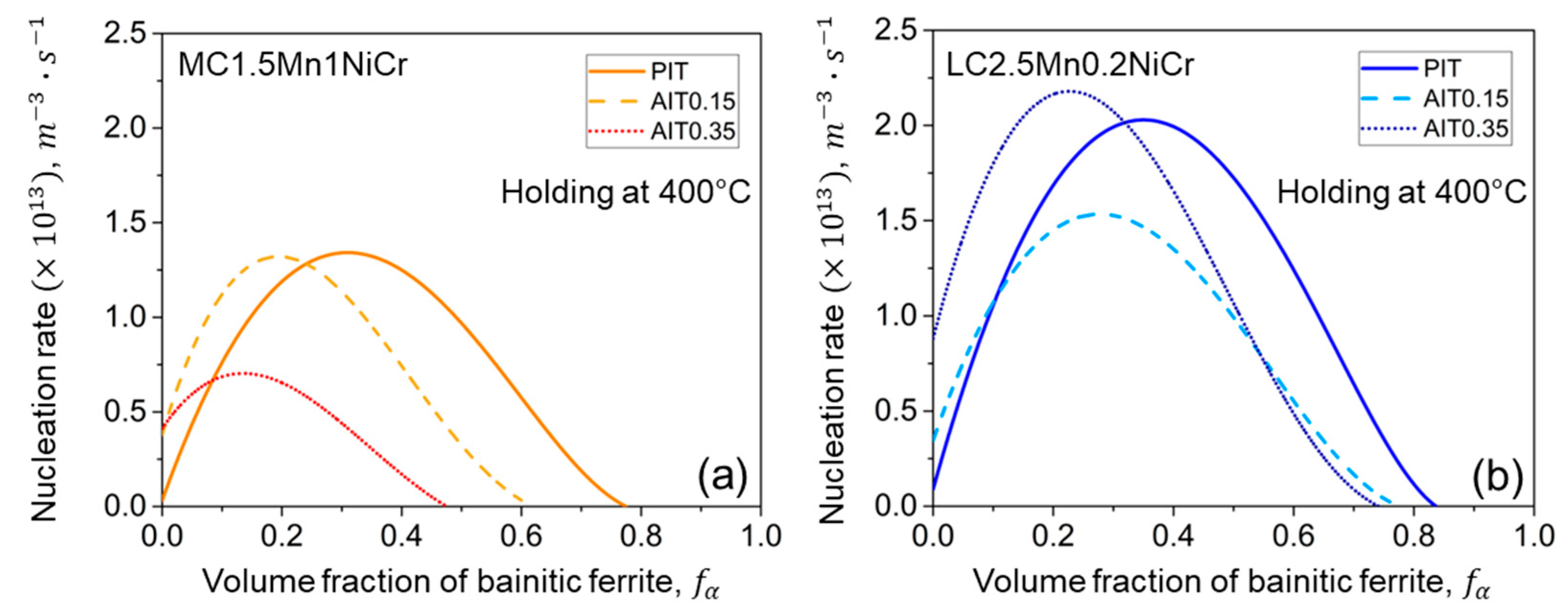
4.2.3. Kinetics of Bainitic Phase Transformation

Figure 4 displays the kinetics of the bainitic transformation of MC1.5Mn1NiCr and LC2.5Mn0.2NiCr steels under PIT and AIT conditions at different ausforming strains. It shows that the calculation results fitted very well with the experimental data. The transformation kinetics presented in Figure 4a,b could be divided into three stages, namely onset, growth, and cessation. The onset was indicated at a locus, at which the first BF sub-units were formed. After that, the growth driven by the shear was kinetically captured by the progress of the BF sheaves. Finally, the transformation stopped when the decomposition of austenite was supersaturated as it reached its plateau. Ausforming had a strong influence on an acceleration of the transformation onset and a reduction in the BF volume fraction. However, for MC1.5Mn1NiCr/AIT0.35 steel, the transformation was somewhat sluggish compared to the other conditions for the same material. This circumstance could be precisely explained by the nucleation rate activity and the driving energy, as given in the next section. According to the fact that ausforming enhances the austenite stability, even though the deformation simultaneously accelerated the transformation, the drastic increase in defect density in UA during the initial progress of bainitic transformation resulted in a reduction in the BF fraction. The results were consistent with those reported in [18,53,54], particularly in the MC1.5Mn1NiCr steel. It can be seen that increasing the ausforming strain in LC2.5Mn0.2NiCr steel gave a slight difference in the lowering of the fraction of BF. In light of the chemical variations, LC2.5Mn0.2NiCr steel with a lower carbon content with adjusted Cr and Ni alloying elements possessed higher BF fractions than MC1.5Mn1NiCr steel, regardless of the applied ausforming. It could be verified from their bulk carbon contents and the effective enrichment of carbon in austenite. Hence, it was not surprising that the lower carbon steel exhibited smaller fractions of BF, which is similar to [55].
The fitted values of w α , d s , Q 0 * , and K 1 obtained from the proposed model are shown in Table 5. Only w α and Q 0 * were well explicable with their physical meaning. The reduction of Q 0 * values signified a decreased energy barrier of the nucleation reaction and seemed remarkably diminished by the ausforming. This parameter was associated with the kinetics acceleration of the BF transformation due to the increased number of existing nucleation sites per unit volume in UA. Considering the lower value of Q 0 * presented in the MC1.5Mn1NiCr/AIT0.15 compared with that in the MC1.5Mn1NiCr/AIT0.35, it could be described by the higher number of nucleation sites or defect densities, which essentially contributed in the later stage of the bainitic transformation. In this respect, it was not surprising that the average amount of carbon concentration in the BF supersaturation ( w α ) became constricted with regard to the higher kinetics acceleration at the beginning and was most likely associated with more carbon enrichment. However, the w α values gathered for the present model were invariably smaller than the mean carbon concentration in the mole fraction of both of the examined MC1.5Mn1NiCr and LC2.5Mn0.2NiCr steels, namely 0.01185 and 0.00824, respectively, which is similar to Ravi’s work [27]. The silicon and aluminum additions allowed the specific energy for carbon enrichment and enabled austenite to consume with a certain amount of carbon during the enrichment process, as illustrated in Figure 5. By this model, the evolution of carbon enrichment could be evaluated by the rejection of carbon from the supersaturated BF sub-unit during the austenite decomposition. The presence of RA evidenced the effectiveness of the incomplete reaction that occurred when the austenite was stabilized by the carbon enrichment. Nonetheless, the net carbon value calculated from this model could not be directly compared with the corresponding experimental values in Table 2, because the remaining available carbon may be further partitioned during the subsequent transformation of FM.
As previously mentioned in Section 3.1.1, the kinetics of bainitic transformation was governed by the nucleation rate mechanism, i.e., the grain boundary nucleation and the autocatalytic nucleation. The initial nucleation rate was activated by the grain boundary nucleation, which depended only on the density of the nucleation sites. Subsequent nucleation rates were then controlled by the autocatalytic nucleation with regard to the spontaneous dissociation of the specific dislocation defects and the accumulated stored energy of the corresponding dislocations [56]. Moreover, a generation of additional defects by ausforming presumably provided more available sites while simultaneously deteriorating the activation energy of the nucleation. Enhancing the defect densities thus increased the nucleation rate by triggering the transformation onset. The nucleation kinetics of examined steels subjected to different conditions are presented in Figure 6. It was hereby agreed that at the earliest stage of BF formation the driving energy for nucleation was higher than the stabilization effect, owing to the potential nucleation sites, which were generated during either the ausforming or the cooling to the transformation temperature. The formation of BF continued until the driving energy for nucleation and stored energy due to the mechanically stabilized austenite, which became identical at the maximum nucleation rate. Hereafter, the deceleration kinetics occurred, implying that the stability of the neighboring austenite was increased by the successive formations of the BF sub-units, which resulted in a reduction in stored energy for the transformation. This occurrence could be verified by the relationship between the driving energy for the autocatalytic nucleation and the corresponding number of nucleation sites, as depicted in Figure 7. It is noteworthy that the nucleation rates and the driving energy values of LC2.5Mn0.2NiCr steel were all lower than those of the MC1.5Mn1NiCr steels, regardless of the heat-treated condition. This result was likely caused by the elemental distribution, which was similar to that observed in an experimental validation proposed by Wang et al. [4].
The autocatalytic driving energy could be also considered as an important factor for controlling the nucleation event. When the austenite stability became more dominant, the total driving energy stored for the phase transformation decreased. It can be observed that the driving energy was drastically increased at the initial stage of nucleus formation and then decreased gradually during the developing of the nucleation sites. The effect of ausforming almost caused degenerations of the nucleus development, accordingly, except that they occurred in MC1.5Mn1NiCr/AIT0.35 steel. The number of nucleation sites developed in the MC1.5Mn1NiCr/AIT0.15 steel was more extensive than in the MC1.5Mn1NiCr/AIT0.35 steel, which corresponded with lower driving energy, as presented in Figure 7a. Even though the MC1.5Mn1NiCr steel consumed less driving energy than the LC2.5Mn0.2NiCr steel, it had a small number of nucleation sites due to the existence of more dislocations. Interestingly, the driving energy of the LC2.5Mn0.2NiCr steels shown in Figure 7b was significantly sensitive to ausforming, and was well described, especially at the high degree of ausforming. From the correlation between the activation energy and the driving force defined in Equation (9), it was inevitable that the initial activation energy required to overcome any obstacles played an essential role in all the nucleation events. Nevertheless, in order to extract and consider only the activation energy influenced by the other mechanisms, regardless of the energy contributed by ausforming, it was reasonable to take the activation energy difference in Equation (15) into account so that a discussion of only the effect of chemical contribution on the variation of the activation energy difference, Δ Q * was conceivable.
In Figure 8, the variations of the total activation energy difference with the evolution of the BF formation of MC1.5Mn1NiCr and LC2.5Mn0.2NiCr steels under PIT and AIT conditions are illustrated. The carbon enrichment was presumed to be the main contributor for BF formation. It was found that the Δ Q * energies required in all the conditions of the MC1.5Mn1NiCr steel were somewhat higher than those of the LC2.5Mn0.2NiCr steel. Such a tendency corresponded well with those shown in [27,56], in which it was reported that the activation energy was dependent, on one hand, on the undercooling temperature. It was decreased with the increasing of the temperature as a higher defect density was generated. On the other hand, Δ Q * was partially governed by the chemical element addition. In particular, those containing more carbon content acting as an austenite stabilizing element could directly lead to suppression of the bainitic transformation, accompanied by the raising of the energy required for the nucleation event. The maximum Δ Q * energies obtained for both the MC1.5Mn1NiCr and the LC2.5Mn0.2NiCr steels with PIT treatment were consistently higher than those with other heat-treating conditions. It was because of the small number of potential nucleation sites in PIT steel. In this sense, the reduction of the Δ Q * energy with respect to the evolution of the BF formation should be associated with the increased number of nucleation sites, while the termination of BF development could be associated with an overconsumption of nucleation sites in UA. Hence, the result gave rise to more stable austenite.

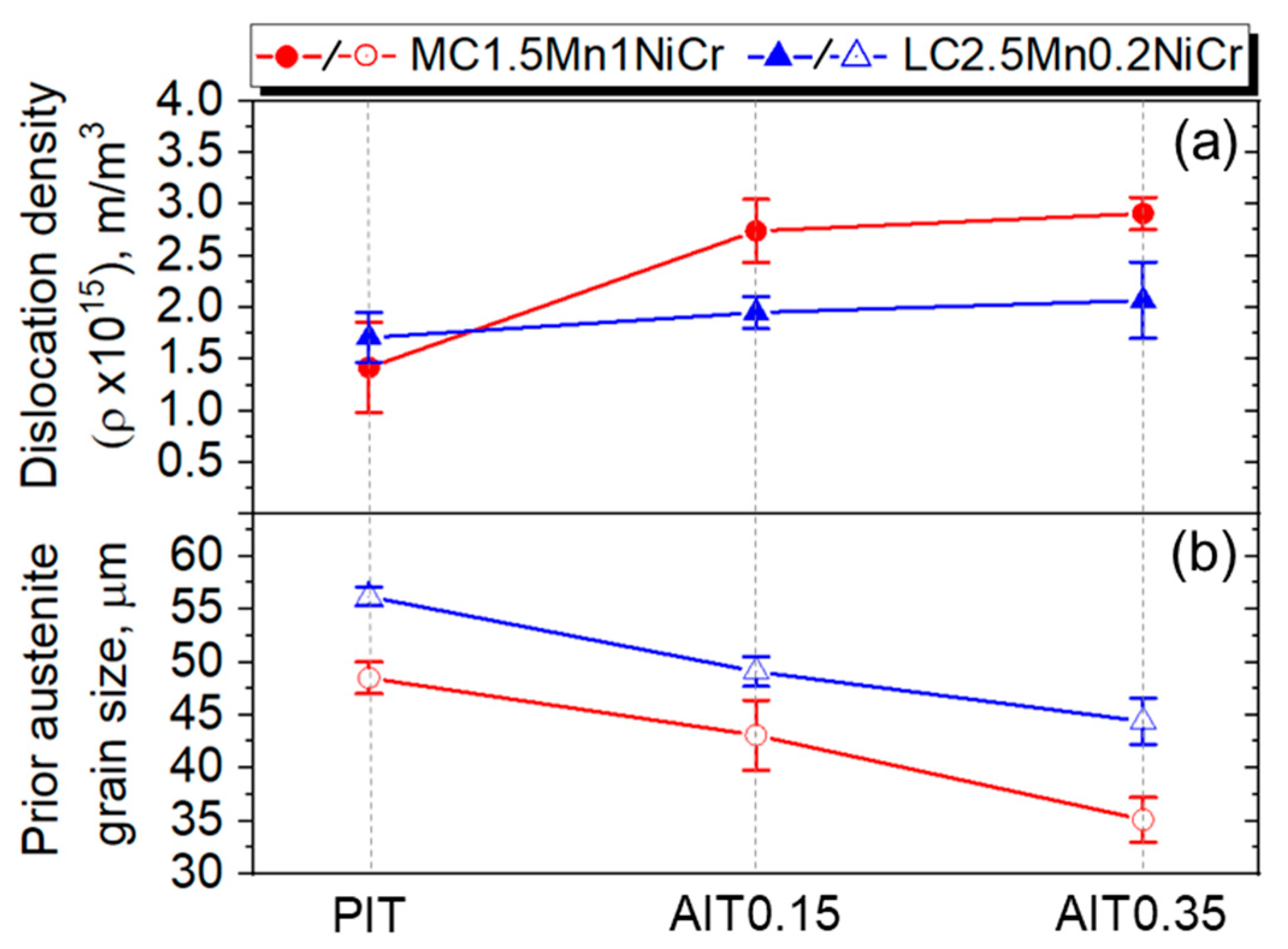
4.2.4. Dislocation Density Estimation

Figure 9a,b shows the estimated dislocation density and the PAGs of the steels under PIT, AIT0.15, and AIT0.35 conditions, respectively. As can be seen, the decreases in the PAGs were not the only factors affecting the density development of the dislocations in this study. The contribution of hard phases such as BF and FM should also be included as the formation of such structures was in fact accompanied by the accumulation of stress [57], particularly when the average dislocation density values estimated from the PIT specimens of individual steels were compared. However, the effect of carbon content on such PAG reduction could be described by the carbon-controlled nucleation mechanism during the solid solution treatment [58]. The influence of the PAGs was more pronounced in the ausformed specimens than in the PIT specimen, and thus it would be reasonable to describe it by the Hall–Petch relation [59].
Under the ausforming conditions, besides the PAGs reduction that came along with the pre-existing density of dislocations, the enhancement of the dislocation density was also associated with the fractions of the hard phase, as mentioned previously. The density of the pre-existing dislocation in the austenite was directly dependent on the ausforming strain, while the formations of BF and FM were governed by the thermodynamic stability of austenite and the degree of carbon enrichment, respectively. In addition, the pre-existing dislocation density affected by ausforming could be evaluated by subtracting the average density of the dislocations of any AIT specimen from the value estimated from the PIT specimen. For the LC2.5Mn0.2NiCr steel, the additional dislocations introduced by the 0.15 and 0.35 strains were 2.4 × 10 14 and 3.6 × 10 14   m 2 , respectively. Likewise, the estimated values of the MC1.5Mn1NiCr steel in accordance with the ausforming strains were 1.3 × 10 15 and 1.5 × 10 15   m 2 , accordingly. Such extra dislocations can be inherited further to the tempering region and change the nucleation activity during the bainitic transformation. Therefore, it could be concluded that the presence of higher dislocations in the MC1.5Mn1NiCr steel was likely due to a strong hindrance of the nucleation reaction, in which the effect of the dislocation-induced mechanical stabilization of austenite was more pronounced. However, the conclusion with respect to ausforming the enhanced thermal stability of austenite may not be applicable for the MC1.5Mn1NiCr steel as more FM was formed. In contrast, the deformation encouraged a higher nucleation activity and was mostly available for a greater formation of nucleation sites during bainitic transformation for the LC2.5Mn0.2NiCr steel. The results hereby enabled UA to be better stabilized after the transformation, although the ausformed LC2.5Mn0.2NiCr steels had a much lower density of dislocations. As a consequence, it seems that the relationship between nucleation sites and dislocation density evolutions could not be concluded as two different trends were seen in two different materials. Nevertheless, the LC2.5Mn0.2NiCr steel, with a substantial BF fraction due to the large degree of ausforming, effectively resisted the formation of FM by improving the thermal stability of austenite.

5. Conclusions/Summary

A model was formulated in this study to describe the effect of ausforming on the kinetics of isothermal bainitic transformation. The behavior of two low-carbon steels can be described based on nucleation control and the Koistinen–Marburger relationship. Different levels of ausforming were systematically characterized in experiments and further used to develop, calibrate, and validate the model. The model distinguishes grain boundary and autocatalytic nucleation. The associated driving energies are controlled by the chemical energy, interfacial energy, and stress-field energy caused by the formation of bainitic ferrite sub-units. The major conclusions are drawn in the following:
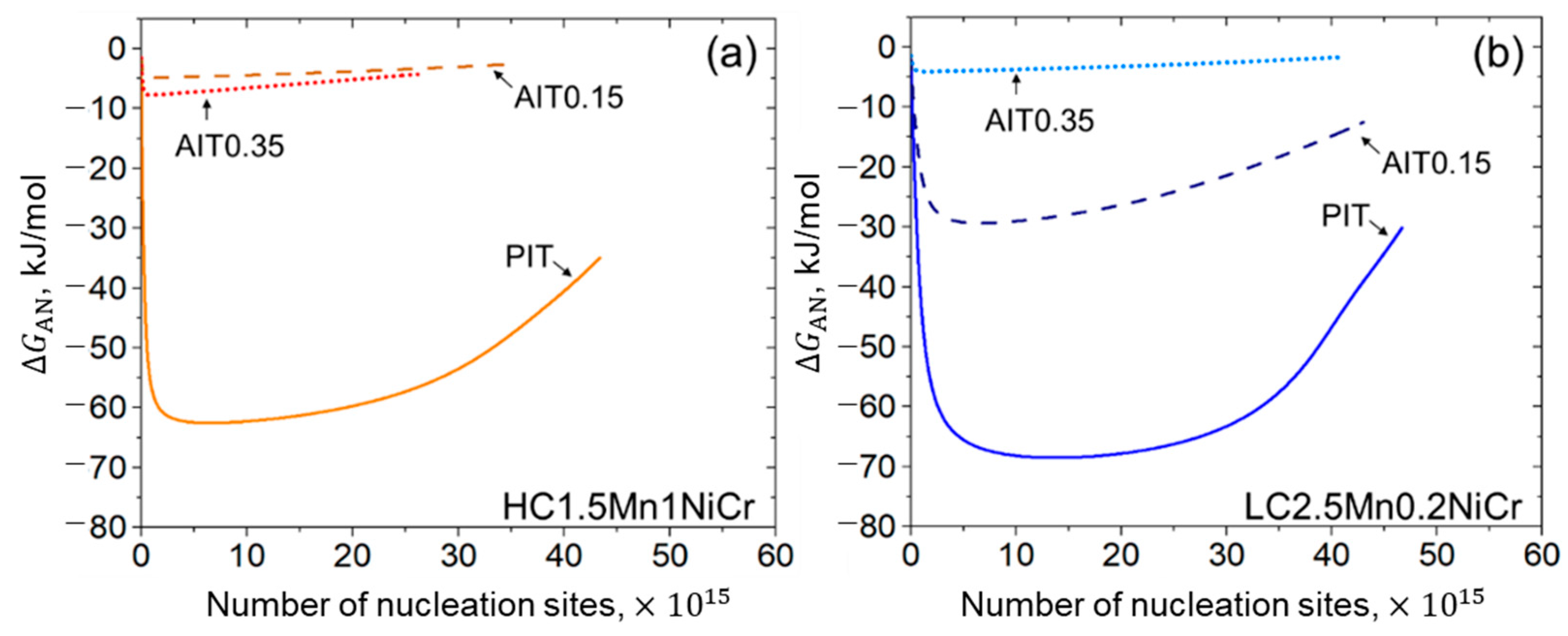
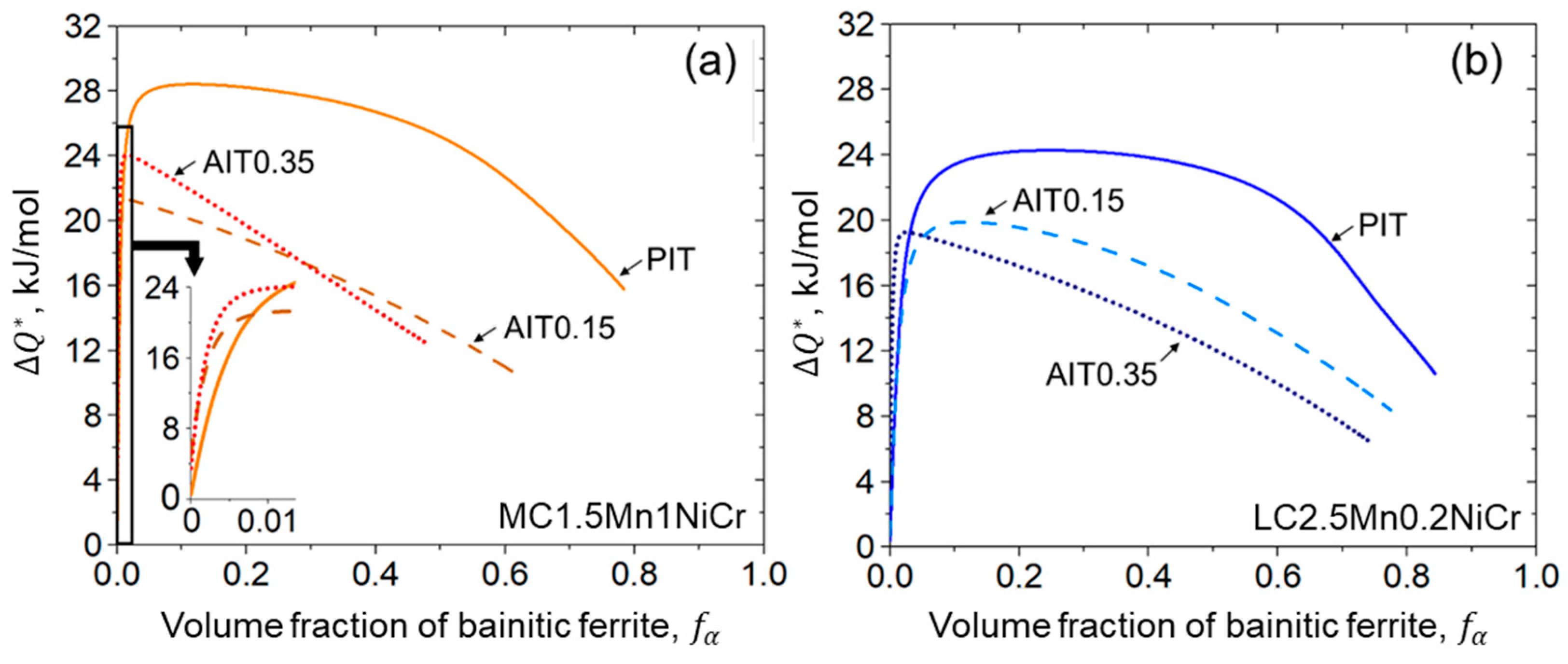
  • The formation of bainitic ferrite is mainly governed by two factors: carbon enrichment in austenite and the activation energy as an energy barrier required for nucleation.
  • Ausforming accelerates the onset of the bainitic phase transformation but results in sluggish transformation due to the mechanical stabilization of austenite. A higher degree of ausforming is more applicable in the steel with lower carbon content. With the substantial development of nucleation sites, even though they provide a slightly lower fraction of bainitic ferrite, the result effectively resists the formation of fresh martensite by improving the thermal stability of austenite.
  • A fitting parameter representing the initial energy barrier can be used to examine the activation energy change caused by ausforming. A decrease in the energy barrier allows the acceleration of the transformation. While the transformation progresses, the driving energy for autocatalytic nucleation becomes smaller due to the enhancement of the dislocation density.
  • The impact of carbon content plays a slight role in the onset period, but it is more pronounced during the progress of bainitic transformation. Minimizing carbon concentration in steel gives rise to a decrease in the net activation energy difference with the increasing of the nucleation rate. The result allocates a higher density of nucleation sites with more bainitic ferrite fractions.

Author Contributions

Conceptualization, T.K.; methodology, T.K.; validation, T.K., W.B., J.L. and V.U.; formal analysis, T.K.; data curation, T.K. and J.L.; writing—original draft preparation, T.K.; writing—review and editing, T.K., W.B., J.L. and V.U. All authors have read and agreed to the published version of the manuscript.

Funding

This research received no external funding.

Institutional Review Board Statement

Not applicable.

Informed Consent Statement

Not applicable.

Data Availability Statement

Not applicable.

Acknowledgments

The authors wish to thank Jiali Zhang from the Institute for Materials Applications in Mechanical Engineering, RWTH-Aachen University, for her assistance in using XRD measurement.

Conflicts of Interest

The authors declare no conflict of interest.

References

  1. Bhadeshia, H.; Edmonds, D.V. Bainite in silicon steels: New composition–property approach Part 1. Met. Sci. J. 1983, 17, 411–419. [Google Scholar] [CrossRef]
  2. Caballero, F.G. Carbide-free bainite in steels. In Phase Transformations in Steels; Elsevier: Amsterdam, The Netherlands, 2012; pp. 436–467. ISBN 9781845699703. [Google Scholar]
  3. Bhadeshia, H. Bainite in Steels: Transformations, Microstructure and Properties, 2nd ed.; IOM Communications: London, UK, 2001; ISSN 9781861251121. [Google Scholar]
  4. Wang, S.C.; Yang, J.R. Effects of chemical composition, rolling and cooling conditions on the amount of martensite/austenite (M/A) constituent formation in low carbon bainitic steels. Mater. Sci. Eng. A 1992, 154, 43–49. [Google Scholar] [CrossRef]
  5. Hofer, C.; Bliznuk, V.; Verdiere, A.; Petrov, R.; Winkelhofer, F.; Clemens, H.; Primig, S. Correlative microscopy of a carbide-free bainitic steel. Micron 2016, 81, 1–7. [Google Scholar] [CrossRef] [PubMed]
  6. Hofer, C.; Leitner, H.; Winkelhofer, F.; Clemens, H.; Primig, S. Structural characterization of “carbide-free” bainite in a Fe–0.2C–1.5Si–2.5Mn steel. Mater. Charact. 2015, 102, 85–91. [Google Scholar] [CrossRef]
  7. Hu, F.; Wu, K.M. Isothermal transformation of low temperature super bainite. Adv. Mater. Res. 2010, 146–147, 1843–1848. [Google Scholar] [CrossRef]
  8. Li, C.W.; Han, L.Z.; Luo, X.M.; Liu, Q.D.; Gu, J.F. Fine structure characterization of martensite/austenite constituent in low-carbon low-alloy steel by transmission electron forward scatter diffraction. J. Microsc. 2016, 264, 252–258. [Google Scholar] [CrossRef]
  9. Shimanov, M.; Korpala, G.; Terzic, A.; Kawalla, R. Bainitic steels: Their characteristics and applications. Key Eng. Mater. 2016, 684, 104–110. [Google Scholar] [CrossRef]
  10. Takahashi, M.; Bhadeshia, H. A model for the microstructure of some advanced bainitic steels. Mater. Trans. 1991, 32, 689–696. [Google Scholar] [CrossRef] [Green Version]
  11. Garcia-Mateo, C.; Sourmail, T.; Caballero, F.G. Bainitic Steel: Nanostructured. In Encyclopedia of Iron, Steel, and Their Alloys; Colás, R., Totten, G.E., Eds.; CRC Press: Boca Raton, FL, USA, 2016; pp. 271–290. ISBN 978-1-4665-1104-0. [Google Scholar]
  12. Caballero, F.G.; Santofimia, M.J.; García-Mateo, C.; Chao, J.; De Andrés, C.G. Theoretical design and advanced microstructure in super high strength steels. Mater. Des. 2009, 30, 2077–2083. [Google Scholar] [CrossRef] [Green Version]
  13. Garcia-Mateo, C.; Caballero, F.G. Advanced high strength bainitic steels. In Comprehensive Materials Processing; Elsevier: Amsterdam, The Netherlands, 2014; pp. 165–190. ISBN 9780080965338. [Google Scholar]
  14. Yao, Z.; Xu, G.; Hu, H.; Yuan, Q.; Tian, J.; Zhou, M. Effect of Ni and Cr addition on transformation and properties of low-carbon bainitic steels. Trans. Indian Inst. Met. 2019, 72, 1167–1174. [Google Scholar] [CrossRef]
  15. Changle, Z.; Hanguang, F.; Shengqiang, M.; Dawei, Y.; Jian, L.; Zhenguo, X.; Yongping, L. Effect of Mn content on microstructure and properties of wear-resistant bainitic steel. Mater. Res. Express 2019, 6, 86581. [Google Scholar] [CrossRef]
  16. Kumnorkaew, T.; Lian, J.; Uthaisangsuk, V.; Bleck, W. Effect of ausforming on microstructure and hardness characteristics of bainitic steel. J. Mater. Res. Technol. 2020, 9, 13365–13374. [Google Scholar] [CrossRef]
  17. Lee, C.H.; Bhadeshia, H.; Lee, H.-C. Effect of plastic deformation on the formation of acicular ferrite. Mater. Sci. Eng. A 2003, 360, 249–257. [Google Scholar] [CrossRef]
  18. Hase, K.; Garcia-Mateo, C.; Bhadeshia, H. Bainite formation influenced by large stress. Mater. Sci. Technol. 2004, 20, 1499–1505. [Google Scholar] [CrossRef] [Green Version]
  19. Matsuda, H.; Bhadeshia, H. Kinetics of the bainite transformation. Proc. R. Soc. Lond. A 2004, 460, 1707–1722. [Google Scholar] [CrossRef]
  20. Rees, G.I.; Bhadeshia, H. Bainitic transformation kinetics: Part 1. Modified model. Mater. Sci. Technol. 1992, 8, 985–993. [Google Scholar] [CrossRef]
  21. Magee, C.L. The kinetics of martensite formation in small particles. Metall. Mater. Trans. B 1971, 2, 2419–2430. [Google Scholar] [CrossRef]
  22. van Bohemen, S.M.C.; Sietsma, J. Modeling of isothermal bainite formation based on the nucleation kinetics. Int. J. Mater. Res. 2008, 99, 739–747. [Google Scholar] [CrossRef]
  23. Ghosh, G.; Olson, G.B. Kinetics of F.C.C. → B.C.C. heterogeneous martensitic nucleation-I. The critical driving force for athermal nucleation. Acta Metall. Mater. 1994, 42, 3361–3370. [Google Scholar] [CrossRef]
  24. Ghosh, G.; Olson, G.B. Kinetics of F.C.C. → B.C.C. heterogeneous martensitic nucleation-II. Thermal activation. Acta Metall. Mater. 1994, 12, 3371–3379. [Google Scholar] [CrossRef]
  25. Meng, Q.P.; Rong, Y.H.; Hsu, T.Y. Effect of internal stress on autocatalytic nucleation of martensitic transformation. Metall. Mater. Trans. A 2006, 37, 1405–1411. [Google Scholar] [CrossRef]
  26. Zou, H.; Hu, H.; Xu, G.; Xiong, Z.; Dai, F. Combined effects of deformation and undercooling on isothermal bainitic transformation in an Fe-C-Mn-Si alloy. Metals 2019, 9, 138. [Google Scholar] [CrossRef] [Green Version]
  27. Ravi, A.M.; Sietsma, J.; Santofimia, M.J. Exploring bainite formation kinetics distinguishing grain-boundary and autocatalytic nucleation in high and low-Si steels. Acta Mater. 2016, 105, 155–164. [Google Scholar] [CrossRef] [Green Version]
  28. Rees, G.I.; Shipway, P.H. Modelling transformation plasticity during the growth of bainite under stress. Mater. Sci. Eng. A 1997, 223, 168–178. [Google Scholar] [CrossRef]
  29. Zhou, M.; Xu, G.; Wang, L.; Xue, Z.; Hu, H. Comprehensive analysis of the dilatation during bainitic transformation under stress. Met. Mater. Int. 2015, 21, 985–990. [Google Scholar] [CrossRef]
  30. Lee, S.; Lee, S.J.; de Cooman, B.C. Austenite stability of ultrafine-grained transformation-induced plasticity steel with Mn partitioning. Scr. Mater. 2011, 65, 225–228. [Google Scholar] [CrossRef]
  31. Mahieu, J.; de Cooman, B.C.; Maki, J. Phase transformation and mechanical properties of si-free CMnAl transformation-induced plasticity-aided steel. Metall. Mater. Trans. A 2002, 33, 2573–2580. [Google Scholar] [CrossRef]
  32. Abrams, H. Grain size measurement by the intercept method. Metallography 1971, 4, 59–78. [Google Scholar] [CrossRef]
  33. Dyson, D.J.; Holmes, B. Effect of Alloying Additions on the Lattice Parameter of Austenite. J. Iron Steel Inst. 1970, 208, 469–474. [Google Scholar]
  34. Lutterotti, L.; Scardi, P. Simultaneous structure and size–strain refinement by the Rietveld method. J. Appl. Crystallogr. 1990, 23, 246–252. [Google Scholar] [CrossRef]
  35. Popa, N.C. The (hkl) dependence of diffraction-line broadening caused by strain and size for all Laue groups in Rietveld refinement. J. Appl. Crystallogr. 1998, 31, 176–180. [Google Scholar] [CrossRef]
  36. Warren, B.E. X-ray Diffraction; Dover Publications Inc.: New York, NY, USA, 1969; ISBN 9780201085242. [Google Scholar]
  37. Williamson, G.K.; Smallman, R.E., III. Dislocation densities in some annealed and cold-worked metals from measurements on the X-ray debye-scherrer spectrum. Philos. Mag. 1956, 1, 34–46. [Google Scholar] [CrossRef]
  38. Fielding, L.C.D. The Bainite Controversy. Mater. Sci. Technol. 2013, 29, 383–399. [Google Scholar] [CrossRef]
  39. Caballero, F.G. Bainitic Steel: Transformation Mechanisms and Properties. In Encyclopedia of Iron, Steel, and Their Alloys; Colás, R., Totten, G.E., Eds.; CRC Press: Boca Raton, FL, USA, 2016; pp. 291–305. ISBN 978-1-4665-1104-0. [Google Scholar]
  40. Ali, A.; Bhadeshia, H. Nucleation of Widmanstätten ferrite. Mater. Sci. Technol. 1990, 6, 781–784. [Google Scholar] [CrossRef]
  41. Bhadeshia, H.; Edmonds, D.V. The mechanism of bainite formation in steels. Acta Mater. 1980, 28, 1265–1273. [Google Scholar] [CrossRef]
  42. Tszeng, T.C. Autocatalysis in bainite transformation. Mater. Sci. Eng. A 2000, 293, 185–190. [Google Scholar] [CrossRef]
  43. Koistinen, D.; Marburger, R. A general equation prescribing the extent of the Austenite-Martensite transfor-mation in pure iron-carbon alloys and plain carbon steels. Acta Metall. 1959, 7, 59–60. [Google Scholar] [CrossRef]
  44. Olsen, G.B.; Cohen, M. Dislocation theory of martensitic transformations. In Dislocations in Solids; Nabarro, F.R.N., Ed.; Elsevier Science Publishers B.V.: Amsterdam, The Netherlands, 1986; pp. 293–408. [Google Scholar]
  45. Dong, H.; Sun, X. Deformation Induced Ferrite Transformation. In Ultra-Fine Grained Steels; Weng, Y., Ed.; Springer: Berlin/Heidelberg, Germany, 2009; pp. 86–136. ISBN 978-3-540-77230-9. [Google Scholar]
  46. Ghosh, G.; Raghavan, V. The kinetics of isothermal martensitic transformation in an Fe-23.2wt.%Ni2.8wt.%Mn alloy. Mater. Sci. Eng. A 1986, 80, 65–74. [Google Scholar] [CrossRef]
  47. Bhadeshia, H. MAP Program MAP_STEEL_MUCG83. Available online: http://www.phase-trans.msm.cam.ac.-uk/map/steel/programs/mucg83.html (accessed on 12 July 2021).
  48. van Bohemen, S.M.C.; Sietsma, J. Kinetics of martensite formation in plain carbon steels: Critical assessment of possible influence of austenite grain boundaries and autocatalysis. Mater. Sci. Technol. 2014, 30, 1024–1033. [Google Scholar] [CrossRef]
  49. Santofimia, M.J.; van Bohemen, S.; Sietsma, J. Combining bainite and martensite in steel microstructures for light weight application. J. S. Afr. Inst. Min. Metall. 2013, 113, 143–148. [Google Scholar]
  50. Capdevila, C.; Caballero, F.G.; De Andrés, C.G. Determination of Ms temperature in steels: A bayesian neural network model. ISIJ Int. 2002, 42, 894–902. [Google Scholar] [CrossRef] [Green Version]
  51. Lee, J.S.; van Tyne, C.J. A kinetics model for martensite transformation in plain carbon and low-alloyed steels. Metall. Mater. Trans. A 2012, 43, 422–427. [Google Scholar] [CrossRef]
  52. Wirths, V. Prozessführung und Zyklisches Werkstoffverhalten von Karbidfreien Bainitischen Stählen. Ph.D. Thesis, Rheinisch-Westfällischen Technischen Hochschule Aachen, Aachen, Germany, 2016. [Google Scholar]
  53. Shipway, P.H.; Bhadeshia, H. Mechanical stabilisation of bainite. Mater. Sci. Technol. 1995, 11, 1116–1128. [Google Scholar] [CrossRef]
  54. Hu, H.; Xu, G.; Wang, L.; Zhou, M.; Xue, Z. Effect of ausforming on the stability of retained austenite in a C-Mn-Si bainitic steel. Met. Mater. Int. 2015, 21, 929–935. [Google Scholar] [CrossRef]
  55. Soliman, M.; Palkowski, H. Development of the low temperature bainite. Arch. Civ. Mech. Eng. 2016, 16, 403–412. [Google Scholar] [CrossRef]
  56. Shah, M.; Kumar, D.S.; Ankita, P. Phenomenological kinetic model of the nano-bainitic steels to characterize the dynamics of the autocatalytic nucleation process. SN Appl. Sci. 2020, 2, 635. [Google Scholar] [CrossRef] [Green Version]
  57. PEET, M.J.; Bhadeshia, H. Surface relief due to bainite transformation at 473 K (200 °C). Metall. Mater. Trans. A 2011, 42, 3344–3348. [Google Scholar] [CrossRef] [Green Version]
  58. Castro Cerda, F.M.; Sabirov, I.; Goulas, C.; Sietsma, J.; Monsalve, A.; Petrov, R.H. Austenite formation in 0.2% C and 0.45% C steels under conventional and ultrafast heating. Mater. Des. 2017, 116, 448–460. [Google Scholar] [CrossRef]
  59. Narutani, T.; Takamura, J. Grain-size strengthening in terms of dislocation density measured by resistivity. Acta Metall. Mater. 1991, 39, 2037–2049. [Google Scholar] [CrossRef]
Figure 1. (a) Graphical illustrations of the isothermal decomposition of austenite into bainite for PIT and AIT specimens, and (b) schematic diagram showing relationships of Gibbs free energy, temperature, and composition of steels under various heat treatments. NS, GB, UA, BF, and FM stand for nucleation site, grain boundary, untransformed austenite, bainitic ferrite, and fresh martensite, respectively.
Alloys 01 00007 g001
Figure 2. (a) Phase quantifications of examined steels using XRD measurement and (b) volumetric strain of DQ and AIT specimens after cooling from austenitizing and deformation stage.
Alloys 01 00007 g002
Figure 3. Determination of the volume fraction of bainitic ferrite during tempering at 400 °C.
Alloys 01 00007 g003
Figure 4. The kinetics of bainitic transformation of (a) MC1.5Mn1NiCr and (b) LC2.5Mn0.2NiCr steels under PIT and AIT with the strain of 0.15 and 0.35.
Alloys 01 00007 g004
Figure 5. Relationship between the austenite decomposition and the degree of carbon enrichment in austenite of MC1.5Mn1NiCr steel with PIT condition.
Alloys 01 00007 g005
Figure 6. Nucleation rate as a function of BF volume fraction for (a) MC1.5Mn1NiCr and (b) LC2.5Mn0.2NiCr steels under various conditions.
Alloys 01 00007 g006
Figure 7. Driving force for autocatalytic nucleation as a function of density of nucleation sites of (a) MC1.5Mn1NiCr and (b) LC2.5Mn0.2NiCr steels under various conditions.
Alloys 01 00007 g007
Figure 8. Variation of total activation energy difference with bainite formation evolution of (a) MC1.5Mn1NiCr and (b) LC2.5Mn0.2NiCr steels under various conditions.
Alloys 01 00007 g008
Figure 9. (a) Dislocation density estimation and (b) prior austenite grain size of MC1.5Mn1NiCr and LC2.5Mn0.2NiCr steels under PIT, AIT0.15, and AIT0.35 treatments.
Alloys 01 00007 g009
Table 1. Chemical composition of the investigated steels in wt.%.
SteelFeCSiMnCrNiBTi
MC1.5Mn1NiCrBal.0.261.071.460.990.980.00310.027
LC2.5Mn0.2NiCrBal.0.180.972.500.200.210.00180.033
Table 2. Volume phase fraction determined by means of quantitative analysis of XRD measurement combined with the dilatometry results.
Material/ConditionVolume Fraction, % w γ , RA ( = x C )
Equation (3)
RABFFM
MC1.5Mn1NiCr/DQ--100-
MC1.5Mn1NiCr/PIT15.6 ± 3.377.4 ± 4.27.0 ± 2.80.78
MC1.5Mn1NiCr/AIT0.1514.6 ± 5.162.0 ± 6.723.4 ± 6.30.68
MC1.5Mn1NiCr/AIT0.3513.5 ± 5.847.9 ± 4.538.6 ± 3.40.56
LC2.5Mn0.2NiCr/DQ1.2 ± 0.8-98.5 ± 2.80.04
LC2.5Mn0.2NiCr/PIT8.5 ± 2.583.6 ± 4.67.9 ± 3.90.45
LC2.5Mn0.2NiCr/AIT0.1511.3 ± 3.777.6 ± 3.411.1 ± 4.50.51
LC2.5Mn0.2NiCr/AIT0.3516.9 ± 3.574.3 ± 4.98.8 ± 4.10.89
Table 3. Determined kinetics parameters using the modified KM equation for the examined MC1.5Mn1NiCr and LC2.5Mn0.2NiCr steels under PIT and AIT conditions.
Material/Condition α FM ,   K 1 n , M s , exp ,   C M s , cal , C
MC1.5Mn1NiCr/DQ0.02050.96354 ± 5.1344
MC1.5Mn1NiCr/PIT0.02050.96347 ± 4.7332
MC1.5Mn1NiCr/AIT0.150.02050.96260 ± 7.1255
MC1.5Mn1NiCr/AIT0.350.02050.96265 ± 6.3260
LC2.5Mn0.2NiCr/DQ0.02431.06388 ± 2.4380
LC2.5Mn0.2NiCr/PIT0.02431.06351 ± 4.2345
LC2.5Mn0.2NiCr/AIT0.150.02431.06270 ± 3.6263
LC2.5Mn0.2NiCr/AIT0.350.02431.06192 ± 5.8184
Table 4. Parameters used for the transformation models.
ParameterMC1.5Mn1NiCrLC2.5Mn0.2NiCr
PITAIT0.15AIT0.35PITAIT0.15AIT0.35
d γ , μ m 48 ± 1.543 ± 3.335 ± 2.156 ± 0.949 ± 1.444 ± 2.2
T iso ,   K 673673
T h X ¯ ,   K 753983
C 1 23042205
T 0   X ¯ ,   K 763778
C 2 89118537
Table 5. Fitting parameters obtained for the used model.
ParameterMC1.5Mn1NiCrLC2.5Mn0.2NiCr
PITAIT0.15AIT0.35PITAIT0.15AIT0.35
w α , mole fraction0.00910.00560.000810.00600.00480.0031
Q 0 * , kJ/mole172.98166.48170.9167.53164.83145.74
d s 1.4719.2612.031.814.369.73
K 1 0.464.867.320.360.691.29
Publisher’s Note: MDPI stays neutral with regard to jurisdictional claims in published maps and institutional affiliations.

