Abstract
Silk fibroin has emerged as a leading biomaterial for biomedical applications. 3D printing has been successfully used for printing with silk fibroin, albeit in the form of a bioink, in direct-write 3D printers. However, in the form of bioinks, stability and mechanical attributes of silk are lost. An innovative alternative to producing 3D printed solid silk constructs is silk milled into powder for printing in a binder jetting printer. In this work, we focus on characteristics of silk powder to determine suitability for use in 3D printing. Two different silk powders are compared with hydroxyapatite powder, a known biomaterial for biomedical constructs. We have investigated powder size and shape by Camsizer X2 and Scanning Electron Microscope and bulk behaviour, dynamic flow behaviour, and shear behaviour by FT4 powder rheometer. Preliminary printing tests were conducted in an in-house custom-built printer designed for silk powder. It was found that silk powder has low flowability and stability. Therefore, to print solely out of silk powder, a 3D printer design will need sophisticated techniques to produce flow to ensure even distribution and consistent thickness of powder layers during the printing process. It was also found that high concentrations of formic acid (>75 to 99 wt.%) can fuse particles and therefore be used as a binder ink for 3D printing. The printer design challenges for silk powder are discussed.
1. Introduction
Biopolymers are important biomaterials for healthcare applications, such as tissue engineering, as they are biocompatible, degradable, and may promote excellent cell adhesion and growth [1,2,3,4]. One type of biopolymer that has attracted a great deal of attention in recent years is silk fibroin due to its advantageous mechanical properties whilst maintaining high biocompatibility, low immunogenicity, limited bacterial adhesion, and controllable biodegradability [5,6]. Silk fibroin is produced by silkworms, spiders, mites, and some scorpions. It offers several benefits for biomedical applications; it degrades within the body generating non-toxic by-products, unlike synthetic polymers such as polylactide, polyglycolide, and polylactic coglycolide, which degrade hydrolytically producing acidic by-products [7,8,9]. Due to the slow degradation, the U.S. pharmacopeia has recognised silk fibroin as a non-degradable material because, after 60 d of implantation, it maintains approximately 50% of its structure [10]. However, such a relatively slow degradation of silk is beneficial in load-bearing applications, as the extended time allows for tissue regeneration and remodeling before material degradation.
Silk fibroin also exceeds other natural biopolymers in its mechanical properties, making it well suited to more demanding biomedical uses, such as load-bearing applications [5,6]. It was found that screws produced from silk for bone fixation devices exhibited good shear properties, were biocompatible, and could remain within rat femurs for up to 8 w [11]. Other studies, including by our group, have used silk fibroin microfiber/powder as a filler to enhance the mechanical properties of bone scaffolds [12,13].
3D printing of silk fibroin to create biomedical scaffolds and other constructs have assumed significance. Silk has mainly been used with Material Extrusion 3D printers in the form of bioinks. However, many beneficial mechanical properties are lost when used in this form. The highly ordered β-sheet nanocrystals that provide natural strength are lost during the dissolution of fibres to prepare bioink and cannot be fully recovered in regenerated silk materials. Silk bioinks based printed constructs also have poor properties as they form hydrogel type of products only [14,15,16,17,18,19]. An alternative to bioinks for 3D printing is powdered silk for powder-based 3D printing [20]. Since powder can be produced using top-down mechanical processing without requiring the dissolution of fibres, the native β-sheet structure of silk is mostly retained. Preserving native crystalline structure in powders may help maintain higher stability of printed products to heat, chemicals, and biodegradation than silk solution-based printed constructs [21].
Powder-based 3D printing technologies use several methods for binding powder particles together, including heat and lasers, to construct 3D forms. However, unlike inorganic powders used in such printers, silk, being an organic material, degrades and burns instead of melting when exposed to high temperatures. Except for using extremely fast heating rates, which is not a feasible proposition, it is not possible to melt process silk materials [22]. This property has limited the use of silk powder to be solely used in powder-based printers, commonly known as Binder Jetting printers.
3D printing of silk powder using Binder Jetting principles requires an understanding of how to bind particles. The control of powder flow properties is also vital for printing operation in any powder-based printer. In this work, powder characteristics have been measured using an FT4 Powder Rheometer. Characteristics, such as stability, permeability, and cohesion properties, play important roles in 3D printing, and need to be considered when designing the printer’s powder-management system. For example, powder permeability refers to how well a substance such as a liquid or a gas can pass through the bulk of the powder. Measuring this property will assist in understanding how well a binder solution can penetrate the powder bed, influencing printing layer height and solution volume. As part of powder characterisation, two types of silk powder and hydroxyapatite powder were investigated in this work. Binder Jetting printers often use ceramic powders, such as hydroxyapatite, for bone-tissue engineering and, therefore, was selected for a comparison with silk powder [23,24].
High concentrations of formic acid are known to break hydrogen bonds in the crystalline region to partially or fully dissolve silk, depending upon the time of contact [25,26,27]. When the formic acid evaporates, it results in the precipitation of the silk fibroin. This process was investigated as a fusing method for silk powder. Different concentrations of formic acid solutions were used to determine the most suitable range for use as a binder jet ink. Finally, some preliminary printing test results using a custom designed printer was performed to understand further development requirements for this printer.
2. Materials and Methods
2.1. Deakin University Produced Silk Powder
Referred to as ”Deakin silk powder”, manufacturing details were reported earlier [21]. Briefly, the B. mori silk cocoons were first degummed using 2 g/L sodium carbonate and 0.6 g/L sodium dodecyl sulphate in a dyeing machine at 98 °C for 30 min. After washing, they were chopped in a cutter mill, then wet-milled in a stirred media mill for 6 h, followed by spray drying to produce the powder.
2.2. Commercially Purchased Silk Powder
Commercially degummed and processed powder from B. mori fibres was purchased from Smiss Natural, Jiangsu, China, and used as supplied.
2.3. Hydroxyapatite Powder
The hydroxyapatite powder was sourced from Sigma-Aldrich (St. Louis, MO, USA), with batch number BCBS5188V.
2.4. Particle Size Analysis by Camsizer X2
The size and shape of the particles were analysed using a Camsizer X2 particle analyser from Retsch Technology (Haan, Germany). The Camsizer used two digital cameras to capture dispersed powder particles passed through two bright, pulsing LED light sources. One digital camera captures high-resolution photos for the finer particles, while the second digital camera captures images of the larger particles. These cameras scan each particle up to 64 angles. This data is then analysed by Camsizer software to determine the shape and size of each particle.
2.5. Scanning Electron Microscope (SEM)
A Zeiss Supra 55 vp scanning electron microscope, from ZEISS (Jena, Germany) was used using 3 kV accelerating voltage to image particles. Before SEM imaging, each powder sample was gold sputter-coated (Leica EM ACE600, from Leica microsystems (Wetzlar, Germany)).
2.6. Laser Scanning Microscope
An Olympus LEXT OLS4100 laser scanning digital microscope, from Olympus (Waltham, MA, USA), with a 20× Olympus 20×/0.60 LEXT objective lens was used to capture images of the samples in the benchtop silk particle fusion experiments. The captured images present the intensity of the surface topography of the samples, illustrating particle dissolution.
2.7. FT4 Powder Rheometer
The dynamic properties of powder were characterised using an FT4 Powder Rheometer (Freeman Technology, Tewkesbury, UK). Powder characterisation included stability, aeration, permeability, shear properties, and wall-friction properties. All experiments were carried out using a 25 mm × 10 mL split vessel, 25 mm × 25 mL split vessel, 25 mm × 35 mL split vessel, hardened stainless-steel 23.5 mm blade, vented piston, shear head, and a wall-friction head. Each experiment included one or several powder-conditioning procedures recommended by the manufacturer, which involved the gentle displacement of the powder with a 23.5 mm blade in constructing a homogenous powder bulk. Further details of the methodologies of each experiment using the FT4 powder rheometer was reported earlier [28,29].
2.7.1. Powder Stability Measurement
The stability of a powder refers to how reproducible the measurements of its characteristics are over time due to changes in powder behaviour after handling. This property directly affects the printing performance of the powder since an unstable powder would reduce its repeatability. Illustrated in Figure 1a, the stability experiment consisted of seven cycles of powder conditioning within a 25 mm × 25 mL split borosilicate glass vessel. A 23.5 mm blade was inserted into the powder sample and rotated with a circular velocity of 100 mm/s. For each cycle, a measurement was taken of the resistance the powder bulk exerts onto the rotating blade, which could be interpreted as measuring the flow of the powder. These measurements were used to calculate the stability index, specific energy, and conditional bulk density.
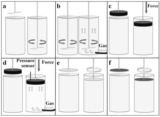
Figure 1.
Measurement methodology for (a) stability, (b) aeration, (c) compressibility, (d) permeability, (e) shear, (f) and wall friction.
Measuring the change in resistance, exerted onto the moving stainless-steel blade over multiple tests, expressed in Total Energy, we calculated the stability index, specific energy, and conditional bulk density with Equations (1)–(3), respectively.
Stability Index = Total Energy Test 7/Total Energy Test
Specific Energy (mJ/g) = ((The Rise in Energy on Cycle 6 + The Rise in Energy on Cycle 7)/2) × (1/Powder Mass)
Conditioned Bulk Density(g/mL) = Mass/Volume
2.7.2. Aeration Experiment
Measuring the gas permeability of the powder provides a lot of information on the cohesive properties of the powder particles. This is essential knowledge for printing since it determines the behaviour of the powder during the printing process, affecting performance. The aeration experiment required six conditioning cycles, implementing a 23.5 mm blade with a circular velocity of 100 mm/s embedded into the bulk of the powder as shown in Figure 1b. A gas (oxygen) was introduced from the base of a 25 mm × 35 mL split borosilicate glass vessel containing the powder. Each cycle included a measurement of the resistance the powder bulk exerted onto the blade, with each cycle consisting of an increment of 2 mm/s gas velocity, starting from 0 mm/s. These measurements were used to calculate the aeration ratio and aerated energy.
Calculations of powder’s aeration ratio, aerated energy, and change in Total Energy were governed by Equations (4)–(6), respectively.
Aeration Ratio = Total Energy at Gas Velocity 0 mm/s/Total Energy at Gas Velocity 10 mm/s
Aerated Energy (mJ) = Total Energy at Gas Velocity 10 mm/s
Change in Total Energy = Total Energy at Gas Velocity 0 mm/s − Total Energy at Gas Velocity 10 mm/s
2.7.3. Compressibility Measurement
Powder compressibility must be considered when printing, as there are different magnitudes of force being applied onto the powder at any given time during the printing process. If a powder has high compressibility, the change in force can lead to a non-uniform volume output over the period of the print and can cause a reduction in repeatability. After conditioning with a 23.5 mm blade at 100 mm/s circular velocity, the compression experiment utilised a vented piston to apply a normal force onto powder bulk, contained within a 25 mm × 10 mL split borosilicate glass vessel, illustrated in Figure 1c. Eight measurements of change in powder volume were taken at increasingly applied normal forces, ranging from 1 to 15 kPa. From these measurements, we could determine a powder’s compressibility, bulk density, and compression ratio.
Powder compression ratio, compressibility, and compressed bulk density were calculated using Equations (7)–(9), respectively.
Compression Ratio = Bulk Density @ 15 kPa/Bulk Density @ 0 kPa
Compressibility (%) = Percentage of volume change @ 15 kPa
Compressed Bulk Density (g/mL) = Bulk Density @ 15 kPa
2.7.4. Permeability Measurement
Powder permeability refers to how well gas can pass through the bulk of the powder when under a force. This further helps to understand the behaviour of the powder during a printing process in terms of particle interaction while under stress. The powder’s permeability also allows correlating the printer’s binder’s volume output and viscosity. After a conditioning cycle, a vented piston was used to apply eight normal forces increasing in magnitude onto the powder, which was contained within a 25 mm × 10 mL split borosilicate glass vessel. A gas (oxygen) was introduced into the powder at each increment of applied normal force, illustrated in Figure 1d, and after a time period (which allowed for the powder and gas to reach equilibrium) the pressure drop across the powder was measured. This pressure drop was calculated to give the resistance that the compressed powder created onto the gas, therefore determining how easily a gas/fluid can transmit through its bulk.
The permeability ratio and overall pressure difference were calculated using Equations (10) and (11), respectively.
Permeability Ratio = Pressure difference @ 15 kPa/Pressure difference @ 1 kPa
Overall Pressure difference (mBar) = Pressure difference @ 15 mBar − Pressure difference @ 1 mBar
2.7.5. Shear Experiment
Within a printing process, powder flowability is essential in determining how uniform the powder moves, how much energy is needed to move it, and what movement techniques are compatible. Evaluating internal frictions of powder help to understand its flowability and can be measured within the shear experiment. After a conditioning cycle, the powder was compressed with a compression cycle using a vented piston at 3 kPa. A shear head was introduced, which consisted of several perpendicular blades, as shown in Figure 1e. When the shear head applied a normal force, the blades embedded themselves into the powder before rotating to apply shear stress. A predetermined normal force was applied and maintained onto the powder by the shear head, increasing in circular force until the powder bulk failed. This point of failure is known as the ‘Point of incipient failure’ or the ‘Yield point’. This was repeated five times with predetermined normal forces of 3, 4, 5, 6, and 7 kPa, respectively. These measurements were used to determine powder cohesion property, unconfined yield strength, major principal stress, angle of internal friction and flow function. Shear experimentation can be found in supplementary documentation. Shear experiment results are shown in Figure S1.
2.7.6. Wall-Friction Experiment
To further understand the flowability of the powders, the friction between the powder and the internal surfaces of the printer also needs to be taken into consideration. After a conditioning cycle and compression cycle, a Freeman Technology wall-friction head with a flat surface of 0.28 µm roughness was utilised. This wall-friction head mimicked the surface of a container and was used to induce both a normal and rotational stress to the powder. At six increasingly applied normal forces, the wall-friction head induced a rotation force, illustrated in Figure 1f, which competed with the static friction force created by the powder and the friction head. The rotation force increased until it overcame the static friction. At this point, the friction head maintained a constant velocity and a measurement of the kinetic friction was taken, also known as the ‘steady-state’ shear stress. The applied normal forces were as follows: 3, 4, 5, 6, and 7 and 9 kPa. We found the powder’s wall-friction locus and wall-friction angle with these measurements and Equation (12).
Wall-Friction Angle = tan^(−1) (Max Applied normal stress (9 kPa)/Steady-State Shear Stress @ 9 kPa)
2.8. Silk Particle Fusion Experiment
Samples of 5 g of Deakin milled silk powder were placed within circular plastic dishes. Five formic acid solutions were prepared with the following concentrations: 0 wt.% (distilled water), 5 wt.%, 40 wt.%, 75 wt.%, and 99 wt.%.
The initial experiment used a binder/powder ratio of 3:2 by adding 7.5 mL of binder into the 5 g of silk powder. Once the binder was applied to the silk powder samples, they were left for 24 h at 23–24 °C. The next set of experiments were conducted by applying 50 µL of solution (99 wt.% formic acid or distilled water) in a rectangle pattern on the surface of packed silk powder samples. Then left for 24 h at 23–24 °C. The ability of formic acid to fuse silk particles by partially dissolving the particles were observed.
3. Results and Discussion
3.1. Particle Properties
The distributions of aspect ratios for the samples measured by Camsizer X2 are shown in Figure 2. The aspect ratio of Deakin silk powder was 0.80 ± 0.1, while that of commercial silk powder was 0.71 ± 0.13, and hydroxyapatite was 0.762 ± 0.11. Aspect ratio of a perfectly spherical particle equals one, and as the particle shape deviates more from a perfect sphere, the aspect ratio moves towards zero. Thus, the results suggest that the Deakin silk particles were more sphere-like in shape and commercial silk particles were the most irregular in shape. The aspect ratio distribution of Deakin silk powder was narrow, while commercial silk powder had the highest variation among the three powders tested.
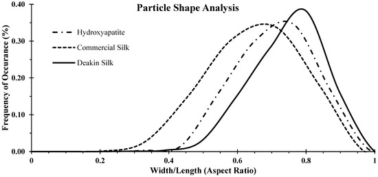
Figure 2.
Particle shape analysis of hydroxyapatite, commercial silk powder, and Deakin silk powder. Particle shape analysis comprises frequency of occurrence over respective aspect ratio presented in the x-axis.
Figure 3 shows the particle size distribution plot, and Table 1 presents the mean and median of particle diameter. Equivalent particle diameter computed by the Camsizer software was considered in this case. The results show that all samples had long tails in the size distribution plots, indicating the presence of large particles that skew the distribution plots; hence there were differences between the mean and median for each distribution. Hydroxyapatite particles were finer than silk powder, and Deakin silk particles were finer than commercial silk powder. However, the differences between them were small and hence powder bulk and follow properties are expected not to be influenced much by the size.
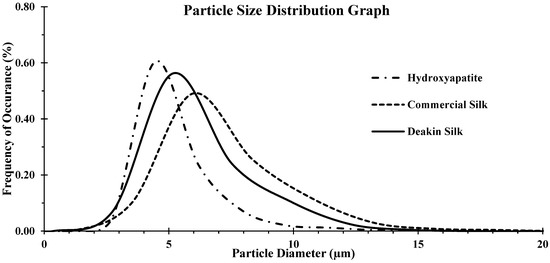
Figure 3.
Comparison of particle size distribution of hydroxyapatite, commercial silk powder, and Deakin silk powder.

Table 1.
Particle analysis results.
Under SEM, the Deakin silk particles appeared nearly spherical and more uniform in size distribution than other particles (Figure 4). Hydroxyapatite particles were reasonably spherical, but commercial silk particles were more prominent than others and far from being spherical. The results correlated well with the aspect ratio and particle size distribution trend provided by Camsizer. However, the difference was more distinct in SEM images compared to Camsizer results. The hydroxyapatite particles showed many smaller particles, which was not reflected in the Camsizer result presented in Figure 3. Likely, some sub-micron particles visible in SEM could not be measured by the Camsizer due to camera resolution or these particles were presented as aggregates in the Camsizer test. The maximum size of hydroxyapatite detected was approximately 10µm, while large particles were seen in the SEM image. It is possible that some of these large hydroxyapatite particles seen in SEM image were fragmented in the Camsizer measurement as particles are carried by a strong current of air for measurement. Hydroxyapatite is a brittle material, and such breakdown has been observed in other studies [30].
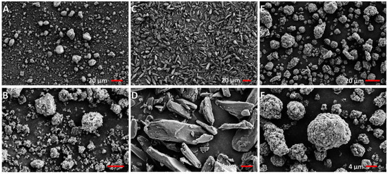
Figure 4.
SEM images of particles: (A,B) Hydroxyapatite; (C,D) Commercial silk powder; and (E,F) Deakin silk powder.
The spherical morphology and narrower size distribution of Deakin silk particles could be attributed to the manufacturing method involving wet milling and spray drying. The commercial silk powder manufacturing method is not known; however, we had produced particles similar to commercial silk by dry milling following acid/alkaline hydrolysis of silk. The difference in the size of particles and the aspect ratio could influence their bulk, cohesion, and dynamic properties, which are essential factors for powder printing.
3.2. Powder Stability Measured by FT4 Rheometer
Instability of powder material may occur if a powder is prone to attrition or agglomeration when under stress, resulting in changes in flow, particle shape, or size. Figure 5 shows the stability comparisons of the 3 types of powder materials over 7 identical tests performed in FT4 based on the methodology discussed in the experimental section.
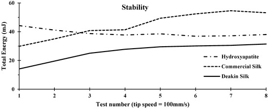
Figure 5.
Stability comparison of hydroxyapatite, commercial silk powder, and Deakin silk powder. Stability graph comprises of the measured Total Energy (mJ) over test number.
The stability index is a ratio of the results from Test 7 over those from Test 1; according to Equation (1), it indicated if powder properties have changed from the stresses caused by the rotation of the blade within the bulk of the powder over the period of the tests. A completely stable powder that remained the same without changing form or properties will have a stability index of 1. More deviation of the stability index from 1 indicates a more unstable powder. An unstable powder will create problems in printing as the amount of powder flow per cycle of printing, and properties, such as powder density, will change accordingly, resulting in a reduction of repeatability with increased variations in printed products.
As shown in Table 2, hydroxyapatite powder was the most stable, followed by commercial silk and Deakin silk powder, which was the least stable powder. Many factors contribute to a powder’s stability index. Hydroxyapatite demonstrated a loss in Total Energy over the tests shown in Figure 5, with a stability index of less than one. This signified that the particles experienced attrition, which led the particle to break into smaller, rounder particles, reducing the Total Energy required to rotate the blade in the subsequent cycles in the stability test. This is likely due to the brittle nature of hydroxyapatite powder.

Table 2.
Stability experiments results.
In conducting the stability experiment, it was observed that both silk powders showed signs of agglomeration within the glass vessel. Agglomeration made powder more cohesive, resulting in more Total Energy required after each cycle in the stability test. As both silk powders had a broader size distribution compared with hydroxyapatite (seen in Figure 3), it was likely that in such powders, smaller particles filled voids between larger particles, thereby increasing particle density and escalating Total Energy. Another possible cause was static charge build-up. Protein fibres generate a static charge, and fibre powders have a higher surface area with a greater degree of static charge generation. This property, therefore, must be taken into consideration as it would also decrease stability in the printing process.
Commercial silk showed the highest Total Energy required overall to produce flow within the powder (Figure 5), which was significantly higher than the Deakin silk powder. Commercial silk powder was found to require almost double the specific energy to produce flow compared to Deakin silk (Table 2). This could be primarily due to the difference in particle shape (illustrated in Figure 2), as flat-shaped particles could cause increased interlocking during the tests. High specific energy indicated a large amount of friction or mechanical interlocking occurred within the moving powder.
3.3. Aeration
The aeration experiment aimed to measure how introducing gas flow through the bulk of the selected powders changed their behaviour. These measurements indicate how the dynamic flow behaviour could be enhanced with gas flow.
Results presented in Figure 6 and Table 3 show that the Deakin powder required significantly less energy to rotate the blade through the powder during gas flow compared to the other two powders in all cycles. Hydroxyapatite was affected the most by introducing gas, with a Total Energy change of 31.56 mJ and a resulting aeration ratio of 3.33 mJ. This indicated that the hydroxyapatite powder allowed the gas to pass through its particles to the extent which lowered their mechanical friction forces and interlocking, reducing the Total Energy to produce flow.
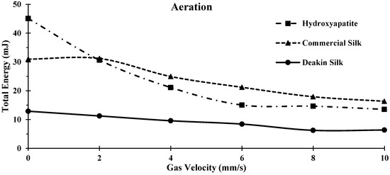
Figure 6.
Comparison of Aeration between hydroxyapatite, commercial silk powder, and Deakin silk powder.

Table 3.
Aeration experiment results.
The commercial silk had a change in Total Energy of 14.64 mJ (Table 3). The change in aeration energy of commercial silk powder was significantly higher than the Deakin silk powder. This was likely due to the irregular shape and larger surface energy, and cohesion of the commercial silk powder. Deakin silk was the least affected powder by introducing gas flow with a change in Total Energy of 6.52 mJ. These particles were more spherical and, hence, are likely to be more aerodynamic. Therefore, the gas would produce less upward force onto each particle, reducing the effects of gas flow and, thus, maintaining a lower change in Total Energy.
3.4. Compressibility
Compressibility was calculated by measuring the change of volume and bulk density against increasing order of applied pressure (0–15 kPa; Figure 7 and Figure 8).
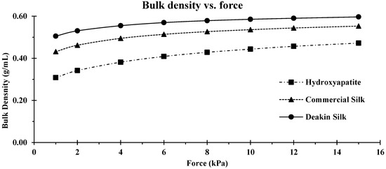
Figure 7.
Comparison of bulk density vs. compression force for hydroxyapatite, commercial silk powder, and Deakin silk powder.
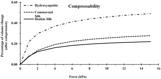
Figure 8.
Compressibility of hydroxyapatite, commercial silk powder, and Deakin silk powder.
The compressibility of a powder is heavily impacted by particle shape and size deviation. More spherical particles generally have less space between the particles, increasing bulk density and resulting in lower compressibility. Similarly, powders with a wide particle size distribution also generally contain high bulk densities, as the smaller particles can fit in the voids between larger particles. Other properties, such as attrition and de-aeration, can also affect compressibility.
Hydroxyapatite was the most compressible of the three powders; the volume of this powder was reduced by almost half at 15 kPa (Figure 8). Hydroxyapatite had a narrower particle size distribution than silk particles, meaning there was less scope for smaller particles to fall between larger particles resulting in higher compression. In addition, since hydroxyapatite is brittle, some amount of attrition was likely during the test, further increasing the compressibility compared to the two silk powders.
Commercial silk powder had a lower bulk density than Deakin silk powder which was attributed to irregular shape, as shown in Figure 2. More spherical Deakin particles packed better, producing a higher bulk density. However, the wider size distribution of the commercial silk powder improved packing, and, hence, the bulk density of the commercial silk powder was not much lower than the Deakin silk powder (Table 4).

Table 4.
Compressibility results.
3.5. Permeability
The permeability experiment aimed to measure how easily a gas or fluid could transmit through the bulk of the selected powders when the powder was under stress. These measurements suggest how efficiently a gas can be removed from the powder and how easily a binder can penetrate the bulk of the powder. Utilising a vented piston to compress the powders at several applied normal stresses, between 1 to 15 kPa, a gas was introduced at the base of the powder bed. Once the powder reached equilibrium, a pressure measurement was taken at the powder surface and gas entrance, allowing the pressure difference to be calculated across the powder’s bulk at each compression level.
Figure 9 shows that hydroxyapatite had a slightly higher permeability when compared to the two silk powders. However, when compressed, hydroxyapatite became the least permeable powder of the three, as seen by the high-pressure difference across the powder bed at around 15 kPa. As shown in Figure 8 and Table 5, hydroxyapatite experienced a high rise in bulk density when compressed, indicating that the air in between the particles got smaller. Decreasing the space meant less gas could flow through, therefore, resulting in a higher pressure difference. Like the high compressibility, the cause of low permeability when compressed was a result of the powders brittleness, leading to attrition, increasing bulk density, and lowering permeability.
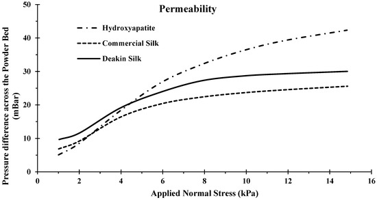
Figure 9.
Permeability of hydroxyapatite, commercial silk powder, and Deakin silk powder.

Table 5.
Permeability results.
Commercial silk and Deakin silk produced very similar results, with an average variance of pressure difference across the compression levels of around 3 kPa. From the compressibility experiment, we observed that the Deakin silk had a higher overall bulk density than the commercial silk, which would lead to a lower permeability (Figure 9). However, from the compressibility experiment, we also observed that hydroxyapatite had a lower bulk density and experienced lower permeability. This would be due to the attrition, as generally smaller particles exhibit lower permeability. Hydroxyapatite was recorded to have the smallest particles (Figure 9). When the powder experienced attrition, the particles became even smaller, filling space where it was possible for gas flow to occur, increasing permeability substantially.
3.6. Shear
Details of shear test measurement are presented in the supplementary section. The summary of the results is presented in Table 6. Flow function is a parameter commonly used to rank the flowability of powders. It was found that Deakin silk had the highest ranking of 3.19, followed by hydroxyapatite with 2.67, then commercial silk with a similar result of 2.63. Generally, when the flow function is <1, the powder is considered non-flowing; furthermore, the powder is deemed to be free-flowing when the flow function is >10. This suggested that Deakin silk powder had better flowability than the other two powders, though all three powders were relatively cohesive and less flowable. Usually, flow properties can be improved by coating or the use of solid lubricants. For 3D printing, the powders may need to be modified if low followability hinders their movement during the powder transfer to the printing volume.

Table 6.
Shear results.
3.7. Wall Friction
The wall-friction experiment aimed to examine how easily the selected powders began to flow from a consolidated state in relation to a material representing the surface of a wall or container. Using a wall-friction head, the powders were applied with a normal stress, at which the wall-friction head applied a rotating stress (torque). Once the powder bed failed, the wall-friction head continued rotating, which enabled the measurement of the required torque to compete with the kinetic friction produced by the powder.
Seen in Figure 10 and Table 7, it was found that Deakin silk had the lowest wall-friction angle of 27.83 degrees, followed by hydroxyapatite of 28.02, then commercial silk of 33.53. A powder’s wall-friction angle is influenced by its particle’s shape, size, and size distribution. The test results correlated with other properties measured by FT4. Spherical particles have lower contact, therefore, lower friction to the wall-friction head, reducing the wall-friction angle explaining the low Deakin silk result. Hydroxyapatite had a lower particle size distribution, resulting in less contact to the wall friction, in addition to the lowest bulk density, reducing normal gravity force, further reducing wall-friction angle. Commercial silk had the highest wall-friction angle, which could be explained by broader size distribution and higher irregular shaped particles.
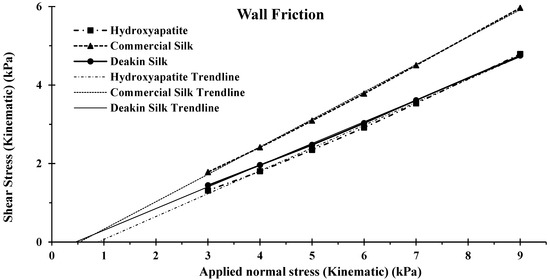
Figure 10.
Wall friction of hydroxyapatite, commercial silk powder, and Deakin silk powder.

Table 7.
Wall friction results.
3.8. Observing Fusion of Silk Particles
The aim was to determine if formic acid could be used to fuse silk particles to consider using it as a binder ink in 3D printing. Shown in Figure 11 are microscopic images of silk powder samples with a variation of formic acid solution concentrations. There were few visible signs of particle dissolutions in samples up to 40 wt.%. Samples with 75 wt.% and 99 wt.% formic acid did show degrees of dissolution. Circled in yellow is a blotch of dissolved particles when using 75 wt.% formic acid, indicating that the distribution of the dissolution particles was not even across the powder. However, 99 wt.% formic acid solution was found to dissolve silk particles and more evenly. This indicated that the formic acid concentration can influence the distribution of particle dissolution across a printer’s powder bed.

Figure 11.
Microscopic images of silk particles illustrating no particle fusing ((A)—40 wt.% formic acid as a binder), some particle fusing ((B)—75 wt.% formic acid as a binder), and majority of particle fusing ((C)—99 wt.% formic acid as a binder). Yellow circle showing a blotch of silk particle fusing with 75 wt.% formic acid as a binder.
To further investigate silk particle fusion, silk powder constructs were made by applying 50 µL of solution of 99 wt.% formic acid on the surface of packed silk powder samples, then left for 24 h at 23–24 °C. Water was used as control, and construct results are presented in Figure S2. The structure collapsed and disintegrated in water-treated samples. Figure 12 shows SEM images of a sample developed using 99 wt.% formic acid demonstrating particle dissolution. When the constructs were submerged for 24 h in water, they maintained structural shape; however, they lost an average weight of 40% ± 3. The weight loss was from loose powder surrounding the solid internal structure. This experiment indicates that high concentrations of formic acid (75 to 99 wt.%) can be used as a binder solution for silk powder.
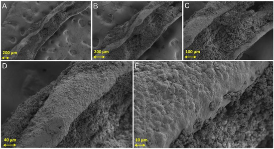
Figure 12.
SEM images of a construct produced with silk powder and formic acid as the binder. SEM images focused on the solid structure. (A–E) show increasingly magnified images of the construct.
3.9. Preliminary 3D Printing and Associated Challenges Powder
With the preliminary investigations into silk powder behavioural characteristics and the development of a particle binding method, an in-house custom-built 3D printer was designed and manufactured (Figure 13). Figure 13 shows an initial printed construct developed solely from silk powder. The design and evaluation of the silk 3D printer and initial printed construct are outside of the scope of this paper. This work is present elsewhere [31].
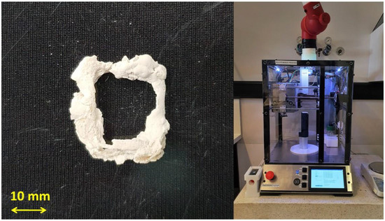
Figure 13.
(Left) initial printed construct developed solely out of silk powder; and (right) in-house custom-build 3D printer for the use of silk powder.
The powder management systems within powder-based printers usually consist of three essential tasks. First, an accurately measured volume must be moved from the storage container to the printing volume. Next, the powder must be spread evenly over the powder printing volume. Finally, the powder should be stored within the required storage container. This is an important task since the layer thickness of the powder defines the resolution and accuracy of the printing process. The behaviour of the powder influence how well and effectively a printer can complete these tasks.
The techniques chosen to move the powder rely mainly on the powder’s dynamic flow and shear behaviour. Powders with a high flowability and stability (determined by the flow function and stability index) require less energy to move and control. This allows for a more straightforward powder management system, such as using gravity feeding methods. However, a challenge faced with the two silk powders was that they had low stability and flowability. As a result, mechanical means will be needed to produce flow within the powders. Furthermore, the chosen flow technique will be needed to restrict the powder’s tumbling, and not cause unwanted agglomeration, attrition, and segregation. It is crucial to ensure the powder behavioural characteristic consistency to enable printing repeatability.
Another challenge that will arise is the difficulty of ensuring even distribution and a consistent amount of silk powder over the printing volume on each layer. Flowability influences layer thickness as it contributes to how well a powder can be spread. Therefore, layering processes for silk powder will need to be sophisticated enough to disperse and flatten low flowable powders by either applying multiple smoothing cycles per layer, gradual horizontal powder releases, improving powder flow by process control agents or using a combination of these.
The bulk density of the two silk powders was found to be higher compared to the hydroxyapatite powder. Bulk density influences the penetration and dispersion of binder solution and can be seen in Figure 9 where both silk powders were found to have higher initial permeability. This suggests that the printer’s binder supply system will need to be precise to prevent undesired binder dispersion, resulting in misshaped constructs. Furthermore, achievable layer thickness will need to be measured, as maximum binder penetration is directly linked to maximum layer height within powder printers.
One of the more significant challenges for 3D printing silk powder is the binder solution. High concentrations of formic acid were found to enable the fusion of silk particles. However, such a solution would cause damage to internal components of binder supply systems in existing commercial Binder Jetting printers. This issue has been addressed in one study, where non-corrosive components were replaced and integrated into an existing Binder Jetting printer [32]. This included integrating polypropylene and polytetrafluoroethylene (PTFE) fluid lines and an inert glass reservoir into a ZPrinter 450. Therefore, it is possible to fabricate a binder supply system for this specific application.
This is the first attempt to understand the influence of particle size and shape on dynamic properties and we have done the preliminary work on printability. In the future we will be attempting to modify the particle flow properties by surface treatments such as use of lubricants and will also understand the impact of shape and size on printability and properties of printed products such as strength. Furthermore, we will investigate the optimisation of the 3D printing system, assessment of silk printed construct properties, and evaluation of silk powder feasibility and efficiency for the use in 3D printers.
4. Conclusions
The measured powder characteristics of the two silk powders identified several challenges that may occur when attempting to design and fabricate a 3D printer that will print solely from silk powder. The flowability and stability of these two powders will create issues for the printer’s powder-management system. Sophisticated techniques will need to be implemented to produce flow within the powder without causing unwanted agglomeration, attrition, and segregation. Furthermore, powder-depositing techniques, such as multiple smoothing cycles per layer or gradual horizontal powder releases, will need to be investigated to ensure the evenly distributed and consistent thickness of powder layers during the printing process.
It was found that a formic acid solution with a concentration of >75 to 99 wt.% would cause particle dissolution, and after a period, cause precipitation, enabling the fusion of silk particles. However, such a solution would cause damage to internal components of binder supply systems in existing commercial Binder Jetting printers. A new binder supply system will need to be developed with non-corrosive components to enable the use of highly acid solutions. Furthermore, the binder supply system would need to be precise to prevent binder dispersion due to the measured permeability of the two silk powders. With the preliminary investigations into silk powder behavioural characteristics and the development of a particle binding method, an in-house custom-built 3D printer was able to be designed and manufactured.
Supplementary Materials
The following supporting information can be downloaded at: https://www.mdpi.com/article/10.3390/powders1020009/s1, Figure S1: Shear (shear stress vs. applied normal stress); Figure S2: SEM images of a construct produced with silk powder and water as the binder. Images A–D show increasingly magnified images of the construct. Reference [33] is cited in the supplementary materials.
Author Contributions
D.W.: conceptualization, methodology, data curation, formal analysis, investigation, validation, visualization, writing—original draft, writing—review and editing, and software. B.J.A.: conceptualization, methodology, investigation, resources, supervision, and writing—review and editing. A.Z.K.: conceptualization, methodology, investigation, supervision, and writing—review and editing. X.W.: conceptualization, methodology, investigation, resources, and writing—review and editing. R.R.: conceptualization, methodology, investigation, project administration, resources, supervision, and writing—review and editing. All authors have read and agreed to the published version of the manuscript.
Funding
This research received no external funding.
Institutional Review Board Statement
Not applicable.
Informed Consent Statement
Not applicable.
Data Availability Statement
Not applicable.
Acknowledgments
We thank Anthony Antic, for his assistance and knowledge of the laboratory equipment used to gather the data for this research. We would like to also show our gratitude to Rechana Remadevi for her wisdom and assistance during the course of this research.
Conflicts of Interest
The authors declare no conflict of interest.
References
- Ko, H.F.; Sfeir, C.; Kumta, P.N. Novel synthesis strategies for natural polymer and composite biomaterials as potential scaffolds for tissue engineering. Philos. Trans. A Math. Phys. Eng. Sci. 2010, 368, 1981–1997. [Google Scholar] [CrossRef] [PubMed]
- van Vugt, T.A.; Geurts, J.A.P.; Arts, J.J.; Lindfors, N.C. Biomaterials in treatment of orthopedic infections. In Management of Periprosthetic Joint Infections (PJIs); Woodhead publishing: Amsterdam, The Netherlands, 2017; pp. 41–68. [Google Scholar]
- Chen, Q.; Liang, S.; Thouas, G.A. Elastomeric biomaterials for tissue engineering. Prog. Polym. Sci. 2013, 38, 584–671. [Google Scholar] [CrossRef]
- Moradali, M.F.; Rehm, B. Bacterial biopolymers: From pathogenesis to advanced materials. Nat. Rev. Microbiol. 2020, 18, 195–210. [Google Scholar] [CrossRef] [PubMed]
- Wlodarczyk-Biegun, M.K.; Del Campo, A. 3D bioprinting of structural proteins. Biomaterials 2017, 134, 180–201. [Google Scholar] [CrossRef]
- Mottaghitalab, F.; Hosseinkhani, H.; Shokrgozar, M.A.; Mao, C.; Yang, M.; Farokhi, M. Silk as a potential candidate for bone tissue engineering. J. Control. Release 2015, 215, 112–128. [Google Scholar] [CrossRef]
- Wenk, E.; Merkle, H.P.; Meinel, L. Silk fibroin as a vehicle for drug delivery applications. J. Control. Release 2011, 150, 128–141. [Google Scholar] [CrossRef]
- Numata, K.; Cebe, P.; Kaplan, D.L. Mechanism of enzymatic degradation of beta-sheet crystals. Biomaterials 2010, 31, 2926–2933. [Google Scholar] [CrossRef] [Green Version]
- Keirouz, A.; Zakharova, M.; Kwon, J.; Robert, C.; Koutsos, V.; Callanan, A.; Chen, X.; Fortunato, G.; Radacsi, N. High-throughput production of silk fibroin-based electrospun fibers as biomaterial for skin tissue engineering applications. Mater. Sci. Eng. C 2020, 112, 110939. [Google Scholar] [CrossRef]
- Melke, J.; Midha, S.; Ghosh, S.; Ito, K.; Hofmann, S. Silk fibroin as biomaterial for bone tissue engineering. Acta Biomater. 2016, 31, 1–16. [Google Scholar] [CrossRef] [Green Version]
- Perrone, G.S.; Leisk, G.G.; Lo, T.J.; Moreau, J.E.; Haas, D.S.; Papenburg, B.J.; Golden, E.B.; Partlow, B.P.; Fox, S.E.; Ibrahim, A.M.; et al. The use of silk-based devices for fracture fixation. Nat. Commun. 2014, 5, 3385. [Google Scholar] [CrossRef] [Green Version]
- Zhang, J.; Allardyce, B.J.; Rajkhowa, R.; Kalita, S.; Dilley, R.J.; Wang, X.; Liu, X. Silk particles, microfibres and nanofibres: A comparative study of their functions in 3D printing hydrogel scaffolds. Mater. Sci. Eng. C 2019, 103, 109784. [Google Scholar] [CrossRef] [PubMed]
- Saleem, M.; Rasheed, S.; Yougen, C. Silk fibroin/hydroxyapatite scaffold: A highly compatible material for bone regeneration. Sci. Technol. Adv. Mater. 2020, 21, 242–266. [Google Scholar] [CrossRef] [PubMed] [Green Version]
- Jose, R.R.; Brown, J.E.; Polido, K.E.; Omenetto, F.G.; Kaplan, D.L. Polyol-Silk Bioink Formulations as Two-Part Room-Temperature Curable Materials for 3D Printing. ACS Biomater. Sci. Eng. 2015, 1, 780–788. [Google Scholar] [CrossRef]
- Ghosh, S.; Parker, S.T.; Wang, X.; Kaplan, D.L.; Lewis, J.A. Direct-Write Assembly of Microperiodic Silk Fibroin Scaffolds for Tissue Engineering Applications. Adv. Funct. Mater. 2008, 18, 1883–1889. [Google Scholar] [CrossRef]
- Sun, L.; Parker, S.T.; Syoji, D.; Wang, X.; Lewis, J.A.; Kaplan, D.L. Direct-write assembly of 3D silk/hydroxyapatite scaffolds for bone co-cultures. Adv. Healthc. Mater. 2012, 1, 729–735. [Google Scholar] [CrossRef] [PubMed] [Green Version]
- Das, S.; Pati, F.; Choi, Y.J.; Rijal, G.; Shim, J.H.; Kim, S.W.; Ray, A.R.; Cho, D.W.; Ghosh, S. Bioprintable, cell-laden silk fibroin-gelatin hydrogel supporting multilineage differentiation of stem cells for fabrication of three-dimensional tissue constructs. Acta Biomater. 2015, 11, 233–246. [Google Scholar] [CrossRef] [PubMed]
- Tao, H.; Marelli, B.; Yang, M.; An, B.; Onses, M.S.; Rogers, J.A.; Kaplan, D.L.; Omenetto, F.G. Inkjet Printing of Regenerated Silk Fibroin: From Printable Forms to Printable Functions. Adv. Mater. 2015, 27, 4273–4279. [Google Scholar] [CrossRef]
- Rodriguez, M.J.; Brown, J.; Giordano, J.; Lin, S.J.; Omenetto, F.G.; Kaplan, D.L. Silk based bioinks for soft tissue reconstruction using 3-dimensional (3D) printing with in vitro and in vivo assessments. Biomaterials 2017, 117, 105–115. [Google Scholar] [CrossRef] [Green Version]
- Whyte, D.J.; Rajkhowa, R.; Allardyce, B.; Kouzani, A.Z. A review on the challenges of 3D printing of organic powders. Bioprinting 2019, 16, e00057. [Google Scholar] [CrossRef]
- Rajkhowa, R.; Hu, X.; Tsuzuki, T.; Kaplan, D.L.; Wang, X. Structure and biodegradation mechanism of milled Bombyx mori silk particles. Biomacromolecules 2012, 13, 2503–2512. [Google Scholar] [CrossRef] [Green Version]
- Cebe, P.; Partlow, B.P.; Kaplan, D.L.; Wurm, A.; Zhuravlev, E.; Schick, C. Silk I and Silk II studied by fast scanning calorimetry. Acta Biomater. 2017, 55, 323–332. [Google Scholar] [CrossRef] [PubMed]
- Wang, Y.; Wang, K.; Li, X.; Wei, Q.; Chai, W.; Wang, S.; Che, Y.; Lu, T.; Zhang, B. 3D fabrication and characterization of phosphoric acid scaffold with a HA/beta-TCP weight ratio of 60:40 for bone tissue engineering applications. PLoS ONE 2017, 12, e0174870. [Google Scholar] [CrossRef]
- Obregon, F.; Vaquette, C.; Ivanovski, S.; Hutmacher, D.W.; Bertassoni, L.E. Three-Dimensional Bioprinting for Regenerative Dentistry and Craniofacial Tissue Engineering. J. Dent. Res. 2015, 94, 143S–152S. [Google Scholar] [CrossRef] [PubMed]
- Dal Pra, I.; Freddi, G.; Minic, J.; Chiarini, A.; Armato, U. De novo engineering of reticular connective tissue in vivo by silk fibroin nonwoven materials. Biomaterials 2005, 26, 1987–1999. [Google Scholar] [CrossRef]
- Unger, R.E.; Wolf, M.; Peters, K.; Motta, A.; Migliaresi, C.; Kirkpatrick, C.J.J.B. Growth of human cells on a non-woven silk fibroin net: A potential for use in tissue engineering. Biomaterials 2004, 25, 1069–1075. [Google Scholar] [CrossRef]
- Unger, R.E.; Peters, K.; Wolf, M.; Motta, A.; Migliaresi, C.; Kirkpatrick, C.J. Endothelialization of a non-woven silk fibroin net for use in tissue engineering: Growth and gene regulation of human endothelial cells. Biomaterials 2004, 25, 5137–5146. [Google Scholar] [CrossRef]
- Freeman, R.; Fu, X. Characterisation of powder bulk, dynamic flow and shear properties in relation to die filling. Powder Metall. 2008, 51, 196–201. [Google Scholar] [CrossRef]
- Freeman, R. Measuring the flow properties of consolidated, conditioned and aerated powders—A comparative study using a powder rheometer and a rotational shear cell. Powder Technol. 2007, 174, 25–33. [Google Scholar] [CrossRef]
- Teh, S.J.; Lai, C.W. 5-Carbon nanotubes for dental implants. In Applications of Nanocomposite Materials in Dentistry; Asiri, A.M., Inamuddin, Mohammad, A., Eds.; Woodhead Publishing: John Solston, UK, 2019; pp. 93–105. [Google Scholar]
- Whyte, D.J.; Rajkhowa, R.; Allardyce, B.J.; Wang, X.; Kouzani, A.Z. Design and implementation of an organic powder printer. Bioprinting 2021, 23, e00154. [Google Scholar] [CrossRef]
- Inzana, J.A.; Olvera, D.; Fuller, S.M.; Kelly, J.P.; Graeve, O.A.; Schwarz, E.M.; Kates, S.L.; Awad, H.A. 3D printing of composite calcium phosphate and collagen scaffolds for bone regeneration. Biomaterials 2014, 35, 4026–4034. [Google Scholar] [CrossRef] [Green Version]
- Silbert, L.E.; Ertaş, D.; Grest, G.S.; Halsey, T.C.; Levine, D.; Plimpton, S.J. Granular flow down an inclined plane: Bagnold scaling and rheology. Phys. Rev. E 2001, 64, 051302. [Google Scholar] [CrossRef] [Green Version]
Publisher’s Note: MDPI stays neutral with regard to jurisdictional claims in published maps and institutional affiliations. |
© 2022 by the authors. Licensee MDPI, Basel, Switzerland. This article is an open access article distributed under the terms and conditions of the Creative Commons Attribution (CC BY) license (https://creativecommons.org/licenses/by/4.0/).