Communication

Synthesis-Gas Production from Methane over Ni/CeO2 Catalysts Synthesized by Co-Precipitation Method in Different Solvents

by
Yvan J. O. Asencios
1,2,*,
Kariny F. M. Elias
3,
Andressa de Zawadzki
3 and
Elisabete M. Assaf
3
1
Institute of Marine Sciences, Federal University of São Paulo (UNIFESP), R. Maria Máximo 168, Santos 11030-100, SP, Brazil
2
Center for Natural Sciences and Humanities, Federal University of ABC (UFABC), Av. dos Estados 5001, Santo André 09210-580, SP, Brazil
3
São Carlos Institute of Chemistry, University of São Paulo, Av. Trab. São Carlense 400, São Carlos 13566-590, SP, Brazil
*
Author to whom correspondence should be addressed.
Methane 2022, 1(2), 72-81; https://doi.org/10.3390/methane1020007
Submission received: 29 April 2021 / Revised: 12 June 2021 / Accepted: 16 June 2021 / Published: 23 March 2022
(This article belongs to the Special Issue Methane Conversion Technology)

Abstract

:
Ni/CeO2 catalysts were synthesized by the coprecipitation method in a basic medium, using different solvents: water, methanol, ethanol, and isopropanol (Ni content, 10% wt.). These catalysts were tested in the production of syngas through the oxidative reforming of methane (ORM), and partial oxidation of methane (POM). The results of this research demonstrated that the use of alcohols (methanol, ethanol, and isopropanol) during the preparation of the Ni/CeO2 catalysts by the coprecipitation method, improved their characteristics such as crystallite size (nm), surface area (m2·g−1), and reducibility (measured by H2-TPR) that influenced on their catalytic performance in ORM and POM reactions. The best solvent of this study was isopropanol. The use of alcohols (methanol, ethanol, isopropanol) in the co-precipitation method led to the formation of filamentous carbon on the catalyst after the reactions. The catalyst synthesized in the water proved to be inefficient in the POM and ORM reactions and led to the formation of amorphous carbon after the reactions.

1. Introduction

Synthesis-gas (or also known as syngas) is the name given to a gas mixture of carbon monoxide and hydrogen in various proportions (H2/CO = 1, 2, 3 …). The syngas (H2/CO) is used as feedstock in the Fischer-Tropsch process for producing liquid fuels (Through the Gas-to-Liquid process, GTL), for the industrial synthesis of methanol and dimethyl ether (DME). Syngas is also the principal product obtained in the industrial process of hydrogen production (through Steam Methane Reforming SMR) [1]. The syngas produced must contain an appropriate H2/CO ratio for the different purposes required for a given process [2,3].
The transition metals of Group VIII B are good catalysts for methane reforming (e.g., Co, Ni, and Fe). The industry uses nickel catalyst supported on alpha-alumina; however, this catalyst presents problems owing to carbon deposits formed during reaction which is dangerous (owing to the increase of reactor pressure) and causes deactivation of the catalysts [4,5,6]. Among several ways for solving this problem, one solution is modifying the nature of the catalyst aiming to minimize the coke deposition rates. The nature of the catalysts can be modified through the use of new preparation methods (that lead to a small crystallite size of the catalytic metal [7,8,9]), the use of active solid solutions as catalytic support (that assists the removal of the carbon deposits [1,4,10,11]), and the addition of catalytic promoters [12,13], among others methods.
Catalysts with smaller particle sizes are desirable because they are provided with large surface areas and favor active metal dispersion, thus consequently favoring the catalytic performance. Additionally, this can diminish the formation of coke. It has been demonstrated previously by Zawadzki et al. [7]; Lucredio et al. [8]; Ho and Su [9]; Song and Ozkan [14] that the use of alcohols (such as ethanol and methanol) in the preparation of catalyst by impregnation method leads to the decrease of the crystallite sizes of the catalytic metal; such effect led to better dispersion and subsequently to better catalytic performance. This methodology was advantageous when compared to the impregnation method using water as the solvent.
Regarding methane reforming, these reactions are an attractive route to produce syngas, since methane is found as a major component of biogas, natural gas, and Shale gas. The hydrogen production process in many refineries is based on Steam Methane Reforming reaction (SMR, Reaction (1)) that uses natural gas as raw material. Considering that in biogas, the first and the second main components are CH4 and CO2, respectively, the production of syngas can be performed directly by the Dry Reform of Methane (DRM, Reaction (2)):
SMR :   CH 4 + H 2 O CO + 3 H 2   Δ H 298 K 0 = 225.4   kJ · mol 1
DRM :   CH 4 + CO 2 2 CO + 2 H 2   Δ H 298 K 0 = 260.5   kJ · mol 1
DRM would be performed with enough amount of CO2 added to the natural gas or biogas to complete the 1CH4:1CO2 ratio. It is an environmentally attractive process since the two main greenhouse gases are transformed into a product of high commercial value (syngas). However, DRM has the disadvantage of being a highly endothermic process, which produces considerable energy expenditure for long operating times.
POM :   CH 4 + 0.5 O 2 CO + 2 H 2   Δ H 298 K 0 = 22.6   kJ · mol 1
On the other hand, Partial Oxidation of Methane (POM, Reaction (3)) is a very interesting reaction from an energetic point of view, since it has an exothermic character which could reduce the energy expenditure to maintain the reaction for long times of operation. However, this exothermic character has a disadvantage because during the reaction it can form hot spots in the catalyst, which can lead to the sintering of catalytic metal and subsequent deactivation, also, it is necessary to obtain pure O2 for this process, which could increase the cost of production [4]. These problems can be avoided by the use of catalytic membrane reactors, in which oxygen can be separated from air using oxygen-permeable membranes, moreover, these membrane reactors provide more uniform temperature distribution profiles [15].
ORM :   1.5 CH 4 + CO 2 + 0.25 O 2 2.5 CO + 3 H 2   Δ H 298 K 0 = 249.2   kJ · mol 1
Oxidative Reforming of Methane (ORM, Reaction (4)) is an alternative process that combines the two energetic characters of DRM (endothermic) and POM(exothermic) and leads to a low H2/CO ratio (≈1,2), which is desirable for The Fischer-Tropsch processes (high H2/CO ratios can lead to methanation by suppressing the growth of C-C chains). This ratio H2/CO (≈1,2) is also desirable for the production of formaldehyde and the direct synthesis of dimethyl-ether (DME) in the syngas-to-DME process (also known as STD process) [5,6]:
The objective of the present research was to study the effect of the use of different alcohol (methanol, ethanol, and isopropanol) during the catalyst preparation of Ni/CeO2 catalysts (by co-precipitation method) on the catalysis of the Oxidative Reforming of Methane (ORM) and the Partial Oxidation of Methane (OPM).

2. Methodology

2.1. Synthesis of Catalysts

The catalysts were prepared with 10% nickel (regarding the total mass of the catalyst). The Ni/CeO2 mixtures were obtained by the co-precipitation method, using the soluble salts of Nickel (Ni(NO3)2.6H2O) and Cerium ((NH4)2Ce(NO3)6), and various solvents: distilled water, methanol, ethanol, and isopropanol (all reactants were of the analytic degree, provided by Sigma-Aldrich, Brazil). The basic medium required for the co-precipitation method was provided by a solution containing 1 mol·L−1 of Na2CO3 and 1 mol·L−1 of NaOH. The solution containing Nickel and Cerium precursors and the basic solution were simultaneously added dropwise to a glass beaker containing 100 mL of solvents: water or methanol or ethanol or isopropanol (>99.9%, analytic degree). During this process, the pH was kept constant at 10. After this procedure, a precipitate was obtained, it was then washed several times with distilled water, and, finally dried in an oven at 75 °C for 12 h. The samples were calcined (for the removal of organic compounds and nitrates present in the mixtures) at 750 °C for 2 h, at a heating rate of 10 °C·min−1, in the presence of airflow. The samples were named NiCe_H2O, NiCe_Met, NiCe_Eth, and NiCe_Iso, respectively, indicating the components of the catalyst and the alcohol used in each case.

2.2. Characterization of Catalysts

The crystalline phases were identified by X-ray Diffraction (XRD) analysis in a Rigaku Multiflex diffractometer (30 kV-10 mA), with scanning Bragg angles from 5° to 80° (2°·min−1), using CuK-α radiation with Ni filter (λCu = 1.5406Å). The crystal phases were identified by comparison with the available data from the International Center of Diffraction Data (ICDD-JCPDS). The average crystallite sizes of the catalysts were determined from XRD patterns using the Scherrer Equation [16]: d = k·λ/(βhkl·cosθ); where d is the average crystallite size, k is the shape factor (taken as 0.89), λ is the wavelength of CuKα radiation, θ is the Bragg’s angle and, βhkl is the full width at half maximum (FWHM) of the principal peak.
Temperature Programmed Reduction with H2 (H2-TPR) analysis was used to identify the reducibility of oxide species present in the catalyst; this analysis was carried out in a multi-purpose quartz reactor, H2 consumption was measured in-line with a Thermal Conductivity Detector (TCD). For each analysis 100 mg of catalyst was used, a mixture containing hydrogen (1.96% H2/Ar) flowed at 30 mL·min−1, the heating rate was 5 °C·min−1, the analysis was carried out at the temperature range of 25–1000 °C. The measurements of surface area were performed on Quantachrome Nova 1200 equipment (the N2 adsorption results were treated by the BET method).
The chemical compositions of catalysts were determined by energy-dispersive X-ray spectroscopy (EDX), in an LEO 440 Scanning Electron Microscope SEM (provided of a tungsten filament coupled to an EDX detector); for each measurement five regions of the catalyst were analyzed. SEM images of spent catalysts were taken in the same LEO 440 microscope (this time provided by an Oxford detector), operating with a 20 kV electron beam. The spent catalyst was coated with a layer of gold to avoid a build-up of charge.

2.3. Catalytic Tests

The catalytic tests were carried out in a fixed-bed down-flow reactor (made of quartz, with an internal diameter = 10 mm) with 100 mg of fresh catalyst. Before each reaction, the catalysts were reduced at 800 °C under the hydrogen flow (30 mL·min−1) for 1 h. The reactor was then brought to 750 °C (the reaction temperature for all catalytic tests) under the pure nitrogen flow.
The catalytic tests were carried out under two conditions:
(a)
Oxidative Reforming of Methane (ORM): the reactants were a mixture of CH4, CO2, and synthetic air (O2: 21%, N2: 79%) reaching a molar ratio of 1.5CH4:1CO2:0.25O2; giving a total flow of 107 mL·min−1, inside the reactor. The conversions (%) of CH4 and CO2 were calculated as follow:
R c o n v e r s i o n   % = R i n R o u t R i n × 100
where R is the molar flow rate of CH4 or CO2 (mol·min−1); the term “in” and “out” regards the inlet or outlet of the reactor.
The selectivity was calculated as follow:
S e l e c t i v i t y R i = R i   p r o d u c e d R C H 4   c o n v e r t e d + R C O 2   c o n v e r t e d × 100
where “Ri” is the molar flow rate (mol·min−1) of the product (H2 or CO).
(b)
Partial Oxidation of Methane (POM): the reactor feed was a mixture of gases in the molar proportion of 2CH4:1O2 (stoichiometric for the POM), giving a total flow of 107.3 mL·h−1. The oxygen was added as synthetic air (79% N2, 21% O2). The CH4 conversion was calculated as follows:
R c o n v e r s i o n   % = R i n R o u t R i n × 100
where R is the molar flow rate of CH4 (mol·min−1).
The selectivity was calculated as:
S e l e c t i v i t y R i = R i   p r o d u c e d R C H 4   c o n v e r t e d × 100
where “Ri” is the molar flow rate (mol·min−1) of products (H2 or CO or CO2).
The Carbon deposition rate was determined as the apparent gain in the mass of the catalyst after each reaction (mmol·C·h−1).
The reaction temperature was controlled by a thermocouple inserted from the top of the reactor (close to the catalyst bed). The gaseous products and unreacted reactants were analyzed on a gas chromatograph (Varian, Model 3800), connected in line with the catalytic unit test. The chromatograph had two thermal conductivity detectors (TCD), a 13X molecular sieve packed column (this column analyses H2 and uses N2 as a carrier), and a Porapak N column (this column analyses CH4, CO2, and CO, and uses He as a carrier).

3. Results and Discussion

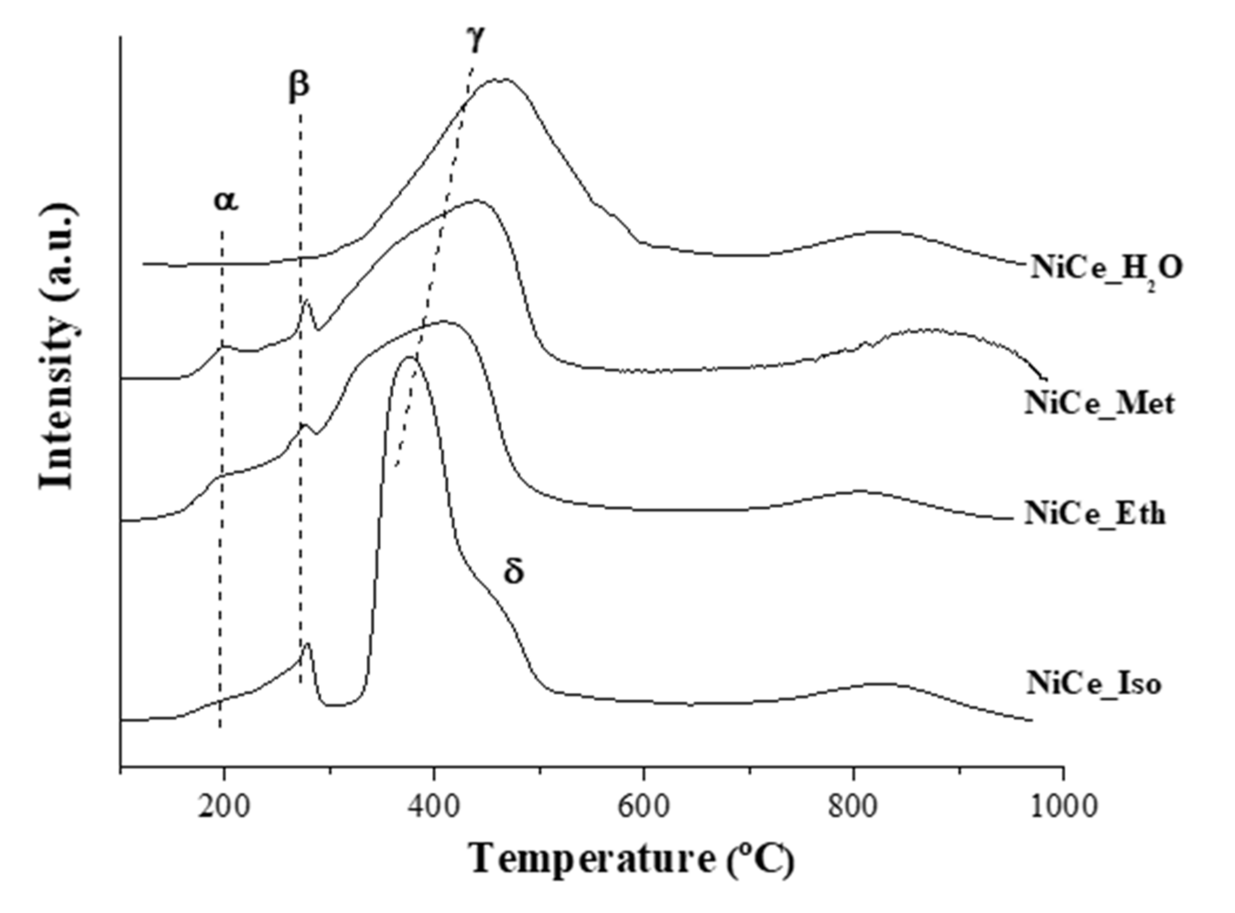
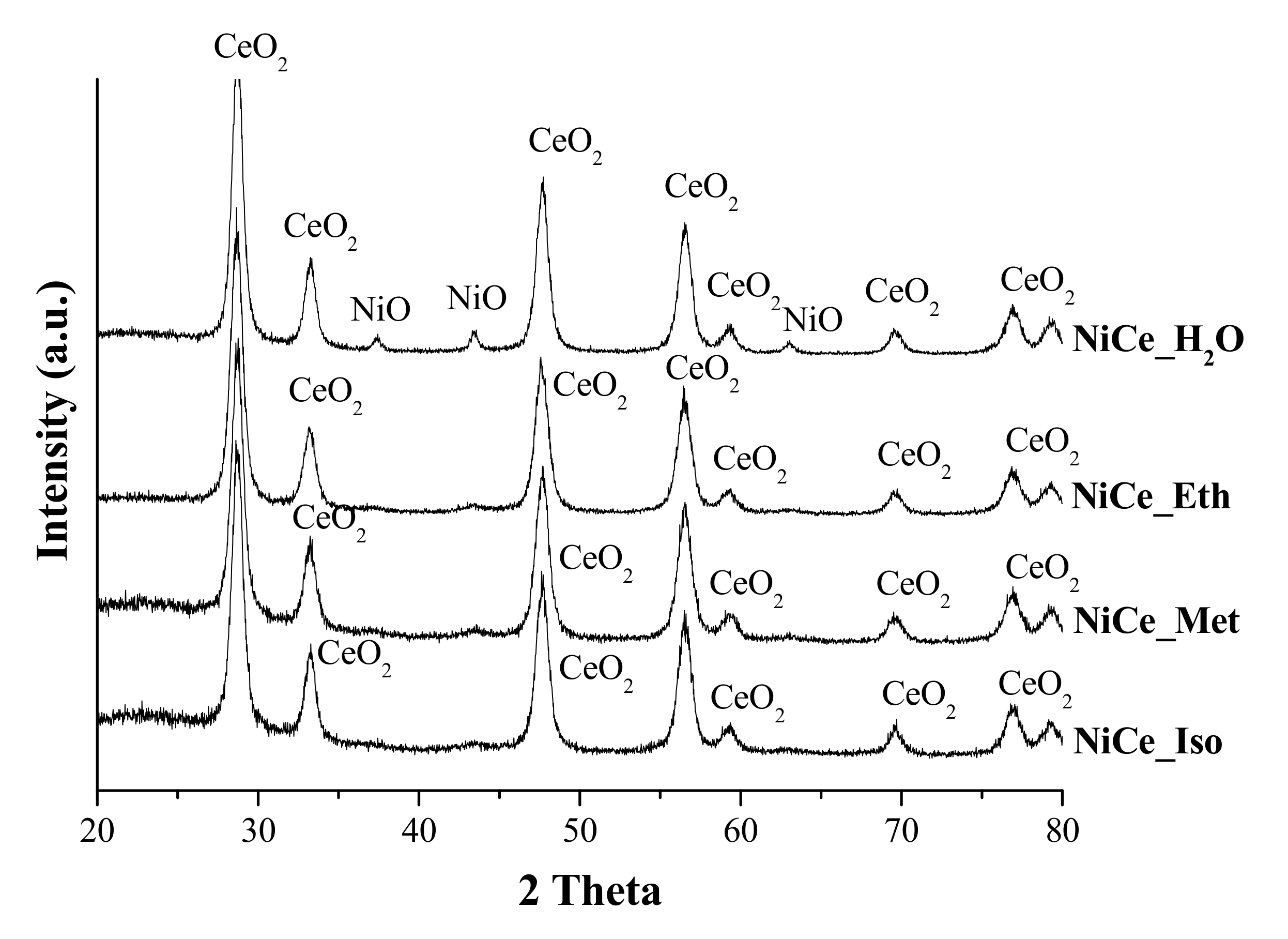
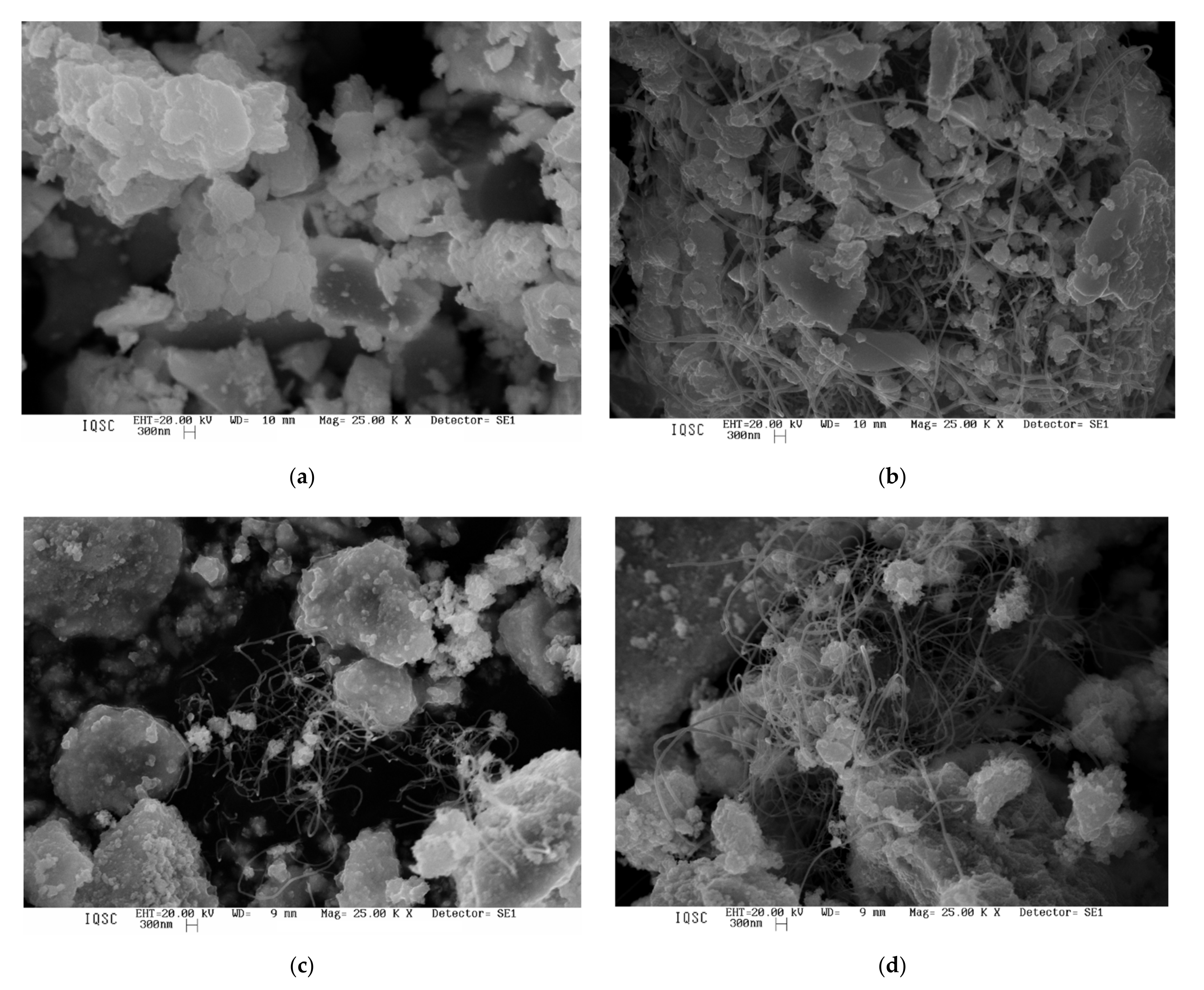
3.1. Characterization of Catalysts

The results of X-ray diffraction analysis (XRD) of the catalysts are shown in Figure 1. These results indicate that there is no noticeable difference in the crystallographic patterns of the catalysts synthesized by coprecipitation method using various alcohols (NiCe_Met, NiCe_Eth, and NiCe_Iso), all peaks of XRD patterns of these samples correspond to CeO2 (JCPDS 81-0792; with a face-centered cubic structure present in the catalysts). Moreover, there are no peaks related to the crystal phase of NiO in the XRD patterns; meaning that the crystal structure of NiO species is too small to be detected by XRD. However, the peaks related to NiO (face-centered cubic centered; JCPDS 78-0643) can be observed in the catalyst prepared by coprecipitation in water (NiCe_H2O), despite these peaks are of low intensity.
Table 1 shows the average crystallite sizes (nm) of each catalyst, calculated by the Scherrer Equation (with the data obtained by the DRX patterns) [16]. The values show that the crystallites of CeO2 of the catalysts prepared in alcohols are smaller than the CeO2 crystallite of the catalyst prepared in the presence of water. There was not a defined trend of the crystallite sizes among the samples obtained in different alcohols. The catalysts prepared in water have NiO crystallites of 14 nm.
At this point, we must mention, that during the co-precipitation method, before the total precipitation of the catalyst precursors, cations Ni2+ and Ce4+ are present in solution, and the interactions of these ions with water correspond to the ion-dipole interaction. The ion-dipole interactions between cations Ni2+ and Ce4+ and the molecules of alcohols are less intense due to the increase in the non-polar part of each alcohol molecule (decreasing order of polarity: water > methanol > ethanol > isopropanol) [17]. It is possible that such interaction could be influencing the rate at which the hydroxides formed by these cations get together to form the first clusters, which later form grains, polymers, and subsequently the precipitated gel. This gel gives rise to polycrystalline structures. The less intense ion-dipole interactions could decrease the grain growth rate and later stages; leading to the obtainment of crystallites of smaller size (which is desirable in catalysis). The average crystallite size values are shown in Table 1 support this hypothesis.
The elemental composition obtained by EDX analysis for each catalyst is present in Table 1. These values are very close to the theoretical composition (10% nickel in each catalyst, regarding the total weight of the catalyst). The surface area values (also presented in Table 1) are in agreement with the expected: higher surface areas were obtained by the catalysts obtained in the alcohols (methanol, ethanol, and isopropanol), the catalyst prepared in water recorded the lowest surface area value. This indicates that smaller crystallites (present in samples obtained with alcohol) led to the formation of larger surface areas.
Figure 2 shows the profiles obtained by H2-TPR analyzes of catalysts. Two different regions can be observed: the first, located at temperatures below 570 °C, is associated with the reduction of NiO (NiO + H2 → Ni° + H2O), and the second, located at higher temperatures, is due to reduction of the catalytic support (CeO2). These results show that the use of alcohols during the preparation method influenced the reduction profiles because various NiO species in different interactions with the support were formed, these NiO species can be observed in different regions below 570 °C of the H2-TPR profiles (see peaks α, β, γ, and δ). The term NiO species refers to NiO clusters located in different parts of the CeO2 support. Their location can influence their interactions (strong interactions or weak interactions), these interactions can also be an expression of the chemical affinities between oxides (example: in some cases the tendency to form solid solution). Hence the term NiO species in different interactions with the catalytic support.
According to these profiles, the NiCe_H2O catalyst forms a single broad peak of NiO (γ peak) at a range of 300–570 °C; this indicates that there is a single type of NiO species interacting with CeO2 when the co-precipitation method occurs in the presence of water. On the other hand, NiCe_Met and NiCe_Eth led to the formation of different NiO species (three types of NiO species: α, β, and γ), the profiles are very similar between these two catalysts. The H2-TPR profile of NiCe_Iso presents a greater difference since it presents up to four NiO species (α, β, γ, and δ). All these NiO species are in the temperature range between 200 and 570 °C. The H2-TPR profiles indicate that the co-precipitation in the different alcohols led to the formation of various NiO species in different interactions with the CeO2 catalytic support. Similarly to that affirmed in the XRD discussion, these results suggest that the polarity of the solvents (water > methanol > ethanol > isopropanol) influenced the formation of NiO species on the surface of the catalyst; in this case, the use of methanol, ethanol, and isopropanol favored the formation of NiO species interacting in different manners with the catalytic support (CeO2).
The two reduction peaks related to CeO2 are well known in the literature [18,19]: the first peak located around 570 °C is associated with a reduction of the CeO2 surface oxygen, the second at 890 °C can be attributed to the reduction of bulk part of CeO2, which occurs by the removal of O2 anions from the reticulum and the formation of Ce2O3 (by 2CeO2 + H2 → Ce2O3 + H2O). These two peaks were present in the profiles of the support and the catalysts.

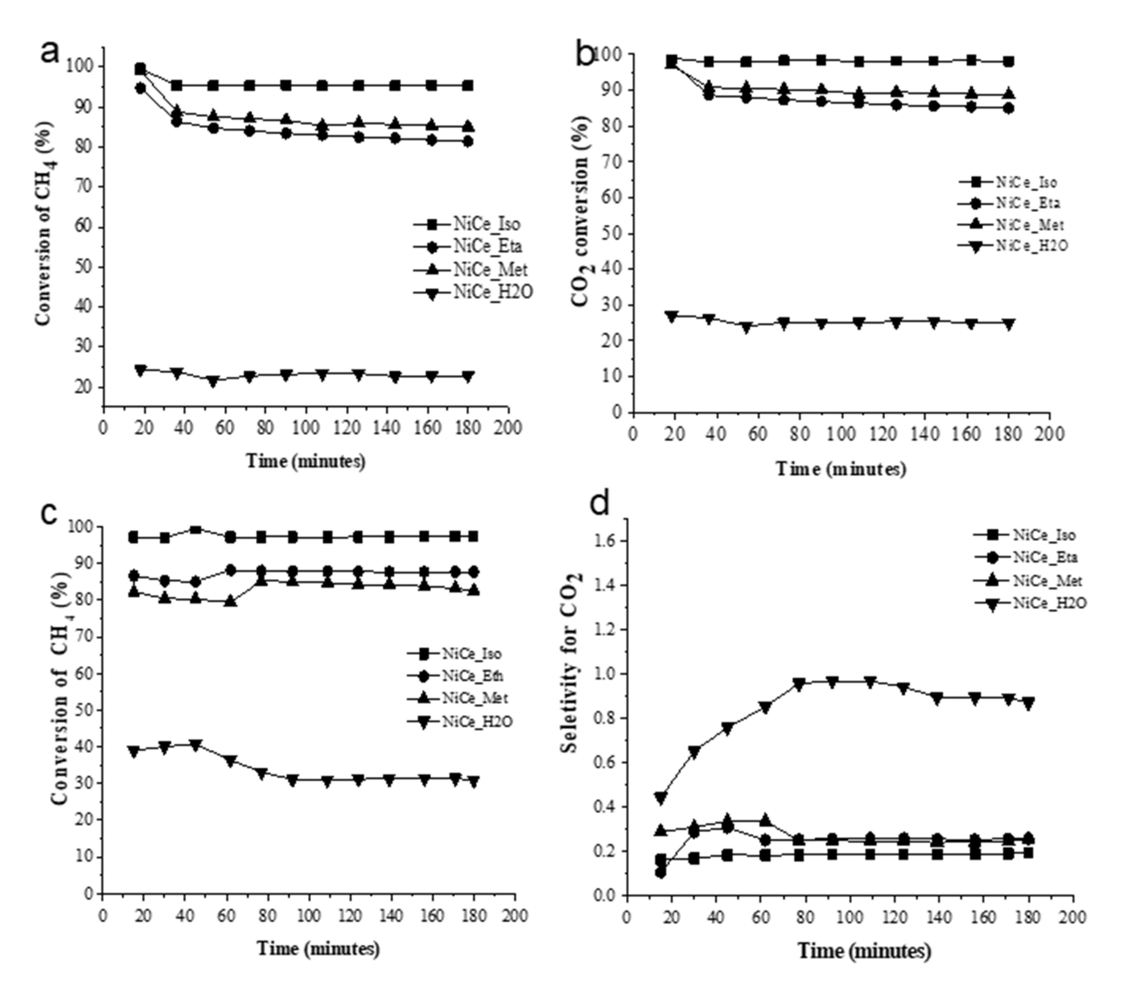
3.2. Catalytic Tests

Figure 3a shows the conversion profiles of methane (%) during the ORM. The catalytic tests indicate that the use of alcohols in the preparation method of the catalysts was favorable for the catalysis of this reaction, and it favored the formation of active Niº centers on the surface of the material to break the C-H bond of methane, thus leading to high conversion values. As can be observed in Figure 3a, the NiCe_Eth and NiCe_Met catalysts exhibit very similar catalytic behavior, this could be related to the corresponding characterization results, as they recorded very similar H2-TPR profiles (Figure 2), crystallite sizes, and surface area values (Table 1). On the other hand, the best alcohol among those studied in this study is isopropanol, which made the corresponding catalyst (NiCe_Iso) achieve the highest conversion values among all catalysts. Its superior catalytic activity regarding the other catalysts could be related to the formation of various NiO species in different interactions with the catalytic support (CeO2) (observed by H2-TPR reduction profile, Figure 2), its largest surface area (the largest recorded: 46 m2·g−1), and its small crystallite size (when compared to the catalyst synthesized in water). The worst catalytic performance was obtained by that synthesized in water (NiCe_H2O). The carbon deposition rates were: 0.05 (NiCe_H2O); 0.12 (NiCe_Met); 0.13 (NiCe_Eth), 0.15 (NiCe_Iso) mmolC·h−1, that are in agreement with the increasing order of CH4 conversion %. After the tests of ORM, traces of water were collected (as a by-product), thus showing the occurrence of the Reverse of WGSR reaction (CO2 + H2 ↔ CO + H2O) in parallel. This could explain the reason why the CO2 conversion % is superior to the CH4 conversion %, over every catalyst (Figure 3b).
The % conversion profiles on the catalysts in POM were similar to ORM and are shown in Figure 3c; additionally, the water collected during the POM reaction indicated that this reaction occurred by the Indirect Methane Combustion-Reforming mechanism (reactions 5, 2, 1), where the Total Combustion of Methane (TCM) produces CO2 and H2O (as primary products), and is followed by Dry Reforming of Methane (DRM) and Steam Methane Reforming (SMR) [1,20,21]:
TCM :   CH 4 + 2 O 2     CO 2 + 2 H 2 O   Δ H 298 K 0 = 890   kJ · mol 1
The global sum of reactions (5) + (2) + 2×(1) is the reaction (3), with H2/CO ratio = 2. Moreover, in the presence of CO2 and H2 in the products, the reverse water-gas shift reaction (RWGSR) (6) is very likely to occur (the reaction is favored at high temperature):
RWGSR :   CO 2 + H 2 CO + H 2 O   Δ H 298 K 0 = 41   kJ · mol 1
Figure 3d shows the data for selectivity for CO2 obtained during POM, according to which, the worst catalyst (NiCe_H2O) favored a greater selectivity for CO2 (unwanted product). The NiCe_H2O catalyst had a low catalytic activity, and low stability within the reaction time. The carbon deposition in POM rates were: 0.03 (NiCe_H2O); 0.09 (NiCe_Met); 0.10 (NiCe_Eth), 0.12 (NiCe_Iso) mmolC·h−1, that are in agreement with the increasing order of CH4 conversion %.
Figure 4 shows the SEM images of the catalysts after the ORM reaction. According to these images, the use of alcohols (in the preparation method of the catalysts) favored the formation of filamentous carbon, whereas the catalyst prepared in water favored the formation of amorphous carbon on the surface catalysts, this amorphous carbon could be related to the low catalytic performance recorded by the NiCe_H2O catalyst.
The formation of carbon deposits during hydrogen production by methane reforming reactions is almost inevitable. One type of carbon is filamentary carbon (often associated with whisker carbon). In this case, Ni° particles act as a catalyst at the tip of the filament, thus explaining the activity and stability of the NiCe_Eth, NiCe_Met, and NiCe_Iso catalysts during the reaction [22].
On the other hand, it seems that the formation of amorphous carbon affected the performance of the NiCe_H2O, which probably blocked the pores and encapsulated the active sites of Ni° [23].

4. Conclusions

The use of alcohols (methanol, ethanol, isopropanol) during the preparation of the Ni/CeO2 catalysts by the co-precipitation method markedly modified the chemical characteristics of the material that led to good catalytic performances in POM and ORM reactions. The characteristics such as crystallite size (nm), surface area (m2·g−1), reduction profile (H2-TPR), obtained by the use of these alcohols during the preparation method improved the catalytic performance of the Ni/CeO2 catalysts in both reactions. The best solvent among those studied was Isopropanol. The use of alcohols (methanol, ethanol, isopropanol) led to the formation of filamentous carbon in the catalyst after the ORM reaction.
The water-synthesized catalyst proved to be poorly efficient in POM and ORM and led to the formation of amorphous carbon after the ORM reaction.

Author Contributions

Conceptualization, Y.J.O.A., K.F.M.E. and A.d.Z.; methodology, Y.J.O.A., K.F.M.E. and A.d.Z.; formal analysis, Y.J.O.A.; investigation, Y.J.O.A.; writing—original draft preparation, Y.J.O.A.; writing—review and editing, Y.J.O.A.; supervision, E.M.A. and Y.J.O.A.; funding acquisition, Y.J.O.A. and E.M.A. All authors have read and agreed to the published version of the manuscript.

Funding

The São Paulo Research Foundation (FAPESP) for the financial support (Grant N°: 2014/24940-5), and the Brazilian National Council for Scientific Development (CNPq, Grant N° 407097/20).

Institutional Review Board Statement

Not applicable.

Informed Consent Statement

Not applicable.

Data Availability Statement

Not applicable.

Acknowledgments

The authors thank the São Paulo Research Foundation (FAPESP) for the financial support (Grant N°: 2014/24940-5), and the Brazilian National Council for Scientific Development (CNPq, Grant N° 407097/20).

Conflicts of Interest

The authors declare no conflict of interest.

References

  1. Asencios, Y.J.O.; Assaf, E.M. Synthesis of NiO/Y2O3/ZrO2 Catalysts Prepared by One-Step Polymerization Method and Their Use in the Syngas Production from Methane. Int. J. Chem. Eng. 2018, 2018, 9487486. [Google Scholar] [CrossRef]
  2. Carvalho, F.L.S.; Asencios, Y.J.O.; Bellido, J.D.A.; Assaf, E.M. Bio-Ethanol Steam Reforming for Hydrogen Production over Co3O4/CeO2 Catalysts Synthesized by One-Step Polymerization Method. Fuel Process. Technol. 2016, 142, 182–191. [Google Scholar] [CrossRef]
  3. Asencios, Y.J.O.; Elias, K.F.M.; Assaf, E.M. Oxidative-Reforming of Model Biogas over NiO/Al2O3 Catalysts: The Influence of the Variation of Support Synthesis Conditions. Appl. Surf. Sci. 2014, 317, 350–359. [Google Scholar] [CrossRef]
  4. Asencios, Y.J.O.; Rodella, C.B.; Assaf, E.M. Oxidative Reforming of Model Biogas over NiO-Y2O3-ZrO2 Catalysts. Appl. Catal. B Environ. 2013, 132–133, 1–12. [Google Scholar] [CrossRef]
  5. Raju, A.S.K.; Park, C.S.; Norbeck, J.M. Synthesis Gas Production Using Steam Hydrogasification and Steam Reforming. Fuel Process. Technol. 2009, 90, 330–336. [Google Scholar] [CrossRef]
  6. Bradford, M.C.J.; Vannice, M.A. Catalytic Reforming of Methane with Carbon Dioxide over Nickel Catalysts I. Catalyst Characterization and Activity. Appl. Catal. A Gen. 1996, 142, 73–96. [Google Scholar] [CrossRef]
  7. Zawadzki, A.; Bellido, J.D.A.; Lucrédio, A.F.; Assaf, E.M. Dry Reforming of Ethanol over Supported Ni Catalysts Prepared by Impregnation with Methanolic Solution. Fuel Process. Technol. 2014, 128, 432–440. [Google Scholar] [CrossRef]
  8. Lucredio, A.F.; Bellido, J.D.A.; Zawadzki, A.; Assaf, E.M. Co Catalysts Supported on SiO2 and γ-Al2O3 Applied to Ethanol Steam Reforming: Effect of the Solvent Used in the Catalyst Preparation Method. Fuel 2011, 90, 1424–1430. [Google Scholar] [CrossRef]
  9. Ho, S.W.; Su, Y.S. Effects of Ethanol Impregnation on the Properties of Silica-Supported Cobalt Catalysts. J. Catal. 1997, 168, 51–59. [Google Scholar] [CrossRef]
  10. Asencios, Y.J.O.; Nascente, P.A.P.; Assaf, E.M. Partial Oxidation of Methane on NiO-MgO-ZrO2 Catalysts. Fuel 2012, 97, 630–637. [Google Scholar] [CrossRef]
  11. Asencios, Y.J.O.; Assaf, E.M. Combination of Dry Reforming and Partial Oxidation of Methane on NiO-MgO-ZrO2 Catalyst: Effect of Nickel Content. Fuel Process. Technol. 2013, 106, 247–252. [Google Scholar] [CrossRef]
  12. Lucrédio, A.F.; Filho, G.T.; Assaf, E.M. Co/Mg/Al Hydrotalcite-Type Precursor, Promoted with La and Ce, Studied by XPS and Applied to Methane Steam Reforming Reactions. Appl. Surf. Sci. 2009, 255, 5851–5856. [Google Scholar] [CrossRef]
  13. Lucrédio, A.F.; Assaf, J.M.; Assaf, E.M. Methane Conversion Reactions on Ni Catalysts Promoted with Rh: Influence of Support. Appl. Catal. A Gen. 2011, 400, 156–165. [Google Scholar] [CrossRef]
  14. Song, H.; Ozkan, U.S. The Role of Impregnation Medium on the Activity of Ceria-Supported Cobalt Catalysts for Ethanol Steam Reforming. J. Mol. Catal. A Chem. 2010, 318, 21–29. [Google Scholar] [CrossRef]
  15. Shelepova, E.; Vedyagin, A.; Sadykov, V.; Mezentseva, N.; Fedorova, Y.; Smorygo, O.; Klenov, O.; Mishakov, L. Theoretical and experimental study of methane partial oxidation to syngas in catalytic membrane reactor with asymmetric oxygen-permeable membrane. Catal. Today 2016, 268, 103–110. [Google Scholar] [CrossRef]
  16. Chien, S.H.; Chiang, W.L. Catalytic Properties of NiX Zeolites in the Presence of Ceriumadditives. Appl. Catal. 1990, 61, 45–61. [Google Scholar] [CrossRef]
  17. Atkins, P.; Jones, L. Princípios de Química: Questionando a Vida Moderna e o Meio Ambiente; Bookman Editora: Porto Alegre, Brazil, 2006. [Google Scholar]
  18. Wang, H.; Ye, J.L.; Liu, Y.; Li, Y.D.; Qin, Y.N. Steam Reforming of Ethanol over Co3O4/CeO2 Catalysts Prepared by Different Methods. Catal. Today 2007, 129, 305–312. [Google Scholar] [CrossRef]
  19. Yao, H.C.; Yao, Y.F.Y. Ceria in Automotive Exhaust Catalysts. I. Oxygen Storage. J. Catal. 1984, 86, 254–265. [Google Scholar] [CrossRef]
  20. York, A.P.E.; Xiao, T.; Green, M.L.H. Brief Overview of the Partial Oxidation of Methane to Synthesis Gas. Top. Catal. 2003, 22, 345–358. [Google Scholar] [CrossRef]
  21. Asencios, Y.J.O.; Bellido, J.D.A.; Assaf, E.M. Synthesis of NiO-MgO-ZrO2 Catalysts and Their Performance in Reforming of Model Biogas. Appl. Catal. A Gen. 2011, 397, 138–144. [Google Scholar] [CrossRef]
  22. Uchida, H.; Harada, M.R. Chapter 5—Hydrogen Energy Engineering Applications and Products. In Science and Engineering of Hydrogen-Based Energy Technologies: Hydrogen Production and Practical Applications in Energy Generation; Academic Press: Cambridge, MA, USA, 2018; pp. 201–220. [Google Scholar]
  23. Gamal, A.; Eid, K.; El-Naas, M.H.; Kumar, D.; Kumar, A. Catalytic Methane Decomposition to Carbon Nanostructures and COx-Free Hydrogen: A Mini-Review. Nanomaterials 2021, 11, 1226. [Google Scholar] [CrossRef]
Figure 1. XRD patterns of the catalysts.
Methane 01 00007 g001
Figure 2. H2-TPR profiles of the catalysts.
Methane 01 00007 g002
Figure 3. Catalytic tests Results for the Oxidative Reforming of Methane (ORM; (a,b)) and the Partial Oxidation of Methane (POM; (c,d)).
Methane 01 00007 g003
Figure 4. Images obtained by Scanning Electron Microscopy, SEM (25,000×) after the ORM reaction: NiCe_H2O (a), NiCe_Met (b), NiCe_Eth (c), and NiCe_Iso (d).
Methane 01 00007 g004
Table 1. The elemental composition obtained by EDX for the catalysts (Average values), BET surface area, and average crystallite size of the catalysts (obtained by Scherrer equation).
CatalystSurface Area
(m2·g−1)
%Ni (wt.%)
(EDX)
Average Crystallite Size (nm)
CeO2NiO
NiCe_met239.18-
NiCe_eth219.18-
NiCe_iso469.410-
NiCe_H2O58.71214
Publisher’s Note: MDPI stays neutral with regard to jurisdictional claims in published maps and institutional affiliations.

