Article

Floater Assembly and Turbine Integration Strategy for Floating Offshore Wind Energy: Considerations and Recommendations

1
Department of Engineering Science and Ocean Engineering, National Taiwan University, Taipei 10617, Taiwan
2
Energy Research Center, National Taiwan University, Taipei 10617, Taiwan
*
Author to whom correspondence should be addressed.
Wind 2024, 4(4), 376-394; https://doi.org/10.3390/wind4040019
Submission received: 20 September 2024 / Revised: 8 November 2024 / Accepted: 15 November 2024 / Published: 21 November 2024

Abstract

The increasing demand for cost-effective floating offshore wind turbines (FOWTs) necessitates streamlined mass production and efficient assembly strategies. This research investigates the assembly and integration of 15 MW FOWT floaters, utilising a semi-submersible floater equipped with a 15 MW wind turbine. The infrastructure and existing port facilities of Taiwan are used as an example. The effectiveness of various assembly and integration strategies has been evaluated. The study outlines equipment and infrastructure requirements for on-quay floater and turbine assembly, comparing on-quay assembly to construction at remote locations and subsequent towing. Detailed analyses of port operations, crane specifications, and assembly procedures are presented, emphasising the critical role of crane selection and configuration. The findings indicate that on-quay assembly at one major port is feasible and cost-effective, provided that port infrastructure and operational logistics are optimised. This research offers insights and recommendations for implementing large-scale FOWT projects, contributing to advancing offshore wind energy deployment.

Graphical Abstract

1. Introduction—Finding the Best Construction Strategy

For some countries without shallow water, floating wind in deep water is the only way to generate a substantial amount of wind energy. Unfortunately, at the moment, floating wind is much more expensive than fixed-bottom offshore wind, particularly due to mass floater production and supply chain challenges [1]. To achieve cost reductions in line with fixed offshore wind, streamlining the mass production and installation of FOWTs (floating offshore wind turbines) is necessary.
Hong et al. [2] made a broad overview of FOWT farm installation challenges and opportunities. They emphasized challenges such as the increasing difficulty of turbine–floater mating (integration), the necessity for installation vessels’ fleet expansion and the refinement of cost estimation models, making use of weather and environmental data. They also identified opportunities for improvement, such as the potential for technological advancements to simplify the integration process and the use of data-driven models to enhance cost estimation accuracy.
Torres et al. [3] compared FOWT installation strategies for three different integration ports in the UK, highlighting the strong influence that port choice exerts on project cost and execution time. Notably, he explored the influence of foreign manufacturing and floater towing time on the project.
The floater assembly and turbine integration concepts were touched upon by Diaz and Soares [4]; they produced a tool for an economic view of the logistics and installation involved in a FOWT farm design with a TLP (tension-leg platform) floater farm as a case study. They identified numerous parameters as inputs for the tool, including crane capacity, quay space, cable length, etc., providing a good point for comparison. BVG Associates produced a large report, calculating in-detail components and process costs for the whole FOWT farm lifecycle, albeit only for a single strategy [5].
Floater construction cost is recognised as a paramount optimisation objective in many studies. In most cases, it is assumed that the floater is constructed at one location from parts as small as individual sheets and girders; such studies do a good job finding the floater dimensions with lowest manufacturing costs, considering the length of the welding seams, painting and administration cost [6,7]. However, a recent development in the industry is modular fabrication, where parts and floater production are separate, which allows to outsource cheap components such as a single column or pontoon; thus, final assembly and transportation emerge as major costs and are investigated in this paper. The cost relationships derived in this paper could be included in the multi-variable optimisation framework like the one by Zhou et al. [6].
Previous studies focused on optimising a single floater structural design and mooring system [8,9,10,11], which will be used as a baseline for this study. The port requirements commonly mentioned in the literature [4,5] are quay bearing capacity, crane reach and lifting capacity. This study provides these numbers for a hypothetical 100-floater farm based on the TaidaFloat semi-submersible floater [9,12] equipped with NREL’s IEA 15 MW wind turbine [13].
There are two possible approaches to studying FOWT port operations: use an existing port and tailor operations to its constraints or devise a perfect port for the most effective operations. Port construction is an immense capital investment, and construction and planning take more than a decade, including planning for FOWT and other types of operations (cargo, passenger and military). Given that, it was decided to focus on an existing port and compare how different installation strategies would affect the requirements.
As the wind farm will be in the Taiwan Strait, Taichung Port has been chosen for the study. Taichung is one of Taiwan’s only two industrial-use harbours without height restrictions due to nearby airports, which ban 15 MW turbines from being installed in other harbours for aeroplane safety reasons (the other being Xingda Harbour). The government of Taiwan has already designated Taichung as an offshore wind port, and it is undergoing an expansion to provide a safe harbour for FOWTs and other industrial projects, which includes two new quays directly facing the Taiwan Strait and a wave breaker, seen in Figure 1 [14]. Interior quays (those inside the port) currently used for fixed-bottom wind marshalling will not be available for FOWT floaters due to the collision risk of marine traffic. The two new quays will be leased independently to two developers. This study investigates whether the two quay’s space could be used effectively compared to other alternatives.
Several strategies were researched and compared in regard to the floater’s construction/assembly and turbine integration. One key conclusion is that floater on-quay assembly in Taichung would be more cost-effective than the construction and towing from a drydock in Kaohsiung or other remote places.

2. Port Operations and Crane Types

Table 1 lists the complete list of possible port operations needed for a FOWT project and the necessary equipment. Not all operations are expected to be done in the same port; a port is classified depending on which operations are done in it. Theoretically, all these functions could be separated into different ports. A few concepts have been proposed:
  • Floater—floater hull assembly port;
  • Turbine—turbine integration port;
  • F+T—floater assembly and turbine integration port;
  • Moor—mooring and service base port;
  • All—all-in-one hub port.
The floater, turbine and mooring components for 15 MW FOWT are all large in size and heavy in weight, so, usually, the only viable shipping strategy is by sea; therefore, all of the concepts above need at least a deep enough quay and a crane for loading/offloading operations; however, locally produced components might not need that. This study assumes that floater components are fabricated elsewhere; alternative ways are local manufacturing or delivery in pre-assembled blocks.
Table 1. Port classifications based on capabilities of operation types for a FOWT project.
FloaterTurbineF + TMooringAllOperation TypesQuay Depth, mCrane Capacity, tStorage, km2
Components offloading4–10<10000.02
Turbine assembly-<16000.03
Turbine integration8–12<32000.05
Turbine comp. storage--0.06
Floater comp. storage--0.2
Floater assembly-<16000.03
Floater launch8–12-0.02
Mooring comp. storage-<2000.04
Anchor Handling Base4–8<200-
Service Vessel base4–8<200-
Spare parts storage-<2000.04
For all the lifting operations involved, cranes are the critical tools. For this study, they are defined in Figure 2. While small and medium cranes can be procured relatively easily, procuring, installing and operating a large crane (i.e., ring crane) is challenging. Therefore, the latter is discussed in detail here. The large crane may perform heavy lifts during floater assembly, turbine installation and unloading vessels with incoming equipment. When selecting a crane, not only the lifting capacity needs to be checked but also the reaching range for a particular component’s weight as defined in crane curves.
For example, the CC9800 crane [16] has a 1600 t lift capacity and 228 maximum height, but upon a close investigation of its specification, at 150 m (nacelle height), it can only lift 355 t. Thus, it is not suitable for nacelle lift. LR 11,350 was chosen in the Taichung Harbour improvement study of 2016 [14]. LR 11,000, LR 11,350, LR 12,500 and LR 13,000 [17] lifting tables were analysed, and only LR 12,500 [18] was found suitable for a 15 MW nacelle lift (configuration H90 W54 B2). It is noted that, without a detailed lifting table analysis, suitability cannot be judged just on maximum capacity, an erroneous assumption often made in the literature.
The PTC200-DS mega crane is selected for this study as one of its variants. The mega crane (also known as ring crane) had already been employed recently in a nearby harbour in Taiwan [19] for lifting jacket foundations. It has sufficient lift capacity to lift a 15 MW nacelle to 150–165 m hub height. It has several configurations of boom and jib length, specification details of the weights that can be lifted at different heights and horizontal reach radii [20]. In this paper, it is expected that all the operations will be completed by only one main crane, sometimes with the help of a small or medium auxiliary crane. Therefore, the crane should be fit for all operations. One of the most significant constraints from offshore wind experience is the nacelle lift, where height, reach and weight are all pushed to the limit. Due to this requirement, only the maximum boom length configurations are considered, and different jib lengths allow balancing between the required maximum weight, height and reach, as illustrated in Figure 3. All the liftable components’ weights are compiled in Table 2 to determine which jib length is suitable. The corresponding reach radius for three different jibs is found in the crane specs [20].
A project-specific crane working zone could be developed based on specific floater, turbine and crane configurations, such as the one shown in Figure 3. Circular bands co-centred with the crane show what components can be lifted. For example, the blades and bracing are relatively lighter and can be lifted with the furthest reach, giving zone B. The zones are cumulative, so liftable components in a zone can also be lifted in the zones of smaller radii (e.g., blades can be lifted in any zone). However, there is a dead eye zone near the crane where no lifts can be performed.
As a ring crane cannot be moved and changing configuration is very time-consuming and expensive, a suitable configuration must be chosen to handle floater assembly, turbine integration and components lifts. Therefore, the quay, assembly site and temporary storage areas must be organised inside the corresponding zones.
Different jibs are compared to determine the most suitable for the operations described in Part 3. Out of the crane specification, three jib lengths were suitable to perform all operations: 106, 101 and 89 metres. It is evident from Figure 3 that longer jibs have a farther reach, which is beneficial, but smaller heavy load bands and larger dead zones are detrimental. An unsuccessful attempt was made to optimise the floater assembly strategy by choosing a smaller jib length. Finally, the longest suitable jib (106 m) is chosen, as it allows a larger total working zone, making it easier to access stored components.

3. Floater Block Assembly and Launching

Next, typical installation procedures are devised, starting with floater block assembly and launch. This is based on the assumption that Taichung Port would be the site for assembly and integration. The most challenging part of the procedure is to launch the assembled floater on the water after block assembly. Five methods are shown in Figure 4. Drydock and semi-sub HLV (heavy lift vessel) are considered more practical among the five.
Drydock was used for those semi-submersible platforms for the WindFloat Kincardine and Atlantic projects; however, after the parts are assembled, the floater cannot moved, for example, for on-quay dry storage; thus, it is one-way launching. As drydocks are from the shipbuilding industry, they are made very long and narrow to accommodate ships—very few docks are able to accommodate wide floaters (±100 m for 15 MW); if the width is enough, a batch of several floaters must be placed in it to take up the remaining length; the dock door cannot be opened until all floaters have been completed; thus, one-by-one delivery is not possible.
Taichung Port does not have such a large infrastructure, i.e., dry dock, slide or lift. Also, a 5448-ton floater cannot be lifted by any existing port crane. The best method may be a semi-submersible barge (e.g., a floating dock), which has been used many times in the oil and gas industry. When using this method, the port depth is critical, as it must accommodate the floater hull (5 m) and the HLV (2–6 m) draft. However, other solutions are available to utilise the existing infrastructures in Kaohsiung or Taipei Port. A wet tow of the floater to Taichung would be required, which may take two to four days.
Figure 5 shows the quayside block assembly method of the TaidaFloat using a ring crane and SPMTs (self-propelled modular transporters) [21]. The four steps are explained below. The main column is positioned closer to the crane, as the crane can only handle its heavy weight in a particular range (dark green), as explained in Figure 3 and Table 2. The far side column cannot be too far from the crane (light green). With these constraints, the only possible floater position during assembly is shown in Figure 3. This implies that the pontoon closest to the crane must be installed with SPMTs, as it is in its blind zone.
Step 1: The first pontoon support blocks are installed, then the first pontoon is placed on blocks using SPMTs.
Step 2: The other support blocks should be correctly placed based on the actual location. The remaining two pontoons are installed with the ring crane. After alignment is confirmed, the pontoons are welded together.
Step 3: The three columns are installed with a ring crane and an auxiliary crane (for upending columns to a vertical position). The columns were welded to the pontoons.
Step 4: Lift one brace with the main crane, weld to the columns and repeat for the other two braces.
The complete list of assembly steps is shown in Table 3; it is assumed that (i) water tightness tests and (ii) non-destructive weld tests are performed in parallel with the next component assembly. Electro gas manual welding is used, as this is a quay environment, and many seams are vertical or slanted. The time for welding operations varies due to the thickness of the metal and is calculated according to Table 4, adapted from [22]. The time for lifting operations was approximated from [23]. A Gantt chart was made, and manpower was identified as a bottleneck. Even though some operations, such as installing the columns, can be performed in parallel, changing the number of skilled workers (welders) during the installation is impractical due to logistical and contractual reasons. Assuming one team of six works for one 8-h shift a day, two teams could assemble the floater in 77 days or three teams in 51 days, which could be impractical due to third-shift working time during the night. The paper assumes no weekends or holiday breaks, which is true for many Asian enterprises. This may be achieved by hiring more part-time employees, but this is not always the case in real life. It should be noted that there are some floater designs [24,25] that promise fast assembly without welding. However, they have not been tested yet, and most floaters have historically been welded.
Skilled welders are in shortage in Taiwan [26,27]; thus, foreign teams are invited for the whole project duration; such teams usually comprise about six members. If the crane for assembly is rented on a daily basis, crane idle time is of concern. Construction and idle time can be reduced by performing multiple assemblies in parallel. However, an even more significant concern arises: how often a new set of parts can be delivered for assembly. The minimum total time and idle time can be achieved by using many welders in a perfect situation. However, if 11 teams are used (which could prove impossible to hire), new parts must be delivered each week, which might also be unrealistic. More realistic options are procuring a new set of parts every two weeks (36 welders) or three weeks (24 welders).
After assembly, there are two options:
  • The floater will be transported to a semi-submersible barge and lowered to the water, then moored at the quayside and the turbine installed.
  • The turbine will be installed on the floater onshore, and the assembly will be moved to a barge and lowered to the water.
Option 2 allows much easier turbine integration, as the floater and crane are not moving at all, no mooring is needed and electricity is easily supplied to the turbine for hub rotation. However, if the turbine is installed first, the SMPTs and supports below the main column must withstand the turbine weight and the floater. Also, the crane would need ±30 m of extra lift height (floater height). Additionally, lowering the weight of the barge will lead to deeper draught, which is limited. Overall, Option 1 may be more practical.
Block support configuration was based on the existing projects. Considering SPMT handling, the main column and pontoon under it (20% of pontoon weight) are supported by 17 blocks with a total area of 38.59 m2. In Option 1, these blocks will support 1092 t, requiring a quay bearing capacity of 28.3 t/m2. Option 2 supports 3370 t, requiring 87.3 t/m2 capacity. Some upper-end standards require quays to be built for 30 t/m2 capacity, making Option 1 viable, while Option 2 is not. Therefore, it is not investigated further. While supporting the column with SMPTs could increase the supported area, the floater would still have to rest on blocks when submerged on a barge. Unfortunately, the Taichung Harbour improvement study of 2016 [14] recommended only 15 t/m2.

4. Cranes for Turbine Assembly

After launching, the next step is to install the turbine on the floater using cranes. First, the floater must be moored to the quay to minimise the wave-induced motions; note that there will be some movement, so this operation introduces a weather constraint. Alternatively, it can be ballasted to sit on the quay if the seabed surface is flat and the floater structure fits.
Then, there are a few ways to install the turbine [28]—the three-part tower lift is chosen due to the weight of the turbine tower for floating wind, then the nacelle is lifted separately due to its weight and the blades will be installed one by one with an electrical cable connected to rotate the hub.
The turbine can be placed in the central or out-of-centre (side) column of a semi-submersible floater. It is sometimes reasoned that the side turbine location allows smaller-capacity cranes to be used for turbine integration, which is critical, as large cranes are in short supply. In contrast, the central turbine location allows hull weight reductions due to improved stability and turbine load distribution. However, Table 2 showed that, due to the crane jib’s moment capacity, a very large crane is needed even for side-column configuration; this kind of crane is enough to install the turbine in both central (marked C in Figure 3) and side locations. How close the crane can be positioned to the quayside is also a factor, but the usual clearance of 5–10 m is not a problem for 3200 t cranes. This giant crane on-site can also handle the floater on-quay assembly, as shown in Figure 5. Overall, having a large crane is the best decision. However, a side column arrangement could help if the large crane is impossible to procure due to supply chain constraints. Then, a tandem of two smaller crawler cranes could install the turbine, as with the 15 MW onshore prototype [29].
Thus, the crane cost is important in determining the floater configuration in the very early design stage. No data on the cost of large cranes are openly available online; crane manufacturers declined to share due to commercial sensitivity and pricing complexity. Data for the rental [30] and purchase of small and medium cranes (up to 1200 t) were found on different websites.
These prices were extrapolated to 3200 t using linear and exponential functions for rental and purchase, shown in Figure 6. While both approaches yield similar results at the small–medium capacity, they give wildly different results when extrapolated to 3500 t.
The data for 600 t and 1000 t cranes from [4] fits well with the extrapolated prices [30]. The data in BVG Associates Floating Wind Guide [5] do not explain whether cranes are rented or bought and give a one-number installation cost considering both crane and SPMT lifting operations. SMPT rental prices could not be found online freely and were roughly estimated from a bridge-building report [31] and sale website [32]; thus, 10 axle lines of SPMT would cost 90,566 USD/day (377 USD/hour/line). It was concluded that BVG Associates assumed buying the crane.
To check the validity of the prices, as they came from different sources, the purchase price was divided by the rent to find the number of days of rent crane costs; similar numbers (around 100 days) show the validity of the data and also that, if you plan to use the crane for longer, it might be cheaper to buy the crane. Based on this, the linear extrapolation gave the best fit to estimate the rental and purchase prices of the 3200 t crane, and exponential function provided unrealistic rent prices after a 800 t crane capacity. The rental price of 176,196 USD/day is marked up by 50% to 264,293 USD/day to account for supply scarcity; the purchase price of 15,424,320 USD is marked up to 23,136,480 USD. One-time shipping and installation costs are neglected due to the volatile prices on shipments. Buying a crane is not discussed further because of the complexity of depreciation, salary and other costs.
No matter the crane, the wind turbine can only be installed when the wind (10 min, 10 m reference height) is slower than 10 m/s [33]. Table 5 shows Taichung Port wind statistics [14]. Six months from April to September have sufficiently low wind speeds more than 70% of the time. Thus, they are called the installation season. Accounting for the unworkable days, the season duration is 146 days. As the exact dates of strong wind cannot be predicted, for further calculations, it is instead assumed that the installation season is an uninterrupted 146 days from the beginning of May to the late days of September; thus, the timeline is not fragmented, and the total number of workable days is the same with statistical data. In reality, the time window is fragmented and relatively unpredictable, so start-up times and decision-making also highly affect the actual workability.

5. Turbine Integration with Floater

Seven integration strategies are investigated based on ongoing discussions in the industry and a list of port operations in Table 1; they are shown in Table 6. Floaters are either built on-quay in Taichung Port (denoted as Q) or towed from Kaohsiung CSBC Shipyard in Taiwan (denoted as K), Nagasaki Oshima Shipyard in Japan (denoted as N) or other places to Taichung. Two turbine integration strategies are compared:
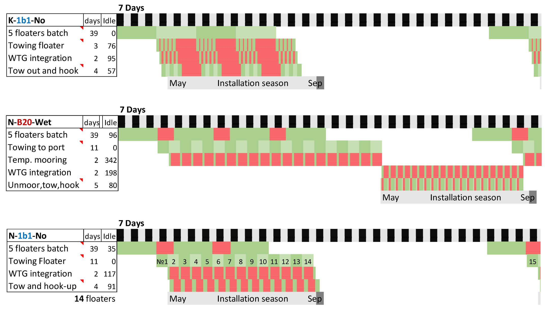
  • One-by-one (1b1): Install the turbine as soon as a floater is ready and then pay for the crane’s idle time before the next installation.
  • Batches of 20 (B20): Wait for a batch of 20 floaters to be ready for integration in one season to minimise the crane idle time.
A crane would be rented each season. In such cases, floaters must be wet-stored (temporarily moored in the harbour) or dry-stored on the quay (only for on-quay assembly, as moving floaters up and down the quay is complicated). No floater storage is required for one-by-one integration. Marine operation time is based on completed projects around the world, compiled by T. Hasumi [34].
After a cost evaluation under several assumptions, Strategy No. 1 gives the lowest overall cost. Its low cost mainly comes from the lowest turbine integration cost due to its high crane time efficiency, as the components are located conveniently on-site.
Table 6. Seven FOWT integration strategies.
Strategies No.1
Q-B20-Dry
2
Q-B20-Wet
3
Q-1b1-No
4
K-B20-Wet
5
K-1b1-N
6
N-B20-Wet
7
N-1b1-No
Floater ConstructionOn-quayOn-quayOn-quayKaohsiungKaohsiungNagasakiNagasaki
Turbine IntegrationBatches of 20Batches of 20One-by-oneBatches of 20One-by-oneBatches of 20One-by-one
StorageDryWet(n/a)Wet(n/a)Wet(n/a)
Twenty floaters per batch are chosen, as twenty-five floaters cannot be installed within the time of the operational season, and in drydock, floaters are manufactured in batches of five (assuming full dry dock utilisation). Ships are assumed to be contracted for a minimum of several months of the continuous contract. Thus, the time between installations/tows is paid idle time. Ten assembly teams are working in two 8-h shifts without holidays in all cases.In all cases, 20 floaters can be installed during one installation season, but in the N-1b1-No case, only 14 can due to the long towing time from Nagasaki to Taichung, as seen in Figure 7. To compare the total time and cost, quay space rent must be estimated first.
Quay requirements vary depending on the dry or wet storage method; both are shown in Figure 8. In both cases, more plots are available than the current Taiwan Port authority’s arrangement that divides the quay into two plots. However, there is only enough space for wet storage of one project’s floaters, so only one of the plots could be utilised for a floating wind project with wet storage. Possible division configurations are shown in Table 7; all seven developers participating in the floating wind auction could be allocated a quay plot, or all three winners could be allocated a dry storage plot. Assembly zone dimensions are based on the existing Smulders’ facility in France, where SBM’s TLP and semi-sub WindFloat floaters were assembled successfully [35].
With the storage space requirements calculated, the quay rent price can be estimated using the price known from industry experience—0.03 USD/m2/day. Dry dock space is valued at 1 USD/m2/day. The AHT and tug charter prices from [36] were doubled to account for the installation crew and equipment; three small tugs are used for towing and temporary mooring, while an AHT is used for tow-out and hook-up. All the assumed costs are shown in Table 8.
It is further assumed that the farm developer rents quay/drydock and employs their own welders and other personnel to perform the assembly works. This assumption is required to eliminate commercial considerations from drydock vs on-quay assembly and compare them fairly. In reality, there will be both a revenue margin paid to the shipyard but also savings due to the shipyard’s experience and scale, which could not be determined in the scope of this research. It is further assumed that, in both quay and dock assembly, individual parts such as columns are sourced at nearby enterprises (1-day sailing distance), delivered by the semi-submersible vessel and then unloaded by SPMTs.
Table 9 compares the time and cost of the seven assembly strategies. Except for case N-1b1-No, which is limited by the towing time from Nagasaki to Taichung, it takes a relatively similar time to install 100 floaters. The results are also visualised in Figure 9. However, comparison by cost provides the following remarks:
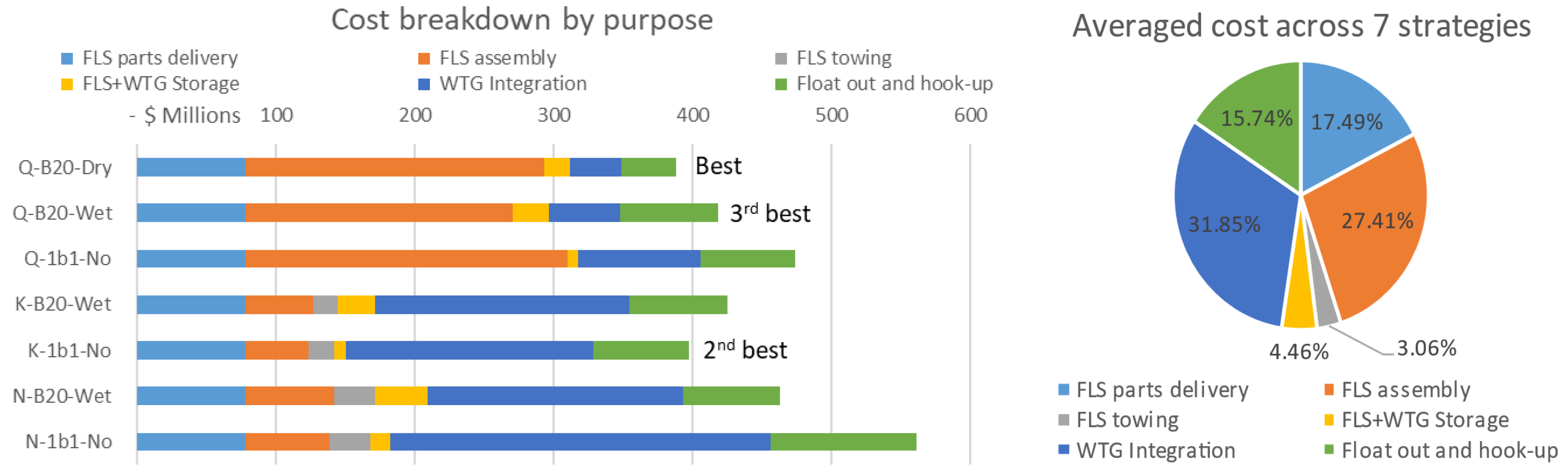
  • Strategy No. 1, Q-B20-Dry (Taichung quay, batch 20 and dry storage), gives the lowest overall cost. Its low cost mainly comes from the lowest turbine integration cost due to its high crane time efficiency, as the components are located conveniently on-site.
  • Dry dock and towing costs balance out crane costs. Thus, dry dock assembly has a similar cost as an on-quay assembly. The duration is also similar. If a cheaper crane solution can be found (buy second-hand, share, etc.), on-quay assembly can be made significantly cheaper.
  • On-quay assembly and immediate turbine integration are as good as on-quay assembly and dry storage, giving choice flexibility based on other factors.
  • When it comes to wet storage, it is cost-ineffective if paired with on-quay assembly or if the drydock is close by (Kaohsiung). However, it can be slightly beneficial if the drydock is far (Nagasaki). Combined with a limited wet storage area in the harbour, wet storage is the worst choice overall.
  • Comparing batch vs one-by-one turbine integration, waiting for a batch helps save costs due to the reduced crane hire time, but just-in-time turbine integration generally allows the fastest project execution overall.
Table 9. Assembly strategies rated by time (top) and equipment cost (bottom); red bars graphically represent the total cost.
Floaters Installed
WeldingCraneTugsAHTSemi-subSMPTQuayDock40 pcs100 pcs
DaysDaysDaysDaysDaysDaysDaysDaysDaysDays
Q-B20-Dry700390-4003901,0901,624-6161,624
Q-B20-Wet7003906757006657001,624-6161,624
Q-1b1-No700675-6856707001,491-4831,491
K-B20-Wet9756951,315700--1,7737806781,773
K-1b1-No780675680685--1,6417805461,641
N-B20-Wet1,2956952,155700--1,9051,0207621,905
N-1b1-No1,0641,0361,1001,050--2,7541,0309292,754
WeldersCraneTugsAHTSemi-subSMPTQuayDry dockTotal
$ mil.$ mil.$ mil.$ mil.$ mil.$ mil.$ mil.$ mil.$ mil.
Q-B20-Dry10.75103.07-40.00106.58109.2118.58-388Wind 04 00019 i001
Q-B20-Wet10.75103.0718.2370.00134.0873.898.26-418
Q-1b1-No10.75178.40-68.50134.5873.897.58-474
K-B20-Wet14.98183.6835.5170.0067.5810.499.0233.38425
K-1b1-No11.98178.4018.3668.5067.5810.498.3433.38397
N-B20-Wet19.89183.6858.1970.0067.5810.499.6943.66463
N-1b1-No16.35273.7329.70105.0067.5810.4914.0044.08561
In the UK, a project in the Celtic Sea with a methodology similar to case N-1b1-No was investigated [3]. The floater was towed for 4.5 days (accounting for weather) through 517 nautical miles from a construction site in Ferrol, Spain, to the integration port Milford Haven, UK. In the N-1b1-No case, the floater was towed 9 days through 827 nautical miles (without accounting for weather). Nevertheless, towing 100 floaters were installed in 2754 days in N-1b1-No, very similar to 2700 days (on average) in the Celtic Sea project, confirming the two studies’ methodology is credible and relatable.
Figure 9. Assembly cost breakdown charts, with Q-B20-Dry being the best overall.
Wind 04 00019 g009

6. Discussion

Apart from the cost factors, other factors influence strategy choice, including carbon emissions, industrial localisation policies, supply chain risk, supply capacity and workforce availability. These are briefly reviewed here, but further research by relevant disciplines is needed.
Emissions reduction is a major goal for the wind industry. Even as the power generated by the turbines is clean, a multitude of equipment is used during the installation phase and beyond, including transportation and installation vessels running on heavy fuel oil [37]. In this study, on-quay manufacturing results in an average 35% reduction in vessel time (thus emissions) compared to manufacturing elsewhere.
Localisation of the supply chain is a goal for many countries [38]. No matter where the parts come from, on-quay or local drydock manufacturing provides at least 80 welder and crane operator jobs and many further supporting personnel jobs. Local businesses such as turbine components, steel, lifting equipment, vessels and other manufacturers can further benefit if parts are procured locally [39].
At the same time, Taiwan’s supply chain for these components is limited [40] and has a history of underperformance despite government incentives [26]. This introduces a significant supply risk. It is higher in the case of wet storge, as vessel procurement is another issue [2]. Foreign manufacturing is also a risk, as facilities worldwide are limited [39,41], and countries will probably try to fill their demand before exporting. The supply risk can be identified as a problem for all FOWT assembly strategies [41].
Workforce availability is a major concern for developing and developed countries alike. Developed countries lack critical personnel such as qualified welders and crane operators. This gap is partially filled by the immigration of such workers from developing countries, leaving their original country also short of supply [42]. The Taiwanese government has classified welders and shipbuilding welders in particular as a job with a critical cadre shortage [26,27]. This imposes a high risk on local manufacturing.
From these considerations, on-quay manufacturing is a good, well-rounded strategy if enough skilled workers can be hired and brought on for long-term work in the harbour.

7. Conclusions and Recommendations

This paper analysed different strategies for assembling and integrating floating offshore wind turbines at a port. The context is for a hypothetical 100-floater farm based on the TaidaFloat semi-submersible floater. As TaidaFloat is designed to operate on the Taiwan Strait, Taichung and other nearby ports were reviewed for the study. Several strategies regarding floater construction/assembly and turbine integration were researched and compared. The following conclusions may be made:
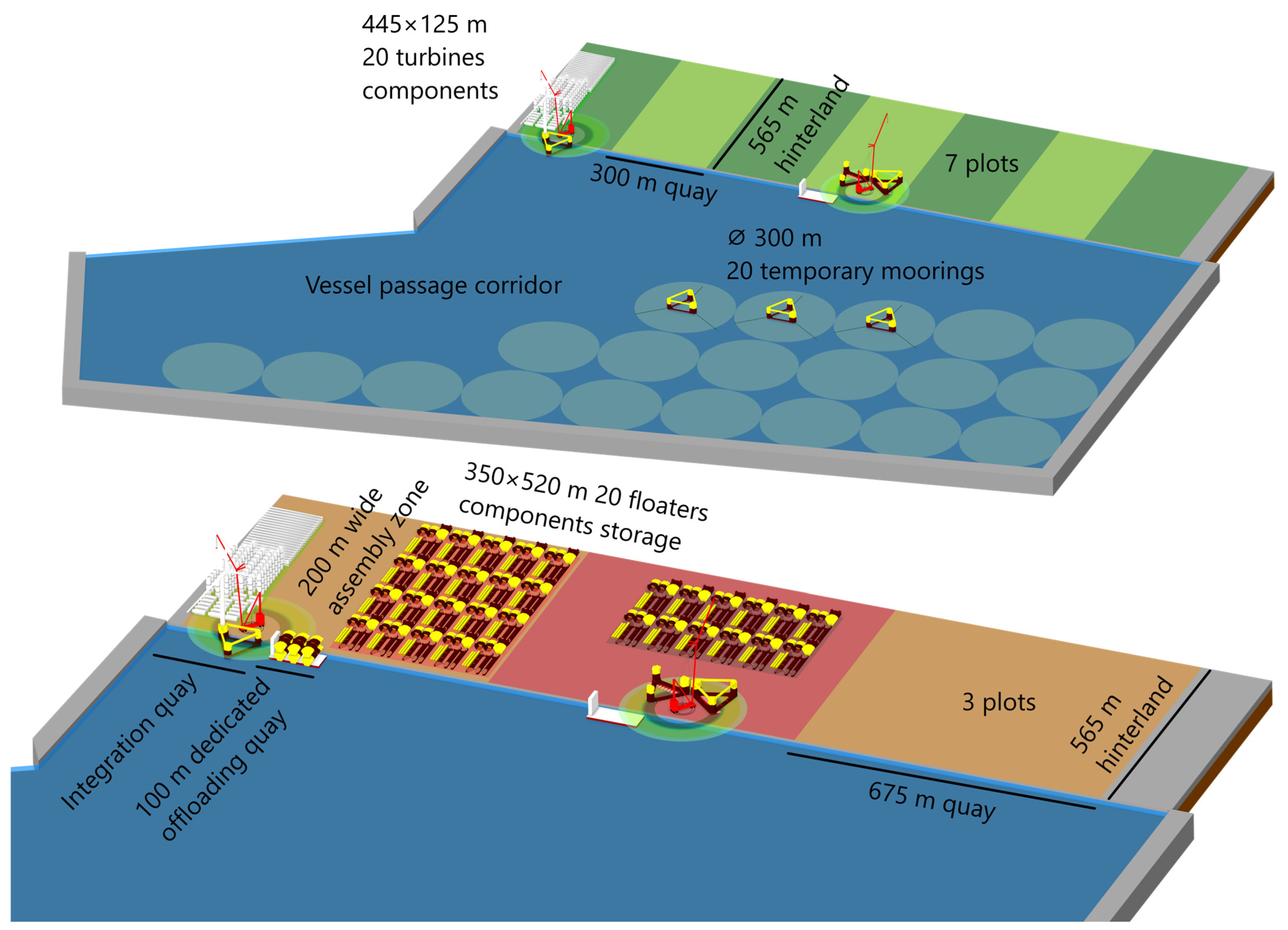
  • Floater on-quay assembly in Taichung Port may be the most cost-effective compared to remote drydock assembly. After a cost evaluation under several assumptions, the integration strategy (Q-B20-Dry) using Taichung quay, a batch of 20 floaters and dry storage gives the lowest overall cost. Its low cost mainly comes from the lowest turbine integration cost due to its high crane time efficiency, as the components are located conveniently on-site.
  • A complete list of possible port operations with necessary equipment is summarized for a FOWT project. Regarding selecting a floater launching method, the most viable method may be using a semi-submersible barge (e.g., a floating dock). This is based on the assumption that the hull assembly work will be carried out at Taichung Port in an ideal situation. This launching method avoids the long-distance wet tow from a shipyard with a drydock to the port.
  • A very large crane (e.g., a ring crane) is needed even for floater designs with a turbine on the side column. A large crane may be enough to install the turbine in both central and side columns, making the argument that a side-column turbine may not gain too much advantage. However, the side-column location could show its advantage if the large crane is impossible to procure due to short supply. In that situation, a tandem of two smaller crawler cranes could install the turbine.
The complex work of floater assembly and turbine integration was investigated in this research. It is aimed to guide wind energy developers, port authorities, project contractors and government agencies. Some of the findings and conclusions may be useful under the stated background and assumptions. The research findings may help in decision-making for the future development of wind energy.

Author Contributions

Conceptualization, G.I.; methodology, G.I.; Validation, K.-T.M.; formal analysis, G.I.; investigation, G.I.; writing—original draft preparation, G.I.; writing—review and editing, K.-T.M.; visualization, G.I.; supervision, K.-T.M.; funding acquisition, K.-T.M. All authors have read and agreed to the published version of the manuscript.

Funding

This research was funded by National Science & Technology Council, grant number 111-3116-F-002-007 and Ministry of Education’s Yushan Fellow Programme, grant number 112V1005-3.

Institutional Review Board Statement

Not applicable.

Informed Consent Statement

Not applicable.

Data Availability Statement

Data is contained within the article.

Acknowledgments

The authors highly appreciate the funding support from the two government agencies of Taiwan.

Conflicts of Interest

The authors declare no conflicts of interest.

References

  1. Stehly, T.; Beiter, P.; Duffy, P. 2019 Cost of Wind Energy Review; National Renewable Energy Lab (NREL): Golden, CO, USA, 2020. Available online: https://www.nrel.gov/docs/fy21osti/78471.pdf (accessed on 28 August 2024).
  2. Hong, S.; McMorland, J.; Zhang, H.; Collu, M.; Halse, K.H. Floating offshore wind farm installation, challenges and opportunities: A comprehensive survey. Ocean Eng. 2024, 304, 117793. [Google Scholar] [CrossRef]
  3. Torres, E.S.; Thies, P.R.; Lawless, M. Offshore Logistics: Scenario Planning and Installation Modeling of Floating Offshore Wind Projects. ASME Open J. Eng. 2023, 2, 021013. [Google Scholar] [CrossRef]
  4. Díaz, H.; Guedes Soares, C. Approach for Installation and Logistics of a Floating Offshore Wind Farm. J. Mar. Sci. Eng. 2023, 11, 53. [Google Scholar] [CrossRef]
  5. BVG Associates. Guide to a Floating Offshore Wind Farm; Offshore Renewable Energy Catapult: Blyth, UK, 2023. [Google Scholar]
  6. Zhou, S.; Müller, K.; Li, C.; Xiao, Y.; Cheng, P.W. Global sensitivity study on the semisubmersible substructure of a floating wind turbine: Manufacturing cost, structural properties and hydrodynamics. Ocean Eng. 2021, 221, 108585. [Google Scholar] [CrossRef]
  7. Ferri, G.; Marino, E. Site-specific optimizations of a 10 MW floating offshore wind turbine for the Mediterranean Sea. Renew. Energy 2023, 202, 921–941. [Google Scholar] [CrossRef]
  8. Hsu, I.-J.; Ivanov, G.; Ma, K.-T.; Huang, Z.-Z.; Wu, H.-T.; Huang, Y.-T.; Chou, M. Optimization of Semi-Submersible Hull Design for Floating Offshore Wind Turbines. In Proceedings of the 41st International Conference on Offshore Mechanics and Arctic Engineering (OMAE 2022), Hamburg, Germany, 5–11 June 2022. [Google Scholar]
  9. Ivanov, G.; Hsu, I.-J.; Ma, K.-T. Design Considerations on Semi-Submersible Columns, Bracings and Pontoons for Floating Wind. J. Mar. Sci. Eng. 2023, 11, 1663. [Google Scholar] [CrossRef]
  10. Lai, Z.-Y.; Ivanov, G.; Chen, J.-C.; Chen, D.; Ma, K.-T. Mooring Anchor radius and Spread-angle Optimization for a 2 MW Semi-Submersible Floating Wind Turbine in Taiwan Strait. In Proceedings of the International Conference on Ocean, Offshore and Arctic Engineering (OMAE 2024), Singapore, 9–14 June 2024. [Google Scholar]
  11. Chen, C.-A.; Chen, K.-H.; Igarashi, Y.; Chen, D.; Ma, K.-T.; Lai, Z.-Y. Design Of Mooring System for a 15mw Semi-Submersible, Taidafloat, in Taiwan Strait. In Proceedings of the 42nd International Conference on Ocean, Offshore and Arctic Engineering, Melbourne, Australia, 11–16 June 2023. [Google Scholar]
  12. Wu, K.-Y.; Ivanov, G.; Hsu, I.-J.; Ma, K.-t.; Chiang, M.-H. Technology Development of a Floating Offshore Wind Turbine, “TaidaFloat”. In Proceedings of the Taiwan Wind Energy Conference 2023, Taipei, Taiwan, 18–20 October 2023. [Google Scholar]
  13. Gaertner, E.; Rinker, J.; Sethuraman, L.; Zahle, F.; Anderson, B.; Barter, G.E.; Abbas, N.J.; Meng, F.; Bortolotti, P.; Skrzypinski, W. IEA Wind TCP Task 37: Definition of the IEA 15-Megawatt Offshore Reference Wind Turbine; National Renewable Energy Lab (NREL): Golden, CO, USA, 2020. [Google Scholar]
  14. Jensen, M.B.; Kofoed-Hansen, H.; Hansen, A.; Christensen, L.M.; Hess, M.; Jørgensen, A.; Hsu, M. Offshore Wind Port Feasibility Study of Taichung Harbor, Taiwan. 2016. Available online: https://www.academia.edu/33881798/Offshore_Wind_Port_Feasibility_Study_of_Taichung_Harbor_Taiwan_Taichung (accessed on 9 August 2024).
  15. Taiwan International Ports Corporation. Port Layouts. 2024. Available online: https://www.twport.com.tw/en/cp.aspx (accessed on 9 August 2024).
  16. Terex. Terex CC9800 Crawler Crane Specification. 2009. Available online: https://storage.bigge.com/webstorage/crane-charts/Demag-CC9800.pdf (accessed on 28 August 2024).
  17. Liebherr. Technical Data—LR 13000. 2024. Available online: https://www.liebherr.com/en/int/products/mobile-and-crawler-cranes/crawler-cranes/lr-crawler-cranes/lr-13000.html (accessed on 28 August 2024).
  18. Liebherr. Game Changer for Tomorrow's Energy. LR12500-1.0 Crawler Crane. 2023. Available online: https://www.liebherr.com/external/products/products-assets/68260ca3-3e8d-4366-9019-5413e68d6bf1-10/liebherr-281-lr-12500-1.0-281-00-defisr10-2023.pdf (accessed on 28 August 2024).
  19. Mammoet. Mammoet-Giant JV Supports Manufacturing of Taiwan’s First Wind Turbine Jacket Foundations. Available online: https://www.mammoet.com/news/mammoet-giant-jv-supports-manufacturing-of-taiwans-first-wind-turbine-jacket-foundations/ (accessed on 23 May 2024).
  20. Mammoet. MAMMOET PTC 200-DS Dimensions. 2015. Available online: https://www.mammoet.com/equipment/cranes/ring-cranes/ptc-200-ds/ (accessed on 28 August 2024).
  21. Mammoet. SPMT Scheuerle Dimensions and Specifications. 2015. Available online: https://www.mammoet.com/siteassets/06-equipment/transport/self-propelled-modular-transporter/datasheet-SPMT-Scheuerle/ (accessed on 28 August 2024).
  22. Tayyar, G.T. Welding in Shipbuilding; Martin Leduc. 2008. Available online: https://www.dieselduck.info/machine/04%20auxiliary/2008%20Ship%20Welding.pdf (accessed on 28 August 2024).
  23. Scheid, P. Sailing Cargo Ship|Shipyard Vietnam—Hull Block Heavy Lift & installation|Dop Peter Scheid. YouTube. 2023. Available online: https://www.youtube.com/watch?v=speTKU4Bkcg (accessed on 28 August 2024).
  24. Ocergy. About OCG-Wind. Available online: https://www.ocergy.com/ocg-wind (accessed on 23 May 2024).
  25. Stiesdal. Tetra Offshore Foundations for Any Water Depth. Available online: https://www.stiesdal.com/offshore/tetra-offshore-foundations-for-any-water-depth/ (accessed on 23 May 2024).
  26. Ivanov, G. Ukraine—Taiwan Offshore Wind Joint Venture. Promising Cooperation for Achieving Energy Independence. Int. J. Bus. 2024, 29. [Google Scholar] [CrossRef]
  27. National Development Council (Taiwan). 2021–2023 Annual Survey and Estimation of Talent Supply and Demand in Key Industries; Taiwan. 2021. Available online: https://ws.ndc.gov.tw/Download.ashx?u=LzAwMS9hZG1pbmlzdHJhdG9yLzE4L3JlbGZpbGUvNjAzNy85NTEwLzkxN2I0ZDk4LTRkNzAtNDk0OC1hNDM3LTVhMmI4MGVkNDQ0Ni5wZGY%3D&n=MTEwLTExMuW5tOmHjem7nueUoualreS6uuaJjeS%2Bm%2BmcgOiqv%2BafpeWPiuaOqOS8sCgxMDnlubTovqbnkIbmiJDmnpzlvZnmlbTloLHlkYopLnBkZg%3D%3D&icon=..pdf (accessed on 28 August 2024).
  28. van der Kaaij, I. Evaluating the workability of On-Site Assembly of a 15MW Wind Turbine Blade on a Semi-Submersible Floating Wind Turbine Using a Crane Vessel. Master’s Thesis, Norwegian University of Science and Technology, Trondheim, Norway, 2023. [Google Scholar]
  29. Vestas. Building the V236-15.0 MW™ Offshore Turbine Prototype|Episode 3: The Installation. YouTube. 2023. Available online: https://www.youtube.com/watch?v=xRqwEnb8K68 (accessed on 28 August 2024).
  30. Bigge. Operated & Maintained Crane Rental Rates. Available online: https://www.bigge.com/crane-rental/operated-and-maintained/ (accessed on 23 May 2024).
  31. Ralls, M.L.; Newman, R. Introduction on Use of Self Propelled Modular Transporters (SPMTs) to Move Bridges; National Highway Institute: Vienna, VA, USA, 2008. [Google Scholar]
  32. Shandong Panda Mechanical Co. For Sale: 150 ton 10 Axle 12 Axle Line Spmt Self Propelled Modular Transporter Trailer. 2024. Available online: https://www.alibaba.com/product-detail/150-ton-10-axle-12-axle_1600987143384.html?spm=a2700.7724857.0.0.44cd4d58LXp6Ei (accessed on 4 June 2024).
  33. Crowle, A.; Thies, P. Floating offshore wind turbines port requirements for construction. Proc. Inst. Mech. Eng. Part M: J. Eng. Marit. Environ. 2022, 236, 1047–1056. [Google Scholar] [CrossRef]
  34. Hasumi, T.; Yokoi, T.; Haneda, K.; Chujo, T.; Fujiwara, T. Estimation For Efficiency of Offshore Installation Process of Floating Offshore Wind Turbines in Japan. In Proceedings of the 42nd International Conference on Ocean, Offshore and Arctic Engineering, Melbourne, Australia, 11–16 June 2023. [Google Scholar]
  35. Buljan, A. Floaters for French Pilot Wind Farm Taking Shape. offshoreWind.biz. 2022. Available online: https://www.offshorewind.biz/2022/07/14/floaters-for-french-pilot-wind-farm-taking-shape/ (accessed on 28 August 2024).
  36. Chitteth Ramachandran, R.; Desmond, C.; Judge, F.; Serraris, J.J.; Murphy, J. Floating wind turbines: Marine operations challenges and opportunities. Wind Energ. Sci. 2022, 7, 903–924. [Google Scholar] [CrossRef]
  37. Arvesen, A.; Birkeland, C.; Hertwich, E.G. The Importance of Ships and Spare Parts in LCAs of Offshore Wind Power. Environ. Sci. Technol. 2013, 47, 2948–2956. [Google Scholar] [CrossRef] [PubMed]
  38. Ferry, T. Offshore Wind Industry Struggles with Localisation. In Euroview; European Chamber of Commerce Taiwan: Taipei City, Taiwan, 2022; Available online: https://euroview.ecct.com.tw/category-inside.php?id=412 (accessed on 28 August 2024).
  39. Uttley, E.; Martin-Venner, K.; Scott, M.; Williams, S.B. Port and Manufacturing Infrastructure Investment Models. In Offshore Renewable Energy Catapult; Floating Offshore Wind Centre of Excellence: Aberdeen, Scotland, 2024; Available online: https://fowcoe.co.uk/wp-content/uploads/2024/03/FOW-CoE-PR50-Port-Infrastructure-and-Manufacturing-Investment-Models.pdf (accessed on 28 August 2024).
  40. Metal Industry Intelligence. The Supply Chain Study of Offshore Wind Industry in Taiwan. 2022. Available online: https://www.bcctaipei.com/sites/default/files/2022-03/Taiwan%20Offshore%20Wind%20Supply%20Chain%20Report%200322.pdf (accessed on 28 August 2024).
  41. Smith, B.M.; Ongley, J.; Angeloudis, A.; Thies, P.R. Mitigation of assembly constraints for floating offshore wind turbines using discrete event simulation. J. Phys. Conf. Ser. 2023, 2626, 012044. [Google Scholar] [CrossRef]
  42. Pronoza, P. Ukraine shipbuilding and world: Features and trends. Econ. Manag. Law: Probl. Prospect. 2015, 215, 102. [Google Scholar]
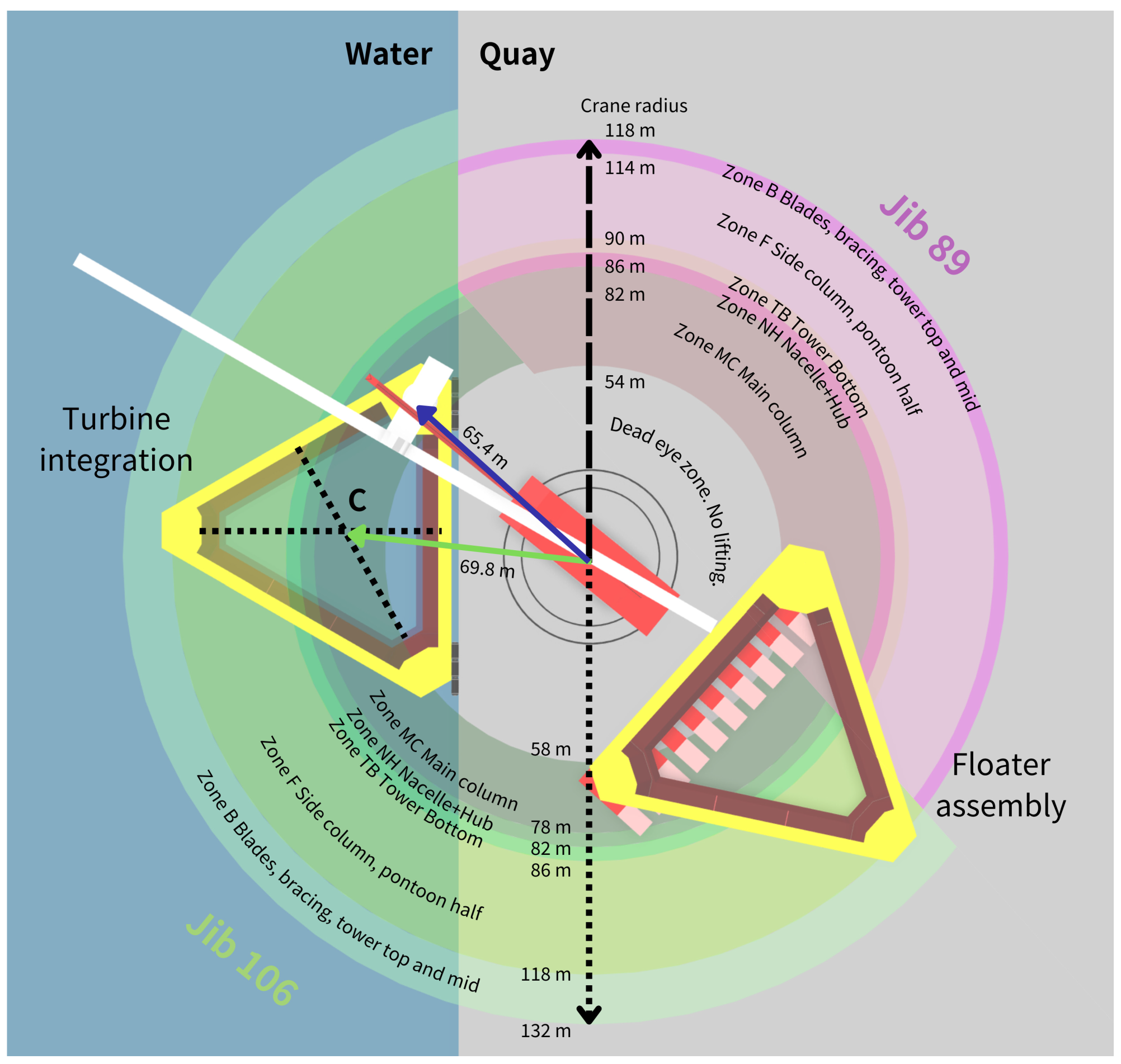
Figure 1. Future arrangements for accommodating the integration and assembly of floating wind turbines, using Taichung Port as an example. Reworked based on a picture from [15].
Wind 04 00019 g001
Figure 2. Crane definitions. Photo courtesy of CraneHotLine, Liebherr and Mammoet.
Wind 04 00019 g002
Figure 3. Working zone of a ring crane shown together with 15 MW TaidaFloat for 2 jibs.
Wind 04 00019 g003
Figure 4. Ways to launch a floater. Pictures courtesy of Principle Power, Ocergy and Bardex.
Wind 04 00019 g004
Figure 5. Floater quayside block assembly, steps 1 to 4.
Wind 04 00019 g005
Figure 6. Crane price extrapolation.
Wind 04 00019 g006
Figure 7. FOWT assembly Gantt charts of the 7 strategies. Red denotes rental equipment idle time, and green and light green – the sequence of activities. To scale, capped at 415 days.
Wind 04 00019 g007aWind 04 00019 g007b
Figure 8. Possible wet (top) and dry (bottom) floater storage arrangements in Taichung Port.
Wind 04 00019 g008
Table 2. Summary of the components that need to be lifted with weights, and the maximum workable radii.
Using PTC 200-DS 140 Crane Crane Radius, m
15 MW IEA TurbineQuantityMass, tJib 106Jib 101Jib 89
Tower top1213132132118
Tower mid1252132132118
Tower bot1796868690
Nacelle+Hub1822828686
Blade 1x365208200118
Total 2280
TaidaFloat(ver. 4.1.6A)
Main Column1883788282
Side Column2492122118114
Pontoon half6521118118114
Brace3152132132118
Total 5448
Table 3. Floater assembly procedure and estimated time.
No.Assembly ProcedureThickness, mmSeam Length, mTime, h
1Pontoon 1 lift30 5.0
2Pontoon 1 middle weld3050.6189.2
3Pontoon 1 butt weld 13087.7327.8
4Pontoon 1 butt weld 23087.7327.8
5Pontoon 2 lift30 5.0
6Pontoon 2 middle weld3050.6189.2
7Pontoon 2 butt weld 13087.7327.8
8Pontoon 2 butt weld 23087.7327.8
9Pontoon 3 lift30 5.0
10Pontoon 3 middle weld3050.6189.2
11Pontoon 3 butt weld 13087.7327.8
12Pontoon 3 butt weld 23087.7327.8
13MC lift 130 5.0
14MC bottom weld30170634.0
15MC lift 230 5.0
16MC mid weld30142529.2
17SC 1 lift30 5.0
18SC 1 weld30124462.1
19SC 2 lift30 5.0
20SC 2 weld30124462.1
21Bracing 1 lift20 53.0
22Bracing 1 weld 1203052.2
23Bracing 1 weld 2203052.2
24Bracing 2 lift20 53.0
25Bracing 2 weld 1203052.2
26Bracing 2 weld 2203052.2
27Bracing 3 lift20 53.0
28Bracing 3 weld 1203052.2
29Bracing 3 weld 2203052.2
30Internal systems outfitting 72.0
31Transportation to barge 24.0
32Towing to quay 12.0
Total Manhours5237
Table 4. Estimated welding time by thickness [22].
Electro Gas Manual Welding
Thickness, mm101520253035
Hours to weld 5 m6.87.68.710.313.118.7
Hours to weld 1 m1.361.521.742.062.623.74
Weld area preparation, h222222
Table 5. Taichung Port wind statistics. Workable months and days are highlighted in green. Adapted from [14].
MonthMean Speed (m/s)Max. Wind Speed/DirectionWind Speed < 5 m/s (%)Wind Speed 5–10 m/s (%)Wind Speed 10–15 m/s (%)Wind Speed > 15 m/s (%)Direction N-E (%)Direction E-S (%)Direction S-W (%)Direction W-N (%)Wind Speed < 10 m/sDaysWorkable Days
Jan13.828.4/NE7.319.524.948.390.92.31.15.727%318
Feb11.727.8/N18.822.124.13582.83.86.17.141%2912
Mar10.532.4/NE25.223.923.527.576510.6849%3115
Apr7.930.1/NNE32.637.818.411.358.97.822.510.670%3021
May727.6/NE35.144.315.6550.5732.49.979%3125
Jun7.121.1/SW28.851.517.22.527.41054.97.680%3024
Jul6.637.5/NNE34.853.48.73.221.110.354.314.288%3127
Aug5.735.5/NNE52.63683.424.515.343.416.689%3027
Sep7.636.3/N40.431.815.812.161.49.516.611.272%3122
Oct12.440.0/NNE15.921.921.840.488.634.24.138%3011
Nov12.132.2/NNE19.919.519.940.8874.34.14.739%3112
Dec12.830.3/NNE1617.327.139.792.231.53.333%3010
Mean9.631.6/NNE27.331.618.722.463.46.8218.659%365215
Table 7. Possible quay division configurations.
Floater StorageDry + WetDry + NoWet + No
Dry storage310
Wet storage111
No storage046
Total projects467
Table 8. Daily equipment costs.
Daily Cost, USD
Crane264,293
SPMT 100 (20) lines90,566 (18,113)
3 Tugs27,000
AHT100,000
Semi-sub barge100,000
Quay 1 m20.03
Dry dock 1 m21
60 assemblers15,360
Disclaimer/Publisher’s Note: The statements, opinions and data contained in all publications are solely those of the individual author(s) and contributor(s) and not of MDPI and/or the editor(s). MDPI and/or the editor(s) disclaim responsibility for any injury to people or property resulting from any ideas, methods, instructions or products referred to in the content.

