1. Introduction
Large-scale computations for complex states of stress and complex models are now possible with the increase in computing power. In order to improve such numerical simulations, manufacturers need reliable experimental data, especially for the dynamic loadings. Reliable experimental data related to composites’ material seem to be an important issue for the industry and, indeed, for research laboratories. This study will be focused on the characterization of the nonlinear shear behavior of the T700/M21 CFRP (Carbon-Fibers-Reinforced Polymer) material. The T700/M21 exhibits a reversible shear behavior dependent on the strain rate [
1]. Concerning the nonlinear behavior, CFRP materials present both rate-dependent stress and strain at failure [
2]. The nonlinear behavior is classically characterized by the incremental cyclic test. Each cycle of loading–unloading allows for the characterization of the macroscopic damage variable, which represents the loss of rigidity until failure [
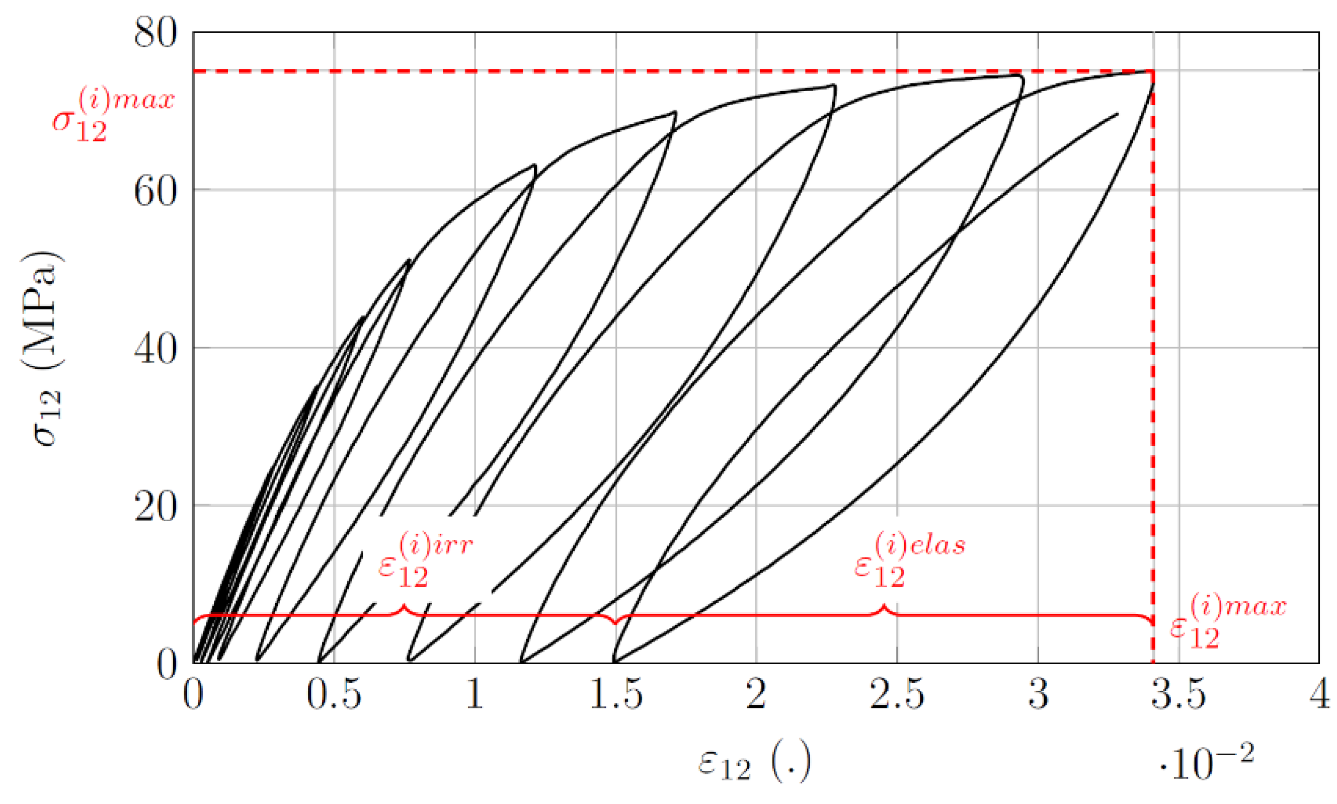
3]. The cyclic tests allow the specimens to be submitted to several levels of incremental stresses until the failure. Each loading cycle i (
Figure 1) allows for the definition of macroscopic properties for the characterization of the nonlinear behavior. The maximum strain (
) can be dissociated in irreversible (
) and elastic (
) strains by the measurement of the unloading phases for each cycle. Under dynamic loadings, these damage variables can be assessed by performing interrupted tensile tests [
4,
5].
This study will be focused on the definition of an experimental protocol for the characterization of the nonlinear behavior at intermediate strain rates adapted to T700/M21 carbon epoxy material. The latter is based on the design of an experimental interrupted tensile test device adapted to servo-hydraulic jacks.
2. Experimental Protocol
The experimental protocol proposed in this study is adapted to servo-hydraulic jacks and is based on the development of an interrupted displacement tensile test device.
Section 2.1 illustrates the working principle of servo-hydraulic jacks.
Section 2.2 presents the device designed according to the use of the servo-hydraulic jacks. The objective of the device is to perform a cyclic test, as shown in
Figure 1, under dynamic loadings.
2.1. Servo-Hydraulic Jacks Working Principle
The servo-hydraulic jacks allow for the characterization of the material behavior in tension or compression for loading rates up to
They allow for the obtention of intermediate strain rates between electromechanical machines and Hopkinson bars.
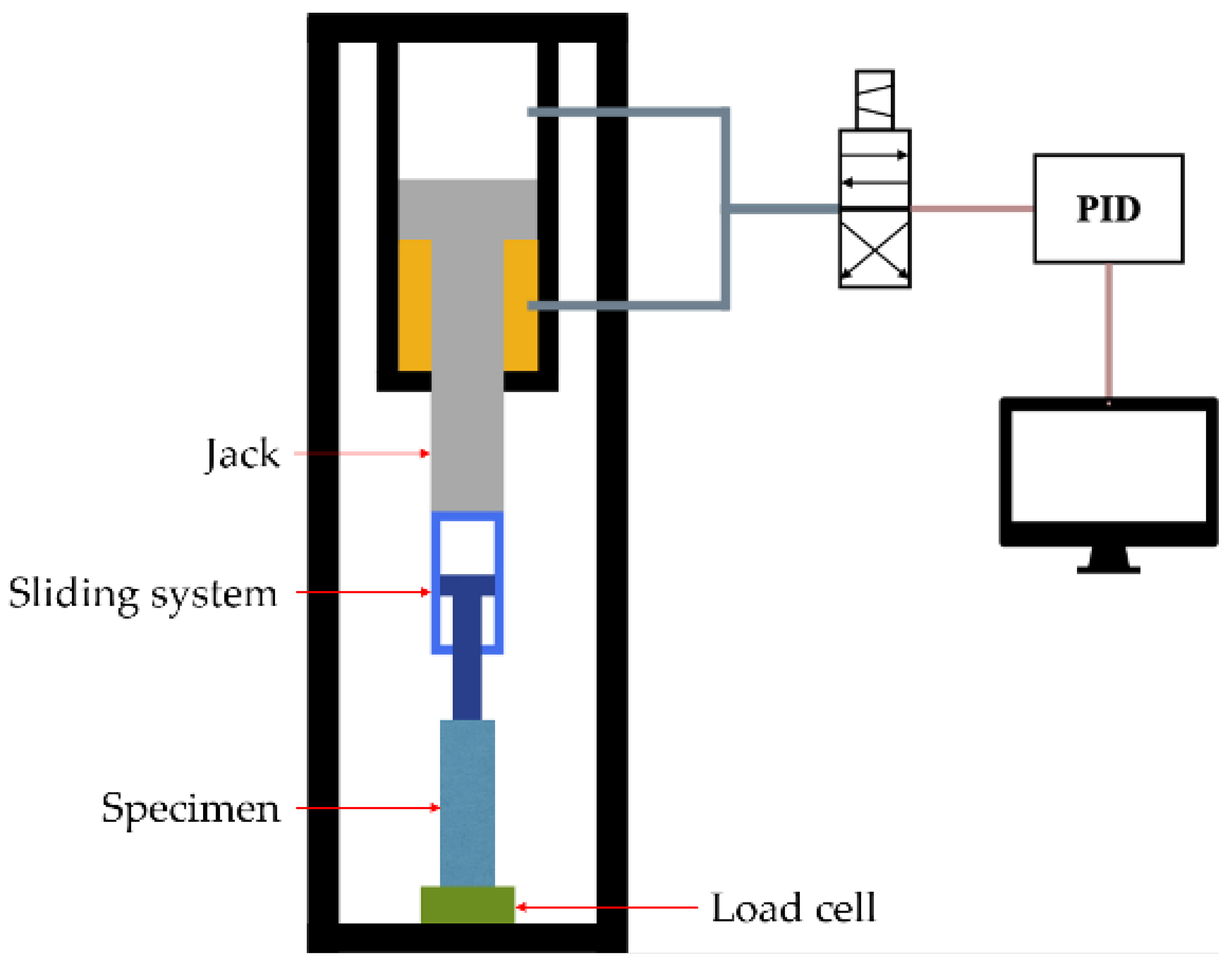
Figure 2 illustrates the use of a servo-hydraulic jack, and
Appendix A depicts the elements description of a dynamic test with this machine.
First, the specimen is placed in a series with a load cell and attached to a sliding system (
Figure 2a). Then, the expected velocity is attempted by the stroke of the sliding system (
Figure 2b). This step allows for the obtention of the defined velocity of the test before loading the specimen. Finally, the jack comes into contact with the sliding system, and the specimen starts to be under tension up to failure (
Figure 2c).
Under dynamic loadings, the PID system cannot be used to stop the loading because of the small duration of the test (≈1 ms). Therefore, the full stroke of the jack must be performed during dynamic loading. The design of the servo-hydraulic jack is a hindrance to the study of nonlinear material behavior. The device proposed in this study is a response to it.
In order to re-create the cyclic phases illustrated in
Figure 1, a dynamic test needs to be interrupted before the failure of the specimen. To the author’s knowledge, two main methods are mentioned in the literature: the interruption based on a load level [
3,
5] or based on a displacement level [
4]. In this study, the interruption method by displacement will be considered.
2.2. Interrupted Testing Protocol
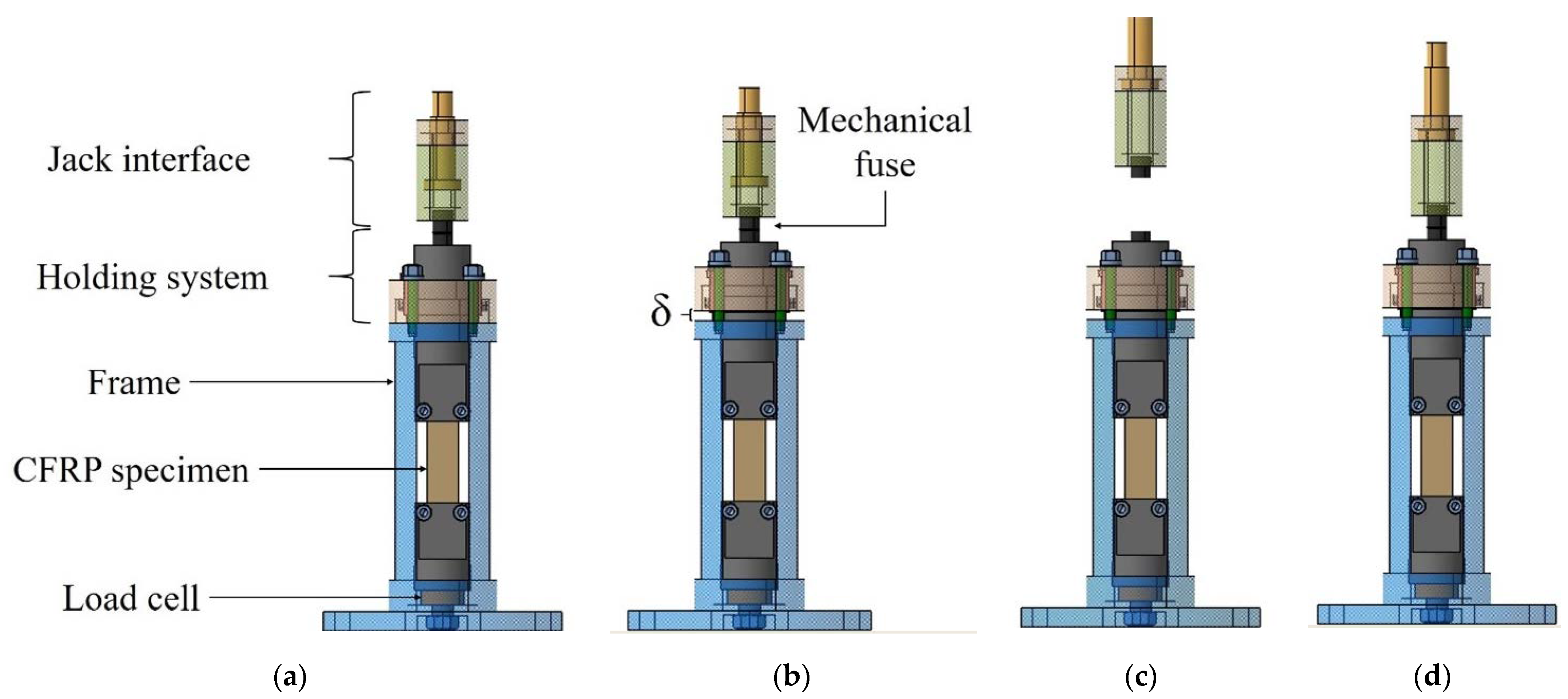
Figure 3a presents the interrupted tensile test device developed in this study.
Figure 3b–d illustrate the schematic sequence of the interrupted test protocol. The shear behavior is obtained in accordance with [
6], which defined the behavior as Equation (1) for a ± [45°]ns specimen:
where
is the shear stress (MPa), F is the applied load to the specimen (N), S is the specimen section (mm
2),
is the shear strain,
is the longitudinal strain and
is the transversal strain.
The load is measured with the piezoelectric load cell (
Figure 3), which is KISTLER© 2022A, and the strains are measured with the Vishay© CEA-06-125UNA-350 strain gauges. The protocol is adapted to an INSTRON© VHS 160/100—20 servo-hydraulic jack, which respects the working principle presented in
Section 2.1.
The holding system allows one to keep the specimen under tension after the loading. The jack interface and the mechanical fuse assure the dissociation of the jack with the device. Once the specimen is held at the delta increment (δ in mm in
Figure 3b), the loading is still applied to the specimen thanks to the holding system. After the holding, the mechanical fuse breaks to let the jack make its stroke (
Figure 3c). Finally, when re-associating the jack interface with the holding system, it is possible to unload the specimen (
Figure 3d). Each delta increment can be performed on the same specimen in order to guarantee the continuity of the nonlinear behavior characterization. The axiality of the loading is obtained by a sliding fit (H7g6) between the frame, the holding system and the jaws.
This device is also designed to allow for the possible analysis of the damage mechanisms. The four sides of the specimen are observable during the test. Observations with photography, infrared thermography and DIC (Digital Image Correlation) are therefore possible. The device can be removed from the servo-hydraulic jack without having to remove the specimen from it. Therefore, it can also be used for X-ray laminography studies with a fixed damage at a maintained strain state in the specimen.
The load cell attached to the specimen is the main advantage of this device. This allows for a guarantee of the measurement of the load throughout the tests and, thus, for the measurement of the unloading phases after the dynamic tests. To the author’s knowledge, such results are not yet present in the literature.
3. Results Obtained with the Interrupted Test Protocol
Figure 4 illustrates all the incremental cycles realized with the protocol presented in this paper for a test at
. A comparison is depicted with a Monotonous Test (MT) performed with the same experimental setup. These tests are performed with the ±[45°]ns specimen [
7] in accordance with its normalized protocol [
6]. The specimen geometry is designed in accordance with the experimental protocol for the determination of CFRP-reduced geometry adapted to dynamic loadings [
8].
The lack of data before 20 MPa observed for the δ = 0.5, 1 and 1.5 mm tests is explained by the use of the holding system. Its design requires a pre-load of the specimen. This pre-load avoids compression in the specimen after the springback effect due to fuse failure. The loss of stress at 60 MPa for δ = 2 mm and at approximately 50 MPa for δ = 2.5 mm is due to the servo-hydraulic jack working principle. During dynamic loadings, it is well known in the literature that the jack can slow down during the high strain rates tests and produce such artifacts.
As
Figure 4 illustrates, these artifacts do not influence the evaluation of the shear modulus and the maximum shear stress. As the shear modulus is computed in accordance with [
6], the shear bounds are
and are always before these artifacts. Concerning the step of δ ≤ 1.5 mm, a method for computing an equivalent modulus will be proposed and presented during the ICEM 2022 conference. With the evaluation of the shear modulus for each cycle, this protocol will allow for the computation of the damage variable, which represents the evolution of the rigidity loss. At the end of the loading phase, the specimen is held by the holding system. However, as
Figure 4 illustrates, the stresses between the end of the loading and the beginning of the unloading phases are different. This is due to the design of the holding system and will be explained by
Figure 5 in
Section 4.
The unloading phases are performed manually at a quasi-static loading rate. Through the jack interface assuring the re-association of the device to the jack, it is possible to perform the unloading phase. The increase in the shear stress-strain at the beginning of the loading phases is also due to the design of the holding system.
4. Discussions
Figure 5 highlights the two interrogations mentioned previously within
Figure 4 in
Section 3. The cyclic phase used in
Figure 5 is δ = 2.5 mm from
Figure 4, which is obtained with the device for a tensile test performed at
. The difference between the maximum stress at the end of the loading and the holding stress level before the unloading phase (∆), along with the recovery phase of the irreversible strain after the unloading phase during a zero-stress phase (∆’), are highlighted.
The mechanical slack of the holding system (0.1–0.15 mm) and its elasticity can explain the loss of the stress (Δ in
Figure 5). The holding system is realized with wire cutting Electrical Discharge Machining (EDM) and a Computer Numerical Control (CNC) machine in order to limit the amplitude of the Δ step due to the mechanical slack. Furthermore, the material used is Maragin Steel, which has high stiffness properties, in order to reduce its influence on the Δ step due to the system elasticity.
Even if the design is performed to limit the slack and the displacement due to the elastic strain of the holding system, the rigidity of the specimen tends to stress the holding system.
The protocol defined by the use of a servo-hydraulic jack and the device requires us to characterize the reversible phase (Δ’ in
Figure 5). With the use of the device for a servo-hydraulic jack, it is not possible to reload the specimen directly after the unloading phases (between phases c and d of
Figure 3). Changing the fuse requires handling and therefore time. It is necessary to take into account the analysis of reversible phases in the experimental investigation, which is not available in the literature. However, this study can provide additional information on the characterization of the nonlinear behavior of CFRP.
During dynamic loading, some viscous phenomena are activated [
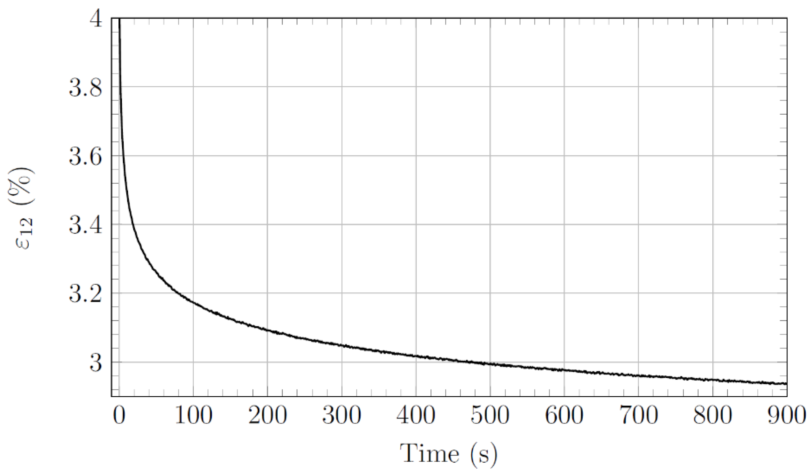
1]. In order to evaluate the irreversible strain with the same viscous state after loading, it is necessary to let these phenomena phase out. The possibility of measuring the load and the strain measurement during the all-experimental protocol helps to estimate the reversible phase after unloading. For example, in
Figure 5, this phase is non-negligible in the evaluation of the irreversible strain. Without phasing out the viscous phenomena, the irreversible shear strain is
4 % (t = 0 s in
Figure 6), and after phasing out, the specimen has ≈ 3 % of the irreversible shear strain (t = 900 s in
Figure 6). The measurement of these phases opens up possibilities such as the study of the damage effect on the viscous behavior of composite materials and therefore as a function of the strain rate.
The phase of the reversible strain as a function of the time is illustrated in
Figure 6 for the test at
and an increment of displacement of δ = 2.5 mm.
After the unloading phase, the level of the reversible strain is approximately 3%. Viscous phenomena therefore account for 1% of the total strain after a loading in the nonlinear behavior at
and delta δ = 2.5 mm. This reversible curve depicts a high nonlinear evolution as a function of time. This behavior comes mainly from the resin behavior of the composite material, which presents a high viscoelastic nonlinear behavior, observed for the thermoset [
1] and thermoplastic [
9].
Figure 7 illustrates the different reversible phases for a test at
discretized by incremental displacements of δ = 0.5 mm until failure. The shear strain is normalized by the first value of the strain at the start of the unloading phase.
The
Figure 7a illustrates that the nonlinear evolution of the reversible strain is dependent on the composite laminate’s level of damage. It is shown that the higher the loading level is, the lower the nonlinearity of the reversible phases is. As a result, it can be noticed that the reversible strain amplitude decreases with the increasing level of damage: for 0.5 mm, the capacity is 50%; for 2.5 mm, it is 30%. Apparently, the measurement of these phases can be considered as conclusive indicators of the damage of CFRPs. In addition, it seems that waiting 900 s is a consistent time for the evaluation of irreversible strains, as plateaus are observed in
Figure 7a.
Figure 7b reproduces the results in
Figure 7a, with the x-axis (time in seconds) in the logarithmic scale. As
Figure 7a shows that these reversible strain phases are nonlinear and time-dependent, it is denoted in
Figure 7b that this dependence is linear on a logarithmic scale. This result tends to show that these reversible phenomena are only related to the viscous behavior of the resin. On the other hand, it seems that these viscous phenomena are not completely ended in the logarithmic scale. The strain-time ratio is so low after 900 s that it is not conclusive enough to continue the measurement of the reversible phase after this time.
The protocol also takes into account the evaluation of the strain rate on the damage mechanisms, which are also responsible for the nonlinear behavior of composite materials.
Figure 8 depicts the specimen held under load after a displacement increment of δ = 2.5 mm at
. The picture is made possible by the holding system. The objective is to observe the damage mechanisms with the specimen under tension after a dynamic loading.
These pictures are captured on the total height of the specimen (44 mm) with a 12 MPx camera. This possibility will allow for the study of the strain rate effect on the damage pattern, which can be observed on the edges of the specimen, and also of a possible strain rate effect on the localization of damage, especially for the highest rates. This is why the picture is taken for the total height.
These results need to be further analyzed with an extensive experimental investigation regarding the repetition of the tests and the pictures. These results will be presented at the ICEM2022 conference.


 ,
, 