Abstract
This paper presents the results of residual stress distribution measured by the neutron diffraction (ND) method in an extruded 7050 aluminum alloy used to fabricate the second rib structure of an aircraft wing. Residual stresses introduced due to heat treatments still remain following stress relief steps by stretching and extrusion and are completely unknown which were predicted using finite element analysis (FEA). These complex residual stresses may significantly influence distortions during wing-rib-2 structure fabrication. ND measurements were used to validate the FEA-predicted stresses, which can be further developed to model and explore different material removal strategies to minimize and alleviate undesired distortions.
1. Introduction
The fabrication of alloyed components into their final shapes using processes such as extrusion introduces complex residual stress fields. Heat treatment is often used to improve the mechanical characteristics of the alloyed component, and this, in turn, modifies the already complex residual stress field present. Intensive research and development have previously been conducted developing numerous alloys and tempers covering all major aircraft structural parts [1]. Aircraft parts are typically manufactured monolithically from aluminum alloy, which may involve as much as 95% material removal [2]. Depending on the level of residual stress originally present in the alloyed component, the redistribution of the residual stress field caused by material removal may be path-dependent. The stress redistribution may be influenced by the cutting path and machining strategy [3]. While understanding the effect of machining parameters on the redistribution of residual stress can be quite challenging, the effect of the cutting path on stress redistribution is relatively straightforward. Moreover, it is the redistribution of the bulk residual stress field that is understood to give rise to the aircraft part distortion [4], which is the subject of the current study.
This paper presents the results of residual stress measurement using the neutron diffraction technique in an extruded 7050 aluminum alloy slab used in the manufacture of a wing rib. The measurements were particularly challenging due to the size of the component. These measurements were used to validate the present finite element prediction of the quenched residual stress distribution in the I-beam specimen following mechanical stress relief through a stretching procedure.
2. Specimen and Material Description
The 7050 aluminum alloy extrusion specimen was prismatic with an I cross-section and dimensions of 800 mm wide, 2650 mm long, and 56 mm web thickness (Figure 1a). The flange depths included 167 mm and 81 mm, with a weight of over 400 kg. This sample was used to fabricate the second rib to support the base of the wing structure of an aircraft at the wing–fuselage junction. The typical machined component shown in Figure 1b was extracted after 95% material removal from the extruded alloy.
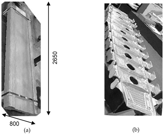
Figure 1.
Schematic of the rib-2 support structure: (a) extruded alloy, (b) machined part.
The chemical composition of aluminum alloy 7050 is provided in Table 1 [5]. In the absence of detailed material data for AA7050, the data for AA7449 were used in the present FEA study. Table 2 provides the temperature-dependent thermal properties [6], including thermal conductivity, specific heat capacity, and density for aluminum alloy 7449. Temperature-dependent mechanical properties [6], including Young’s modulus and yield stress for AA7449, are shown in Figure 2. The mechanical properties generally decrease with increasing temperatures.

Table 1.
Chemical composition of aluminum alloy 7050.

Table 2.
Temperature-dependent thermal properties for 7449 aluminum alloy.
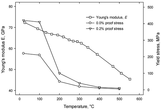
Figure 2.
Temperature-dependent Young’s modulus and yield stress for 7449 aluminum alloy.
3. Finite Element Analysis
A finite element analysis (FEA) was carried out to model the water quenching of an aluminum I-section beam sample using 7449 aluminum material data. The quench model predicted the thermal residual stress due to quenching. Further models were developed to consider stress relief through the mechanical stretching and machining of the second rib structure for subsequent part distortion study.
3.1. Finite Element Analysis of Quenching Process
The water quenching of the extruded I-beam specimen (Figure 3a) was simulated in ABAQUS 6.12 [7]. The corresponding FEA model is shown in Figure 3b. The dimensions included a longitudinal () length of 2650 mm and long transverse () of 800 mm. The width of the flange was 256 mm, and the flange thickness was 120 mm; the width of the web was 560 mm, and the web thickness was 56 mm. Due to three symmetry planes, a one-eighth FEA model was considered (Figure 3c). The quenching simulation consisted of an uncoupled heat transfer analysis with subsequent stress analysis and included structured mesh using 52,380 brick elements. The initial temperature was 470 °C. A constant heat transfer coefficient of 7000 Wm−2 K−1 [6] was assumed on the outer surface (Figure 4). No heat transfer occurred through the symmetry planes where adiabatic conditions existed. The quenchant temperature included a room temperature of 20 °C.
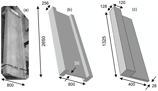
Figure 3.
Schematic of the extruded sample: (a) photograph of the sample; (b) full model of the sample; (c) one-eighth model of the sample. All dimensions in mm.
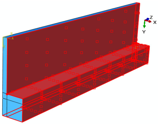
Figure 4.
One-eighth model illustrating heat transfer coefficient applied on the outer surface of the FEA model.
3.2. Finite Element Analysis of Stretching
Tensile residual stresses due to the quenching process are too large to safely work further due to the undesirable distortions that result during the fabrication of various aerospace components. Subsequently, by means of a stretching process, the residual stresses are first relieved to bring them to a safe operating level, which, in turn, helps reduce the level of distortion during component fabrication.
Several steps were involved to simulate the stress relief of the initial quenched residual stress field (Figure 5). The quenched model predicted the quenched residual stress. Due to the large longitudinal dimension of the sample, a significant dimensional change in the model occurred. After quenching simulation, the length of the extruded model shrank from 1325 mm to 1305 mm (1.5% shrinkage). The dimension of the stretch model was adjusted accordingly to account for the dimensional change. The as-quenched residual stress predicted in the quench model was mapped onto the stretch model (Figure 6) with a mesh size of 12,186 elements. Two different stretch levels, i.e., 2% and 4%, were considered in the stretch simulation. A displacement boundary condition was applied to the nodes on the free XY surface along the Z direction, illustrated by arrows. Stretching was simulated in three steps. Following mapping, the first step consisted of the equilibrium step. The load was applied in the second step: 2% stretch simulated by 26.5 mm and 4% stretch by 53 mm displacement. The model was unloaded in the third step.

Figure 5.
Flowchart illustrating the different stages in the stress relief model.
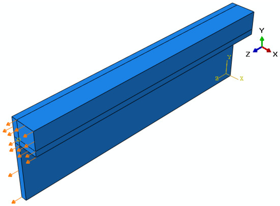
Figure 6.
One-eighth model illustrating the stretch applied along longitudinal () direction of the extruded alloy.
3.3. Finite Element Analysis of Rib Fabrication
A typical rib geometry consists of the front, second, and root ribs in an aircraft wing. Figure 7 shows the second rib structure model with the overall dimensions provided. The *model change keyword in ABAQUS was used to deactivate material sets, corresponding to the material removed during machining, thus representing the simulation of the machining process. The material removal through model change was applied in several steps to take into account the plasticity effect due to the redistribution of the complex residual stress field present in the quench–stretch model. Figure 8 provides an illustration of the final fabricated rib-2 model machined out of the extruded sample. The model also shows pockets machined out of the rib section.
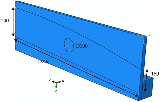
Figure 7.
Outline of the rib-2 structure to machine out of the extruded model, dimensions in millimeters.
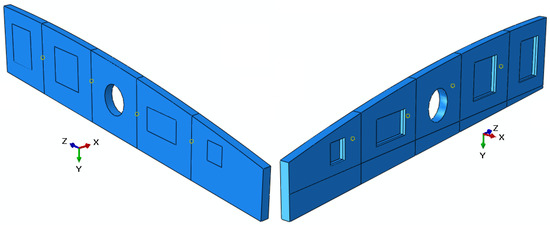
Figure 8.
Fabricated rib-2 model machined out of the extruded model.
4. Experimental Study
An experimental study including process conditions and stress measurement to characterize the residual stress of the sample and to validate the FEA simulations is provided in this section.
4.1. Process Condition
The extruded alloy was AA7050-T7651-00. The alloy was extruded and underwent solution heat treatment for a certain number of hours at 470 ± 5 °C, followed by a cold water quenching process. It was then stretched at about 2–4% to alleviate the quenching residual stresses. For metallurgy, the alloy was heat-treated for 10 h at 110 °C and then for 8 h at 175 °C.
4.2. Residual Stress Measurement
The internal residual stress field was measured using the neutron diffraction (ND) technique with an ENGIN-X stress instrument on an ENGIN-X beamline at the ISIS facility located at the Rutherford Appleton Laboratory in the UK. The method uses the time-of-flight technique [8]. Neutrons have a wave-like character and an associated wavelength, λ, of the same order of magnitude as inter-atomic spacing in solids. As such, whenever a beam of neutrons is incident on a solid, diffraction phenomena occur, which, in crystalline solids, may be used to infer information concerning the spacing between layers of atoms and, consequently, the strain. It may easily be shown that if is the angle between the incident beam and the diffracted beam, then with a polycrystalline sample, constructive interference (and a subsequent peak in intensity) occurs when Bragg’s law is satisfied
where is the interplanar spacing between planes of Miller indices (). A flux of neutrons is required to make strain measurements in crystalline materials. At ISIS facilities, neutrons are produced by accelerating protons and firing these high-energy protons onto a high atomic mass target, which causes the target nuclei to be elevated to a highly excited state, from which they immediately decay by emitting neutrons and other particles. The neutrons are collimated and focused onto the sample and used to conduct strain scans. In this spallation source, a polychromatic incident beam is directed at the specimen with a fixed scattering angle, i.e., constant , and measuring the scattered intensity as a function of wavelength . In situ, this is achieved by measuring the time-of-flight (TOF) of neutrons between the moderator and the detector, which is directly related to the wavelength through the de Broglie relationship,
where is Planck’s constant, is the mass of a neutron, is the neutron velocity, and is the distance between the moderator and the detector. A stress-free lattice spacing is required to measure the absolute values of residual elastic strain defined by diffracted and incident beam:
For a reactor source where wavelength remains the same, and . In a pulsed beam measurement instrument such as ENGIN-X, and . Residual stresses are obtained using the measured strain components through Hooke’s law.
where is Young’s modulus, and is Poisson’s ratio. Similar equations hold for and components. The internal residual stress was measured on the ENGIN-X purpose-built neutron scattering instrument for engineering residual stress measurements. Its main features include a sample-positioning device, focusing collimator slits, two position-sensitive detectors at 90° from the incident neutron beam, and a masking slit for the incident beam. The incident and diffracted beams define the sampling or gauge volume within the specimen. The diffraction data were analyzed by using the Rietveld refinement technique, which has shown to provide elastic strains analogous to the bulk equivalent strains [9].
Figure 9a illustrates the enormous size of the specimen, which required a strong support structure during ND measurement. The overall mass of the specimen was 400 kg and demanded constant supervision by safety personnel at the ISIS facility. A gauge volume was used to obtain an average over a large volume of material with a reduced neutron count time. Strain scans were made in all three principal orientations: , , and , which required the sample in both the vertical and horizontal orientations.
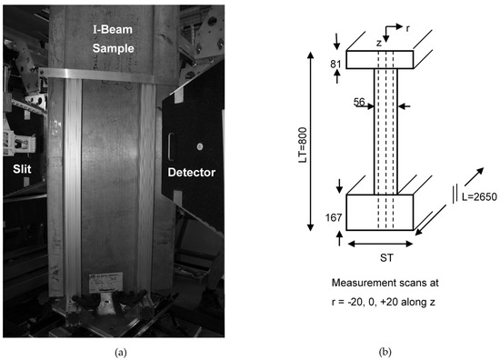
Figure 9.
Layout of the specimen for the neutron diffraction measurement: (a) sample mounted vertically in the neutron beam, (b) schematic of sample illustrating the measurement paths.
5. Results and Discussion
In the absence of a stress-free () sample, the lattice spacings measured close to the free ends (about 5 mm from the free edge) were used as the reference lattice spacing to obtain the strain components in the extruded sample. Hooke’s law was applied to calculate the three components of the stress fields: longitudinal (), short transverse (), and long transverse (). The residual stress distribution was expected to be uniform along the longitudinal direction of the extruded alloy, which was also confirmed by the FEA prediction. To optimize the allocated neutron beam time, the residual stress measurements were conducted across the span of the sample, i.e., across the direction along three paths through the thickness of the sample illustrated in Figure 9b. These measurements were sufficient to provide a well-defined overall residual stress field in the sample and to validate the FEA-predicted stress distributions. Figure 10 compares the FEA-predicted residual stress distribution with the ND-measured stresses. For clarity, the ST and LT components at r = 0 (Figure 9b) are shown. An excellent correlation was observed, validating the proposed FEA.
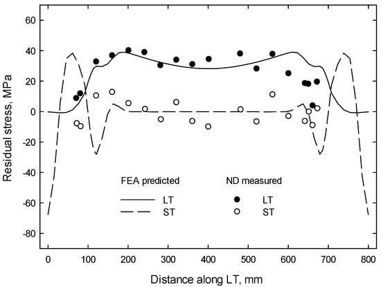
Figure 10.
Comparison of FEA-predicted residual stress distribution with the ND-measured stresses.
6. Conclusions
The measurements of residual stress fields in the extruded 7050 aluminum alloy slab using ENGIN-X at the ISIS were challenging due to its large size and weight. The measurements revealed the presence of complex residual stress distributions across the spans in the slab. Both tensile and compressive residual stress distributions existed. The residual stress measurements validated the present finite element model, which may further be developed to examine different material removal strategies to minimize distortion during the fabrication of aircraft parts. For example, a preliminary distortion result during the machining of the rib and pockets in the 2% stretch model is shown in Figure 11a. For clarity, a deformation scale factor of 50 was used. The corresponding contour plot of the LT deformation (u2) is shown in Figure 11b. Deformation in the range of −0.25 to +0.23 mm was observed. Different machining strategies may be explored using such FEA simulations with the aim of mitigating part distortions.

Figure 11.
Distortion during machining of rib and pockets in the 2% stretch model, illustrating (a) the distortion shape, and (b) its corresponding LT deformation contour plot.
Author Contributions
Conceptualization, M.S.H. and S.S.A.-H.; methodology, S.S.A.-H.; software, M.S.H. and M.S.M.; validation, M.S.H., S.S.A.-H. and M.S.M.; formal analysis, M.S.H. and M.S.M.; investigation, S.S.A.-H. and M.S.M.; resources, M.S.H.; data curation, S.S.A.-H. and M.S.M.; writing—original draft preparation, M.S.H.; writing—review and editing, M.S.M.; visualization, S.S.A.-H.; supervision, M.S.H.; project administration, M.S.H.; funding acquisition, S.S.A.-H. All authors have read and agreed to the published version of the manuscript.
Funding
This research received no external funding.
Institutional Review Board Statement
Not applicable.
Informed Consent Statement
Not applicable.
Data Availability Statement
Not applicable.
Acknowledgments
The authors are grateful to Ed Oliver (ENGIN-X), for supporting the neutron diffraction experiments, and to Military Technological College, Muscat, Oman, for other support during this study.
Conflicts of Interest
The authors declare no conflict of interest.
References
- Lequeu, P.; Lassince, P.; Warner, T.; Raynaud, G.M. Engineering for the future: Weight saving and cost reduction initiatives. Aircr. Eng. Aerosp. Technol. 2001, 73, 147–159. [Google Scholar] [CrossRef]
- Mouritz, A.P. Introduction to Aerospace Materials, Ch. 24 Disposal and Recycling of Aerospace Materials; Woodhead Publishing: Sawston, UK, 2012; pp. 558–568. ISBN 9781855739468. [Google Scholar]
- Sim, W.M. Challenges of residual stress and part distortion in the civil airframe industry. Int. J. Microstruct. Mater. Prop. 2010, 5, 446–455. [Google Scholar] [CrossRef]
- Werke, M.; Hossain, M.; Semere, D.; Wretland, A. Machining Distortion Analysis of Aerospace Components using the Contour Method. In Proceedings of the 10th Aerospace Technology Congress, Stockholm, Sweden, 8–9 October 2019. [Google Scholar] [CrossRef] [Green Version]
- The Aluminum Association. Aluminum Standards and Data; Aluminum Association Inc.: Arlington, VA, USA, 2013. [Google Scholar]
- Yu, X.; Robinson, J. Measurement of the Heat Transfer Coefficient during Quenching of the Aluminium Alloy 7449; COMPACT Project: Łódź, Poland, 2007. [Google Scholar]
- Simulia. ABAQUS Analysis User’s Manual, Version 6.12; Dassault Systemes Simulia, Inc.: Johnston, RI, USA, 2012. [Google Scholar]
- Fitzpatrick, M.E.; Lodini, A. Analysis of Residual Stress by Diffraction using Neutron and Synchrotron Radiation; Taylor and Francis: London, UK, 2003. [Google Scholar]
- Daymond, M.R.; Bourke, M.A.M.; Von Dreele, R.B. Use of Rietveld refinement to fit a hexagonal crystal structure in the presence of elastic and plastic anisotropy. J. Appl. Phys. 1999, 85, 739–747. [Google Scholar] [CrossRef]
Publisher’s Note: MDPI stays neutral with regard to jurisdictional claims in published maps and institutional affiliations. |
© 2022 by the authors. Licensee MDPI, Basel, Switzerland. This article is an open access article distributed under the terms and conditions of the Creative Commons Attribution (CC BY) license (https://creativecommons.org/licenses/by/4.0/).