1. Introduction
Power quality (PQ) is a measure of the power system performance and reliability. Among many issues related to the PQ, such as the sag, the swell, transient and, the flicker, the harmonic distortion is the primary concern [
1] and this results from the unexpectedly increasing use of the nonlinear loads such as the adjustable speed drivers, variable frequency drives and, induction furnace and especially the wide proliferation of the power electronic switching, that are all regarded the main origin of the harmonic distortion in the power systems. Nonlinear loads draw current intermittently, in a manner that does not correspond to the source sinusoidal voltage waveform. This results in the presence of voltage and current components at a frequency of an integral multiple of the fundamental frequency, often 50 Hz or 60 Hz, this effect is called the harmonic distortion [
2].
The high-level existence of the harmonic distortion in the power system might cause many problems such as controller devices malfunction, transformer overheating, power loss increase, low power factor, and communication interference [
3]. To control or get rid of the high-level harmonic distortion to a safe operation limit as approved in the IEEE 519-2014 standard [
4], the researchers have proposed over the years many techniques such as K-factor transformer [
5], tuned harmonic filter [
6], active filter [
7] and shifting transformer [
8].
The passive power filter is one of the effective tools in the industry sector due to its simple structure, lower cost, easy installation and maintenance. The passive power filter is composed of inductors and capacitors connected in series or parallel to play two roles, the first is to suppress the harmonic levels and the second is to correct the power factor, thereby enhancing the system efficiency overall [
9]. However, its drawbacks that should be considered include a series and parallel resonance with the system impedance and detuning the filter due to component parameter changes with aging [
10].
On the other hand, the active power filter can completely eliminate the harmonics and any expected resonance, in addition to achieving a unity power factor, however its very high cost compared to the passive power filter is its disadvantage.
In addition to conventional passive and active filtering approaches, advanced control strategies have recently gained significant attention for harmonic mitigation in power systems. Among these, nonlinear and robust control techniques such as composite adaptive super-twisting sliding mode control (STA-SMC) have demonstrated superior performance in handling system uncertainties and external disturbances. Despite their high performance, these advanced control strategies often involve increased implementation complexity, require precise system modeling, and depend on high switching frequencies, which may limit their practical applicability in industrial environments compared to passive filtering solutions.
The different topologies of passive filters are designed and their different combined performances are evaluated in MATLAB/Simulink, and the simulation results presented in this research shows that the proposed approach can compensate harmonic currents, reactive power, and power factor, thereby providing good dynamic and steady state performance [
11].
A single-tuned filter manages to reduce the voltage total harmonic distortion (VTHD) from 6.9% to 3.3% resulting from the 7th and 11th harmonic order generated from the capacitor bank to remedy the power factor from 73.56% to 98.27% [
12]. By the study [
1], a STPF is designed to mitigate harmonics in a 3-phase power system, specifically targeting the 5th, 7th, 11th, 13th, 17th, and 19th harmonics, effectively reducing VTHD from 15.63% to 4.87% and meeting the IEEE 519-2022 standard [
4], thereby preventing system overheating, losses, and equipment damage. They tested the performance using MATLAB/Simulink simulations. In the paper [
13], the researchers propose a novel single-tuned harmonic filter to eliminate specific harmonics in power systems without affecting the fundamental power factor, that reduces transmission loss by 0.53 times compared to conventional filters. It achieves this by using an LC branch resonating at the fundamental frequency to prevent fundamental current flow. The research in ref. [
2] focuses on the optimal reactive power selection for a STPF to avoid excessive current distortion resulting from an AC-DC converter to feed DC drive loads using the curve fitting technique. The designed filter managed to mitigate 3rd order harmonics from 38.5% to 4.1%, while VTHD of source current reduced from 40.36% to 4.51%. The authors in paper [
14] formulate the design of 3rd order damped passive power filter as a multi-objective optimization problem restrained by system’s performance indices, load power factor and, filter cost. They have solved the concerned problem using Pareto-based firefly algorithm (pb-MOFA) that provides a set of best traded-off solutions for the system. The efficiency and accuracy of the proposed algorithm are compared with Non-Dominated Sorting Genetic Algorithm (NSGA-II) and Multi-Objective Slime Mould Algorithm (MOSMA) based on three metrics, namely convergence metric (CM), generational distance (GD) and diversity metric (DM) The researchers in design a new 4th order harmonic passive filter with various design scenarios where they employed the crow spiral based search algorithm (CSSA) to solve the formulated design problem undergoing power quality constraints [
15].
The researchers discuss designing anti-resonance fourth-order passive power filters (FOPPFs) to eliminate harmonics by minimizing total demand distortion and parallel resonance index, demonstrating superior performance in resonance damping and harmonic mitigation compared to C-type filters in distorted distribution systems [
16]. The paper [
17] presents optimal placement and sizing of passive harmonic filters using multi-objective genetic algorithm tested on unbalanced IEEE 13- and 37-bus systems to mitigate harmonics, minimize filter cost and, improve voltage quality. Although the simple structure and lucid principle of the single tuned filter that composes of series LC circuit, it is a challenging task to optimally select the value of the filter components to minimize VTHD and power loss and maximize power factor. Hence, the process of ST filter design is considered a complex optimization problem, since it requires to simultaneously optimize many conflicting objective functions restrained by nonlinear power system parameters to fulfill the IEEE 519-2014 standard requirements, therefore, the use of powerful algorithm is indispensable [
13,
18].
The researchers have employed numerous meta-heuristic algorithms such as the genetic algorithms in [
9,
19], simulated annealing [
18], particle swarm algorithm, multi-objective bat algorithm in [
3] to design an optimal passive power filter to reduce the harmonic distortion and to enhance power factor with minimum power loss and reasonable cost. The paper [
20] introduces the Mixed Integer Distributed Ant Colony Optimization (MIDACO) as a new method for optimizing the sizing parameters of undamped STPFs in non-sinusoidal systems. This method is particularly effective in addressing the challenges posed by nonlinear loads and harmonics in power systems. The work in [
21] proposed an analytical method based on Monte Carlo Simulation (MCS) to investigate the harmonic performance of an optimally designed PPF with variations in power networks using the Manta Ray Foraging Optimization MRFO algorithm to effectively attenuate high-order harmonics and, reduce voltage and current distortions by approximately 54% and 30%, respectively, thereby improving system performance and compliance with standard limits. The authors in [
22] have developed PSO algorithm to get the optimal solution of planning of PPFs through combining the two objectives of harmonic reduction and cost minimization into single one function using the weight sum method.
In contrast to traditional algorithms such as Genetic Algorithm, Simulated Annealing and, Particle Swarm Optimization (PSO), Ant Colony Optimization (ACO), the firefly algorithm has been shown to outperform them in terms of convergence speed and robustness, making it suitable for real-time applications [
23]. The process of passive power filter design is considered a complex optimization problem, since the selection of the optimum value of the filter components require to optimize many conflicting objective functions restrained by nonlinear power system parameters such as the fulfillment of the IEEE 519-2014 standard requirements of VTHD besides achieving power factor greater than 90%, therefore the use of powerful algorithm is indispensable [
4,
14].
The FFA is a nature-inspired continuous optimization technique devised by Xin-She Yang in 2008, based on simulating the social behavior of tropic firefly swarm that is attracted toward other fireflies with higher flash intensity [
24]. The algorithm capitalizes on this behavior to guide the search toward an optimal solution. It is widely used for solving complex optimization problems due to its simplicity, flexibility, and ability to escape local optima by balancing exploration and exploitation in the search space [
24,
25].
The application of both single-objective and multi-objective Firefly Algorithm approaches for the performance-driven optimal design of undamped STPFs under IEEE 519-2014 constraints remains insufficiently explored. The present paper aims to apply the FFA and its extended version dealing with multi-objectives, based on the Pareto front, to optimally solve a single-tuned filter planning that achieves three objectives, the first is to reduce the VTHD to the level conforming with IEEE 519-2014 standard, the second is to compensate for the reactive power to rise the power factor, the third is to decrease the power loss to enhance the system efficiency overall.
While multi-tuned passive filters can simultaneously suppress several harmonic frequencies [
26], they involve higher design complexity, greater cost, and potential resonance interactions with the system impedance [
27,
28,
29]. For systems dominated by a few harmonic orders, a properly optimized STPF offers an equally effective and more economical alternative, as demonstrated in this study using the FFA.
Unlike the Pareto-based firefly optimization applied to damped passive filters in [
14], this work addresses the performance-driven optimal design of an undamped STPF. Single-objective and multi-objective Firefly Algorithm frameworks are investigated and benchmarked against MIDACO, and their robustness is evaluated using two industrial eq studies with different short-circuit levels.
Despite extensive research on passive power filter (PPF) design, a significant gap remains in achieving a simultaneous optimization that balances stringent harmonic standards (e.g., IEEE 519-2014) with minimization of investment costs and transmission losses in high-load industrial environments. Existing literature often relies on simplified weighting methods or computationally intensive algorithms that struggle with the non-convex nature of the PPF search space. Moreover, while the Firefly Algorithm (FFA) has been applied to various power system problems, its use for the performance-driven design of undamped single-tuned passive filters (STPFs) under IEEE 519-2014 constraints remains unexplored. This paper addresses these gaps by: (i) formulating the optimal design of an undamped STPF as a multi-objective problem targeting voltage total harmonic distortion (VTHD) minimization, power loss minimization, and power factor maximization; (ii) applying both single-objective FFA and its multi-objective variant (MOFA) with Pareto front analysis; and (iii) benchmarking the proposed approach against the Mixed Integer Distributed Ant Colony Optimization (MIDACO) method using two industrial case studies with different short-circuit levels. The proposed framework provides a robust decision-making tool for power quality engineers, delivering superior solution quality, convergence speed, and computational efficiency.
2. Mathematical Modeling of Nonlinear Load with Single-Tuned Filter
The mathematical model is developed under the following fundamental assumptions: (1) the system operates under steady-state conditions, and (2) background harmonics from the utility side are considered negligible compared to those generated by the nonlinear load, allowing the harmonic sources in the model to primarily represent load-induced distortions.
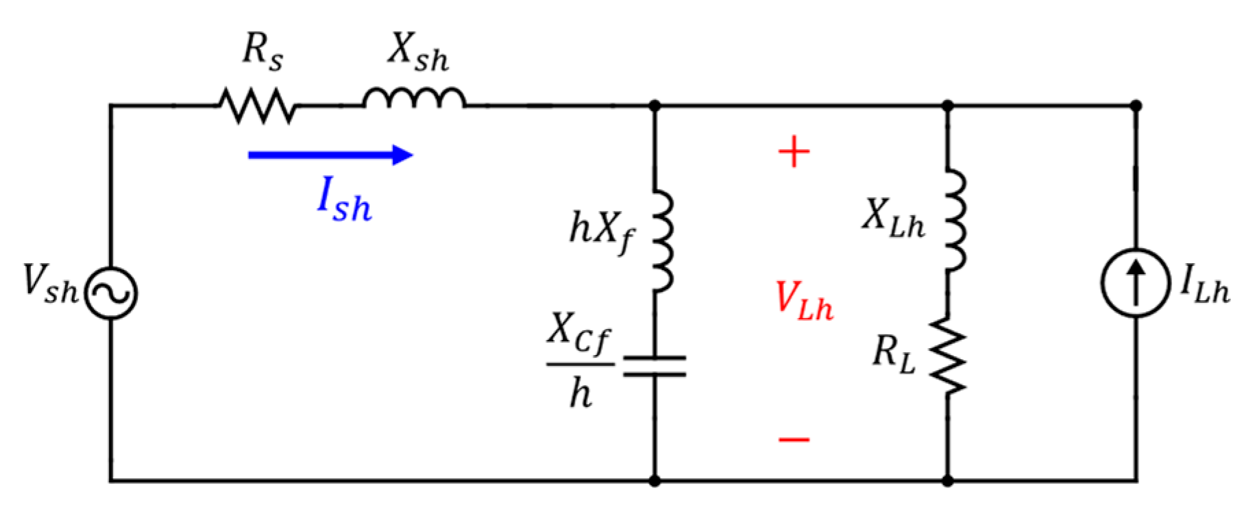
Figure 1 presents the per-phase equivalent circuit of the proposed nonlinear system consisting of harmonic-generating voltage source
and source impedance
with undamped single-tuned filter connected in shunt with nonlinear load represented by impedance
and harmonic- generating current source
at the
harmonic order.
Where the system impedance and the load impedance at the
harmonic order are given by Equations (1) and (2):
And the undamped single-tuned filter impedance
is given as follows,
where
are the inductive reactance and capacitive reactance of the filter at fundamental frequency respectively.
Using the nodal analysis, the
load voltage
and
supply current
for the proposed system are given as follows:
Then the rms values of the load voltage and the supply current could be evaluated as follows,
The performance optimization quantities; PF, PL and VTHD; are calculated as follows:
The complex power (
) and the real power (
) of the nonlinear load are
The compensated power factor (
) [
14] is calculated by
The transmission loss due to the system impedance [
20] is calculated by
The voltage total harmonic distortion
[
3] is:
The capacitor and inductor ratings, which serve as the basis for estimating the total filter cost, are determined through the following calculations [
30], where the first summation term is structured to reflect the cumulative effect of harmonic voltage components, thereby emphasizing peak-related electrical stress on filter elements relevant for insulation and cost estimation.
3. Proposed Firefly Algorithm
The FFA was adopted due to its fast convergence, robust search capability, and reduced dependence on parameter tuning compared to GA, PSO, and ACO. Its ability to avoid local optima through controlled randomness makes it particularly effective for nonlinear, multi-objective filter design problems. There are three rules that applied to idealize the algorithm mathematically are:
Unisex Fireflies: Fireflies are unisex, so any firefly can be attracted to any other firefly regardless of sex.
Attractiveness and Brightness: Attractiveness is proportional to brightness, and both decrease with distance. A less bright firefly will move toward a brighter one. If no brighter firefly is present, it will move randomly.
Brightness and Objective Function: The brightness of a firefly is determined by the objective function’s landscape.
In the FFA, the brightness
of a firefly at location
is defined by the value of the objective function
, i.e.,
. The attractiveness
of a firefly depends on the distance
between fireflies
and
, and is given by (15).
where
is the maximum attractiveness and
is the absorption coefficient. The distance
between fireflies
and
at locations
and
is the Cartesian distance:
At iteration
, the movement of firefly
toward firefly
is determined by (17).
where the term
represents the attractiveness factor, β, while the term
adds randomness controlled by the parameter α, with
being a random number between 0 and 1.
In the context of the proposed optimization framework, each search agent (individual firefly) represents a candidate solution vector defined as are the capacitive and inductive reactances of the filter, respectively. The objective of the algorithm is to determine the optimal coordinates of these agents within the defined search space constraints
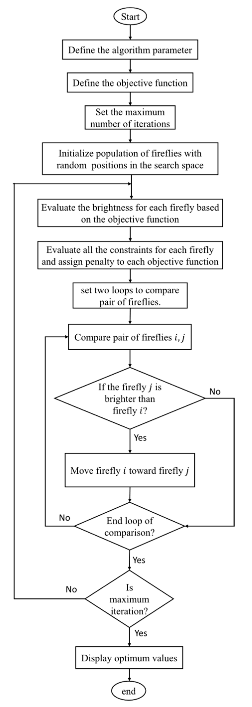
The pseudo code and the flow chart that summarizes the basic steps of the FFA are shown in Algorithm 1 [
31] and in
Figure 2, respectively.
| Algorithm 1. Pseudo code of the FFA. |
Firefly Algorithm
While
for fireflies
for fireflies
Evaluate new solutions and update light intensity
end if
end while
Postprocess results and visualization |
The literature [
32,
33] expose various optimization models of passive filter and active filter planning problems with common multiple objective functions comprised of PF improvement, VTHD reduction and cost minimization.
For multi-objective optimization problems, where multiple conflicting objective functions need to be minimized or maximized simultaneously, and the problem is subject to inequality constraints and equality constraints , the FFA can be adapted to simultaneously optimize our three conflicting objective functions, namely:
The maximization of power factor Equation (10),
The minimization of the transmission power loss Equation (11),
The minimization of the voltage total harmonic distortion Equation (12).
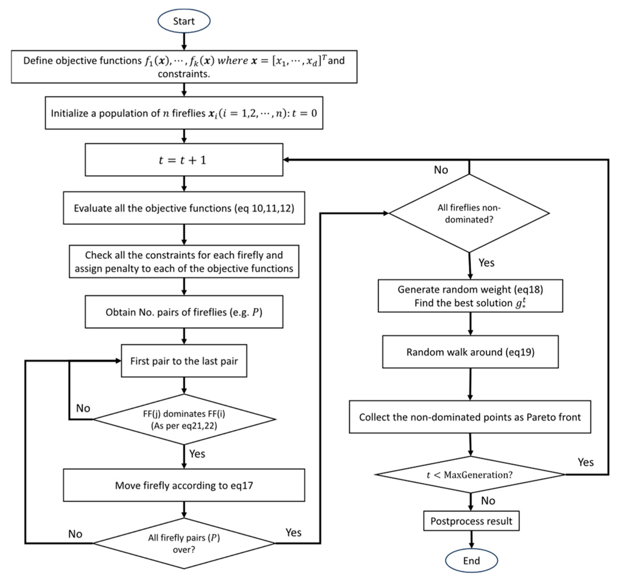
As illustrated in the MOFA flowchart in
Figure 3, the multi-objective firefly algorithm (MOFA) is initialized in the same manner as the standard FFA. Subsequently, a random weight vector is generated such that its components sum to one, allowing a combined best solution
to be obtained. The non-dominated solutions are then carried forward to the next iteration. After a fixed number of iterations, typically
non-dominated solution points are obtained, approximating the true Pareto front.
To conduct random walks more efficiently, the current best solution
is identified by minimizing a combined objective using the weighted sum approach:
It is important to note that the weights
are randomly chosen at each iteration, enabling the non-dominated solutions to sample diversely along the Pareto front. When a firefly is not dominated by others in the Pareto sense, it moves according to:
where
denotes the best solution found so far for a given set of random weights and
is the degree of randomness can be decreased as the iterations progress, as follows
where
represents the initial randomness factor.
In the multi-objective context, dominance is defined as follows: a solution
dominates a solution
if it is no worse in all objectives and strictly better in at least one, as expressed in Equations (21) and (22) [
14]:
A solution is Pareto optimal if is non-dominated by any other for every . The set of all non-dominated solutions forms the Pareto optimal set, and the corresponding objective vectors form the Pareto front. The multi-objective firefly algorithm (MOFA) exploits the concept of Pareto optimality to approximate the Pareto front using the traditional FFA.
It should be noted that no predefined weighting factors are imposed in the optimization process. Instead, the problem is formulated within a Pareto-based multi-objective framework, where the trade-offs between harmonic suppression performance (e.g., VTHD reduction) and filter sizing (represented by the decision variables and ) are inherently captured. This approach generates a set of non-dominated solutions, allowing the natural relationships and compromises between competing objectives to be explicitly revealed without introducing subjective bias through weighting coefficients.
In the present study, it is proposed to design a single-tuned filter optimally according to performance criteria as follows:
Minimization of voltage total harmonic distortion (VTHD)
Minimization of power transmission loss
Maximization of power factor (PF)
To maintain mathematical consistency within the multi-objective optimization framework, which is defined for minimization, the maximization of the Power Factor (PF) is transformed into a minimization objective as
In the proposed FFA, the optimization problem considers the filter parameters as decision variables. Then perform the optimization in two ways as follows,
On the other side, in practical applications, the objective function encounters multiple constraints that impose various limitations on the selection of optimization variables. In the proposed research the constraints are as follows,
According to the IEEE 519-2014 standard [
4], the voltage total harmonic distortion should generally not exceed 5% at the point of common coupling (PCC) to ensure the reliability and performance of electrical systems.
PF should be equal or more than 90% at PCC. Low PF may cause some utilities to impose a reactive power tariff as a financial penalty to mitigate these issues, promoting better power factor management among consumers [
34].
For practical consideration, the two decision variables
of the optimization problem are restricted within specific bounds according to Equations (23) and (24).
4. Simulation, Results and Discussion
In the present research, two distinct industrial plants cases with different short circuit levels are tested. The power associated with the inductive three-phase load and reactive power are specified as 5100 kW and 4965 kVAR, respectively. The supply bus voltage operating at a frequency of 60 Hz is quantified at 4.16 kV (line-to-line) with a displacement power factor of 71.65%. All pertinent data were primarily extracted from the IEEE Std 519-1992 publication.
Table 1 lists all the system parameters and harmonic levels. All simulations were conducted using MATLAB R2019b on a system equipped with an Intel
® Core™ i7-3520M processor (Intel Corporation, Santa Clara, CA, USA) (2.90 GHz) and 8 GB of RAM.
Table 2 shows the parameters used in simulation of proposed FFA. The maximum number of iterations is assumed to be 100. Results of proposed FFA with a single objective function based on one of the following performance criteria; maximization of power factor (PF), minimization of power loss (Ploss) and, minimization of VTHD; are shown in
Table 3.
Results show that all values of optimized quantities are within the proposed constraints. It is clear that the improvement in VTHD affects both PF and PLoss since minimization of VTHD requires more harmonic currents. On the other hand, the improvement of PF is mirroring to transmission loss reduction since as PF is improved the absorbed current is reduced resulting in lower loss. Also, it is clear that as the short circuit level is reduced the improvement in system performance is affected since the system impedance increases.
For a fair comparison, the computational settings of the proposed FFA and the MIDACO method were carefully aligned. The parameters of the FFA are listed in
Table 2, while the MIDACO settings were adopted directly from [
20]. Both methods were evaluated under identical system configurations, constraints, and stopping criteria. Accordingly, the comparison is based on the best-achieved objective values, convergence behavior, and computational time, providing a consistent basis for evaluating the relative performance of the two optimization approaches.
Based on the comparison of the obtained results and the results of the paper [
20] outlined in the
Table 4, the single-objective firefly algorithm, seeking to optimize each objective function independently, outperforms the Mixed Integer Distributed Ant Colony Optimization (MIDACO) given in the paper [
20]. These Comparative results reveal that the steady state design of proposed FFA achieves enhanced performance relative to MIDACO, such that the FFA gives a VTHD approximately half that of MIDACO, and demonstrates a considerable improvement in PF and Ploss.
For multi-objective optimization function,
Table 5 shows the obtained results of the Pareto optimal front for power factor (PF), power loss (Ploss) and, VTHD in which Ploss, VTHD and, PF are optimized collectively using multi-objective firefly algorithm. The fitness function depends on performance measurements. Results show the inverse proportionality between both of PF and Ploss in a side and VTHD in the other side. As VTHD is reduced both of PF and Ploss are reduced. In future cost could be proposed to be the fitness function and hence the most economical design could be by combining all performance in terms of cost function.
The performance evaluation of the proposed FFA and Multi-Objective Firefly Algorithm (MOFA) reveals significant improvements in power quality indices compared to conventional optimization techniques. The single-objective FFA successfully minimizes power loss, reduces VTHD, and maximizes PF individually. In the first case study, FFA reduced power loss to 5.76 kW, minimized VTHD to 1.32%, and improved PF to 99.22%. In comparison, the MIDACO method resulted in 6.12 kW power loss, 2.34% VTHD, and a PF of 97.18%. A similar trend was observed in the second case study, where FFA outperformed MIDACO across all metrics.
The MOFA approach provides a set of optimal solutions on the Pareto front, allowing system designers to balance competing objectives. For instance, a compromise solution in Case 1 achieves a PF of 98.85%, power loss of 5.84 kW, and VTHD of 4.16%. This flexibility in optimization ensures that industry requirements and constraints can be met effectively.
Additionally, the proposed FFA-based optimization exhibits a significantly faster convergence rate compared to MIDACO. The FFA completed optimization in an average of 0.38 s per iteration, whereas MIDACO required approximately 17 s, demonstrating the superior computational efficiency of FFA.
The results validate the effectiveness of FFA and MOFA in designing STPFs with improved harmonic mitigation, reduced losses, and enhanced power factor. These findings suggest that FFA-based optimization offers a robust and efficient alternative for passive filter design in industrial power systems, ensuring compliance with IEEE 519-2014 standards [
4], while maintaining operational efficiency.
Finally, the proposed algorithm’s performance is evaluated based on the optimal values for capacitor and inductor reactance in the design of a STPF as steady state solution and the convergence time. The primary objectives are to maximize power factor, minimize power loss, and reduce voltage total harmonic distortion within a considered power system. According to the set-up parameters used for a single-objective FFA in
Table 2, the
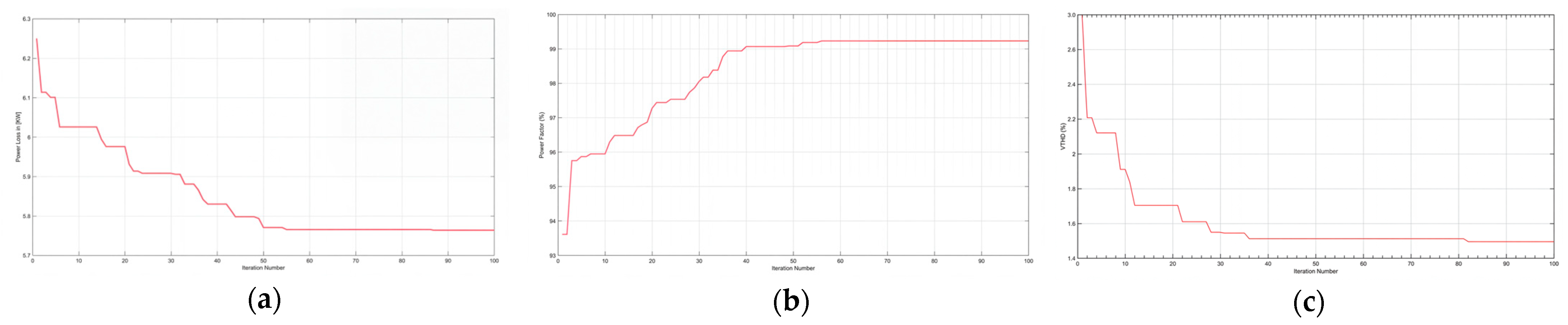
Table 6 illustrates the quantitative analysis of the proposed algorithm performance. The
Figure 4 shows the rate of convergence of the proposed FFA.
In a comparison with the Mixed Integer Distributed Ant Colony Optimization (MIDACO) method proposed in [
20] in terms of the computation time and number of iterations. The comparison results in
Table 7 show that our FFA outperforms the Mixed Integer Distributed Ant Colony Optimization (MIDACO) in convergence time and the used number of generations. The results validate the effectiveness of FFA in solving complex power system optimization problems, making it a promising approach for passive filter design.
For a broader perspective on the comparative performance of the proposed MOFA, the study in [
14] shows that a Pareto-based Firefly Algorithm outperform established multi-objective optimization techniques such as NSGA-II and MOSMA in terms of convergence characteristics and solution diversity. In the present study, the proposed FFA/MOFA framework demonstrates superior performance compared to the MIDACO method for the same case studies, as evidenced by improvements in PF, VTHD, and power loss shown in
Table 4. Moreover, MIDACO itself has previously been reported to outperform conventional approaches such as GA and PSO for this filter design problem [
20]. Accordingly, the obtained results further confirm the effectiveness and competitiveness of the proposed optimization framework.
5. Cost Analysis for the Proposed Design
Installing a PPF to mitigate harmonics and ensure compliance with IEEE 519-2014 standards involves significant capital expenditure. However, the resulting improvement in system performance justifies this investment, particularly due to the enhanced PF and consequent reduction in power losses.
To provide a quick assessment of the economic feasibility of PPF implementation, we analyze the costs associated with filter reactance and capacitance components in relation to the Egyptian electricity tariff (2024). This study quickly evaluates the financial benefits for industrial consumers, considering both operational efficiency gains and potential cost savings.
A concise breakdown of the Egyptian tariff structure (2024) [
35] for industrial consumers
- 1.
Demand Charge
Calculated based on the highest value among:
- ○
The contracted power in kW,
- ○
90% of the contracted power in kVA, or
- ○
The actual measured power in kW.
Cost: 720 Egyptian pounds (LE) per kW per year.
- 2.
Consumption Charge
Based on total energy used (kWh).
Cost: 1.94 LE per kWh.
- 3.
PF Adjustments
Penalties for Low PF (below 0.9):
- ○
If PF is between 0.7 and 0.9: Penalty = (0.9 − PF) × (kWh charges).
- ○
If PF drops below 0.7: Penalty = [0.2 + 1.5 × (0.7 − PF)] × (kWh charges).
- ○
If uncorrected after 3 months, the penalty doubles.
- ○
Service may be disconnected if PF remains low for over 6 months.
Bonus for High PF (above 0.92):
- ○
Bonus = [(PF − 0.92)/2] × (kWh charges).
This structure incentivizes industries to improve PF and manage demand efficiently, with potential savings from reduced penalties, lower demand charges, and operational benefits like decreased energy losses.
The PPF component costs are estimated at 500 L.E/kVAR, using Equations (13) and (14), the filter cost is:
For the case study plant, with the same system parameters for case 1, operating at 1300 kW with a 90% PF (630 kVAR compensation), the economic benefits of installing a PPF can be quantified across four key dimensions [
30]:
- 1.
Reduction in Power Demand Charges
Saving:
Where:
- ○
(original contracted power)
- ○
Reduced demand after STPF installation.
- 2.
Energy Cost Savings from PF Correction
Saving: [Old kWh charges − New kWh charges] 1.94 LE/kWh
- 3.
Elimination of PF Penalty
Saving:
- 4.
Bonus for Overcorrection (PF > 0.92)
Bonus:
Where we assume that the continuous operation of the load (8766 h/year = 24 hrs/day × 365.25 days)
The Total Annual Savings, formulated by combining all components, serves as the objective function to be optimized, maximizing economic benefits while meeting system constraints, given as:
The Payback period (PT)—the time required to recover the initial investment—is a critical metric for evaluating economic feasibility. It is calculated by Equation (27).
Based on the case study data presented in
Table 1, optimization of the Total Annual Savings Equation (26) using the FFA under the specified constraints.
Table 8 demonstrates that PPF installations consistently achieve full PT within one year. This rapid return on investment underscores their strong economic viability and attractiveness for industrial consumers.



 and
and