Abstract
This paper introduces an efficient computational procedure for analyzing the propagation of harmonic waves in layered elastic media. This offers several advantages, including the ability to handle arbitrary frequencies, depths, and the number of layers above an elastic half-space, and efforts to follow dispersion curves and flag up possible singularities are investigated. While there are inherent limitations in terms of computational accuracy and capacity, this methodology is straightforward to implement for studying free or forced vibrations and obtaining relevant response data. We present computations of wavenumber dispersion diagrams, phase velocity plots, and response data in both the frequency and time domains. These computational results are provided for two example cases: plane strain and axisymmetry. Our methodology is grounded in a well-conditioned dynamic stiffness approach specifically tailored for deep-layered strata analysis. We introduce an innovative method for efficiently computing wavenumber dispersion curves. By tracking the slope of these curves, users can effectively manage continuation parameters. We illustrate this technique through numerical evidence of a layer resonance in a real-life case study characterized by a fold in the dispersion curves. Furthermore, this framework is particularly advantageous for engineers addressing problems related to ground-borne vibrations. It enables the analysis of phenomena such as zero group velocity (ZGV), where a singularity occurs, both in the frequency and time domains, shedding light on the unique characteristics of such cases. Given the reduced dimension of the problem, this formulation can considerably aid geophysicists and engineers in areas such as MASW or SASW techniques.
1. Introduction
The primary objective of this paper was to investigate the propagation of elastic waves in a waveguide from a rigid strip or a rigid disk placed on the surface of a two dimensional or axisymmetric three-dimensional layered semi-infinite space. Importantly, this study aimed to achieve this without the need for extensive layer subdivisions, even for deep layers. Our research builds upon the findings presented in a prior work (reference [1]), which provided a scaled dynamic stiffness matrix for bedrock layers. While extending this bedrock problem to a half-space formulation is relatively straightforward and requires minimal additional analysis, the novelty of our work lies in its practical applications. For exceptionally deep strata, we demonstrate that a path continuation methodology can identify an internal zero group velocity resonance, and the corresponding time domain solution vividly illustrates the resonance behavior. It is worth noting that larger and more complex models would yield the same results, but what sets our approach apart is its ability to achieve these outcomes with manageable computational demands, even on standard PC desktops.
The ground is modeled as a soil profile that consists of multiple elastic, homogeneous, isotropic layers. This problem has seen much activity in the past three decades but this formulation contains a novel approach to determine a dynamic stiffness matrix. What is new, but comparable to previous studies in this area, is the computation of natural modes of free vibration for very deep strata, which may be computed easily and used for further physical analysis. These are usually used to help explain a forced response calculation due to harmonic or seismic loads in the body of the ground, wherein an example related to a harmonic rigid-surface disk load is presented. Since the formulation is related primarily to P-SV wavetypes we will drop most references pertaining to either the plane strain or axisymmetric problems, where it is understood that the formulations can be applied to both cases. At the end of the paper, a forced-vibration result presented in terms of the time and frequency domains is presented for an axisymmetric problem.
Ground vibration literature contains a wealth of publications, with much work having been conducted on the natural propagating modes in a layer over a half-space. The case of a fluid layer over a higher-velocity fluid half-space is less complicated than the elastic wave problem; it was first investigated by [2], and it is well-known as one of the first attempts to study wave propagation through layers with overly infinite domains. Although the domains lacked shear wave coupling, Ref. [2]’s thorough analysis showed that unattenuated propagation of sound would occur in a slower fluid layer characterized by the minimization of something called ’the group velocity’. The group velocity basically indicates the speed at which the amplitude or envelope wave “groups” progress in a medium. Importantly, if the group velocity is constant then the wave propagation is commonly called non-dispersive, which means that all waves progress at the same speed. In layered media, where wave speeds vary between layers, group velocity is clearly non-constant, and wave propagation analysis, although linear in nature, is complicated to analyze.
Currently, elastic wave propagation analysis is usually performed via the [3] stiffness matrix method (SMM). This approach was devised based on the earlier transfer matrix method (TMM) originally proposed over 70 years ago by [4], later corrected and elaborated by [5], and iterated further by [6,7] relatively recently. Dunkin [8] also obtained modal solutions by using the TMM. As was pointed out by Roesset, and more recently by Kausel [9], the SMM has several advantages over the TMM approach: (i) the global stiffness matrix becomes symmetric in the SMM and, as a result, lesser storage is required and also fewer operations are required for executing the analysis; (ii) various loading profiles can be easily treated; (iii) sub-structuring techniques become readily applicable. In the SMM approach, two different methods exist, namely, (i) the exact approach based on the root search method (RSM), and (ii) the approximate thin layer method (TLM) based on a quadratic eigenvalue formulation. In the exact approach, while forming the global stiffness matrix, the contribution of each layer is duly incorporated without making any approximation. However, while obtaining the solution using the RSM, since the exact approach contains a number of hyperbolic and transcendental functions the solution can be obtained only by trial and iterative procedure. Tan has also described how to increase accuracy for multilayer problems [10,11], Ba et al. have described efficient methods applied to porous layers [12], and Huang et al. have formulated a two-step solution combining solutions in the Fourier and spatial domains [13].
The model considered here demonstrates the effect of a harmonic finite load over layered strata [14]. The results derived by Fourier transform are valid for any frequency and, importantly, any depth of layer. In principle, following traditional methods [15], we could have used displacement and stress-continuity boundary conditions at the bottom of the layer with equations at the ground surface to generate equations for four subsequent unknowns of stress and displacement. However, this direct approach leads to formidable numerical problems, in part due to fundamental expressions for characteristic wave functions, such as cosh or sinh, which, when employed, can have a dramatic effect on the numerical evaluation of solutions. Moreover, problems can arise due to the cancellation or division of either very small or very large numbers [16]. To overcome this, ref. [17] derived a well-conditioned propagator matrix (TMM) for radially symmetric problems. In this work, though, we constructed a single stiffness matrix method (SMM) for the physical layer for plane strain problems, which conveniently avoids these difficulties. We therefore proceeded in the establishment of an original global dynamic stiffness matrix using expressions that do not cause numerical problems.
A scaled dynamic stiffness matrix for an arbitrary thick layer was derived. To achieve this, the vibration components in the wavenumber domain for layer depths and a half-space were considered and arranged into a single matrix formulation. For the forced response, the load was modeled as an infinite strip, so that the problem was plane; for the axisymmetric case, the matrices were almost identical, so for a rigid uniform disk loading the vertical and radial responses could also be calculated by an inverse transform, noting that a Hankel transfom requires inversion in the axisymmetric case. Nevertheless, the overall purpose of the present study was to present a computational method that does not suffer numerical evaluation difficulties when predicting vibration transmission, in particular its attenuation on the surface of a deep layer. The usefulness of the method is illustrated by presenting numerical results from potentially computationally intensive application examples. Comparisons against numerical solutions using finite element methods (FEM) or boundary element methods (BEM) have been successfully performed previously but we wished to avoid details of truncation, convergence, or element type that might detract from the essence of this work.
This paper, which focuses on determining solutions for free- and forced-wave propagation problems, is structured as follows: In Section 2, we establish the scaled formulation of the problem for both plane strain and axisymmetric coordinates in the wavenumber domain. This section also provides a brief overview of the root-finding methodology. Subsequently, we present a numerical example that verifies the free-vibration formulation derived by previous researchers. Additionally, in a second example, we identify the presence of zero group velocity modes, which are associated with a well-known earthquake study. Section 3 includes frequency and time domain simulations, specifically addressing a stationary rigid disk load. Finally, in Section 4, we offer a summary of our findings and draw conclusions to wrap up the paper.
2. Computational Model
In this section, the well-known methodologies related to free and forced vibration are formulated for plane strain or axisymmetric cases.
2.1. Two Dimensional and Axisymmetric Models
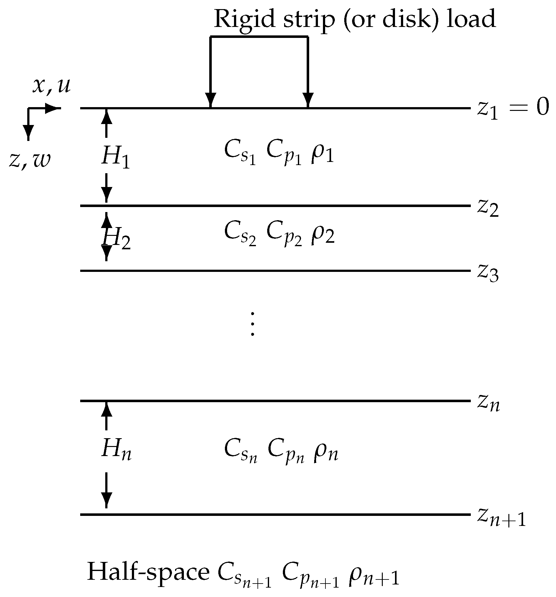
A generic model considered is shown in Figure 1. A strip load has width and is aligned with respect to the z-axis. It rests on a homogeneous, isotropic, elastic layer, with material properties E (Young’s modulus), (mass density), and (Poisson’s ratio). A harmonic vertical rigidly supported load acts uniformly over a strip situated above elastic layers. The elastic layers of finite depth consist of homogeneous and isotropic material, overlying an infinite half-space of flexible material. The model is two dimensional, and the co-ordinate system and parameters are shown in Figure 1. Although two dimensional, the methods used here cover plane strain and axisymmetric cases. This figure shows a generalized example of a semi-infinite stratified soil profile with linear elastic layers. For computation of theoretical dispersion curves corresponding to the assumed layer structure the problem assumes plane strain in the plane. The x-axis is taken parallel to the layers, with the x-axis in a horizontal direction to the surface wave propagation. The positive z-axis is directed downwards. To develop an axisymmetric model, we referred to [18] for inspiration.
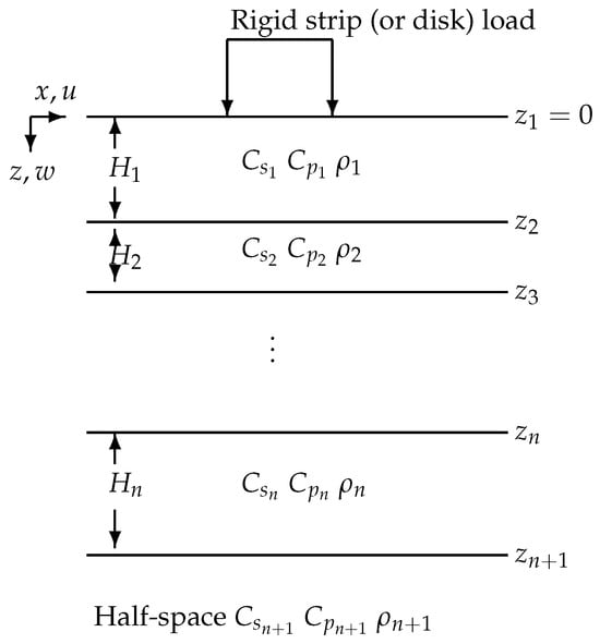
Figure 1.
A layered half-space model geometry. The parameters of the model are shear and pressure wave velocities , , respectively, in each layer, with mass density and layer thickness .
For plane strain conditions much of the analysis necessary for the derivation of the dynamic stiffness matrix has been presented before in references [14,15,19], so this will only be briefly summarized. For plane strains the behavior of the elastic material is described by Navier’s elastodynamic equations [14]. Without loss of generality, in the absence of body forces, these equations apply to any layer and are written in vector form as follows:
where represents the components of the displacement in the x and z directions and , are the Lamé constants. For the free-vibration problem the boundary conditions for the layered problem are as follows: [(a)] zero stresses at the surface, so on , [(b)] continuity of displacement and stress at internal interfaces, and in the far field, [(c)] displacements as . The quantities and are, respectively, the pressure (P) and shear (S) wave speeds given by
Note that the boundary conditions are almost identical for the axisymmetric problem in , but on the surface whereas over a disk of radius b or half-strip length b for the forced vibration in axisymmetry and plane strain, respectively.
The non-symmetric and complex-valued matrix , Appendix B, and the steps required in its derivation are given in [1]. Specifically, is the dynamic stiffness matrix for a single elastic layer that is valid for any depth . To include the half-space in the formulation, we consider the addition of a complex element stiffness matrix, :
such that
where and at the lowest interface and . Due to the way in which the ordering of the stresses and displacements are conveniently organized, the stresses and tractions at any interface cancel so that the load vector on the right-hand side is zero except for stress that accounts for surface load. The element matrix equations obtained for each layer of the soil model are subsequently assembled at the common layer interfaces to form the global layered system. The stiffness matrices for each layer can now be combined to give a single matrix equation for an elastic layer over an elastic half-space, involving the scaled stiffness matrix for the elastic layers , and the matrix for the half-space .
Hence, it is straightforward to generalize this technique to n elastic layers supported by an elastic half-space where the size of the dynamic stiffness matrix becomes a single complex-valued matrix, but remembering that the matrix entries are transcendental in wavenumber k. The right-hand side now only involves transformed stresses at the ground surface, since the neighboring interface values have canceled each other, as discussed earlier:
Kausel and Roesset, in [3], previously introduced an alternative formulation using a transfer matrix method (TMM) approach with stiffness matrices (SMM) akin to those employed in structural dynamics. An element stiffness matrix, denoted as , is derived for each layer within the geodynamic model. This element stiffness matrix for a specific layer relates the stresses at the upper and lower interfaces of the layer to the corresponding displacements. In the case of a multi-layered model, the system stiffness matrices, combined with prescribed load vectors, can be employed to solve for displacements using techniques analogous to the standard finite element method. When a load is applied to the surface, the transformed stresses become non-zero, allowing the matrix Equation (6) to be solved in spatial wavenumber.
Apart from a slight change in the transformed values for the displacements, identical expressions are obtained in the axisymmetric P-SV case. Hence, it is straightforward to compute plane strain propagating and axisymmetric P-SV propagating modes in the free-vibration case.
2.2. Free Vibration
To consider free vibration for the layered half-space problem the right-hand side of Equation (6) is zero, and, hence, we have the following expression:
where the matrix has been defined above (see Equation (5)) and the unknowns are the displacements on interfaces. Non-trivial solutions of Equation (7) are found by equating the determinant of the matrix to zero. The non-zero solutions or eigenvectors of this equation give the actual (real-valued) u and w displacements representing the propagating modes (for real wavenumber solutions) through a vertical cross-section.
For calculations for the response of a layered half-space to a surface loading, the transformed loads in the plane strain and axisymmetric P-SV are not identical nor are the inverse transforms that need to be evaluated.
2.3. Forced Vibration
In the plane strain case, the transformed load on the surface is represented as a traction. In both cases of plane strain and axisymmetry, responses at points on the surface of the ground can be recovered by employing suitable quadrature to the products of the displacements in the wavenumber domain and the transform kernel. The solution of the system of Equations (6) yields the transformed displacements at the surface and, hence, by suitable inverse-transformations solutions can be obtained. The response in the space-frequency domain is obtained by an inverse transformation from the wavenumber to the spatial domain, as outlined in [18], where
2.4. Numerical Evaluation of the Dynamic Stiffness Matrix
In general, when dealing with non-dimensional wavenumbers where (with representing the shear wavenumber), the conventional approach encounters difficulties. Specifically, when the depth exceeds approximately six shear wavelengths (), a numerical bottleneck problem arises when attempting to solve the system of linear algebraic equations. Additionally, high-frequency computations can become ill-conditioned. It is important to note that results cannot be reliably presented in cases where a “bottleneck” occurs or is imminent since matrix elements may become unbounded.
To overcome the challenges associated with the global coordinate system, we introduce a set of local coordinate systems to characterize vibrations within layered media. This approach is designed to address bottleneck issues as outlined in [16].
In this work, the necessary manipulations to provide a robust scaled matrix, as a projection method, have already been performed to assist in coding the matrix. The utilization of the projected method ensures stable numerical evaluations for stiffness matrix entries, thereby mitigating concerns related to numerical round-off errors. This is particularly crucial when dealing with operations such as dividing large numbers by small ones or subtracting very large numbers. For instance, round-off errors can lead to exponential growth in relative errors when evaluating the difference between functions like , where and the difference is small. Additionally, the numerical assessment of hyperbolic functions such as cosh and sinh can pose challenges when handling large argument values.
2.5. Root Finding and Parameter Continuation
Considering free vibration, the expression, Equation (7), may be written succintly as
where each entry in the stiffness matrix represents a nonlinear function in terms of the spatial wavenumber k and frequency , giving rise to a nonlinear root-finding exercise when non-trivial solutions are sought. While we shall not delve into the specifics of the function itself, our focus is on locating its roots. To achieve this, the method described below is employed to identify the roots of the determinant , denoted as and commonly called the dispersion equation. A notable consequence of this approach is that the phase velocity for any propagating mode can be easily derived for points along the dispersion curves where
A root-finding routine has been implemented, utilizing the complex plane winding number integral to verify the count of real roots for systems such as Equation (11). These routines for root finding in the complex plane rely partly on the application of the complex-argument principle.
Wave propagation frequencies or wavenumbers, along with their associated modes carrying energy, can be readily evaluated by determining the value of the roots of Equation (11). Numerous methods are available for finding roots or zeroes of nonlinear functions in one or multiple variables. However, the root-finding algorithm employed in this study is based on the procedure developed by Ivansson and Karasalo [20]. Further elaboration on the specific details of this algorithm will not be provided here except to mention that no sophisticated strategy for determining the initial guesses for the solvers was adopted. For example, at a specific frequency of interest the winding number integral determines the number of roots in a domain, and a suitable nonlinear solver finds all these roots. Supposing 10 distinct roots have been found, then 10 curves are followed, using the continuation process outlined below.
Instead of seeking all the roots of the dispersion Equation (11) in a step-by-step manner through stepping in one of the parameters, a technique different from more traditional methods has been adopted. This approach proves effective in systematically seeking roots along curves in -space. The method involves tracing dispersion curves through a parametric continuation approach by using previous roots as initial estimates. In this context, the parameter can be either the frequency or, alternatively, the wavenumber k. For simplicity, let us assume all the roots, , at step i have been found and that the roots are now sought at the next frequency, , where, in the case of constant steps, . If is sufficiently small, and using simple linear extrapolation to determine an initial estimate ,
then we should expect to find solutions, , of Equation (13) efficiently:
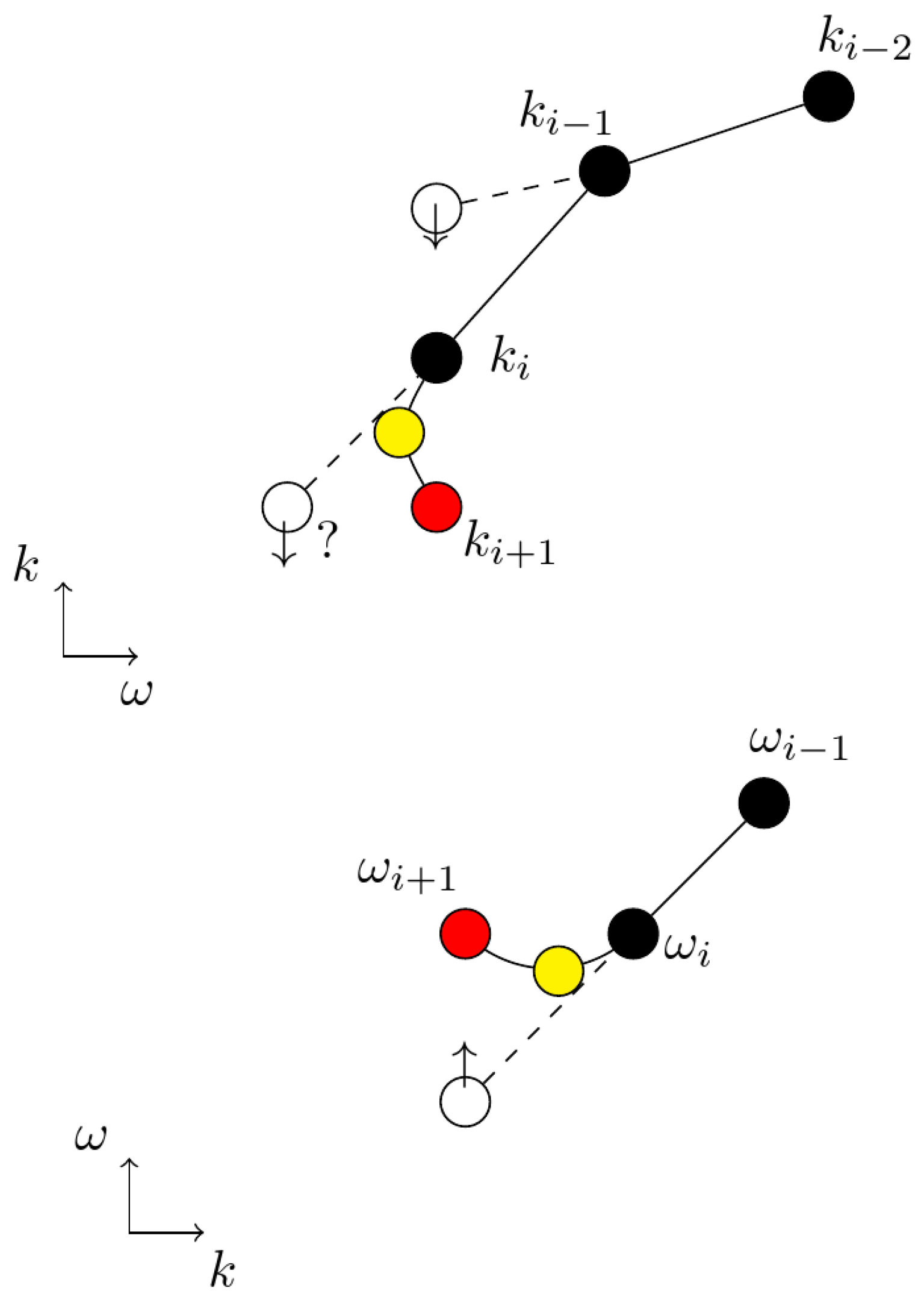
This method works well while the dispersion curves are slowly varying; moreover, continuation for all the roots simultaneously is possible, but when a steep slope is encountered an adaptive technique for individual curves is required. A basic alternative formulation yielding variable (usually smaller) step sizes, , which are inversely proportional to the rate of change of the slope at previous steps, appeared to yield convergent results, while also flagging up possible fold points. Further research into adaptive methods, polynomial extrapolation, or arc continuation is continuing. However, this simple approach introduces an additional layer of flexibility and proves highly effective, especially when each frequency corresponds to a predetermined fixed number of single roots. Currently, we focus on tracing a single set of curves in terms of frequency, as illustrated in the upper plot, Figure 2.
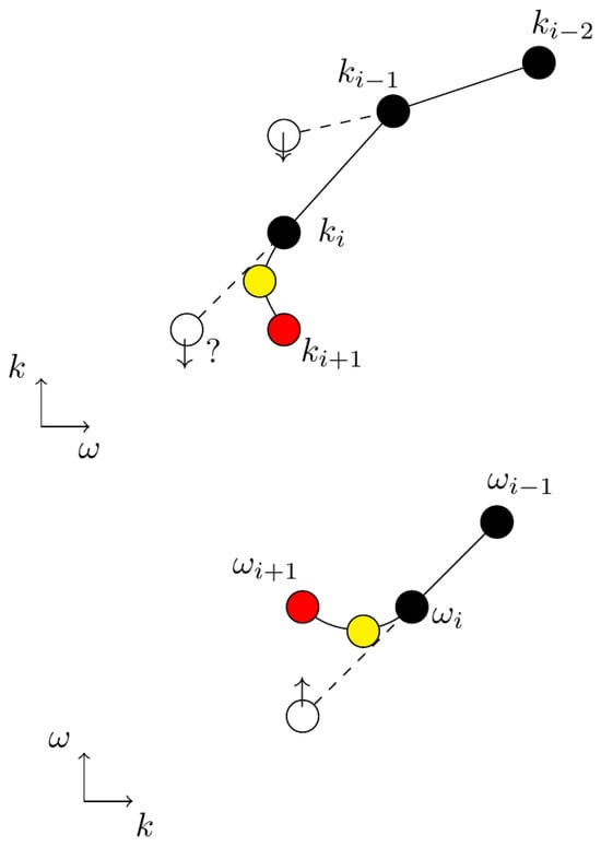
Figure 2.
Sketch showing a turning point or fold/branch bifurcation. A white dot represents the initial guess for the solver, the red dots show the true solution, and the yellow dots show the ZGV turning point. The black dots represent previously computed solutions.
Once a warning occurs, interchanging the parameters and k in the dispersion equation means practically that fixing values of the frequency can lead to solutions of the dispersion equation in k (11). Hence, if is small we expect to find solution curves in . In other words, continuing the solution path in either or k, as a means to obtaining solutions of Equation (13) efficiently.
The methodology of interchanging is a powerful technique that requires automating in the present algorithm. In the next section, the idea of parameter continuation is proposed as a means to increase speed for computing relevant curves. Each curve is determined by the roots of a specific formulation.
3. Numerical Examples
Surface waves, except for Rayleigh waves on an isotropic half-space, exhibit a phenomenon called dispersion, where the apparent velocity along the surface varies with frequency. When seismic sources generate waves, they contain a range of frequencies, and each frequency component has its own velocity, known as the phase velocity, denoted as c(). If we were dealing with a single-frequency (monochromatic) wave, we would only need to consider the phase velocity for that specific frequency to fully characterize the disturbance. However, in real scenarios, waves of multiple frequencies interfere with each other, creating constructive and destructive patterns that influence the overall ground motion. These constructive interference patterns behave as wave packets, which themselves propagate along the surface with well-defined group velocities, represented as U(). Therefore, the phase velocity is primarily determined by medium properties (such as layer thickness, intrinsic P and S velocities, rigidity, etc.) and how well a particular harmonic component fits into the associated boundary conditions. This was discussed in the previous section. On the other hand, the group velocity depends on both medium properties (through their influence on phase velocity) and how phase velocity varies with frequency. This variation controls the interference between different harmonics. The group velocity is especially significant because energy mainly propagates within the constructively interfering wave packets, which move at the group velocity rather than individual phase velocities.
Additionally, there are backward waves, which are guided waves with opposite phase and group velocities, causing the phase to move toward the wave source. The study of backward waves dates back over a century, beginning with Lamb’s pioneering work in 1904 [21]. A characteristic feature of a backward-wave mode is a distinctive bend in the dispersion curve with a negative slope, resulting in the negative group velocity of the corresponding guided wave. At the lowest frequency within the backward-wave range, the group velocity becomes zero while the wavenumber remains non-zero, leading to what we call a zero group velocity (ZGV) mode.
The detailed physics of situations involving negative group velocities is not discussed here but is exemplified through example results in both the time and frequency domains, drawn from the existing literature. To validate the accuracy of the method, several scenarios are compared in the examples presented. It is important to note that these scenarios are not considered benchmark solutions as no such benchmarks exist, to the best of the authors’ knowledge. Instead, they serve to illustrate the formulation’s efficiency in terms of computational speed. The soil characteristic values used in these examples are provided for reference in two cases.
3.1. Free Vibration–Dispersion Relations
An application of the free vibration, Section 2.2, is to aid understanding of characteristics that show up for a forced-response case. In this respect, Figure 3 and Figure 4 show the principal results for the ground profiles, Table 1 and Table 2. Verification of the method in the first example and demonstration in the second example of the “unusual” ZGV behavior mentioned above is presented. To show the accuracy and effectiveness of the proposed technique, we proceed to evaluate the dispersion relation and phase velocity spectra for the two ground profiles.
3.1.1. Verification of Model, [22]: Example 1
A ground profile was chosen in the thesis by [22], which was further evaluated by [23], Table 1 using various popular approaches. The ground profile is made up from four different layers, each km in depth, and of a semi-infinite space, with the second and fourth softer layers sandwiched by stiffer layers. Generally, the stiffness of the layer and mass density vary non-uniformly with depth and the shear wavespeeds vary from = 2.7 km/s to = 4.7 km/s for the half-space.

Table 1.
Material properties for Example 1. Referenced in Kumar et al. [23].
Table 1.
Material properties for Example 1. Referenced in Kumar et al. [23].
| Soil | Layer 1 | Layer 2 | Layer 3 | Layer 4 | Half-Space |
|---|---|---|---|---|---|
| Depth (km) | 1.0 | 1.0 | 1.0 | 1.0 | ∞ |
| E (Pa) | |||||
| (kg m−3) | 2700 | 2500 | 3100 | 2900 | 3300 |
| 0.33 | 0.33 | 0.33 | 0.33 | 0.33 | |
| (m s−1) | 3542 | 3262 | 4100 | 3821 | 4380 |
| (m s−1) | 3800 | 3500 | 4400 | 4100 | 4700 |
| (m s−1) | 7544 | 6948 | 8735 | 8140 | 9331 |
There is little physical information included in this referred example but the computations are quite extensive due to the depths of the layers involved, the present method requiring inversions of 10 × 10 matrices; hence, this example was chosen for computational reasons. Figure 3 was produced by the root solver described in Section 2.5, and by digitization of the curves presented in Kumar and Naskar it was possible to reproduce the phase velocity curves presented.
It was not possible to directly compare the accuracy or computation times between Kumar and Naskar and the Kausel method for this single example, but working on an i5 processor 32MB RAM machine running MATLAB 2020A calculation software the tasks were clocked. Here, wavespeed variation with frequencies at 140 equal frequency steps, between 0 and 9 Hz, for the first nine natural modes were computed. Adopting the root-finding method beginning at 9 Hz and ending at 0.1 Hz, the method adopted here took approximately 12.0 seconds to complete the 140-frequency-step analysis. The half-space shear wavespeed is shown as a line across the graph, to show the limit of the solution. It is clear that all three methods agree well.
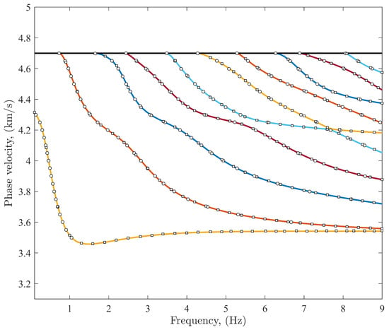
Figure 3.
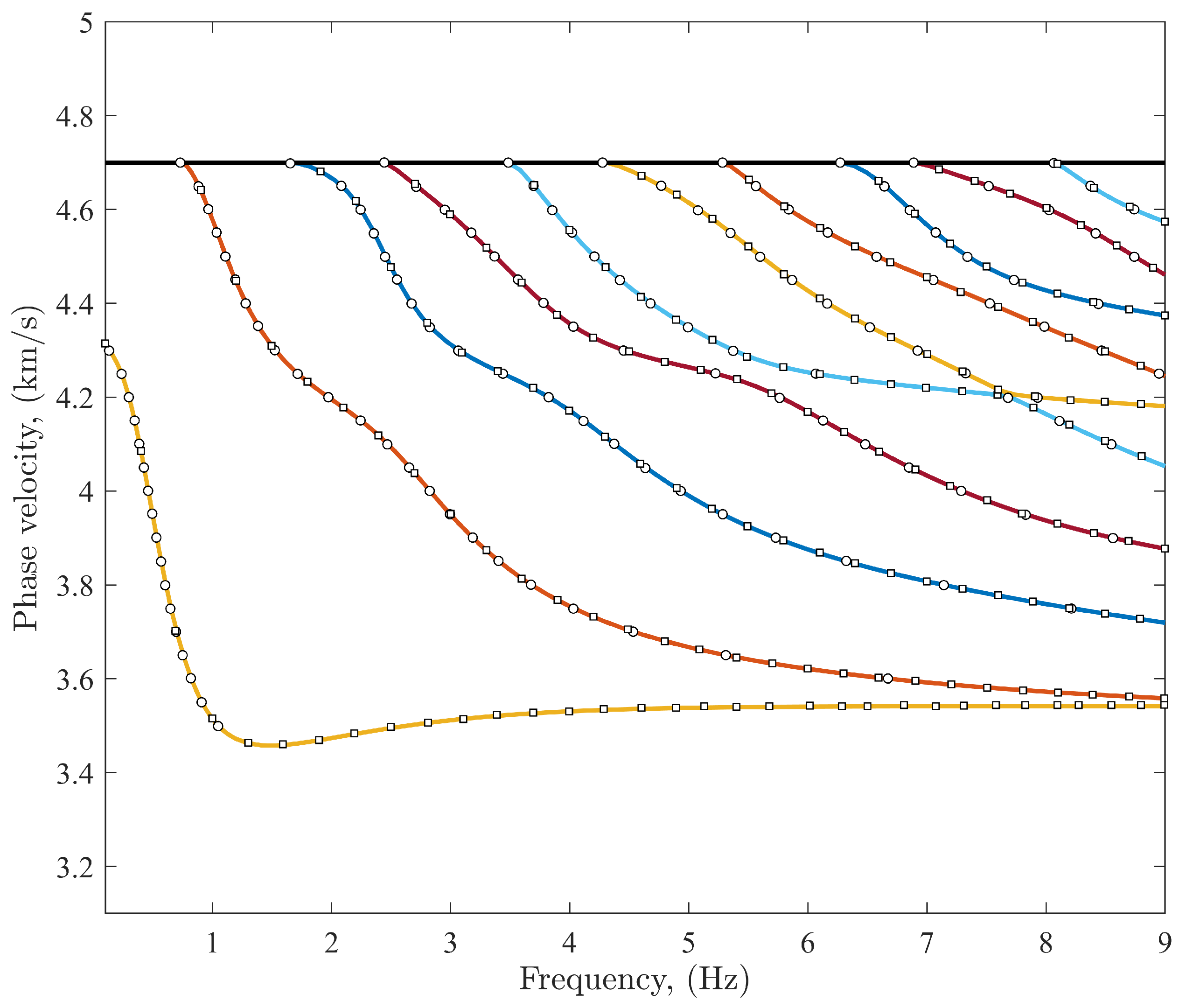
A comparison between the dispersion phase velocity curves calculated by the present method (solid colored lines), with [23] (∘), and by [3] (□). The ground profile comprises four layers of depth km each situated over an elastic half-space, Table 1, referenced as Profile C in Kumar and Naskar [23].
3.1.2. Verification of Scaled-Matrix Technique, Latur Earthquake: Example 2
A ground model site, Table 2, used for synthetic seismograms observed as aftershocks of the Latur earthquake, 1993, was evaluated in paper [6].

Table 2.
Material properties for Example 2, referenced in Wang [6].
Table 2.
Material properties for Example 2, referenced in Wang [6].
| Soil | Layer 1 | Layer 2 | Half-Space |
|---|---|---|---|
| Depth (m) | 5 | 300 | ∞ |
| E (Pa) | |||
| (kg m−3) | 1300 | 2500 | 2700 |
| 0.486 | 0.250 | 0.240 | |
| (m s−1) | 190 | 2392 | 3216 |
| (m s−1) | 200 | 2600 | 3500 |
| (m s−1) | 1200 | 4500 | 6000 |
It consists, simply, of two layers overlying an elastic half-space. Figure 4 is a more conventional dispersion diagram for wavenumbers and phase velocities and is suitable for physical interpretation, such as cut-on frequencies and Leaky modes, etc. Figure 4a, however, does not feature characteristics that allow straightforward interpretation. Two modes have real wavespeeds or wavenumbers at all frequencies, but only one, which we shall call the second mode, tends toward the Rayleigh wavespeed for the upper layer at low frequencies (190 m/s). At low frequencies or large wavelengths, the layer depth should become negligible and wavespeeds should tend towards the half-space Rayleigh wavespeed (which would exist without the two layers). At higher frequencies the modes do tend toward the upper-layer wavespeed as expected. Employing the path continuation algorithm described in Section 2.5 was straightforward and required no adaptive methods to adjust step sizes.
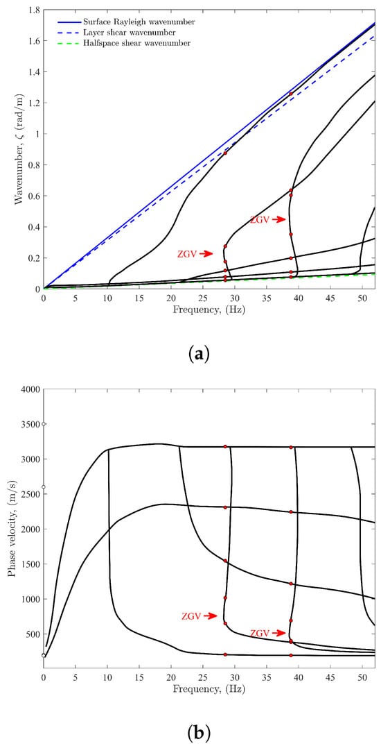
Figure 4.
Dispersion curves of the present method for ground profile, Table 2 in [6], where → indicates a ZGV (zero group velocity) location and the circles  indicate frequencies (28.5 Hz and 38.8 Hz) and wavenumbers where modal shapes are displayed for each (see Figure 5). (a) Propagating wavenumber plotted against frequency for ground profile, Table 2. Zero group velocity detected at 28.4 Hz and 38.7 Hz; (b) Phase velocity plotted against frequency for ground profile, Table 2. Zero group velocity detected at 28.4 Hz and 38.7 Hz.
 indicate frequencies (28.5 Hz and 38.8 Hz) and wavenumbers where modal shapes are displayed for each (see Figure 5). (a) Propagating wavenumber plotted against frequency for ground profile, Table 2. Zero group velocity detected at 28.4 Hz and 38.7 Hz; (b) Phase velocity plotted against frequency for ground profile, Table 2. Zero group velocity detected at 28.4 Hz and 38.7 Hz.
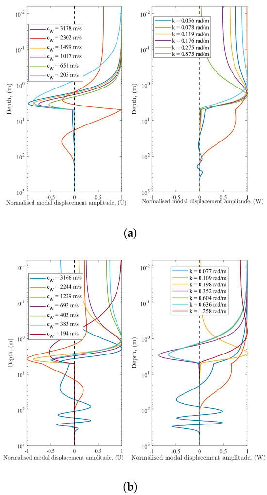
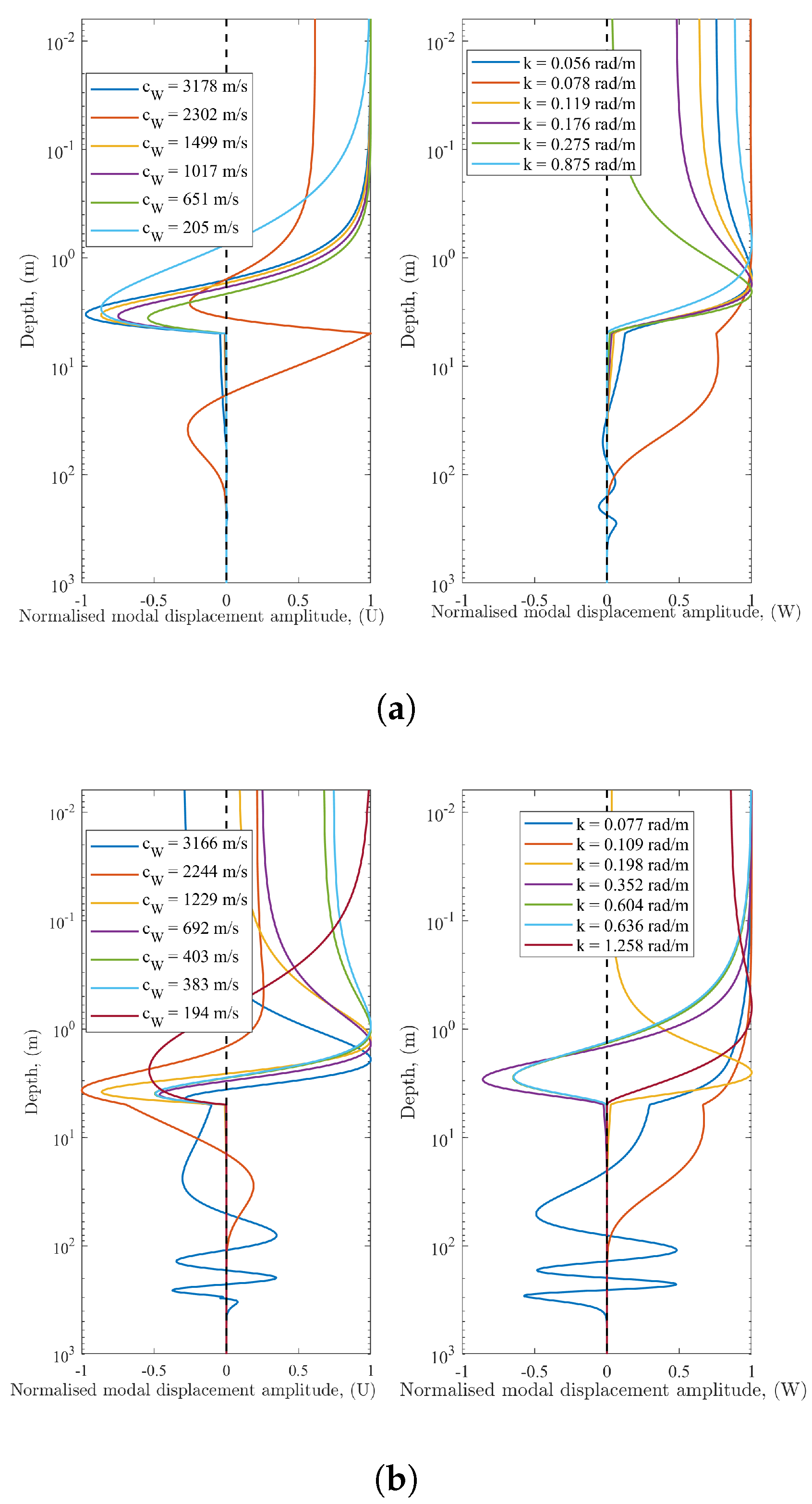
Figure 5.
Modal shapes evaluated at two frequencies related to the Latur earthquake ground profile, Table 2. All modes were evaluated at (a) Six mode shapes plotted against depth on a logarithmic scale at frequency f = 28.5 Hz (see Figure 4), (b) Six mode shapes plotted against depth on a logarithmic scale at frequency, f = 38.8 Hz (see Figure 4).
Figure 4.
Dispersion curves of the present method for ground profile, Table 2 in [6], where → indicates a ZGV (zero group velocity) location and the circles  indicate frequencies (28.5 Hz and 38.8 Hz) and wavenumbers where modal shapes are displayed for each (see Figure 5). (a) Propagating wavenumber plotted against frequency for ground profile, Table 2. Zero group velocity detected at 28.4 Hz and 38.7 Hz; (b) Phase velocity plotted against frequency for ground profile, Table 2. Zero group velocity detected at 28.4 Hz and 38.7 Hz.
 indicate frequencies (28.5 Hz and 38.8 Hz) and wavenumbers where modal shapes are displayed for each (see Figure 5). (a) Propagating wavenumber plotted against frequency for ground profile, Table 2. Zero group velocity detected at 28.4 Hz and 38.7 Hz; (b) Phase velocity plotted against frequency for ground profile, Table 2. Zero group velocity detected at 28.4 Hz and 38.7 Hz.
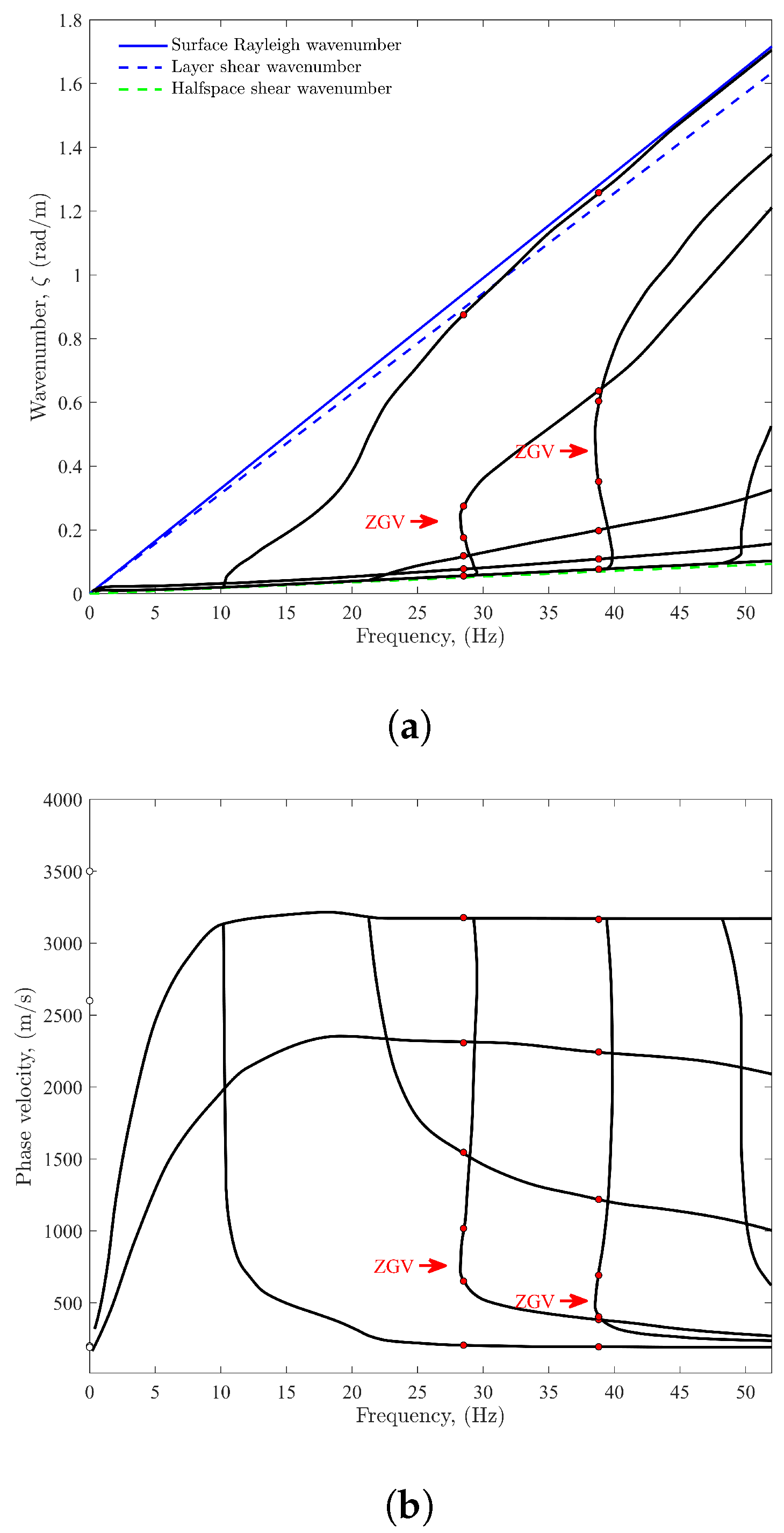
It is well known in the non-destructive inspection community that Lamb modes can possess backward-wave phenomena for certain values of Poisson’s ratio or combinations of layer and substrate. A backward-wave mode is indicated by a typical bend of the dispersion curve, with a negative slope resulting in the negative group velocity of the corresponding guided wave. At the minimum frequency of the backward-wave range, the group velocity becomes zero while the wavenumber remains non-zero; the corresponding wave is referred to as a ZGV mode, which occurs twice in the frequency range used here (Figure 4a). Aside from the opposite phase movement, for which detection is a rather challenging task, the backward wave is considered to manifest itself by a surface-displacement resonance at the ZGV frequency. The red dots in Figure 4b depict the positions at which the propagation modes are computed in the next section. Note well that employing the path continuation algorithm described in Section 2.5 requires an ad hoc adaptive technique that can reduce the step size sufficiently while finding distinct wavenumber solutions.
3.2. Modal Evaluation, Latur Earthquake: Example 2
Figure 5 shows the variation of amplitude (to within an arbitrary amplitude factor) of the vertical and horizontal motion components of the first few modes, plotted against depth up to 1000 m into the ground at frequencies in the vicinity of the appearance of the zero group velocity (ZGV) mode. The depth scale is logarithmic, which highlights the modal behavior nearer the surface. The legends in this figure show the phase velocity and the wavenumber related to individual mode shapes. In Figure 5a, the variation of the radial mode (U) with depth, adjacent to the first ZGV frequency Hz, shifts from maximum to minimum within the top 5 m layer then attenuates quickly to zero through the lower strata in the ground. At the surface, it appears that each modal wavetype can equally contribute to a surface-vibration response, except at the second mode m/s, rad/m, where it appears, on the contrary, that this second mode dominates in carrying the vertical surface wave energy for vertical mode shapes (W). At this frequency, mode shapes in the vicinity of the ZGV turning point are not remarkably different to other modes corresponding to other waves. At the second ZGV turning point, the mode shapes were evaluated at an adjacent frequency, Hz (Figure 5b). Contributors to potential surface waves are evenly distributed through the lowest phase velocity modes across all seven mode shapes displayed here. Interestingly, the mode that relates to the half-space shear wave dispersion curve shows a potential significant contribution in the lower depths of the strata, up to around 600 m below the surface.
3.3. Forced Vibration–Frequency Domain, Latur Earthquake, Example 2
For this section, the results displayed in Figure 6 were obtained with the proposed solution strategy determined by the axisymmetric model, Section 2.3, and are compared with those obtained with a methodology proposed by Wang, [6], a method which has been adopted widely by many researchers in the ground vibration and seismic scientific communities. This approach evolved from the Thomson-Haskell layer transition matrix methods, with an orthonormalization procedure to overcome numerical stability issues with the original propagation algorithm.
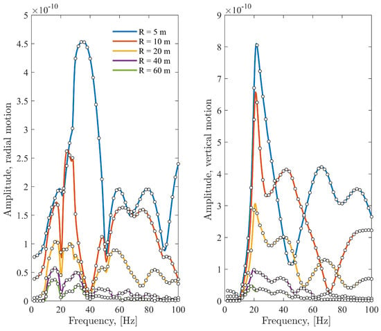
Figure 6.
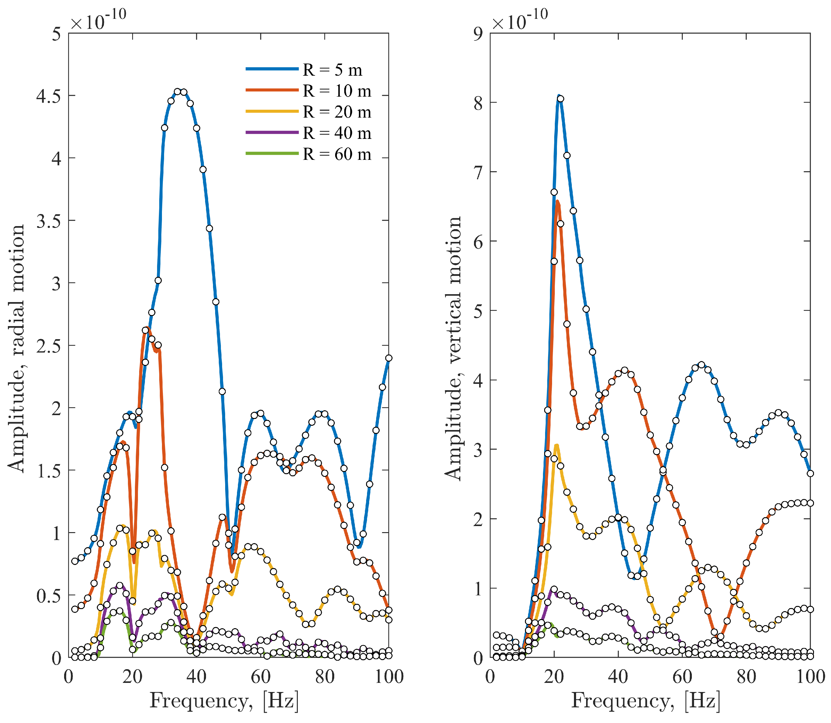
Radial and vertical displacement amplitude at five receiver positions, , and 60 m from center of disk-load. Ground profile represented in Table 2.
In the following, responses to a harmonic surface load were calculated using the hysteretic damping values established in Wang [6]. To conduct this, a circular uniform traction load with radius m, Equation (8), was applied on the surface of a layered soil deposit. The deposit consisted of an m soft soil layer on top of a 300 m deep stiffer layer which overlaid a homogeneous half-space. The soil layer properties are shown in Table 2. Figure 6 shows the vertical and horizontal displacement magnitude at five response points located on the soil surface at distances m from the disk center, as obtained with the proposed solution strategy. Attenuation of radial and vertical displacement with distance is evident throughout the frequency range. At 10 m and beyond it is clear that the greatest response featured close to frequencies 18 and 38 Hz for radial components and 20 and 40 Hz for vertical components beyond 10 m. Although this is not strong evidence of resonance due to the existence of a ZGV mode, an increased amplitude was observed and verified the conclusions by Wang [6].
3.4. Forced Vibration–Time Domain, Latur Earthquake, Example 2
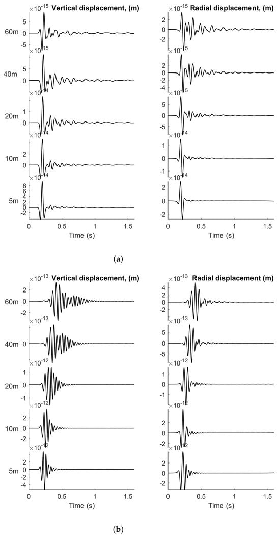
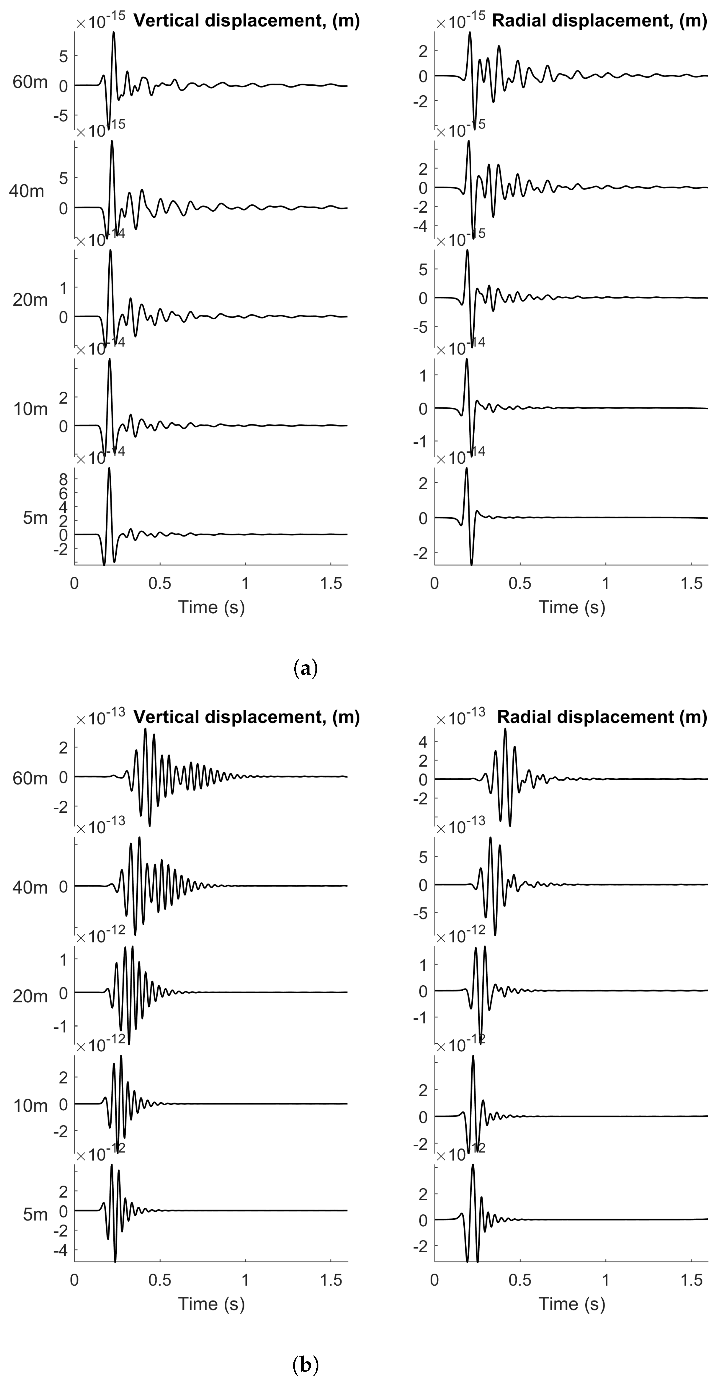
To study the behavior of a time-dependent force located on the surface of the layered half-space we used the numerical fast Fourier transform (FFT) to convert solutions from the frequency domain to the time domain. This technique gives the displacements in the space-time domain, taking a source whose temporal variation is provided by a Ricker wavelet, as defined below. To reduce the computational time we used quadrature in space to calculate responses at a few selected receiver points. Also, since the Ricker wavelet decays rapidly, in both time and frequency, this allowed a computed time domain solution to be calculated in a reasonable time for interpretation.
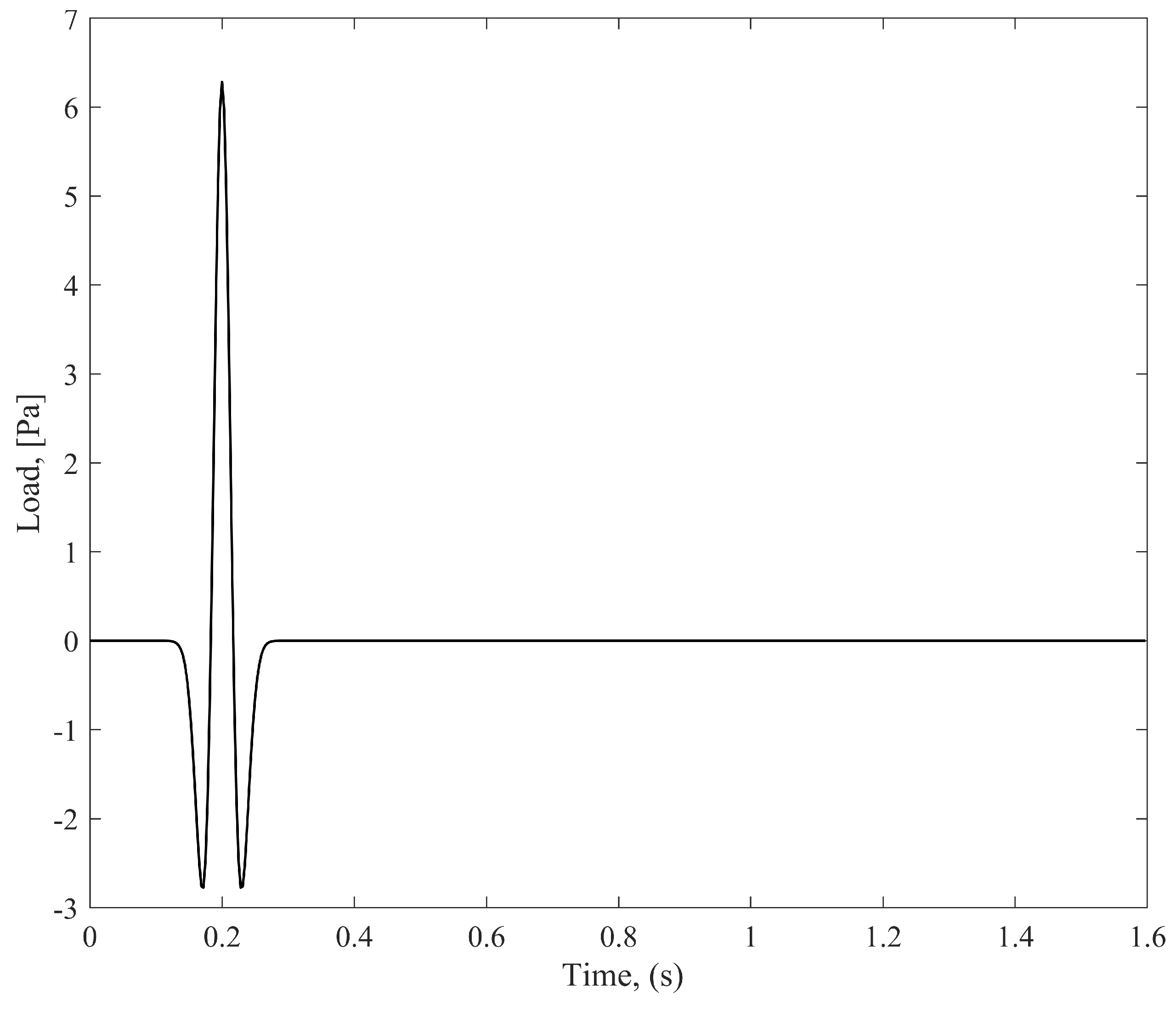
The Ricker wavelet function is given by
where is the amplitude, ; is the time delay at which maximum occurs, and is related to the “natural frequency” of the Ricker wavelet, (see Figure 7). In our calculations we chose the width of the input pulse as Hz, somewhat arbitrarily, but to allow at least the cut-on of a few propagating modes. By applying exponential windowing with damping terms equivalent to the frequency domain, time domain responses were calculated using an FFT with 512 frequency steps up to the Nyquist frequency around 250 Hz.
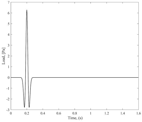
Figure 7.
A Ricker wavelet time profile, which applies to a uniform pressure over a rigid disk in Example 2.
The two sets of results highlight the difference between a model that includes a soft top layer (see Figure 8a) and one which does not (see Figure 8b). Both sets of solutions naturally exhibit a strong dispersive nature as the envelope of the solution wave packet propagates along the surface. This is especially evident for the soft 5 m layer result: there appears a second wave packet in the vertical response at distances that develop from 40 m, which is due to the soft-layer response. As reported in [6], the “slow” speeds of the two wave packets effected by ZGV dispersion are clearly evident.
4. Conclusions
A uniformly applicable model has been developed for studying the propagation of surface vibrations through elastic layers of arbitrary depth. This model comprises an elastic, isotropic, and homogeneous layer overlaying a half-space. A dynamic stiffness matrix, well-conditioned for this model, has been established through the projection of characteristic functions onto depth-dimension endpoints. To explore the behavior of natural propagating modes within these layers under zero-surface-stress conditions, singular values of the dynamic stiffness were computed. The characteristic equation was also employed to determine the solution shapes of these propagating modes. For instance, when examining a ground profile with a high Poisson’s ratio in the top layer over a deep strata, a zero group velocity mode was identified. This mode corresponded to a layer resonance, which had been previously observed. Vibrational responses due to a fixed disk load in the frequency domain indicated resonances at cut-off frequencies. Additionally, time domain results were obtained, confirming the existence of non-dispersive wave packets, as suggested by earlier researchers. This formulation’s broad applicability for dynamic stiffness matrices opens the door to modeling various new problems where plane strain conditions are applicable. Furthermore, it can be readily expanded to account for sub-layers of different materials within the strata and extended to three-dimensional problems, where an exact 6x6 dynamic stiffness matrix could be established.
In summary, the following conclusions have been drawn:
- A well-conditioned dynamic stiffness matrix has been developed for layers of arbitrary depths.
- The characteristic equation has been formulated in a way that requires unknowns to be expressed only at material layer nodal points, eliminating the need for subdividing the strata.
- The model has been applied to known ground profiles, revealing the existence of zero group velocity modes. Examples involving time histories and frequency domain responses have been provided.
- Anisotropic constitutive models, such as transversely isotropic or orthotropic models, may be used to describe the mechanical behavior of anisotropic soils in numerical analyses, and this is an area in which we are interested in extending our knowledge for future research.
- The appearance of zero group velocity modes may be studied efficiently in a sensitivity analysis, since the size of the problem is small and the continuation methodology can aid in testing its existence.
- Future advancements towards a 3D dynamic stiffness matrix, involving the analytical determination of 36 entries, could significantly reduce computational costs in full-sized models well within reach on small desktop PCs.
Author Contributions
Conceptualization, A.T.P.; methodology, A.T.P. and B.L.; validation, A.T.P.; formal analysis, A.T.P.; investigation, A.T.P. and B.L.; resources, B.L.; writing—original draft preparation, A.T.P.; writing—review and editing, A.T.P. and B.L. All authors have read and agreed to the published version of the manuscript.
Funding
This research received partial funding by the Ministry of Science and Technology (MOST) of China: Advanced computational methods for vibro-acoustic couplings in complex structures 2023-01-01 2024-12-31 G2023025006L.
Data Availability Statement
Data available on request.
Acknowledgments
The first author gratefully acknowledges the Division of Acoustics and Structural Mechanics, Department of Construction Sciences, Lund University, Sweden.
Conflicts of Interest
The authors declare no conflicts of interest. The funders had no role in the design of the study; in the collection, analyses, or interpretation of data; in the writing of the manuscript; or in the decision to publish the results.
Appendix A
For each layer, the displacement field can be obtained from potentials as
where and are the solutions of two dimensional wave equations for each elastic layer:
For the sake of argument, we assume a single layer has depth and that the z-coordinate for the layer is locally specified, . In this region, the corresponding stress fields are subsequently obtained as
The pair of Equations (A2) are transformed into the Fourier domain, with respect to x, via the transform pair
For the sake of completeness, the Fourier transform pair in the case of radial symmetry is
This introduces the Fourier component k, which is also commonly known as the wavenumber in the horizontal direction. Upon the transformation, we obtain differential equations in the z-direction, which now includes frequency and the wavenumber k as parameters. Much of the analysis of this problem is identical to the solution of similar problems [15,24], where a dynamic stiffness matrix is derived, such that
where are the transforms of the stress functions, and are the transforms of the displacements. Note that it is common practice to write solutions to the subsequent homogeneous ordinary differential equations in terms of cosh and sinh functions. However, this choice of characteristic functions is not convenient for problems involving a spatial domain of arbitrary size. Hence, the general solutions in the Fourier domain may be written in the scaled formulation, after introducing wavenumber pairs and :
where the branch cuts are chosen so that . The reason for choosing the scaled exponential characteristic functions over hyperbolic functions is clear if you attempt to evaluate and manipulate these functions on a personal computer, as commented on by Kausel in his compendium [16], Basically, this choice of basis ensures that the characteristic functions do not grow unbounded with layer depth, as , which would occur with unscaled elementary functions. Subsequently, it is evident that the displacements also will not grow unbounded with depth. Now, by inserting the scaled ansatz into the Equations (A1), this yields the element displacements on the upper and lower interfaces, respectively, for layer :
where and the complex-valued matrix is given by
To derive a dynamic stiffness matrix for element we need the transformed stress equations, which can be developed by Equation (A3):
where and
with the decaying functions . We are now in a position to combine Equations (A8) and (A10) to obtain at a single matrix formulation that expresses the displacements and stresses at the interfaces. The general dynamic stiffness matrix for any global domain thus becomes a complex valued matrix:
where . The algebraically complicated and non-symmetric matrix is given in Appendix B.
Appendix B
We follow the notation that the element in the row and column is denoted . The matrix is, however, not symmetric, but we have , , , , , , , and . The remaining elements of the matrices are as follows:
Here,
References
- Peplow, A.T. Surface ground vibration from a strip–load acting over elastic layers: A uniform approach. Soil Dyn. Earthq. Eng. 2019, 116, 289–292. [Google Scholar] [CrossRef]
- Pekeris, C. Theory of propagation of explosive sound in shallow water. Geol. Soc. Am. Mem. 1948, 27. [Google Scholar] [CrossRef]
- Kausel, E.; Roesset, J. Stiffness matrices for layered soils. Bull. Seismol. Soc. Am. 1981, 71, 1743–1761. [Google Scholar] [CrossRef]
- Thomson, W. Transmission of elastic waves through a stratified solid medium. J. Appl. Phys. 1950, 21, 89–93. [Google Scholar] [CrossRef]
- Haskell, N. The dispersion of surface waves on multilayered media. Bull. Seismol. Soc. Am. 1953, 43, 17–34. [Google Scholar] [CrossRef]
- Wang, R. A simple orthonormalization method for stable and efficient computation of Green’s functions. Bull. Seismol. Soc. Am. 1999, 89, 733–741. [Google Scholar] [CrossRef]
- Rokhlin, S.; Wang, L. Stable recursive algorithm for elastic wave propagation in layered anisotropic media: Stiffness matrix method. J. Acoust. Soc. Am. 2002, 112, 822–834. [Google Scholar] [CrossRef] [PubMed]
- Dunkin, J.W. Computation of modal solutions in layered, elastic media at high frequencies. Bull. Seismol. Soc. Am. 1965, 55, 335–358. [Google Scholar] [CrossRef]
- Kausel, E. Generalized stiffness matrix method for layered soils. Soil Dyn. Earthq. Eng. 2018, 115, 663–672. [Google Scholar] [CrossRef]
- Tan, E.L. Stiffness matrix method with improved efficiency for elastic wave propagation in layered anisotropic media. J. Acoust. Soc. Am. 2005, 118, 3400–3403. [Google Scholar] [CrossRef]
- Tan, E.L. Hybrid compliance-stiffness matrix method for stable analysis of elastic wave propagation in multilayered anisotropic media. Acoust. Soc. Am. J. 2006, 119, 45. [Google Scholar] [CrossRef] [PubMed]
- Ba, Z.; Wu, M.; Liang, J.; Zhao, J.; Lee, V.W. A two-step approach combining FK with SE for simulating ground motion due to point dislocation sources. Soil Dyn. Earthq. Eng. 2022, 157, 107224. [Google Scholar] [CrossRef]
- Huang, M.; Cegla, F.; Lan, B. Stiffness matrix method for modelling wave propagation in arbitrary multilayers. Int. J. Eng. Sci. 2023, 190, 103888. [Google Scholar] [CrossRef]
- Ewing, W. Elastic Waves in Layered Media; McGraw-Hill: New York, NY, USA, 1957. [Google Scholar]
- Jones, D.; Petyt, M. Ground vibration in the vicinity of a strip load: A two-dimensional half-space model. J. Sound Vib. 1991, 147, 155–166. [Google Scholar] [CrossRef]
- Kausel, E. Fundamental Solutions in Elastodynamics: A Compendium; Cambridge University Press: Cambridge, UK, 2006. [Google Scholar] [CrossRef]
- Karasalo, I. Exact Finite Elements for Wave Propagation in Range-Independent Fluid-Solid Media. J. Sound Vib. 1994, 172, 671–688. [Google Scholar] [CrossRef]
- Verruijt, A. An Introduction to Soil Dynamics; Springer: Dordrecht, The Netherlands, 2010. [Google Scholar] [CrossRef]
- Jones, D.; Petyt, M. Ground vibration in the vicinity of a strip load: An elastic layer on an elastic half-space. J. Sound Vib. 1993, 161, 1–18. [Google Scholar] [CrossRef]
- Ivansson, S.; Karasalo, I. A high-order adaptive integration method for wave propagation in range-independent fluid–solid media. J. Acoust. Soc. Am. 1992, 92, 1569–1577. [Google Scholar] [CrossRef]
- Lamb, H. On Group-Velocity. Proc. Lond. Math. Soc. 1904, s2-1, 473–479. [Google Scholar] [CrossRef]
- Strobbia, C. Surface Wave Methods: Acquisition, Processing and Inversion. Ph.D. Thesis, Dottorato di Ricerca in Geoingegneria Ambientale, Politecnico di Torino, Turin, Italy, 2003. [Google Scholar]
- Kumar, J.; Naskar, T. A fast and accurate method to compute dispersion spectra for layered media using a modified Kausel-Roësset stiffness matrix approach. Soil Dyn. Earthq. Eng. 2017, 92, 176–182. [Google Scholar] [CrossRef]
- Jones, D.; Petyt, M. Ground vibration in the vicinity of a strip load: An elastic layer on a rigid foundation. J. Sound Vib. 1992, 152, 501–515. [Google Scholar] [CrossRef]
Disclaimer/Publisher’s Note: The statements, opinions and data contained in all publications are solely those of the individual author(s) and contributor(s) and not of MDPI and/or the editor(s). MDPI and/or the editor(s) disclaim responsibility for any injury to people or property resulting from any ideas, methods, instructions or products referred to in the content. |
© 2024 by the authors. Licensee MDPI, Basel, Switzerland. This article is an open access article distributed under the terms and conditions of the Creative Commons Attribution (CC BY) license (https://creativecommons.org/licenses/by/4.0/).

