1. Introduction
The rapid global deployment of fifth-generation mobile networks (5G) [
1] is enabling a broad range of new application scenarios, including virtual and augmented reality, massive Internet-of-Things deployments, and high-definition media streaming. These applications place stringent demands on the 5G core network for higher throughput, lower latency, and greater operational flexibility. Within this context, 5G Wireless and Wired Network Convergence (5G-WWC) [
2,
3] have emerged as a pivotal architectural development.
5G-WWC objectives, target services, and beneficiaries. The primary goal of 5G-WWC is to allow wireline subscribers—residential and enterprise customers connected via fibre, DSL, or cable through a Fixed Network–Residential Gateway (FN-RG)—to access 5G core services over their existing wired infrastructure without requiring 5G-capable radio equipment. The services made available to these wireline users are those managed by the 5G core: unified policy and charging, per-session QoS enforcement, and seamless session continuity as devices transition between wired and wireless access. It is important to note that network slicing is a capability of the 5G core network as a whole; the 5G-WWC architecture allows wireline-attached devices to consume network slices already provisioned by the core, but slicing is not a function provided independently by the AGF or UPF. Similarly, Fixed Wireless Access (FWA)—where a radio link replaces the last-mile cable—is a distinct deployment model that does not involve a wireline AGF; the AGF is specifically designed to bring wired-access subscribers into the 5G core ecosystem. From an operator’s perspective, consolidating wired and mobile subscribers onto a single 5G core eliminates the cost of running parallel fixed-broadband and mobile cores, and enables converged services such as unified QoS, consistent charging, and coordinated mobility management from a single management plane.
Table 1 summarises the relevant 5G core functions, the assumed wireline (AGF/UPF) functions in a 5G-WWC deployment, and the services that the proposed Combined AGF/UPF framework supports or can optionally support.
Wireline access, however, imposes a distinctive performance challenge: fibre-based aggregation networks routinely carry traffic at 10–100 Gbps per aggregation point, far exceeding the per-user throughput typical of radio access. The user-plane functions at the wireline entry point into the 5G core—in particular, the AGF and the UPF—must therefore sustain near-line-rate throughput while simultaneously enforcing per-session QoS policies and GTP-U tunnelling. This combination quickly saturates purely software-based implementations.
5G-WWC addresses this by integrating wired access into the 5G architecture through a shared core network, reducing operational costs and enabling seamless handover between wired and wireless connectivity. To support this integration, the Third Generation Partnership Project (3GPP) [
4] and the Broadband Forum (BBF) [
5] have defined a set of new network functions, of which the Wireline Access Gateway Function (AGF) [
6] acts as the wired-access entry point. The AGF provides Ethernet connectivity, relays control messages and user data to the 5G core, and proxies 5G-core connections on behalf of legacy wired devices—bridging the conventional fixed network and the 5G core.
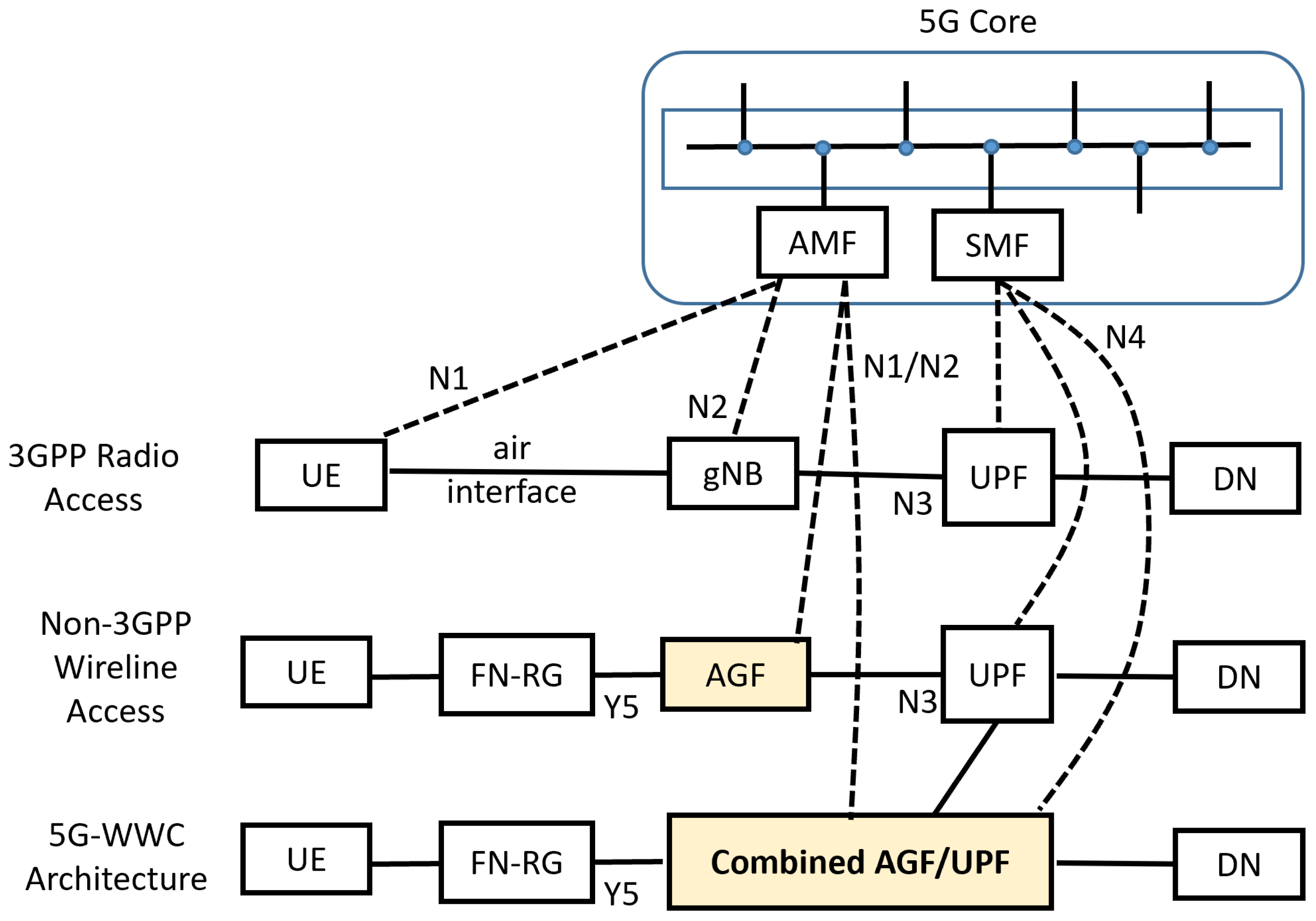
With the AGF in place, the 5G network supports three paths for User Equipment (UE) to reach a Data Network (DN), as illustrated in
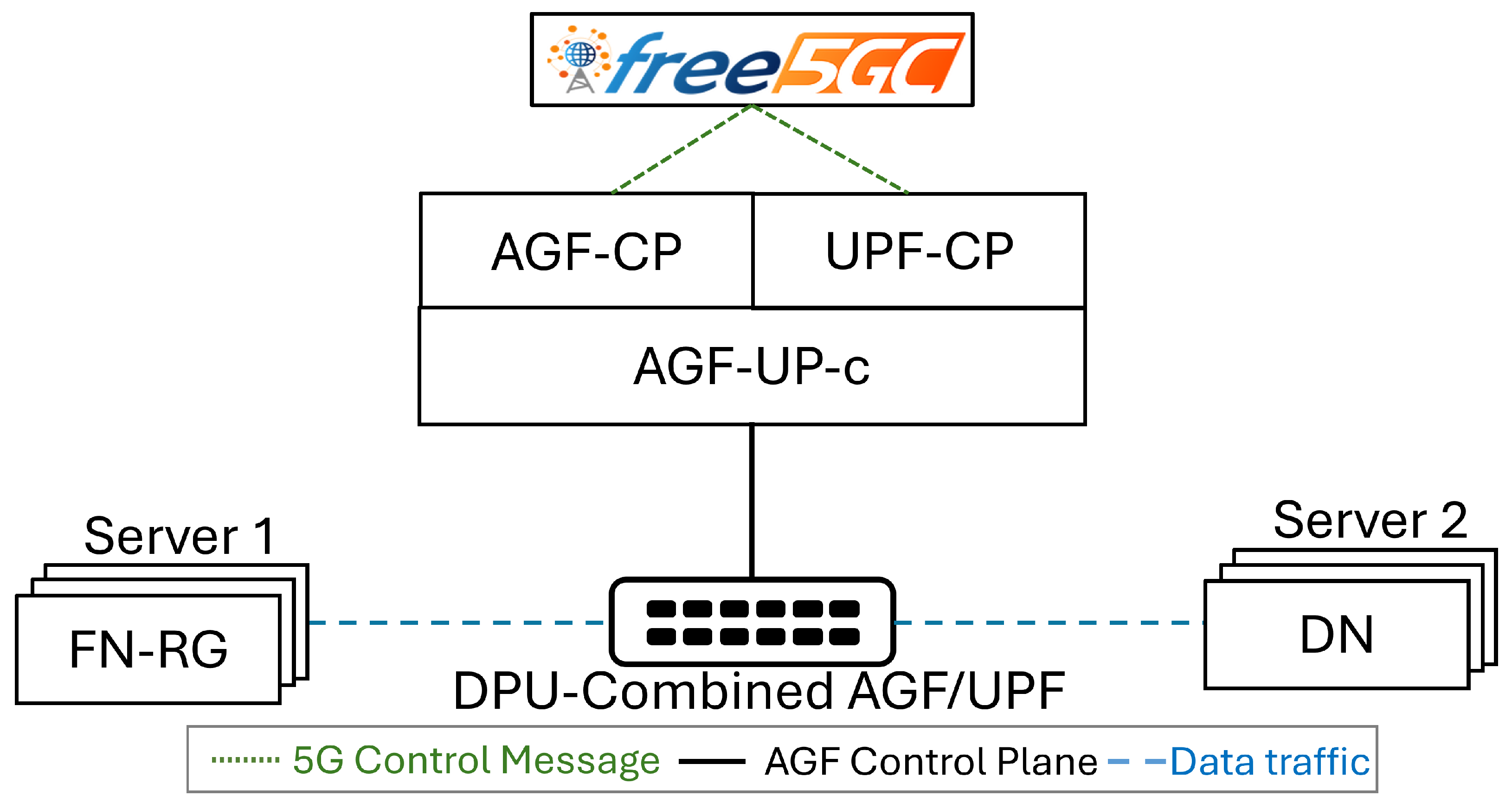
Figure 1. A 5G-capable UE connects via a gNB (gNodeB) and the UPF in the 5G core. A non-5G-capable UE connects through a separate AGF and UPF. The separation of AGF and UPF in the second path, however, increases network complexity, raises deployment costs, reduces efficiency, and introduces additional security exposure. The third path—the 5G-WWC architecture—therefore unifies AGF and UPF into a single Combined AGF/UPF function, reducing the number of deployed network elements, simplifying management, and improving both performance and security. In this configuration, the combined function may connect the UE directly to a DN or to a further UPF.
Research context and motivation. This work is carried out at a university research group with an established track record of collaboration with network operators and equipment vendors in the 5G networking domain. The test platform was constructed using commercially available NVIDIA BlueField-2 DPUs and commodity servers, reflecting hardware configurations already adopted in production data-centre and telco edge deployments. The immediate goal of this work is to provide an open, standards-compliant reference implementation of the 5G-WWC user plane that (i) demonstrates the technical feasibility of near-line-rate AGF/UPF convergence on programmable hardware for wireline broadband subscribers, (ii) exposes the design principles—hardware abstraction, configurable pipelines, Generic Flow Rules—needed for industrial adoption, and (iii) serves as a foundation for follow-on work targeting full TR-456/TR-470 compliance, N9 interface support, SmartNIC/FPGA portability, and integration with security mechanisms such as flow-rule authentication and control-plane access control. Industrial adoption of the proposed system requires that the abstraction layer introduces negligible control-path overhead: as detailed in
Section 3, the Generic Flow Rule translation is a lightweight, one-time per-session operation executed entirely in software at session setup, so it does not lie in the data-plane forwarding path and does not affect per-packet latency or throughput.
Our prior work [
7] followed the Control and User Plane Separation (CUPS) principle, dividing AGF into the AGF Control Plane (AGF-CP) and the AGF User Plane (AGF-UP), and restructured AGF-UP using P4 switches with an abstraction layer between AGF-UP-c and AGF-UP-u to support multiple user plane implementations. However, that design did not fully comply with CUPS principles: several AGF-CP responsibilities (e.g., PDU Session processing) were misplaced in AGF-UP-c, reducing the flexibility of AGF-CP access. Furthermore, ref. [
7] did not address the integration of AGF with UPF or the Combined AGF/UPF scenario required by the 5G-WWC standard. An acceleration framework for the 5G UPF using P4 switches was proposed in [
8], which demonstrated the feasibility of programmable data plane acceleration for the 5G user plane, but equally did not address heterogeneous AGF/UPF integration.
This paper makes the following contributions beyond our prior work:
Reconstructed CUPS Architecture. We redesign the AGF architecture to fully comply with CUPS principles, moving all 5G-related control processing (including PDU Session management) exclusively to AGF-CP, and introducing a clean User Plane Abstraction Layer between AGF-CP and AGF-UP.
Generic Flow Rule Interface and Hardware Abstraction Mechanism. We define a Generic Flow Rule as the unit of communication between the control plane and the User Plane Abstraction Layer. An adapter-based design allows the same control plane to manage heterogeneous user plane implementations (DPU, P4 switch) without modification.
Configurable AGF/UPF Integration Framework. We extend the architecture to support separated AGF + UPF and Combined AGF/UPF deployments through a unified configurable framework, where AGF-CP and UPF-CP operate independently while sharing a common abstraction layer.
Optimised Combined AGF/UPF Pipeline. We propose a merged DPU-based pipeline for Combined AGF/UPF that eliminates redundant GTP-U encapsulation/decapsulation steps present in a naive cascaded design, reducing latency and improving packet-processing throughput.
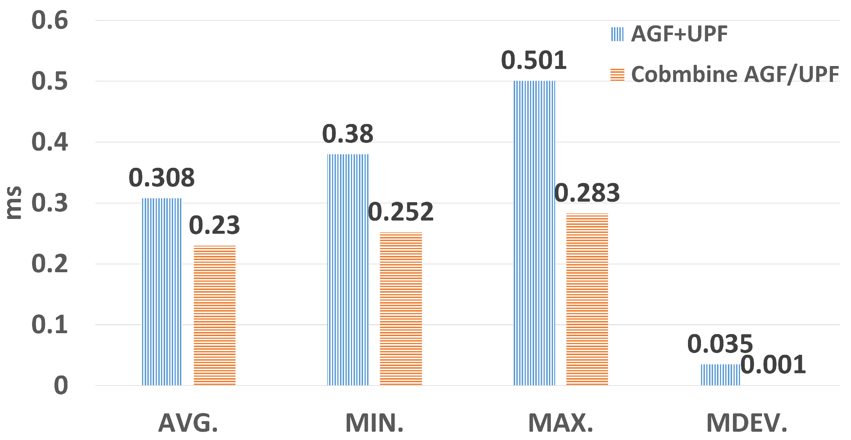
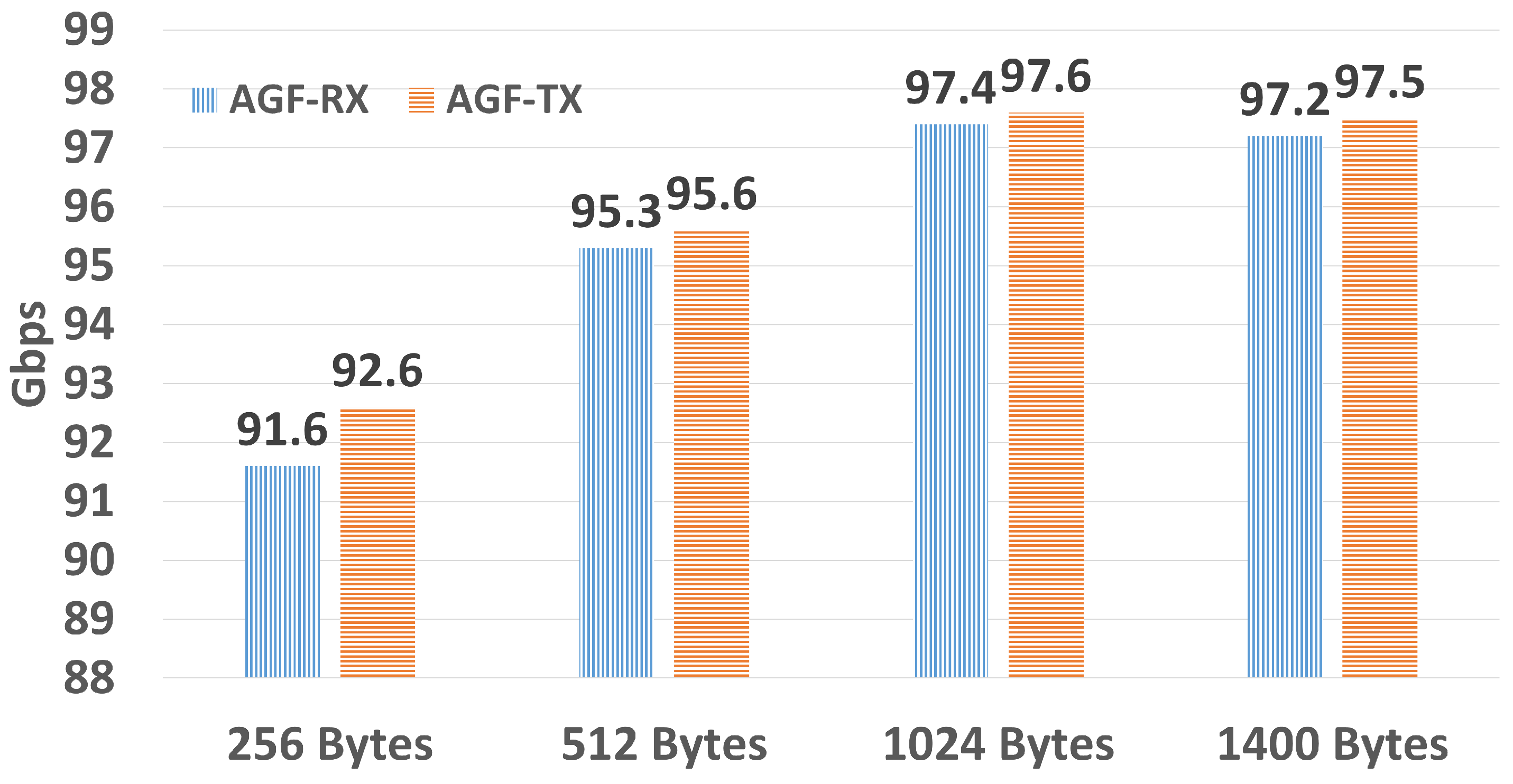
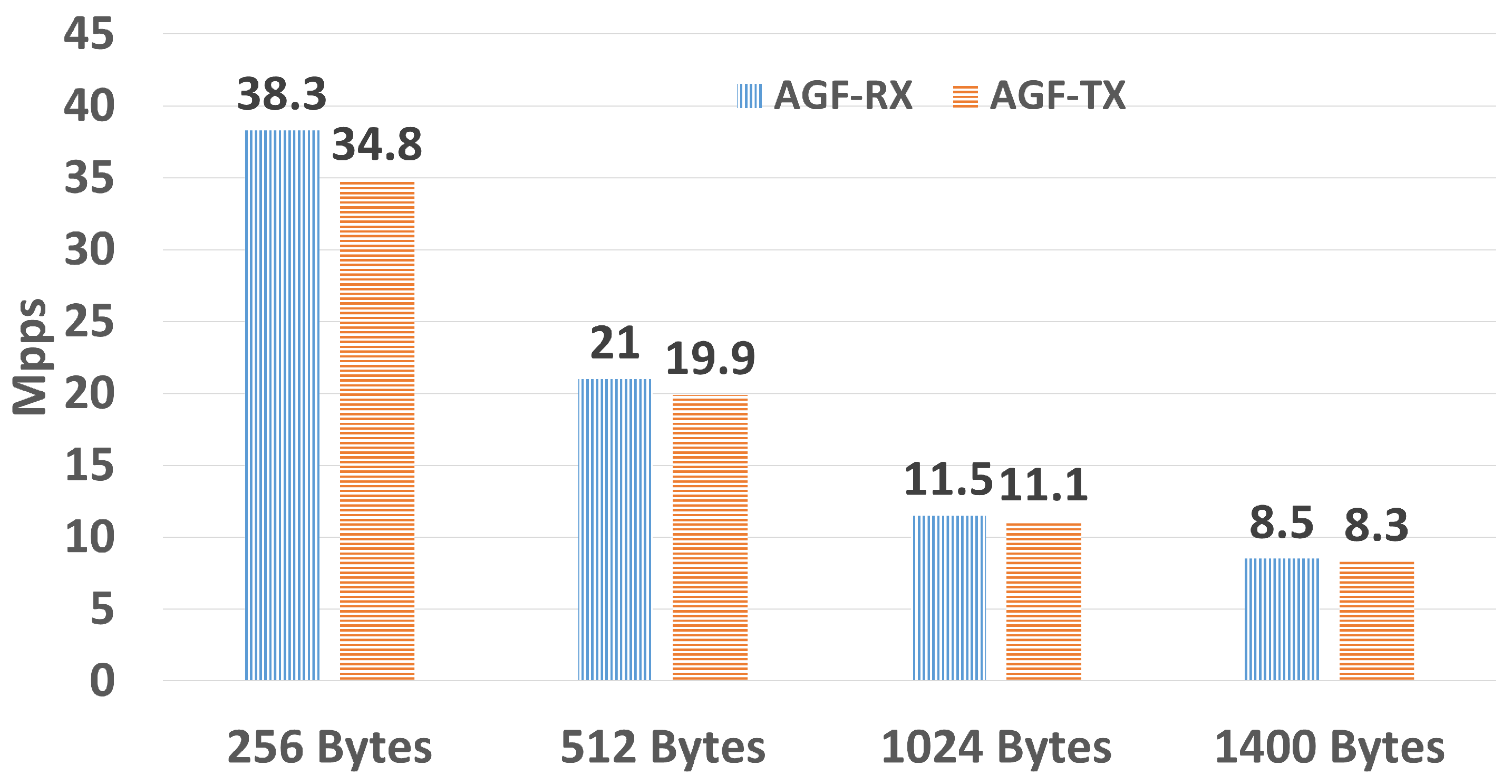
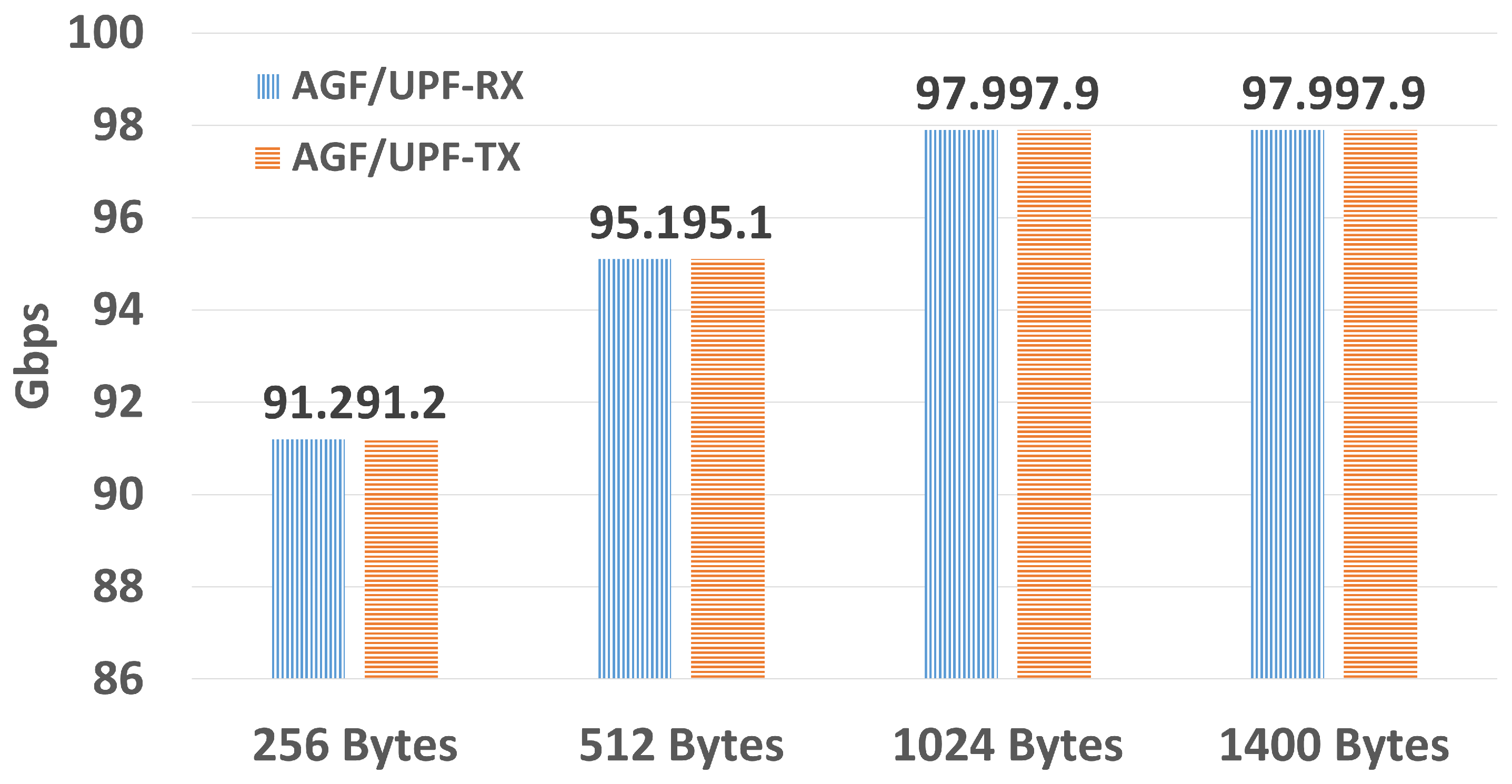
Experimental Validation. We demonstrate near-100 Gbps throughput on NVIDIA BlueField-2 DPUs across all three TR-470 scenarios, and show that the Combined AGF/UPF configuration achieves lower latency than the separated AGF + UPF configuration, along with DPU resource utilisation measurements.
The remainder of this paper is organised as follows.
Section 2 reviews related work.
Section 3 describes the reconstructed CUPS architecture for AGF.
Section 4 details the DPU-based AGF-UP implementation.
Section 5 presents the configurable AGF/UPF integration framework.
Section 6 reports experimental results, and
Section 7 concludes the paper.
2. Related Work
Intel’s AGF architecture adheres to the BBF and 3GPP Fixed-Mobile Convergence (FMC) standards [
9], supporting fixed, fixed-wireless, and hybrid access to enable seamless 5G-broadband integration and edge-service delivery. Its adoption of CUPS decouples the control and user planes for independent, scalable evolution. The AGF user plane is built on the optimised Vector Packet Processing (VPP) framework with the Data Plane Development Kit (DPDK), achieving high-speed I/O performance. A key limitation is its dependence on Intel-specific hardware (e.g., the E810 Ethernet controller), which constrains cross-platform portability and raises the risk of technology lock-in.
Wang et al. [
8] accelerated 5G UPF forwarding and enforced UPF quality-of-service using P4 switches in an SDN-based setup, where ONOS mediates between the UPF and the SMF by translating SMF messages into P4 table entries. The present paper reuses the UPF control-plane implementation, incorporating its PFCP Agent as the UPF-CP component in our Combined AGF/UPF framework.
Jin et al. [
7] accelerated the AGF user plane with P4 switches and proposed an SDN-based adaptive AGF management architecture with an abstraction layer that separates and integrates user-plane behaviours for multi-user-plane access. However, that design did not strictly follow the CUPS principle: several 5G control-plane components (e.g., PDU Session processing) were misplaced in the AGF user-plane controller, forcing the user plane to perform control-plane tasks and reducing AGF-CP flexibility. The present work references the ONOS module from that earlier design for control-plane management, corrects its architectural shortcomings, and introduces a cleaner, fully CUPS-compliant architecture.
Several open-source 5G core implementations—including free5GC [
10] and Open5GS—offer software-based UPFs that serve as performance baselines. These software UPFs typically achieve only a few Gbps on commodity hardware, constrained by kernel networking overhead. Hardware-accelerated approaches using P4 switches or DPUs can approach line-rate performance. The key challenge that distinguishes the present work from both software-based and prior hardware-accelerated solutions is supporting
heterogeneous deployments: simultaneously managing AGF, UPF, and Combined AGF/UPF across different hardware platforms through a single, unified configurable control plane. No prior work has addressed this three-way integration requirement within a single framework.
3. CUPS Architecture for AGF
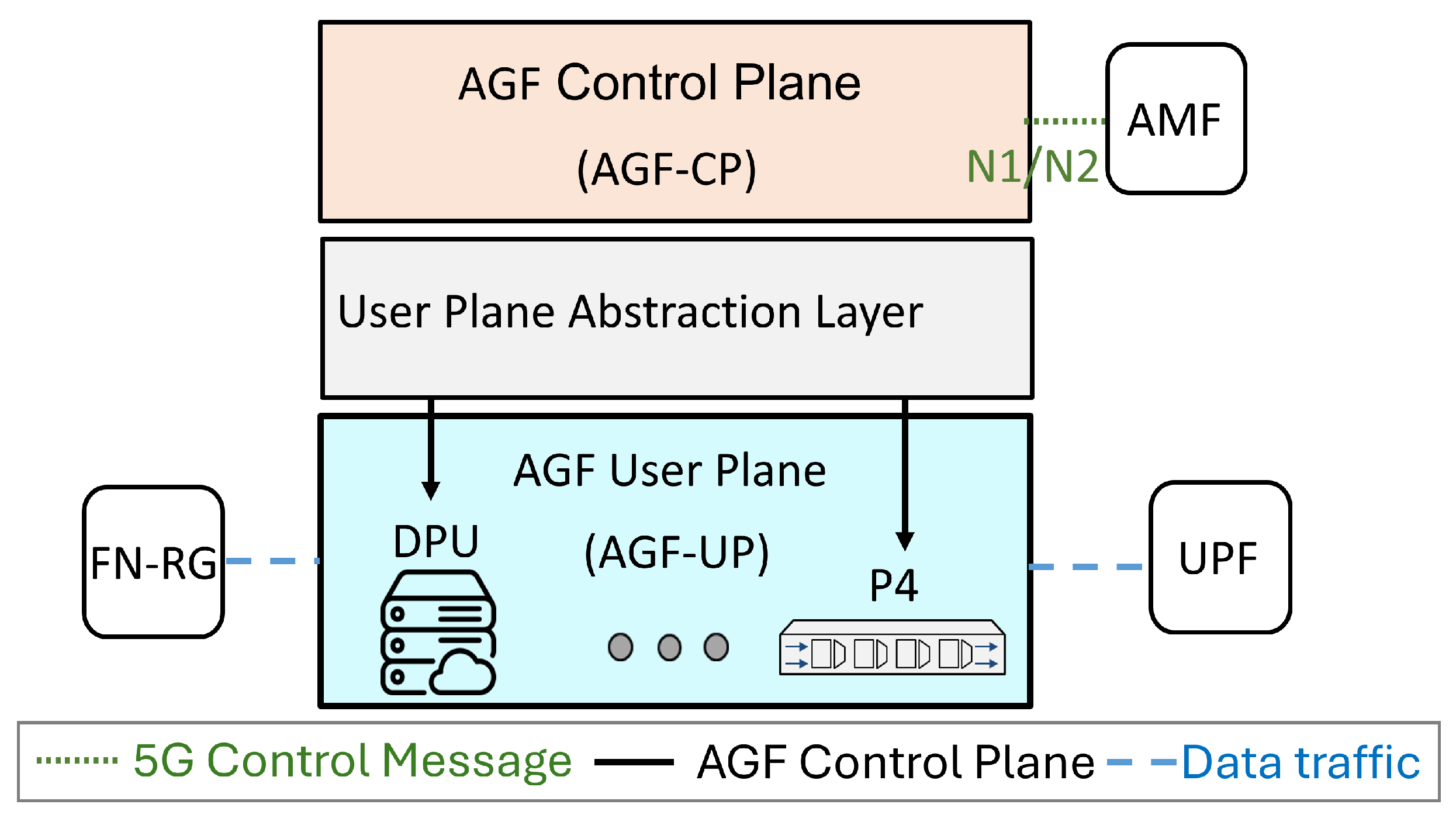
Our AGF architecture consists of three components—AGF-CP, a User Plane Abstraction Layer, and AGF-UP—as shown in
Figure 2. AGF-CP handles all 5G-related signalling and PDU session management, and coordinates the integration of wired network functions. AGF-UP performs data-plane packet processing: encapsulation, decapsulation, forwarding, and per-flow QoS enforcement to allocate bandwidth across sessions. Either a DPU or a P4 switch may be used to implement AGF-UP.
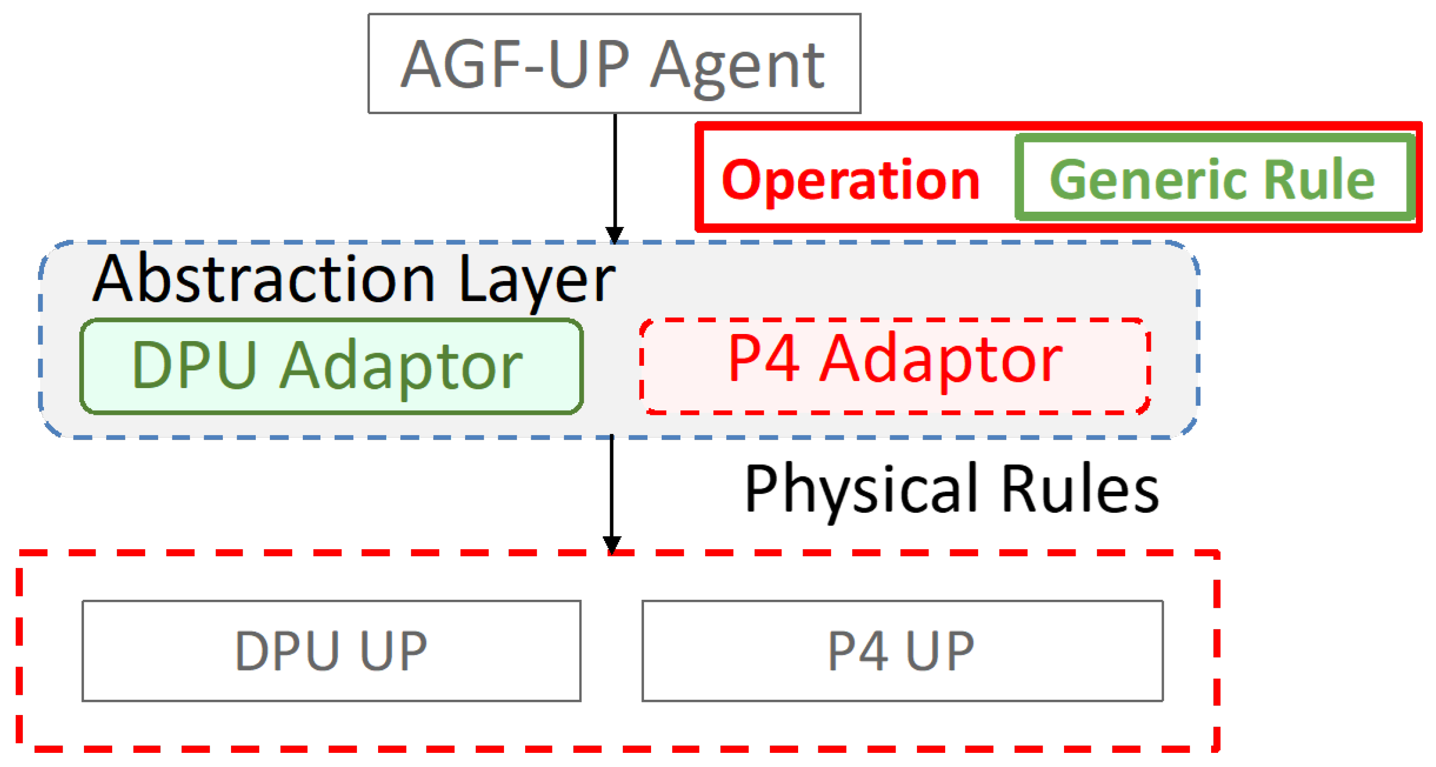
The User Plane Abstraction Layer provides a universal interface to the control plane, allowing the control plane to issue Generic Flow Rules without knowledge of the underlying user plane details. Each Generic Flow Rule is an implementation-agnostic tuple containing the following fields:
PDI (Packet Detection Information): UE IP address, TEID (for downlink traffic), and traffic direction (uplink/downlink).
FAR ID: An abstract forwarding-action identifier specifying drop, forward, or buffer actions, along with next-hop information.
QER ID: A quality-of-service rule identifier carrying Guaranteed Bit Rate (GBR) and Maximum Bit Rate (MBR) parameters.
Rule Operation: Install, modify, or delete.
Upon receiving a Generic Flow Rule from the AGF-UP Agent (or from the PFCP Agent in the UPF-CP case), the Abstraction Layer selects the appropriate Adapter based on the administrator-configured device type (DPU or P4) and function type (AGF, UPF, or Combined AGF/UPF). The selected Adapter translates the Generic Flow Rule into target-specific physical rules.
Table 2 summarises this translation for the DPU and P4 targets.
Since the abstraction layer handles all format conversion, user-plane implementations require no knowledge of upper-layer control details. New AGF-UP backends—whether DPU- or P4-based—can be integrated simply by writing a corresponding adapter, without any changes to the control plane or to other adapters.
4. DPU Approach: BlueField-2
To demonstrate the flexibility of the proposed architecture, this section describes a DPU-based AGF-UP implementation. For AGF-CP, we built on the ONOS module from [
7] for control-plane management, reused the AGF-UP-c module for P4-based AGF from [
7], and added an AGF-UP Agent to handle PDU Sessions. For AGF-UP, we used the NVIDIA BlueField-2 DPU [
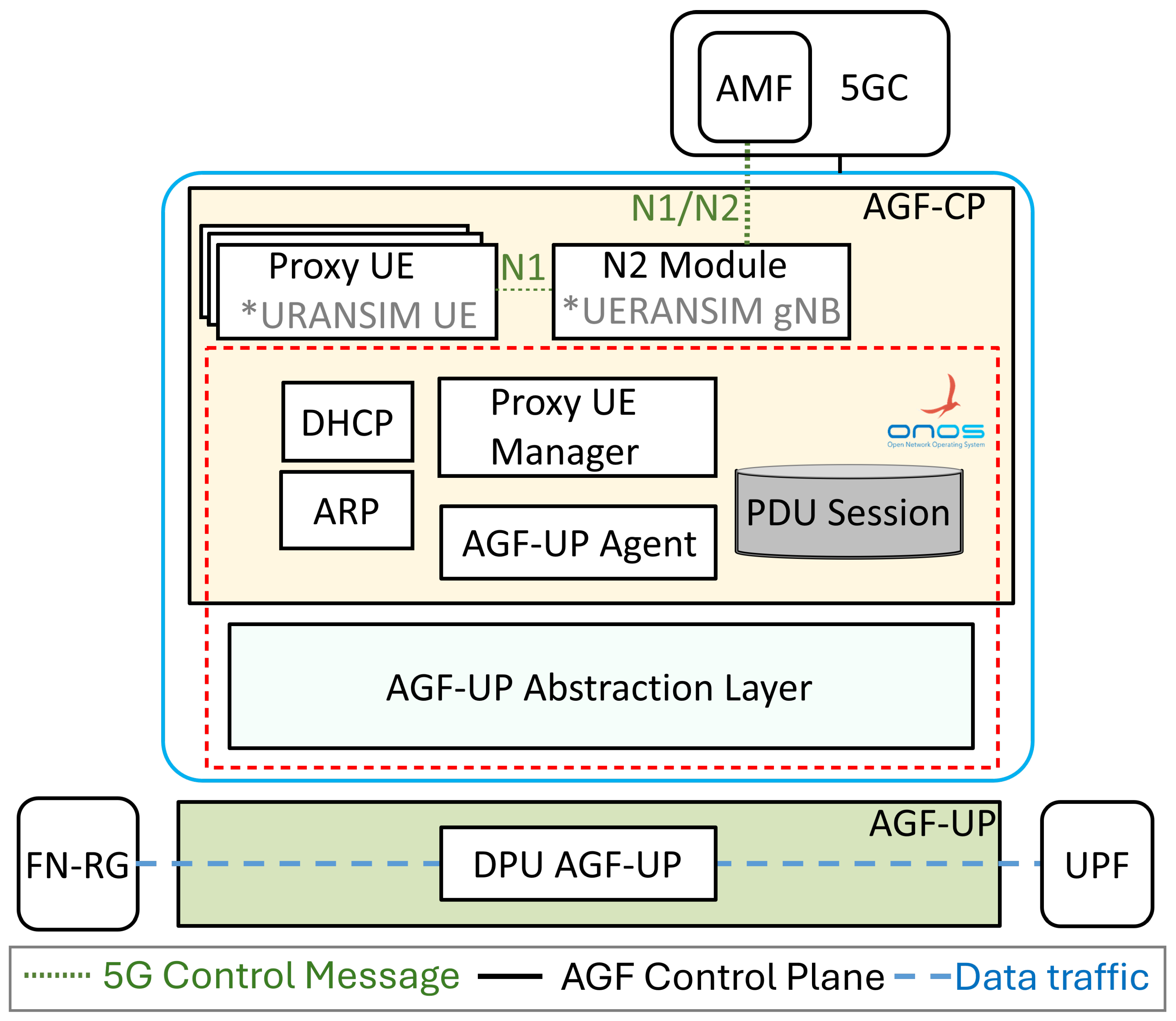
11], running a DOCA application over a hardware-accelerated DPU pipeline. For the User Plane Abstraction Layer, we developed an ONOS-based application that exposes a universal user-plane interface. The complete architecture is shown in
Figure 3.
4.1. Implementation of AGF-CP
We designed a Proxy UE by modifying the UE Simulator in UERANSIM to replace the FN-RG for the UE registration process. We removed the USER module related to the user plane of the original UE Simulator since we use the DPU for user-plane acceleration.
For the N2 Module, we modified the gNB Simulator in UERANSIM to pass the IP and PDU Session information obtained from the Proxy UE to the Proxy UE Manager. The gNB Simulator and the Proxy UE Manager communicate using UDP sockets.
The Proxy UE Manager is an ONOS module for managing Proxy UE instances and storing PDU Session information. When detecting a new FN-RG connection request, it creates a new Proxy UE instance to assist the UE in registration. After registration, this module receives and stores the PDU Session information from the N2 Module in the PDU Session Store.
The DHCP Module handles DHCP messages from FN-RG and notifies the Proxy UE Manager upon receiving a DHCP Discover message. The ARP Module handles ARP packets from FN-RG and UPF.
The AGF-UP Agent runs as an ONOS application and acts as the user-plane abstraction client. It generates implementation-agnostic Generic Flow Rules from UE PDU Session information and forwards them to the User Plane Abstraction Layer. When the Proxy UE Manager signals that 5G UE registration is complete, the AGF-UP Agent retrieves the updated session data, constructs new data-flow rules in the generic format, and submits them to the abstraction layer via ONOS inter-application calls.
4.2. Implementation of AGF-UP
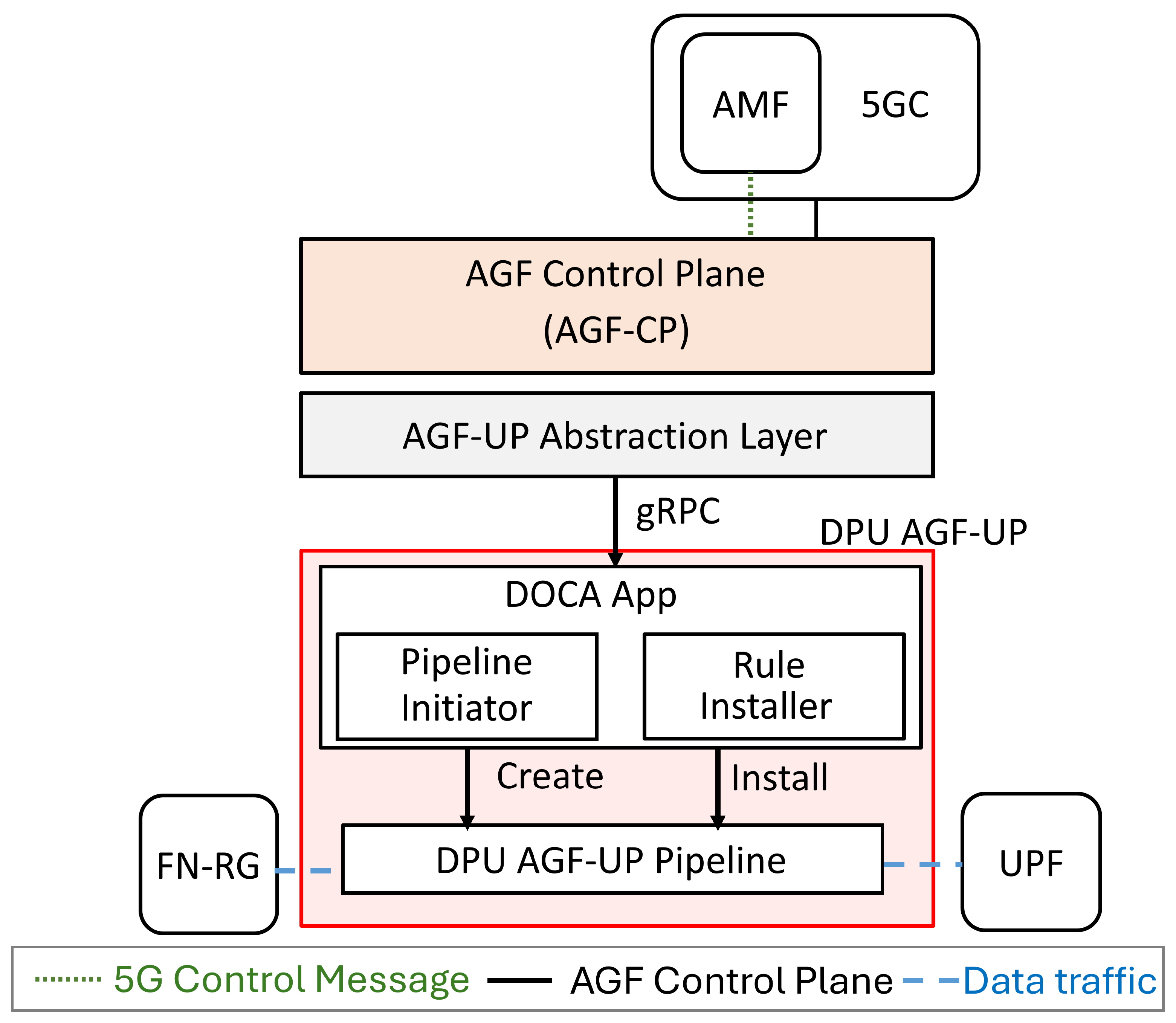
As shown in
Figure 4, the DOCA App in AGF-UP is responsible for initialising and overseeing the AGF-UP pipeline and facilitating communication with the DPU Adapter. It consists of two principal functions. The
Pipeline Installer instantiates the AGF-UP pipeline, whose specifications are predefined during the compilation phase, upon executing the DOCA application. The
Rule Installer receives rules from the DPU Adapter through the gRPC protocol and installs them into the AGF-UP pipeline, enabling dynamic adaptation and enforcement of network policies. The DPU Pipeline is physically deployed on the DPU ASIC and is responsible for processing and forwarding packets according to the configured rules.
4.2.1. AGF Uplink Pipeline
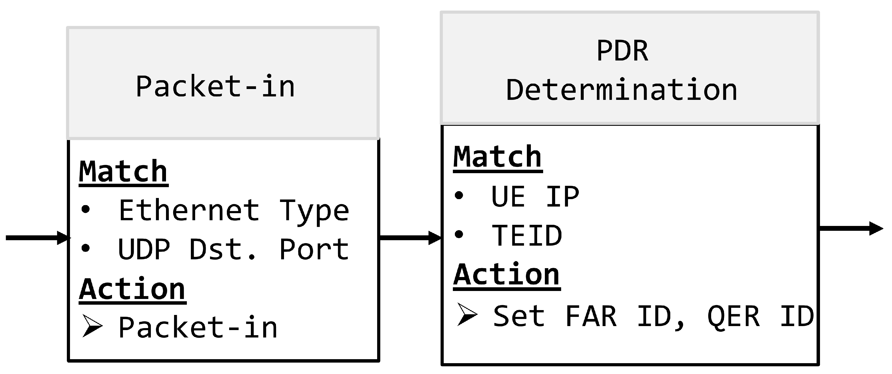
Figure 5 shows the AGF uplink pipeline. The Packet-in table parses incoming packets by Ethernet Type and UDP Port to identify control plane packets and initiate packet-in actions. The PDR Determination table then matches AGF traffic by UE IP for the uplink pipeline and assigns FAR ID and QER ID for subsequent table matching.
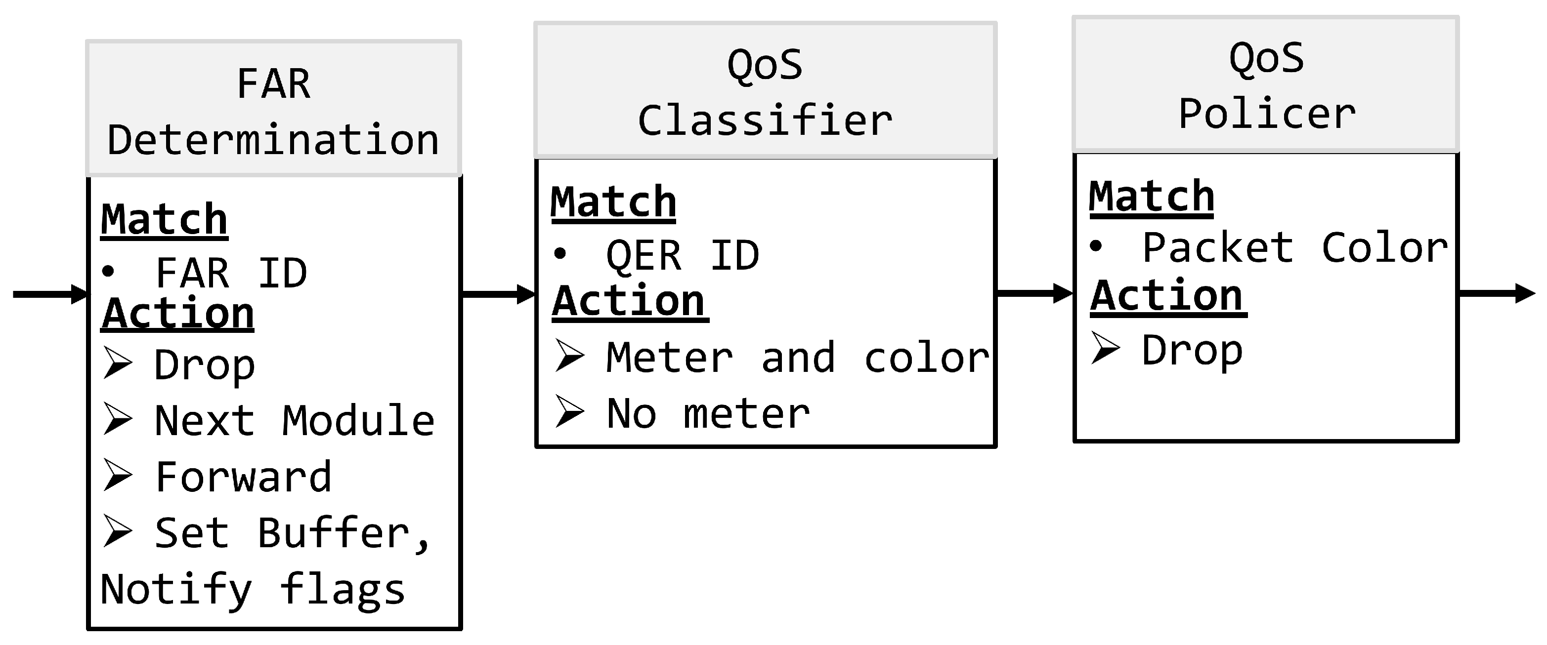
Figure 6 shows the tables related to FAR and QER. The FAR table matches the FAR ID distributed from PDR to perform corresponding actions. The QER table matches the QER ID to implement the corresponding QoS policy.
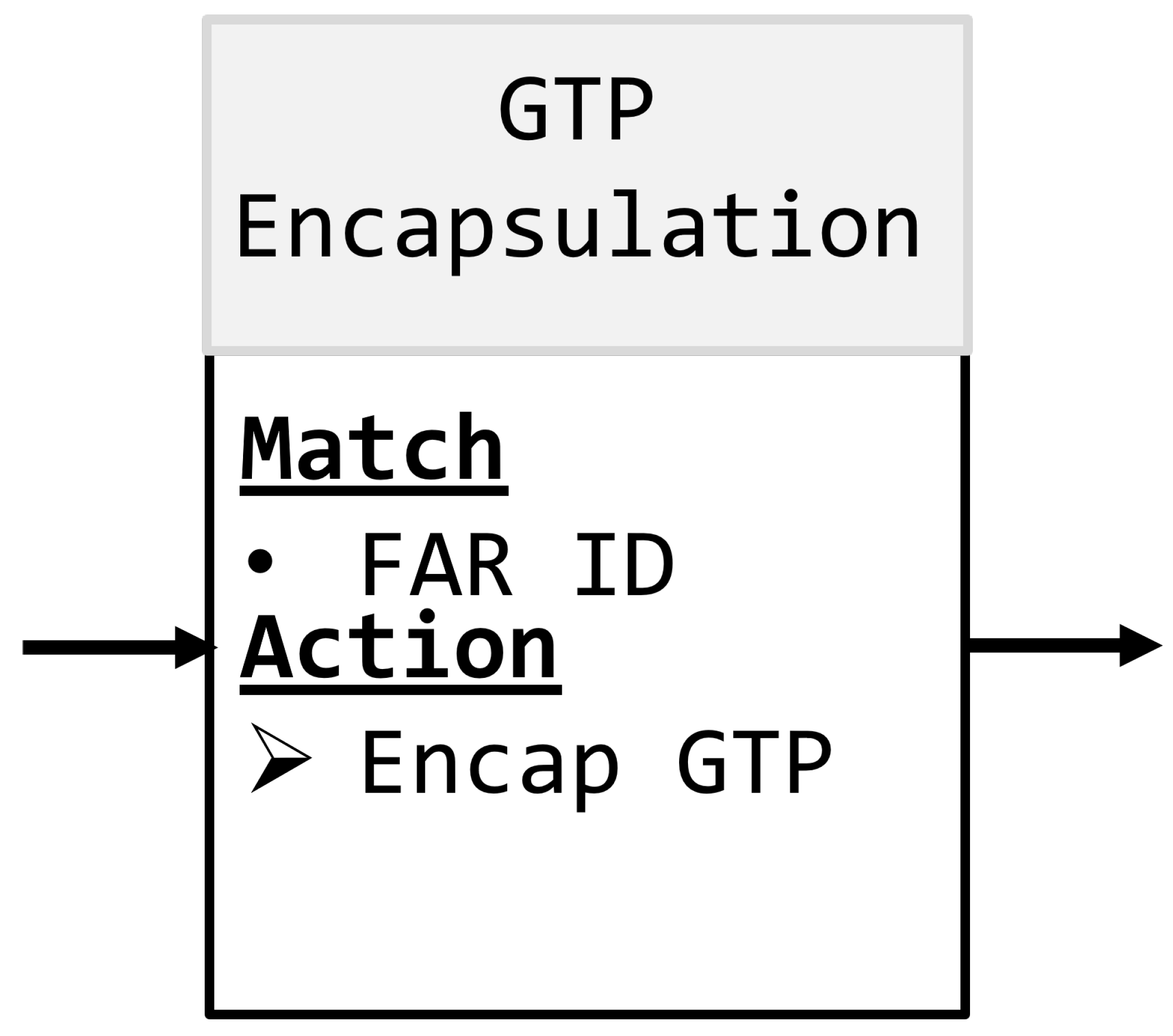
GTP-U header encapsulation is necessary following the QER stage in the uplink pipeline. As shown in
Figure 7, the GTP Encapsulation table checks the FAR ID to decide whether to carry out the GTP-U header encapsulation.
4.2.2. AGF Downlink Pipeline
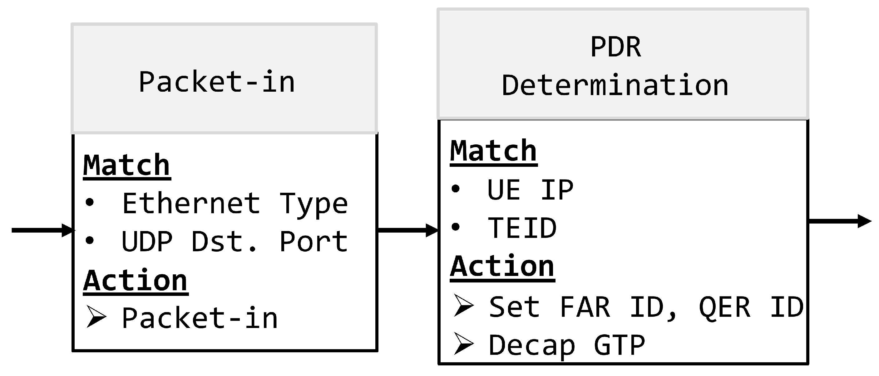
Figure 8 depicts the PDR for the downlink AGF. The key difference from the uplink pipeline is that after matching the UE IP and TEID, the PDR performs GTP-U header decapsulation. Regarding the FAR and QER sections, the downlink pipeline is similar to the uplink one. In the downlink pipeline, packets can be sent to FN-RG without GTP-U header encapsulation.
4.3. User Plane Abstraction Layer
The User Plane Abstraction Layer is implemented as an ONOS application, illustrated in
Figure 9. Its purpose is to provide a universal user-plane interface that allows different hardware backends to be interconnected without changes to the control plane. At onboarding time, the administrator specifies the device type and function type; the abstraction layer selects the matching adapter accordingly. Each adapter translates incoming Generic Flow Rules into the target-specific physical rules for its hardware, as detailed in
Table 2.
5. Configurable AGF/UPF Integration Framework
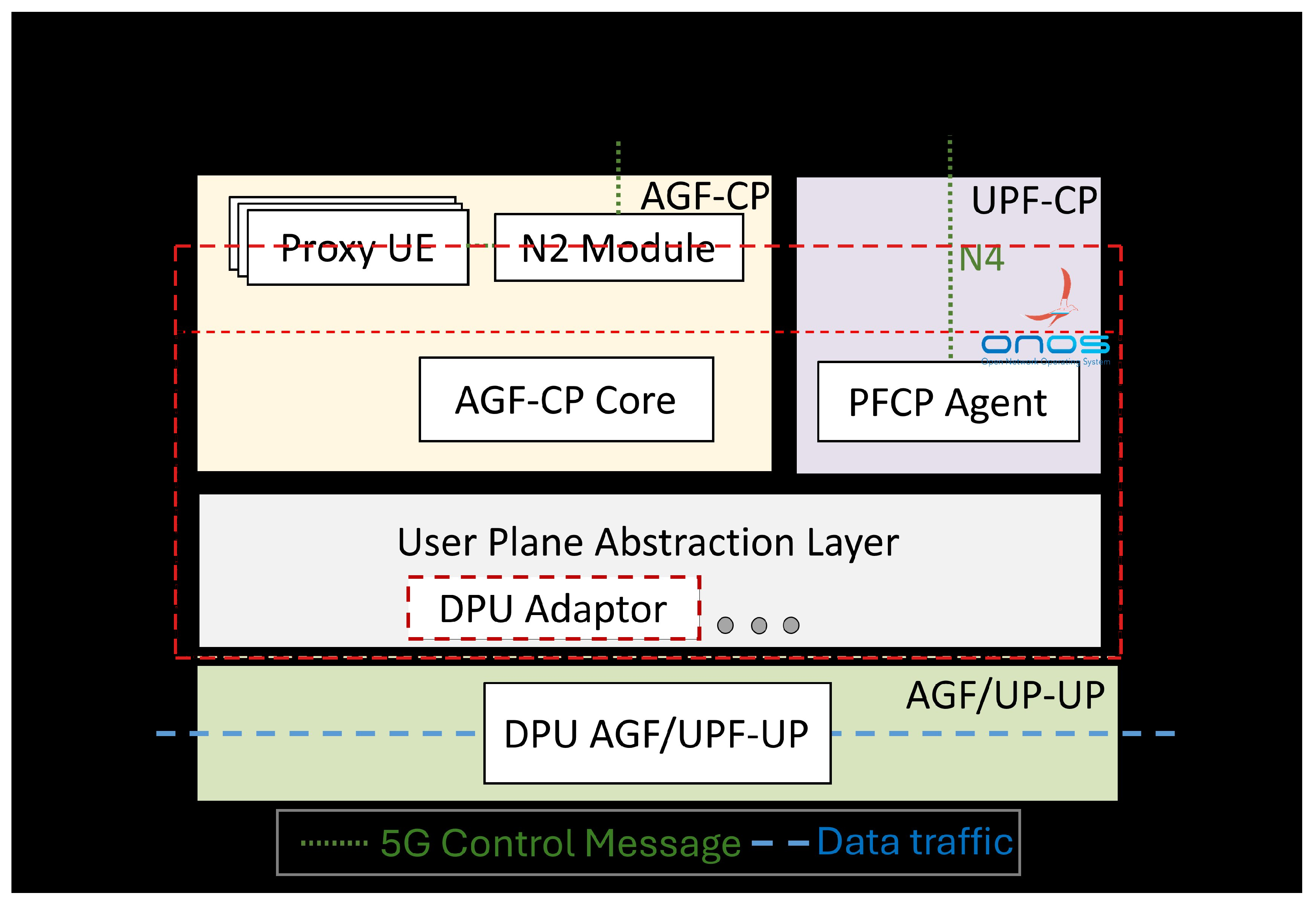
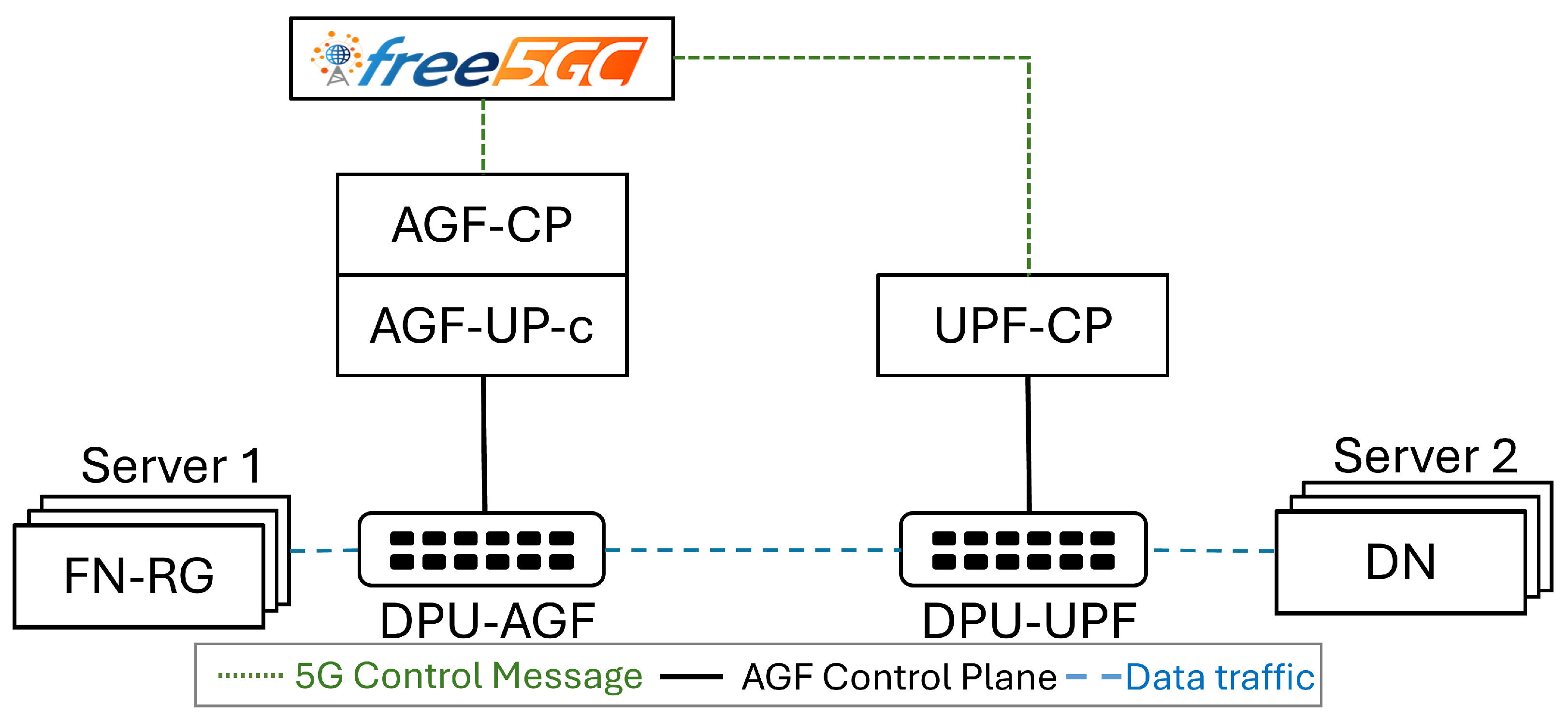
The control plane supports both separated and combined AGF/UPF deployments. To keep control-plane changes minimal and maximise flexibility, AGF-CP and UPF-CP run independently, each managing only its own domain: AGF-CP for AGF-related tasks in AGF-only and Combined AGF/UPF modes, and UPF-CP for UPF-related tasks. A merging function in the Abstraction Layer receives rules from both control planes, combines them where necessary, and dispatches the resulting physical rules to the hardware. The full platform, therefore, comprises four components—AGF-CP, UPF-CP, the User Plane Abstraction Layer, and AGF/UPF-UP—as shown in
Figure 10.
UPF-CP handles PFCP messages arriving on the N4 interface through its PFCP Agent module, translates them into Generic Flow Rules, and forwards the rules to the user plane via the abstract interface.
On the user-plane side, a single unified configurable Abstraction Layer serves all deployment modes. It extends the per-function abstraction of
Section 3 by additionally exposing an interface to the PFCP Agent in UPF-CP, and by providing adapters for UPF-only, AGF-only, and Combined AGF/UPF configurations. For the Combined AGF/UPF mode, the DPU pipeline is further optimised by merging the AGF and UPF forwarding tables, eliminating redundant GTP-U encapsulation and decapsulation operations, and thereby increasing throughput and reducing pipeline depth.
7. Conclusions
This paper presented a configurable integration framework for heterogeneous AGF and UPF deployments, using NVIDIA BlueField-2 DPUs to implement the user plane for both AGF-only and Combined AGF/UPF configurations. The framework’s abstraction layer unifies the separated control and user planes: a Generic Flow Rule interface and an adapter-based translation mechanism allow a single control plane to drive heterogeneous hardware backends without modification. The DPU-based user-plane implementation satisfies all three TR-470 scenarios and achieves near-100 Gbps throughput. Resource utilisation measurements confirm that packet processing is offloaded almost entirely to the DPU ASIC, keeping ARM core CPU overhead minimal and validating the efficiency of the hardware-offloading approach.
Several directions for future work remain. First, the Combined AGF/UPF should support N9 interface processing for inter-UPF forwarding as required by TR-456; adding N9 is expected to introduce a further GTP-U tunnel between UPFs and modest additional table entries without fundamentally changing the pipeline structure. Second, scalability under large numbers of simultaneously active sessions and high-frequency mobility events—including rapid session creation and handover—warrants dedicated study; the DPU ASIC hardware pipeline is inherently parallel, but the control-plane session-setup rate and table management under churn remain open research questions. Third, security hardening of the control plane is an important direction: mechanisms to authenticate Generic Flow Rules, prevent malicious flow-rule injection, and enforce access control policies at the AGF/UPF boundary should be integrated into the framework. Fourth, small-packet throughput optimisations—hardware-level packet coalescing at the DPU ingress port and batched flow-rule installation—represent a promising path to full line-rate performance across all payload sizes. Fifth, extending the adapter library to support SmartNIC and FPGA-based user planes would further validate the generality of the proposed abstraction mechanism and reduce the risk of hardware vendor lock-in.