Article

Analysis and Design of a Brushless WRSM with Harmonic Excitation Based on Electromagnetic Induction Power Transfer Optimization

1
Department of Mechanical Engineering, Ghulam Ishaq Khan Institute, Swabi 23640, Pakistan
2
Department of Electrical Engineering, National University of Computer and Emerging Sciences, Islamabad 44000, Pakistan
3
Department of Electrical Engineering, Incheon National University, Incheon 22012, Republic of Korea
4
Department of Electrical Engineering Technology, Benazir Bhutto Shaheed University of Technology and Skill Development, Khairpur Mirs 66020, Pakistan
5
Department of Electrical and Engineering, Inha University, Incheon 22212, Republic of Korea
6
Department of Electrical Engineering, Sukkur IBA University, Sukkur 65200, Pakistan
*
Authors to whom correspondence should be addressed.
Magnetism 2025, 5(4), 26; https://doi.org/10.3390/magnetism5040026
Submission received: 29 August 2025 / Revised: 29 September 2025 / Accepted: 14 October 2025 / Published: 18 October 2025

Abstract

This paper proposes a method to analyze the effect of the rotor’s harmonic winding design and the output of a brushless wound rotor synchronous machine (WRSM) for optimal excitation power transfer. In particular, the machine analyzed by the finite-element method was a 48-slot eight-pole 2D model. The subharmonic magnetomotive force was additionally created in the air gap flux, which induces voltage in the harmonic winding of the rotor. This voltage is rectified and fed to the field winding through a full bridge rectifier. Eventually, a direct current (DC) flows to the field winding, removing the need for external excitation through brushes and sliprings. The effect of the number of harmonic winding turns is analyzed and the field winding turns were varied with respect to the available rotor slot space. Optimization of the harmonic excitation part of the machine will maximize the rotor excitation for regulation purposes and optimize the torque production at the same time. Two-dimensional finite-element analysis has been performed in ANSYS Maxwell 19 to obtain the basic results for the design of the machine.

1. Introduction

Ever since the advent of high-energy permanent magnet (PM) materials, research on PM machines has attracted significant consideration and attention, which has continued to the present day. Some of the recent advancements have been in exploiting the power density limits of interior permanent magnet synchronous machines (IPMSMs) [1,2]. Specifically, the wide-speed range operation of PM Vernier machines has been specifically investigated for use in electric vehicles and other variable-speed applications [3,4]. However, the applicable machine structure along with the drive system becomes costly, mainly due to the use of PM in applications where the product cost is a main consideration [5,6,7]. The high-energy rare-earth materials to be used in manufacturing PMs have their own issues to be solved, ranging from trade disputes to end-use recycling [8,9]. In a parallel world, a new issue has emerged: whether the rare-earth PM motors will be removed from electric vehicles (EVs), and what type of motors can be used in place of them [7,10]. In recent years, wound rotor synchronous machines (WRSMs) have been investigated as an alternative, owing to the cheaper structure manufacturing and wide-speed range capabilities given the degree of freedom for flux weakening, which is comparable to the PM machines [11,12,13,14,15,16,17,18]. Additionally, a PM-less rotor exhibits no PM loss; the machine features improved safety through direct field control during inverter fault conditions, and there is no problem of demagnetization [19,20,21].
However, WRSM has an inherent problem regarding the assembly of brushes and sliprings. Because of the problem associated with WRSM, comparative investigation always favors the use of a PMSM instead of WRSM in many applications. To address the problems, many brushless excitation techniques have been proposed for WRSMs [22,23,24,25,26,27].
The design of a large synchronous machine incorporates an extended-shaft brushless exciter to control the high power excitation currents [28,29,30,31]. However, on a small scale, this exciter can be integrated into the main machine for compact brushless and/or self-excitation purposes, reducing the cost and volume of the system [32,33].
One solution is generating harmonic flux in the air gap along with the fundamental flux to induce voltage in an additionally provided winding on the rotor, which is connected to the field winding of the rotor through a rectifier for brushless excitation [34,35,36,37]. However, when the higher harmonic flux is injected into the stator windings through modified inverters or pulse width modulation (PWM) techniques, the core losses due to additional high-frequency harmonics need to be considered. Alternatively, special stator winding designs have also been proposed in the literature for generating a subharmonic component of the air gap flux with either single or dual-inverter schemes [38,39,40,41,42,43,44].
Stator winding topology optimization with fractional-slot concentrated windings and alternative coil pitch designs can be used to suppress certain space harmonics by canceling their magnetomotive force (MMF) contributions, thereby reducing associated torque ripples and losses. Alternatively, hybrid design approaches using harmonic windings with carefully chosen pole numbers and placement can further reduce coupling of unwanted harmonics into the rotor.
In ref. [44], two inverters supply current to two three-phase winding sets, each located in half of the stator, to create a subharmonic MMF for brushless operation. The arrangement of stator armature winding with different magnitudes of currents in each set of armature winding creates a subharmonic MMF in the air gap, which is used to induce voltage on the rotor harmonic winding. The voltage is then rectified, and a DC power is fed to the field winding for brushless field excitation. However, the insertion of harmonic winding occupies a definite volume of the rotor slot area, which reduces the rotor flux generation capability from the field winding for torque production.
In this paper, the problem of the effect of harmonic winding turns inserted into the rotor by compensating field winding turns for a given slot area is addressed in subharmonic brushless schemes. A brushless WRSM based on subharmonic excitation topology [44] is analyzed for rotor harmonic and field winding turns to improve output performance by maximizing harmonic power transfer and obtaining high torque.

2. Topology and Working Principles

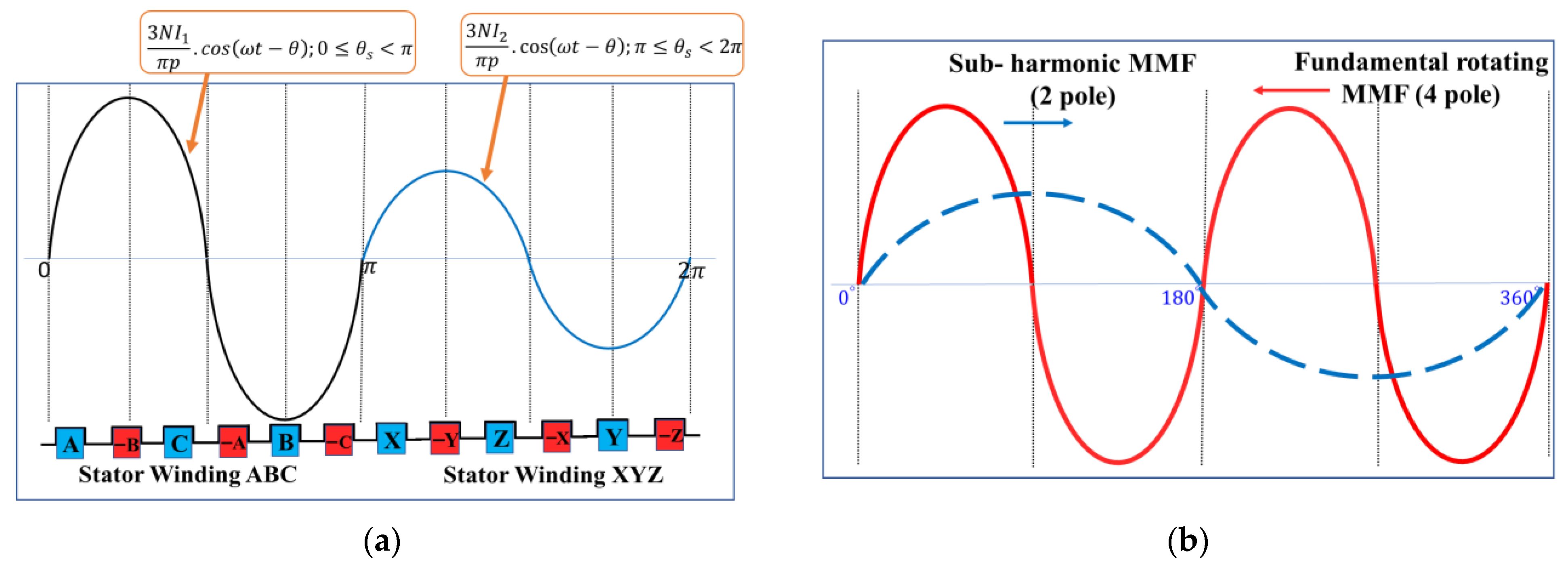
A WRSM drive scheme and 2D model based on subharmonic field excitation are shown in Figure 1, and the machine parameters are given in Table 1. Two inverters supply currents to two sets of three-phase stator armature windings, each with a separate neutral connection. The resulting air gap magnetic field in two portions of the machine is illustrated in Figure 2a. However, when it is decomposed as a Fourier series, two main magnetic field components can be observed as illustrated in Figure 2b. The two magnetic fields exist in the same air gap. Hence, the interaction of both fields generated from the stator side will interact with the rotor of the machine. It must be noted that in the proposed machine, the harmonic winding and the field winding share the limited rotor slot space which simultaneously interact with the two superimposed air gap magnetic fields. Higher harmonic current levels may result in superposition effects, influencing both slot harmonics and thermal performance. However, potential design approaches that can balance winding space utilization with harmonic suppression can be adopted. Some of them are discussed as follows:
  • Layered winding arrangement: By placing the harmonic winding and the field winding in separate radial layers within the slot, mutual interference can be reduced. This configuration also helps manage insulation stress and thermal dissipation.
  • Magnetic barriers or slot wedges: Introducing magnetic barriers (such as low-permeability slot liners or flux diverters) can reduce the coupling of higher-order harmonics while preserving available copper space for the windings.
  • Optimized slot geometry: Adjusting slot opening and tooth width allows for a trade-off between winding accommodation and harmonic suppression without significantly increasing rotor size.
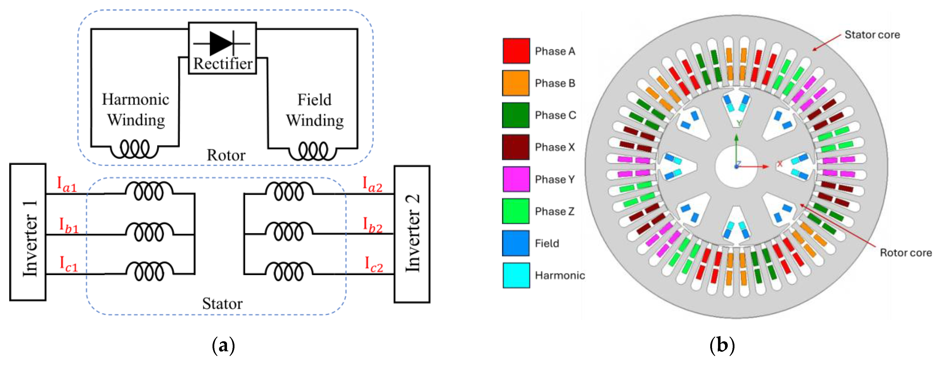
Figure 1. (a) Topology. (b) Stator winding configuration [44].
Magnetism 05 00026 g001
Figure 2. Waveform illustration of the MMF (a) based on winding configuration of ABC and XYZ and (b) decomposition into fundamental and subharmonic components.
Magnetism 05 00026 g002
Table 1. Design parameters of the machine.
ParameterValueUnit
Stator outer diameter120mm
Stator inner diameter72mm
Air gap length1mm
Stack length120mm
Number of slots48-
Number of poles8-
Base speed900-
Core materialM-19-
These approaches are feasible and worth exploring to further improve harmonic suppression and space utilization. A general flow of fundamental and subharmonic magnetic fields and their interaction with the machine components is shown in Figure 3. It is important that for maximum harmonic power transfer, the two-pole field should be maximally coupled with the harmonic winding of the rotor.
Currents from both inverters are given as
I A = I 1 sin ω e t I B = I 1 sin ( ω e t 2 π 3 ) I C = I 1 sin ( ω e t + 2 π 3 )
I X = m I 2 sin ω e t I Y = m I 2 sin ( ω e t 2 π 3 ) I Z = m I 2 sin ( ω e t + 2 π 3 )
where I1 and I2 are used to denote the amplitude of the fundamental currents of ABC-winding and XYZ-winding, respectively, m is the coefficient of difference between the currents I1 and I2, and ωe is the electrical angular frequency. The back-EMF of the machine can be calculated from a general form such as
E p h = 4.44 k w f N ϕ
where k w is winding factor, N is the number of turns per phase, and ϕ is flux per pole. When a current is injected into the armature phase windings, a rotating electromagnetic torque is produced due to the interaction between the magnetic field produced by the current and the rotor magnetic field, which is calculated as
T = 3 E p h I p h cos φ ω r
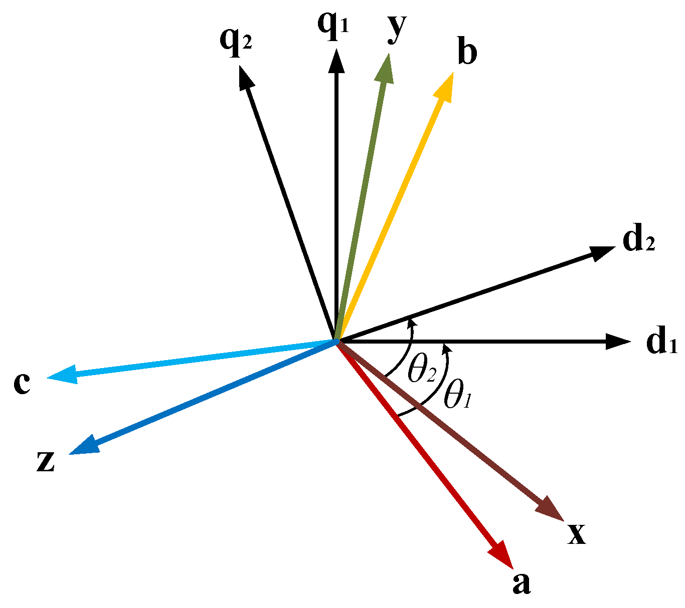
where I p h is the phase current, and φ is the power factor angle. The dual three-phase quantities are converted into the dq reference frame, as shown in Figure 4, using Park’s transformation matrix Pdq for simplicity, identifying the control and state vectors. Accordingly, the DQ reference frame’s currents and voltages will be
I d 1 I q 1 I d 2 I q 2 = P d q . I a I b I c I x I y I z ;   V d 1 V q 1 V d 2 V q 2 = P d q . V a V b V c V x V y V z
where P d q is given as
P d q = 2 3 cos θ 1 cos θ 1 2 π 3 cos θ 1 + 2 π 3 cos θ 2 cos θ 2 2 π 3 cos θ 2 + 2 π 3 sin θ 1 sin θ 1 2 π 3 sin θ 1 2 π 3 sin θ 2 sin θ 2 2 π 3 sin θ 2 2 π 3
The two sets are wound alternately on the stator teeth so that from 0 to π/2 radians spatial angle, the MMF is generated with winding set ABC, and from π/2 to π radians the MMF is generated with winding set XYZ. The configuration repeats through angle π to 2π radians for an eight-pole synchronous machine, as shown in Figure 1 and Figure 2. From the basic topology, it is shown that an additional air gap MMF of subharmonic frequency will exist with the given winding configuration when the machine is supplied with two different amplitude currents from the two inverters. The additional MMF component is then utilized to induce a voltage on a harmonic winding on the rotor. The harmonic winding works as a source for field winding excitation. Eventually, the external DC voltage source, along with the sliprings and brushes can be removed. The equation for the rotating MMF in both the ABC and XYZ parts of the machine is calculated from the MMF equation of conventional WRSM. Neglecting the effect of harmonics, the MMF equation for the rotating flux is derived by
F t o t a l = 3 N I 1 π p cos ( ω t θ ) ; 0 θ s < π 3 N I 2 π p cos ( ω t θ ) ; π θ s < 2 π
where N is the number of turns, I1 is the peak current in winding set ABC, I2 is the peak current in winding set XYZ, p is pole pairs, ω is mechanical speed, t is time, and θs is the spatial angle.
The MMF from 0 to π radian is generated by ABC currents, and from π to 2π radian, the MMF is generated by XYZ currents as illustrated in Figure 2a. Neglecting the higher harmonics, the composite MMF can be decomposed into fundamental and subharmonic components as illustrated in Figure 2b. The fundamental component of the MMF is employed to produce torque by synchronizing with the field winding flux, while the subharmonic component induces voltage in a harmonic winding on the rotor, which has half the number of poles of the field winding. The voltage induced in the rotor’s harmonic winding can be calculated as
V h = K . ω λ s u b
where K is the subharmonic coupling factor and λ s u b is the flux linkage of the harmonic winding with the subharmonic air gap magnetic field. This voltage is rectified to energize the field winding from the rotating rectifier mounted on the same rotor connected with both the rotor windings. The rectifier connection with both the field winding and the harmonic winding is shown in Figure 5.
With the diode forward voltage V D being constant for the semiconductor material used, the voltage across the field winding can be approximated as
V f 2 V h R M S 2 V D
where V h R M S is the rms value of voltage across the harmonic winding. As the closed-circuit rotor allows current to flow in the field winding, a uniform magnetic flux is generated to achieve brushless operation and develop torque. Hence, it can be extracted from (9) that the field voltage is directly proportional to the induced harmonic voltage, which is directly proportional to the ratio m controlled by the difference between the currents from the two inverters.
V f V h R M S
Therefore,
V f m
It is also important to note that feeding the proposed machine with a dual-inverter may exacerbate current harmonics if no countermeasures are taken. Several current control strategies have been reported in the literature to suppress undesired harmonic components while maintaining the subharmonic excitation required for brushless operation. Selective Harmonic Elimination (SHE) and optimized PWM patterns can be employed to eliminate specific low-order harmonics at the inverter side while retaining the target subharmonic component. Model Predictive Control (MPC) methods, including finite-control-set MPC, can minimize harmonic currents and torque ripple by directly optimizing inverter switching states [45]. Resonant and adaptive resonant current controllers are also effective in suppressing defined harmonic orders in the air gap while allowing the desired subharmonic to persist. Other options include predictive harmonic current control with disturbance observers for fast compensation, and the use of virtual impedance or adaptive virtual harmonic resistors to attenuate problematic harmonic frequencies. In practice, such active control methods can be complemented with modest passive measures such as phase reactors or small L-filters to further reduce iron loss and torque ripple. A comprehensive comparison of these algorithms and their implementation for dual-inverter WRSM drives is left for future work, as it requires detailed controller design and experimental validation beyond the steady-state analysis presented here.
In addition to conventional PWM and resonant control strategies, recent work has demonstrated more advanced methods for harmonic disturbance suppression. For example, predictive current control with selective harmonic mitigation has been shown to effectively reduce harmonic distortion in multiphase drives [46], while adaptive current regulation schemes have been applied to suppress torque ripple and iron losses across varying operating conditions [45]. These approaches offer promising prospects for extending the present dual-inverter WRSM toward enhanced harmonic robustness.

3. Effect of Harmonic Winding Turns with Fixed Field Winding Turns

Since field winding turns are not changed in this case, harmonic winding turns are varied, with a lower number of turns having a higher value of current. Therefore, copper loss due to high current in the harmonic winding increases exponentially, whereas the decrease in copper loss is only linear due to a lower number of harmonic winding turns. The copper loss in the harmonic winding is
P C H = I H 2 R P C H = I H 2 ρ N c L t A w
where IH is the RMS value of harmonic winding current, R is the total resistance of the harmonic winding, ρ is the resistivity of copper material, and Lt is the average length of the conductor, including end turn length. Since the average length of the conductor and the resistivity of copper can be constant, Equation (12) can be rewritten as
P C H = I H 2 N c A w × Constant
Thus, to keep the power loss limited to a constant value, the cross-sectional area of the conductor will have to be increased as the number of harmonic winding conductors decreases. Therefore,
A w I H 2 × N c
However, Equation (14) can be considered to keep the copper loss constant, which may affect the fill factor of the rotor given by
F i l l F a c t o r = A w × N c A s l o t
where Aw is the cross-sectional area of the conductor, Nc is the number of conductors per slot, and Aslot is the area of the slot. Therefore, for a given fill factor,
A w × N c = F i l l F a c t o r × A s l o t = Constant A w × N c = Constant

3.1. Turn Variations in Harmonic Winding with a Different Number of Armature Windings

An eight-pole 48-slot machine model was used for finite-element analysis (FEA), and the results are shown in Figure 6. As the harmonic winding turns are increased from 2 turns per pole to 16 turns per pole, the harmonic winding current, field winding current, and the torque, as shown in Figure 6a–c, respectively, vary with a non-linear pattern. Since the harmonic current varies with respect to the number of harmonic winding turns, the field current, which is rectified and fed to the field winding also varies accordingly. Similarly, the torque of the machine also varies since the field current varies.
The simulation results show that the harmonic current increases with a lower number of turns of harmonic winding until four turns per pole. Similar results are obtained at different numbers of armature winding turns. However, less than four harmonic turns affect the current decrease. It is obtained from the simulation results that for the referred machine parameters, if only the harmonic winding turns are decreased to four turns, the maximum harmonic and field currents are obtained, and eventually, the torque output can be increased. At the same time, however, the copper losses of both the rotor windings, the harmonic and field winding, will increase due to increased current, and the current density will also increase, which can create rotor heating and insulation problems in the rotor windings.

3.2. Turn Variations in Harmonic Winding with the Same Number of Armature Winding Turns

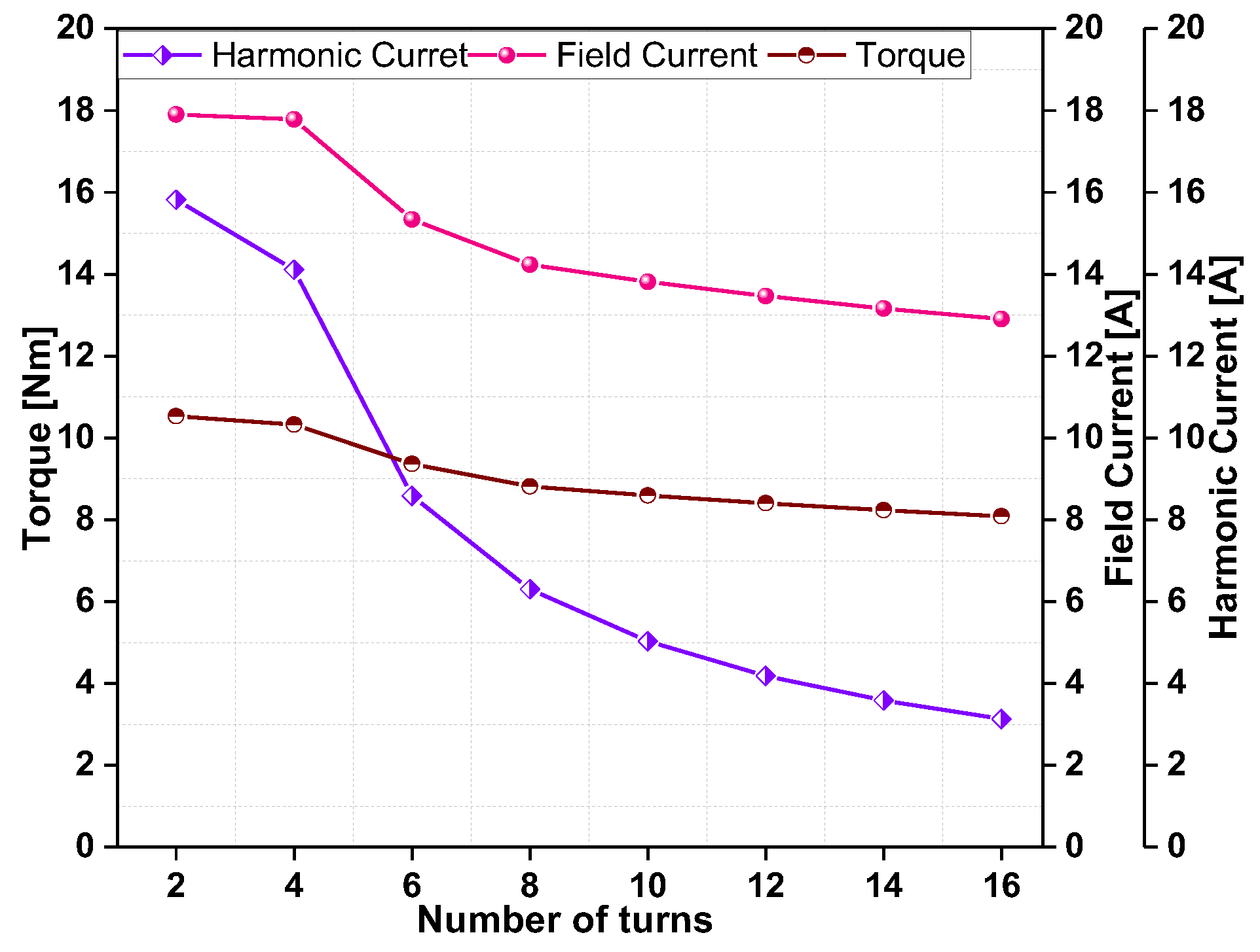
The results indicate that the harmonic current decreases as the turns for harmonic winding is reduced to a certain number of turns. Neglecting the difference in harmonic power extraction from the air gap flux due to a change in the number of turns, the decrease in the number of turns increases the current to be equal to the power extraction. Keeping in mind the voltage limits of harmonic winding and the current density limit, the number of turns of harmonic winding is kept at four turns per harmonic pole. The limit is decided by the upper limit of current in the harmonic winding, which increases the field current, and eventually, a maximum torque average is achieved. It is established that for given design parameters, increasing the number of turns results in higher field current and average torque. Figure 7 shows the variation in harmonic and field winding currents and the output torque at different numbers of harmonic winding turns.
It can be observed that the currents and the torque output are highest at the lowest number of harmonic winding turns. However, it should also be noted that there will be a limit on the lowest number of harmonic winding turns used for a given design parameter of the machine owing to increased copper losses, which generate heat and higher current density, which requires a higher diameter of the winding conductors.

4. Effect of Harmonic Winding Turns Considering Variation in Field Winding Turns

Consider that the same diameter of the harmonic winding space created by using a lower number of harmonic winding turns can be used to increase the field winding turns by the same number. In this case, a constant fill factor is considered instead of copper loss.

4.1. Turn Variations in Harmonic Winding with a Different Number of Armature Windings

It can be observed from the results, as shown in Figure 8, that the harmonic current variation curves show approximately the same pattern as in the case where field turns are kept the same, as shown in Figure 6. It can be deduced that the harmonic current is not affected by the turn variation in the field winding. However, the same power is being fed to the field winding. Since the current of the harmonic winding decreases as the number of turns is increased, the voltage should also change accordingly.
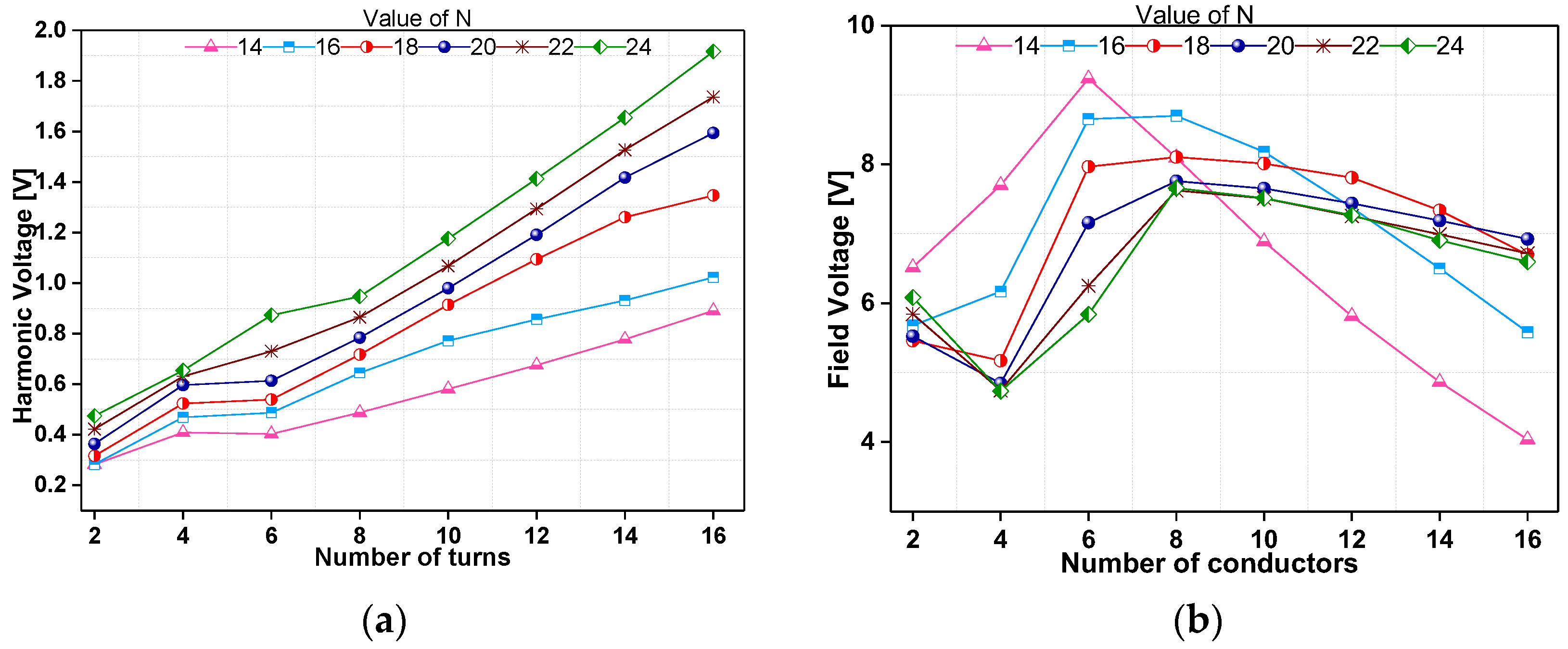
Since the harmonic component of the air gap flux resulting from the stator winding currents did not change, it should induce the same power in the harmonic winding of the rotor. As shown in Figure 9, the voltage increases in the harmonic winding as the current decreases while changing the number of turns. However, this pattern is not observed in the voltage waveforms of the field winding. This discrepancy arises from the self-induced voltage generated by the tooth-harmonic fields, which adds an extra component. As a result, the total voltage across the field winding does not exhibit the regular pattern seen in the harmonic winding voltage.

4.2. Turn Variations in Harmonic Winding with the Same Number of Armature Winding Turns

Figure 10 shows the obtained current variation curves and the output torque curve with varying harmonic winding turns. In this case, the basic machine model is considered, with 20 armature winding turns, and the field winding turns are adjusted according to the available space in the rotor, considering the fill factor.
It can be observed that torque varies approximately linearly with respect to harmonic winding turns, with a higher torque at a lower number of harmonic winding turns. However, the current in the harmonic winding increases exponentially until the harmonic winding number of turns is four. Similarly, the field winding current changes irregularly from 2 to 4 turns but tends to change linearly after 6 to 16 turns. As discussed in the previous sections, smaller turns should be kept to increase torque output, given the limits of rotor copper loss and fill factor.
The stator and rotor cores were modeled using M-19 grade non-oriented silicon steel, selected for its favorable compromise between low core losses and high magnetic saturation capability, which is appropriate for medium-speed synchronous machines. The stator employs semi-closed rectangular slots designed to reduce leakage while maintaining structural strength, whereas the rotor slots are rectangular with rounded corners to facilitate placement of both the harmonic and field windings. The effective slot fill factor used in the finite-element model was approximately 0.5.
To provide further insight into electromagnetic behavior, Figure 11 illustrates the finite-element distribution of magnetic vector potential and flux density in the machine cross-section. The plot confirms the expected flux paths in both the stator and rotor, as well as the effective coupling of the subharmonic stator MMF with the rotor harmonic winding.

5. Conclusions

This paper describes the analysis of the effect of changing the rotor’s harmonic winding turns to obtain high output torque. The factors limiting the performance based on harmonic winding turns were analyzed, which depict the relationship of the harmonic winding turns with the currents in both harmonic and field windings and the output torque of a WRSM. The effect of the number of harmonic winding turns is analyzed by changing the harmonic winding turns at different armature winding turns, keeping the field winding turns constant in one section and varying the field winding turns with respect to the available rotor slot space. It is found that the currents in the rotor harmonic winding and field winding are not linearly dependent on the number of turns of the harmonic winding. Eventually, the torque is dependent on the field current but not on the turn variation directly. However, the results show a comprehensive pattern that can be used to design the machine parameters while fixing the number of harmonic winding turns within the constraints of the rated parameters.
While this paper has focused on steady-state characteristics at rated speeds to establish the feasibility of the proposed brushless harmonic excitation scheme, several aspects remain open for future work. Dynamic performance under starting low-speed, torque ripple analysis across transient operating ranges, and high-speed field-weakening operations will be investigated in subsequent studies. Moreover, to mitigate additional harmonic components that may arise in the dual-inverter system, current control strategies such as SHE, MPC, and resonant or predictive harmonic controllers, combined with virtual impedance methods or modest passive filtering, will be explored. These measures are expected to further enhance efficiency and suppress torque ripple while maintaining the required subharmonic excitation for brushless operation.
Overall, the proposed design establishes a practical foundation for brushless WRSM excitation, with clear pathways identified for extending the approach to dynamic and wide-speed operation in future work.
These results not only confirm the effectiveness of the proposed motor design but also provide a comprehensive understanding of its magnetic behavior, supporting future optimization and practical implementation.

Author Contributions

Conceptualization, A.A. and G.J.S.; methodology, F.A. and Z.A.; software, A.A. and Z.A.; validation, A.A., F.A. and G.J.S.; formal analysis, A.A. and Z.A.; investigation, A.A., F.A., G.J.S. and Z.A.; resources, A.A., F.A., G.J.S. and Z.A.; data curation, A.A., M.S. and Q.A.; writing—original draft preparation, A.A., F.A. and G.J.S.; writing—review and editing, G.J.S., Z.A. and M.S.; visualization, A.A., G.J.S., Z.A., Q.A. and M.S.; supervision, A.A., G.J.S., Z.A. and M.U.; project administration, Z.A., M.S. and M.U.; funding acquisition, Z.A. and M.S. All authors have read and agreed to the published version of the manuscript.

Funding

This research received no external funding.

Institutional Review Board Statement

Not applicable.

Informed Consent Statement

Not applicable.

Data Availability Statement

The data will be made available upon request.

Conflicts of Interest

The authors declare no conflicts of interest.

Abbreviations

The following abbreviations are used in this manuscript:
PMPermanent magnet
IPMSMInterior permanent magnet synchronous machine
WRSMWound rotor synchronous machine
MMFMagnetomotive force
Back-EMFBack electromotive force
DQDirect and quadrature
RMSRoot-mean-squared
FEAFinite-element analysis
PWMPulse width modulation
SHESelective Harmonic Elimination
MPCModel Predictive Control

References

  1. Scaglione, G.; Nevoloso, C.; Schettino, G.; Tommaso, A.O.D.; Miceli, R. A Novel Multiobjective Finite Control Set Model Predictive Control for IPMSM Drive Fed by A Five-Level Cascaded H-Bridge Inverter. IEEE J. Emerg. Sel. Top. Power Electron. 2024, 12, 1959–1973. [Google Scholar] [CrossRef]
  2. Rahman, M.M.; Uddin, M.N. Third harmonic injection based nonlinear control of IPMSM drive for wide speed range operation. In Proceedings of the 2017 IEEE Industry Applications Society Annual Meeting, Cincinnati, OH, USA, 1–5 October 2017; pp. 1–8. [Google Scholar] [CrossRef]
  3. Zhao, X.; Niu, S. A New Slot-PM Vernier Reluctance Machine with Enhanced Zero-Sequence Current Excitation for Electric Vehicle Propulsion. IEEE Trans. Ind. Electron. 2020, 67, 3528–3539. [Google Scholar] [CrossRef]
  4. Arif, A.; Baloch, N.; Kwon, B.-I. Winding Switching and Turn Switching in Permanent Magnet Vernier Machines for Wide Speed Range Operation and High Efficiency. IEEE Access 2019, 7, 55344–55357. [Google Scholar] [CrossRef]
  5. Chai, W.; Cai, Z.; Kwon, B.-I.; Kwon, J.-W. Design of A Novel Low-Cost Consequent-Pole Permanent Magnet Synchronous Machine. IEEE Access 2020, 8, 194251–194259. [Google Scholar] [CrossRef]
  6. Sirewal, G.J.; Bukhari, S.S.H. Cost-Effective Scheme for A Brushless Wound Rotor Synchronous Machine. World Electr. Veh. J. 2021, 12, 194. [Google Scholar] [CrossRef]
  7. Edmondson, J. Will Rare-Earths Be Eliminated in Electric Vehicle Motors? Available online: https://www.idtechex.com/en/research-article/will-rare-earths-be-eliminated-in-electric-vehicle-motors/21972 (accessed on 1 October 2025).
  8. Kaya, E.E.; Kaya, O.; Stopic, S.; Gürmen, S.; Friedrich, B. NdFeB Magnets Recycling Process: An Alternative Method to Produce Mixed Rare Earth Oxide from Scrap NdFeB Magnets. Metals 2021, 11, 716. [Google Scholar] [CrossRef]
  9. Rare Earths Trade Dispute. Wikipedia. Available online: https://en.wikipedia.org/wiki/Rare_earths_trade_dispute (accessed on 1 October 2025).
  10. Seyedi, S.M.; Talebi, D.; Toliyat, H.A. A PM-Free Brushless Synchronous Machine with A Novel Compensated Wound-Field Excited by Modulated Rotating Magnetic Flux. IEEE Trans. Energy Convers. 2024, 39, 2068–2080. [Google Scholar] [CrossRef]
  11. Lipo, T.A.; Du, Z.S. Synchronous motor drives—A forgotten option. In Proceedings of the 2015 Intl Aegean Conference on Electrical Machines & Power Electronics (ACEMP), 2015 Intl Conference on Optimization of Electrical & Electronic Equipment (OPTIM) & 2015 Intl Symposium on Advanced Electromechanical Motion Systems (ELECTROMOTION), Side, Türkiye, 2–4 September 2015; pp. 1–5. [Google Scholar] [CrossRef]
  12. Dmitrievskii, V.; Prakht, V.; Valeev, E.; Paramonov, A.; Kazakbaev, V.; Anuchin, A. Comparative Study of Induction and Wound Rotor Synchronous Motors for the Traction Drive of a Mining Dump Truck Operating in Wide Constant Power Speed Range. IEEE Access 2023, 11, 68395–68409. [Google Scholar] [CrossRef]
  13. Chen, H.; Tang, J.; Liu, Y.; Jiang, B.; Boscaglia, L. Electromagnetic Performance Investigation of a Brushless Electrically Excited Synchronous Machine for Long-Distance Heavy-Duty Electric Vehicles. IEEE Trans. Transp. Electrif. 2025, 11, 225–235. [Google Scholar] [CrossRef]
  14. Bian, W.; Zhang, Z.; Li, L.; Jin, C.; Li, J.; Guo, F. An Approximate Three-Phase AC Excitation Method with Parallel Capacitors for Aircraft Wound Rotor Synchronous Starter/Generator. IEEE Trans. Transp. Electrif. 2025, 11, 5497–5508. [Google Scholar] [CrossRef]
  15. Graffeo, F.; Vaschetto, S.; Tenconi, A.; Cavagnino, A. Fast Sizing Procedure for Salient-Pole Wound Field Synchronous Motors for Transportation Electrification. In Proceedings of the 2023 IEEE International Electric Machines & Drives Conference (IEMDC), San Francisco, CA, USA, 15–18 May 2023; pp. 1–7. [Google Scholar] [CrossRef]
  16. Akuru, U.B.; Ullah, W.; Okojie, D.E.; Masisi, L.; Idoko, H.C.; Khan, F. Comparative Performance Evaluation, Prototyping and Experimentation of the Double-Stator Wound-Field Flux Switching Machine. IEEE Trans. Ind. Appl. 2024, 60, 6706–6714. [Google Scholar] [CrossRef]
  17. Nguyen, M.-D.; Hoang, D.-T.; Kim, S.-M.; Jung, W.-S.; Shin, K.-H.; Kim, Y.-J. Nonlinear Modeling and Analysis Considering Coupling Stator Flux of Wound-Rotor Synchronous Motors. In Proceedings of the 2024 International Conference on Electrical Machines (ICEM), Torino, Italy, 1–4 September 2024; pp. 1–7. [Google Scholar] [CrossRef]
  18. Li, Y.; Wang, Y.; Zhang, Z.; Li, J. Investigation and Development of the Brushless and Magnetless Wound Field Synchronous Motor Drive System for Electric Vehicle Application. World Electr. Veh. J. 2023, 14, 81. [Google Scholar] [CrossRef]
  19. Dorrell, D.G. Are wound-rotor synchronous motors suitable for use in high efficiency torque-dense automotive drives? In Proceedings of the IECON 2012—38th Annual Conference on IEEE Industrial Electronics Society, Montreal, QC, Canada, 25–28 October 2012; pp. 4880–4885. [Google Scholar] [CrossRef]
  20. Laldin, O.; Sudhoff, S.D.; Pekarek, S. An Analytical Design Model for Wound Rotor Synchronous Machines. IEEE Trans. Energy Convers. 2015, 30, 1299–1309. [Google Scholar] [CrossRef]
  21. Liu, W.; Lipo, T.A. Saliency enhancement of salient pole wound field synchronous machines for variable speed applications. In Proceedings of the 2017 IEEE International Electric Machines and Drives Conference (IEMDC), Miami, FL, USA, 21–24 May 2017. [Google Scholar] [CrossRef]
  22. Sirewal, G.J.; Choi, G. Analysis and Design of a Self-Excitation Scheme for An Open-End Armature Winding Wound-Rotor Synchronous Machine. In Proceedings of the 2024 IEEE Energy Conversion Congress and Exposition (ECCE), Phoenix, AZ, USA, 20–24 October 2024; pp. 5846–5851. [Google Scholar] [CrossRef]
  23. Sirewal, G.J.; Kim, E.; Choi, G. Dual Inverter Controlled Third Harmonic Current Injection Scheme for an Open-End Winding Brushless Wound Rotor Synchronous Machine. In Proceedings of the 2024 27th International Conference on Electrical Machines and Systems (ICEMS), Fukuoka, Japan, 26–29 November 2024; pp. 3374–3380. [Google Scholar] [CrossRef]
  24. Wang, X.; Xiong, Z.; Jiang, H.; Li, Y.; Lin, X.; Xie, W. Field Oriented Control Strategy for Five-Phase Self-Excited Synchronous Motor Based on Injecting High-Frequency Current. In Proceedings of the IECON 2023—49th Annual Conference of the IEEE Industrial Electronics Society, Singapore, 16–19 October 2023. [Google Scholar] [CrossRef]
  25. Cui, S.; Zhang, Y.; Song, B.; Gao, X.; Zhao, T.; Dong, S. Resonant Coupled Excitation Brushless Synchronous Motor. In Proceedings of the 2023 26th International Conference on Electrical Machines and Systems (ICEMS), Zhuhai, China, 5–8 November 2023. [Google Scholar] [CrossRef]
  26. Mao, S.; Wang, L.; Ma, C.; Zhang, S.; Liu, W. Enhanced I/F Starting Control Method of Brushless Synchronous Starter/Generator with High-Frequency Signal Injection. In Proceedings of the IECON 2023—49th Annual Conference of the IEEE Industrial Electronics Society, Singapore, 16–19 October 2023. [Google Scholar] [CrossRef]
  27. Zhu, S.; Liu, C.; Wang, K.; Zhou, Z.; Yu, J. Structure and Operating Performance of a Double Electrical Excitation Synchronous Generator with Embedded Brushless Synchronous Exciter Utilizing DC-Field Excitation. IEEE Trans. Energy Convers. 2022, 37, 50–64. [Google Scholar] [CrossRef]
  28. Jiao, N.; Liu, W.; Meng, T.; Peng, J.; Mao, S. Design and Control of a Two-Phase Brushless Exciter for Aircraft Wound-Rotor Synchronous Starter/Generator in the Starting Mode. IEEE Trans. Power Electron. 2016, 31, 4452–4461. [Google Scholar] [CrossRef]
  29. Zhang, Z.; Liu, W.; Zhao, D.; Mao, S.; Meng, T.; Jiao, N. Steady-state performance evaluations of three-phase brushless asynchronous excitation system for aircraft starter/generator. IET Electr. Power Appl. 2016, 10, 788–798. [Google Scholar] [CrossRef]
  30. Wang, L.; Cheung, R.W.; Ma, Z.; Ruan, J.; Peng, Y. Finite-Element Analysis of Unbalanced Magnetic Pull in A Large Hydro-Generator Under Practical Operations. IEEE Trans. Magn. 2008, 44, 1558–1561. [Google Scholar] [CrossRef]
  31. Kutt, F.; Michna, M.; Kostro, G. Non-Salient Brushless Synchronous Generator Main Exciter Design for More Electric Aircraft. Energies 2020, 13, 2696. [Google Scholar] [CrossRef]
  32. Yao, F.; Sun, L.; Sun, D.; Lipo, T.A. Design and Excitation Control of a Dual Three-Phase Zero-Sequence Current Starting Scheme for Integrated Starter/Generator. IEEE Trans. Ind. Appl. 2021, 57, 3776–3786. [Google Scholar] [CrossRef]
  33. Li, J.; Wang, K.; Liu, C. Improvement of Integrated-Induction-Based Hybrid Excitation Brushless DC Generator by Employing Novel Consequent-Pole Rotor. IEEE Trans. Ind. Electron. 2022, 69, 12042–12054. [Google Scholar] [CrossRef]
  34. Yao, F.; An, Q.; Gao, X.; Sun, L.; Lipo, T.A. Principle of Operation and Performance of a Synchronous Machine Employing a New Harmonic Excitation Scheme. IEEE Trans. Ind. Appl. 2015, 51, 3890–3898. [Google Scholar] [CrossRef]
  35. Jawad, G.; Ali, Q.; Lipo, T.A.; Kwon, B.-I. Novel Brushless Wound Rotor Synchronous Machine with Zero-Sequence Third-Harmonic Field Excitation. IEEE Trans. Magn. 2016, 52, 1–4. [Google Scholar] [CrossRef]
  36. Yao, F.; Sun, D.; Sun, L.; Lipo, T.A. Dual Third-Harmonic-Current Excitation Principle of a Brushless Synchronous Machine Based on Double Three-Phase Armature Windings. In Proceedings of the 2019 22nd International Conference on Electrical Machines and Systems (ICEMS), Harbin, China, 11–14 August 2019. [Google Scholar] [CrossRef]
  37. Chung, J.; Hofmann, H. Brushless Self-Excited Synchronous Field-Winding Machine with Five- and Higher-Phase Design Using Independently Controlled Spatial Harmonics. IEEE Trans. Energy Convers. 2024, 39, 533–543. [Google Scholar] [CrossRef]
  38. Ayub, M.; Sirewal, G.J.; Bukhari, S.S.H.; Kwon, B. Brushless wound rotor synchronous machine with third-harmonic field excitation. Electr. Eng. 2020, 102, 259–265. [Google Scholar] [CrossRef]
  39. Ayub, M.; Bukhari, S.S.H.; Jawad, G.; Kwon, B. Brushless wound field synchronous machine with third-harmonic field excitation using a single inverter. Electr. Eng. 2019, 101, 165–173. [Google Scholar] [CrossRef]
  40. Ayub, M.; Hussain, A.; Jawad, G.; Kwon, B.-I. Brushless operation of a wound-field synchronous machine using a novel winding scheme. IEEE Trans. Magn. 2019, 55, 1–4. [Google Scholar] [CrossRef]
  41. Bukhari, S.S.H.; Sirewal, G.J.; Ayub, M.; Ro, J.-S. A New Small-Scale Self-Excited Wound Rotor Synchronous Motor Topology. IEEE Trans. Magn. 2021, 57, 1–5. [Google Scholar] [CrossRef]
  42. Ayub, M.; Atiq, S.; Sirewal, G.J.; Kwon, B.-I. Fault-Tolerant Operation of Wound Field Synchronous Machine Using Coil Switching. IEEE Access 2019, 7, 67130–67138. [Google Scholar] [CrossRef]
  43. Hussain, A.; Baig, Z.; Toor, W.T.; Ali, U.; Idrees, M.; Shloul, T.A.; Ghadi, Y.Y.; Alkahtani, H.K. Wound Rotor Synchronous Motor as Promising Solution for Traction Applications. Electronics 2022, 11, 4116. [Google Scholar] [CrossRef]
  44. Ali, Q.; Lipo, T.A.; Kwon, B.-I. Design and Analysis of a Novel Brushless Wound Rotor Synchronous Machine. IEEE Trans. Magn. 2015, 51, 1–4. [Google Scholar] [CrossRef]
  45. Li, T.; Sun, X.; Su, Z.; Zha, X.; Dianov, A.; Prakht, V. Model-Free Predictive Control for Harmonic Suppression of PMSMs Based on Adaptive Resonant Controller. IEEE Trans. Energy Convers. 2025, 1–10. [Google Scholar] [CrossRef]
  46. Zhang, Z.; Liu, Y.; Liang, X.; Guo, H.; Zhuang, X. Robust Model Predictive Current Control of PMSM Based on Nonlinear Extended State Observer. IEEE J. Emerg. Sel. Top. Power Electron. 2023, 11, 862–873. [Google Scholar] [CrossRef]
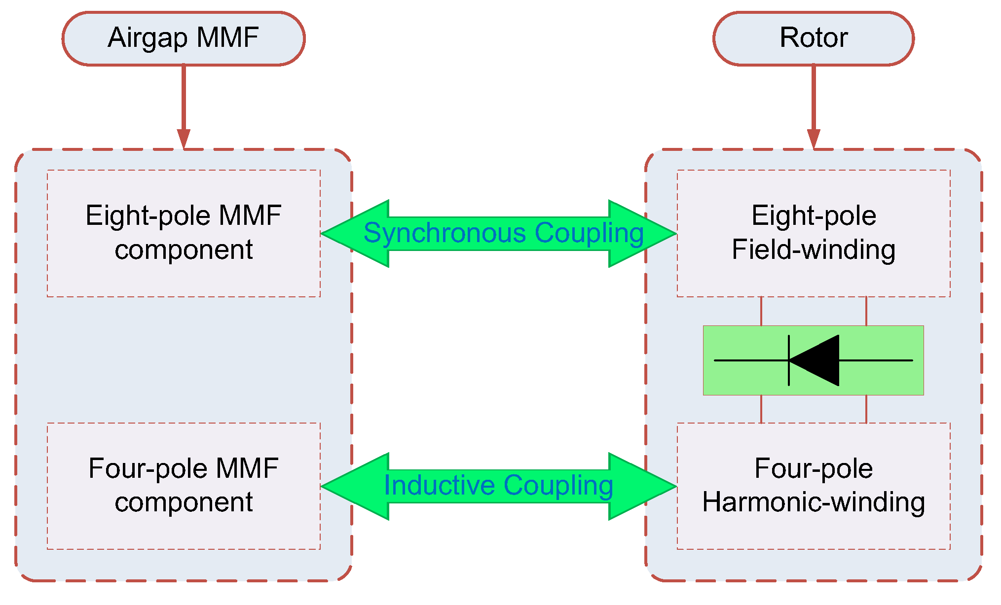
Figure 3. Illustration of the air gap magnetic fields coupling interaction with rotor windings.
Magnetism 05 00026 g003
Figure 4. Angular difference between the double three-phase windings in the ABCXYZ-frame and DQ-frame of references.
Magnetism 05 00026 g004
Figure 5. Rotor winding connection with an uncontrolled diode rectifier.
Magnetism 05 00026 g005
Figure 6. Effect of varying harmonic winding turns at different armature turns on (a) harmonic current, (b) field current, and (c) torque.
Magnetism 05 00026 g006
Figure 7. Effect of varying harmonic winding turns on harmonic current, field current, and torque at 20 turns of armature winding.
Magnetism 05 00026 g007
Figure 8. Effect of varying harmonic winding turns compensated with field winding turns on (a) harmonic current, (b) field current, and (c) torque.
Magnetism 05 00026 g008
Figure 9. Effect of varying harmonic winding turns compensated with field winding turns on (a) harmonic winding voltage and (b) field winding voltage.
Magnetism 05 00026 g009
Figure 10. Effect of varying harmonic winding turns compensated with field winding turns on harmonic current, field current, and torque at 20 turns of armature winding.
Magnetism 05 00026 g010
Figure 11. Finite-element distribution of (a) magnetic vector potential and (b) flux density in the machine cross-section, showing flux linkage between the stator-generated subharmonic field and the rotor harmonic winding.
Magnetism 05 00026 g011
Disclaimer/Publisher’s Note: The statements, opinions and data contained in all publications are solely those of the individual author(s) and contributor(s) and not of MDPI and/or the editor(s). MDPI and/or the editor(s) disclaim responsibility for any injury to people or property resulting from any ideas, methods, instructions or products referred to in the content.