

Selection of a Suitable Conductor for Inductive Power Transfer


Abstract
1. Introduction
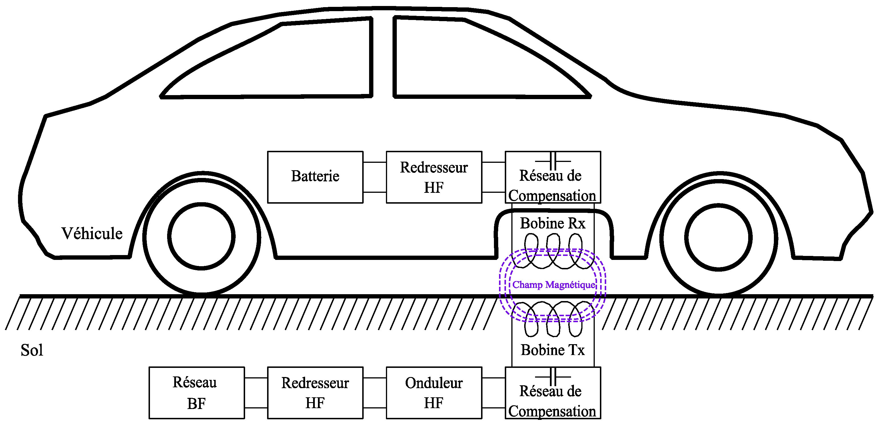
2. System Design for DIPT
2.1. Topology of the Studied IPT System Used for Comparison
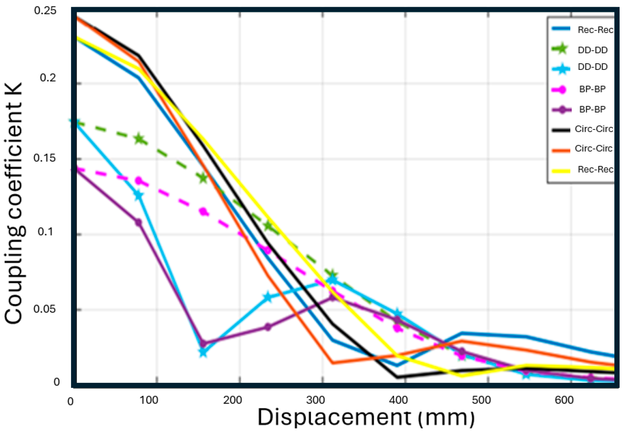
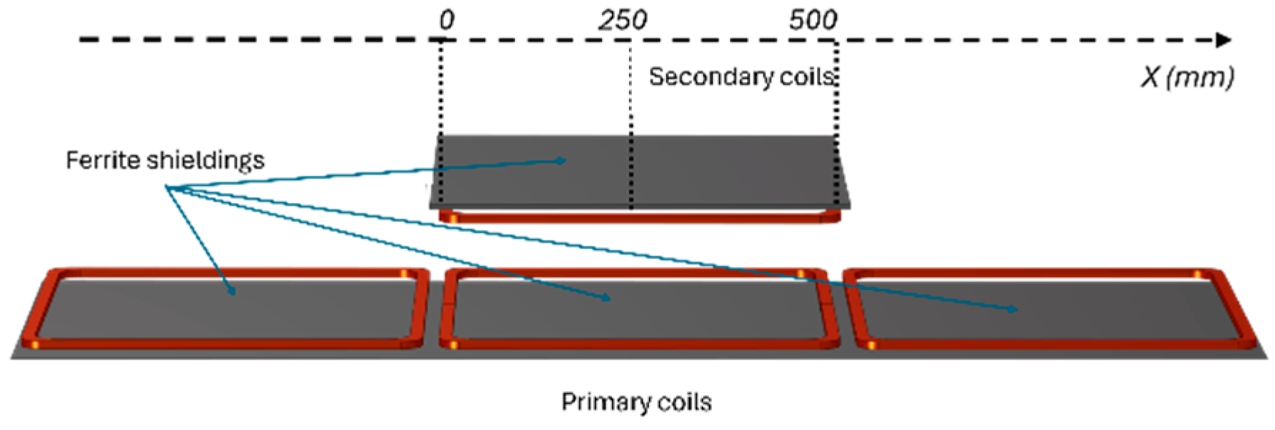
2.2. Magnetic Coupler Architecture
3. Presentation of the Reference System
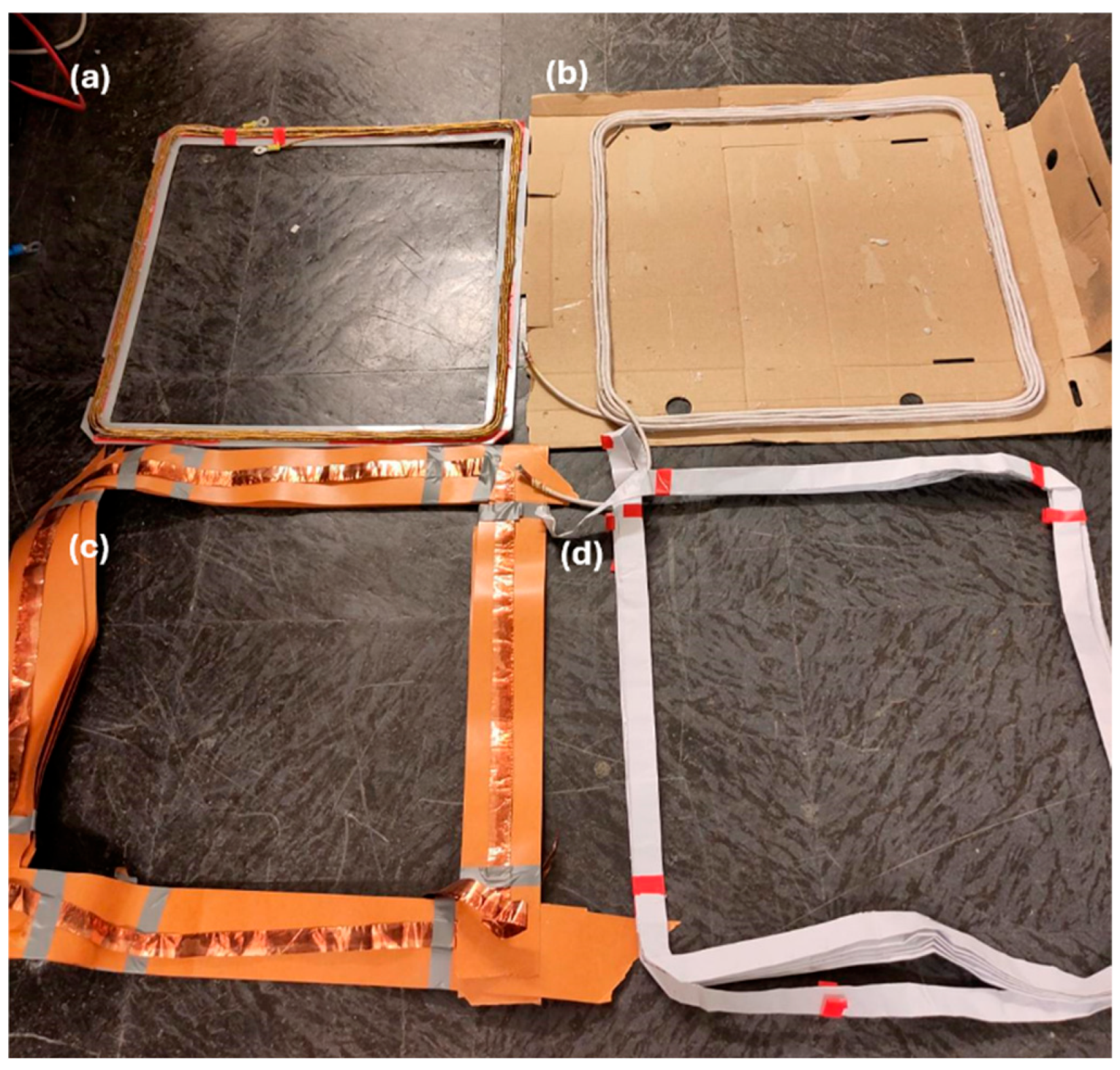
3.1. Proposed Solutions
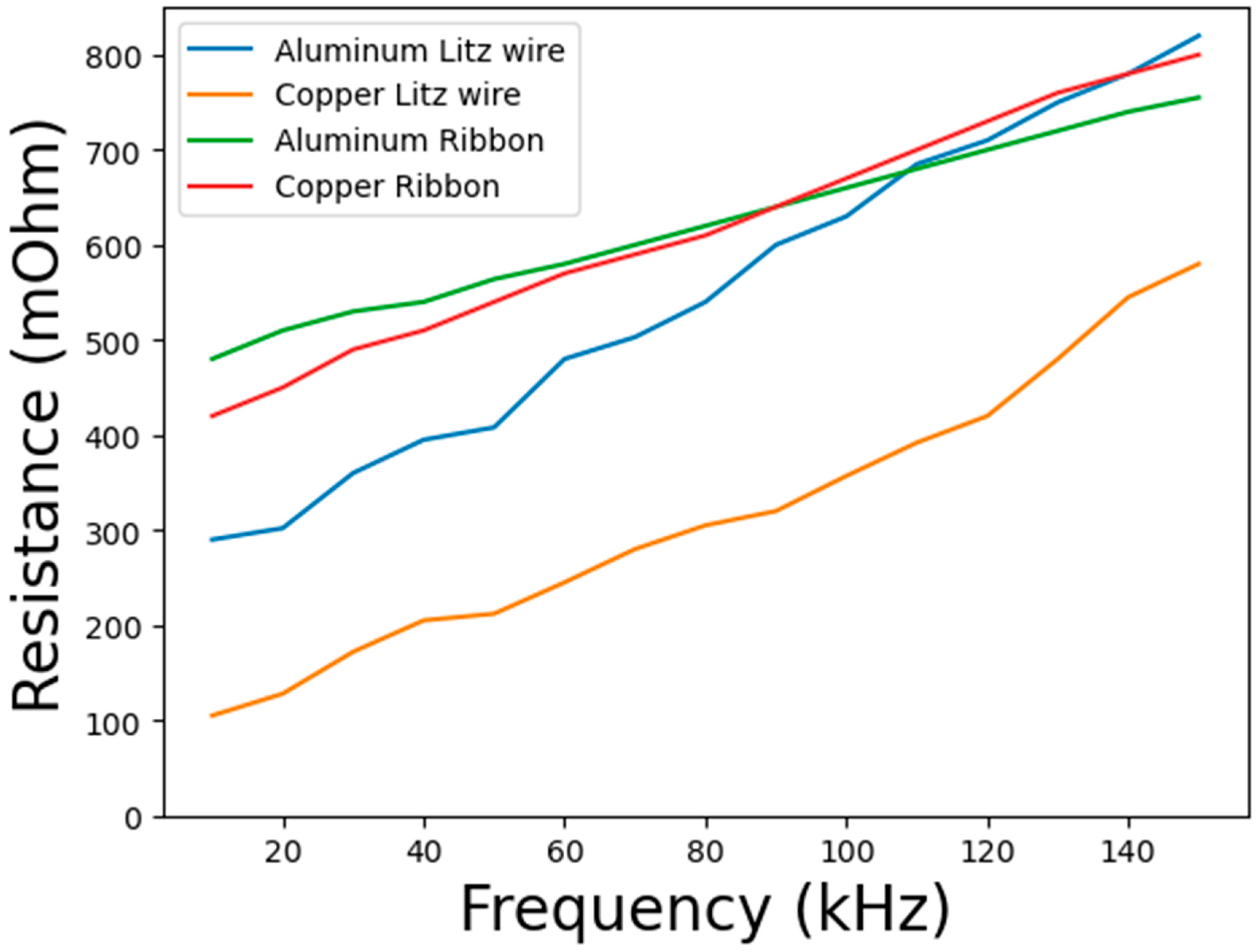
3.2. Experimental Results
4. Comparative LCA of Conductor Types
4.1. Goal and Scope Definition
4.2. Life Cycle Inventory and Assumptions
4.2.1. Litz Wire Production Process
4.2.2. Ribbon Production Process
4.3. Results and Interpretations
5. Comparison of the Results
6. Conclusions
Author Contributions
Funding
Data Availability Statement
Conflicts of Interest
References
- Fyhr, P.; Domingues, G.; Andersson, M.; Marquez-Fernandez, F.J.; Bangtsson, H.; Alakula, M. Electric roads: Reducing the societal cost of automotive electrification. In Proceedings of the 2017 IEEE Transportation Electrification Conference and Expo (ITEC), Chicago, IL, USA, 22–24 June 2017; IEEE: New York, NY, USA, 2017; pp. 773–778. [Google Scholar] [CrossRef]
- Kabbara, W.; Phulpin, T.; Bensetti, M. A Review of Standard in Inductive Power Transfer. J. Electr. Electron. Eng. 2024, 3, 1–7. [Google Scholar]
- Stankiewicz, J.M. Estimation of the Influence of the Coil Resistance on the Power and Efficiency of the WPT System. Energies 2023, 16, 6210. [Google Scholar] [CrossRef]
- Yanniello, R.; Pollak, P.; Rooks, J. Technical and Economic Considerations of Aluminum Conductors. In Proceedings of the Conference Record of 2007 Annual Pulp and Paper Industry Technical Conference, Williamsburg, VA, USA, 24–28 June 2007; IEEE: New York, NY, USA, 2007; pp. 63–67. [Google Scholar] [CrossRef]
- Sullivan, C.R. Aluminum Windings and Other Strategies for High-Frequency Magnetics Design in an Era of High Copper and Energy Costs. IEEE Trans. Power Electron. 2008, 23, 2044–2051. [Google Scholar] [CrossRef]
- Maezawa, T.; Zhou, H.; Sato, M.; Bu, Y.; Mizuno, T. Low Loss on a Litz Aluminum Wire Coil Using Magnetic Tape for Automotive Wireless Power Transmission. IEEE Trans. Magn. 2021, 57, 8700307. [Google Scholar] [CrossRef]
- Kabbara, W.; Bensetti, M.; Phulpin, T.; Caillierez, A.; Sadarnac, S.L.E.D. A Control Strategy to Avoid Drop and Inrush Currents during Transient Phases in a Multi-Transmitters DIPT System. Energies 2022, 15, 2911. [Google Scholar] [CrossRef]
- Busacca, A.; Tommaso, A.O.D.; Campagna, N.; Miceli, R.; Valtchev, V.C.S. Design and Validation of a Dynamic Inductive Power Transfer System for EV Battery Charging. In Proceedings of the 2022 Second International Conference on Sustainable Mobility Applications, Renewables and Technology (SMART), Cassino, Italy, 23–25 November 2022; pp. 1–5. [Google Scholar] [CrossRef]
- Ge, X.; Wang, Y.; Ren, D.; Tang, M.; Wang, L. A Single-Input Multi-Output Inverter with Voltage Boosting for Multi-Load Wireless Power Transfer Systems. Appl. Sci. 2024, 14, 10453. [Google Scholar] [CrossRef]
- Kabbara, W.; Bensetti, M.; Phulpin, T.; Sadarnac, D.; Caillierez, A.; Loudot, S. First Harmonic Approximation of a Full Bridge Rectifier with a Weak Capacitive Filter. In Proceedings of the Journées Scientifiques URSI-France 2023, L’ÉNERGIE AU CŒUR DES ONDES RESSOURCES ET ENVIRONNEMENT: GESTION “INTELLIGENTE” ⟨hal-04042964⟩, Gif-Sur-Yvettes, France, 21–22 March 2023; Available online: https://hal.science/hal-04042964/ (accessed on 11 December 2024).
- Kadem, K.; Bensetti, M.; Le Bihan, Y.; Labouré, E.; Debbou, M. Optimal Coupler Topology for Dynamic Wireless Power Transfer for Electric Vehicle. Energies 2021, 14, 3983. [Google Scholar] [CrossRef]
- Edwards, T.C.; Steer, M.B. Foundations for Microstrip Circuit Design, 1st ed.; Wiley: Hoboken, NJ, USA, 2016. [Google Scholar] [CrossRef]
- Carretero, C. Coupling power losses in inductive power transfer systems with Litz-wire coils. IEEE Trans. Ind. Electron. 2017, 64, 4474–4482. [Google Scholar] [CrossRef]
- Huber, J.; Imperiali, L.; Menzi, D.; Musil, F.; Kolar, J.W. Energy Efficiency is Not Enough! IEEE Power Electron. Mag. 2024, 11, 18–31. [Google Scholar] [CrossRef]
- ISO 14040:2006(E); ISO 14040: Environmental Management—Life Cycle Assessment—Principles and Framework. International Standards Organization: Geneva, Switzerland, 2006.
- ISO 14044:2006(E); ISO 14044: Environmental Management—Life Cycle Assessment—Requirements and Guidelines. International Standards Organization: Geneva, Switzerland, 2006.
- Born, H.C.; Blanc, F.S.-L.; Platte, V.; Kampker, A.; Heimes, H.; Dorn, B.; Brans, F.; Drexler, D.; Oehler, F.; zu Munster, A.; et al. Development of a Production Process for Formed Litz Wire Stator Windings. In Proceedings of the 2022 12th International Electric Drives Production Conference (EDPC), Regensburg, Germany, 29–30 November 2022; IEEE: New York, NY, USA, 2022; pp. 1–9. [Google Scholar] [CrossRef]
- Wędrychowicz, M.; Kurowiak, J.; Skrzekut, T.; Noga, P. Recycling of Electrical Cables—Current Challenges and Future Prospects. Materials 2023, 16, 6632. [Google Scholar] [CrossRef] [PubMed]
- Steubing, B.; Wernet, G.; Reinhard, J.; Bauer, C.; Moreno-Ruiz, E. The ecoinvent database version 3 (part II): Analyzing LCA results and comparison to version 2. Int. J. Life Cycle Assess. 2016, 21, 1269–1281. [Google Scholar] [CrossRef]
- Guinée, J.B.; Gorrée, M.; Heijungs, R.; Huppes, G.; Kleijn, R.; Koning, A.D.; Oers, L.V.; Wegener Sleeswijk, A.; Suh, S.; Udo de Haes, H.A.; et al. Handbook on Life Cycle Assessment. Operational Guide to the ISO Standards. I: LCA in Perspective. IIa: Guide. IIb: Operational Annex. III: Scientific Background; Kluwer Academic Publishers: Dordrecht, The Netherlands, 2002; 692p, ISBN 1-4020-0228-9. [Google Scholar]
- Born, H.C.; Oehler, F.; Platte, V.; Kampker, A.; Heimes, H.; Dorn, B.; Brans, F.; Drexler, D.; Blanc, F.S.-L.; Reising, S. Manufacturing Process and Design Requirements of Litz Wire with Focus on Efficiency Improvement of Traction Motors. In Proceedings of the 2022 12th International Electric Drives Production Conference (EDPC), Regensburg, Germany, 29–30 November 2022; IEEE: New York, NY, USA, 2022; pp. 1–7. [Google Scholar] [CrossRef]


| Requirements | Copper Litz Wire | Aluminum Litz Wire |
|---|---|---|
| Section of the conductor | 5.53 | 5.53 |
| Length of the coil | 11.52 m | 11.52 m |
| Section and Construction | 176 × 400 µm | 44 × 400 µm |
| Price for one coil | 12.79 EUR | 4.15 EUR |
| Weight for one coil | 683.67 g | 187.62 g |
| Requirements | Copper Ribbon | Aluminum Ribbon |
|---|---|---|
| Width | 50 mm | 50 mm |
| Length of the coil | 11.52 m | 11.52 m |
| Thickness | 0.05 mm | 0.2 mm |
| Breaking load | 44 N/cm | 35 N/cm |
| Service Temperature | −10 °C to +130 °C | −20 °C to +110 °C |
| Price for one coil | 10.34 EUR | 2.39 EUR |
| Weight for one coil | 281.25 g | 130.12 g |
| f (kHz) | Copper Litz Wire | Aluminum Litz Wire | Copper Ribbon | Aluminum Ribbon |
|---|---|---|---|---|
| 80 | 95.73% | 92.27% | 85.56% | 88.18% |
| 85 | 95.29% | 92.05% | 87.40% | 88.88% |
| 90 | 94.54% | 92.92% | 87.50% | 89.40% |
| Architectures | |||||
|---|---|---|---|---|---|
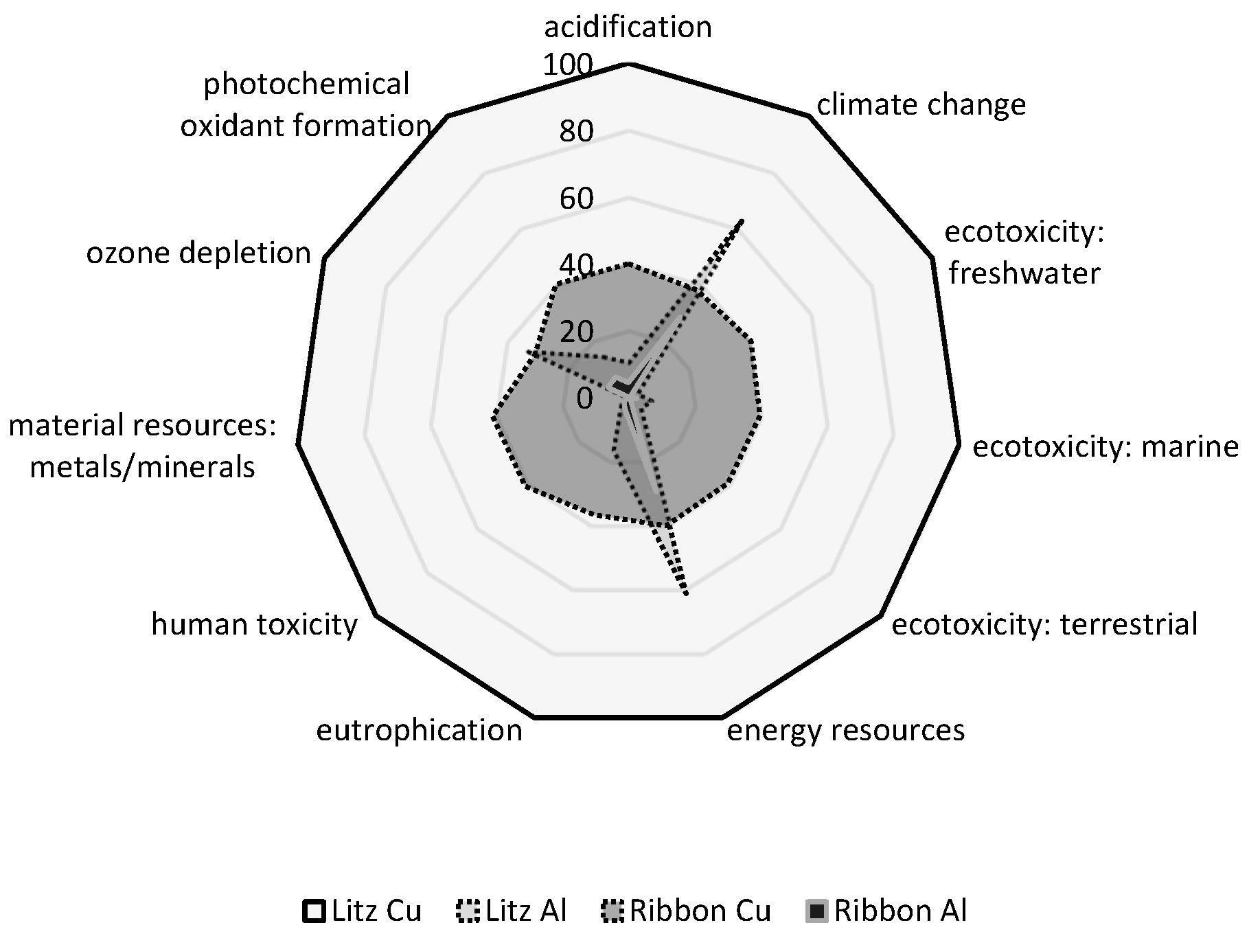
| Impact Category | Unit | Litz Cu | Litz Al | Ribbon Cu | Ribbon Al |
| acidification | kg SO2-Eq | 3.67 × 10⁻¹ | 3.88 × 10⁻² | 1.47 × 10⁻¹ | 1.59 × 10⁻² |
| climate change | kg CO2-Eq | 1.20 × 10 | 7.54 × 100 | 4.58 × 100 | 3.44 × 100 |
| ecotoxicity: freshwater | kg 1,4-DCB-Eq | 1.95 × 10² | 5.45 × 100 | 7.87 × 10 | 1.53 × 100 |
| ecotoxicity: marine | kg 1,4-DCB-Eq | 2.32 × 10⁵ | 1.61 × 10⁴ | 9.23 × 10⁴ | 5.98 × 10³ |
| ecotoxicity: terrestrial | kg 1,4-DCB-Eq | 8.63 × 10⁻¹ | 4.04 × 10⁻² | 3.40 × 10⁻¹ | 5.29 × 10⁻³ |
| energy resources | MJ | 1.47 × 10² | 8.97 × 10 | 5.88 × 10 | 4.32 × 10 |
| eutrophication | kg PO4-Eq | 1.21 × 10⁻¹ | 1.99 × 10² | 4.42 × 10⁻² | 4.42 × 10⁻³ |
| human toxicity | kg 1,4-DCB-Eq | 4.71 × 10² | 1.42 × 10 | 1.92 × 10² | 7.60 × 100 |
| material resources: metals/minerals | kg Sb-Eq | 9.03 × 10⁻³ | 2.23 × 10⁻⁵ | 3.71 × 10⁻³ | 3.25 × 10⁻⁶ |
| ozone depletion | kg CFC-11-Eq | 1.26 × 10⁻⁶ | 4.17 × 10⁻⁷ | 3.86 × 10⁻⁷ | 8.66 × 10⁻⁸ |
| photochemical oxidant formation | kg ethylene-Eq | 1.42 × 10⁻² | 2.07 × 10⁻³ | 5.70 × 10⁻³ | 1.01 × 10⁻³ |
| Conductor | Coupler Efficiency | LCA Results | Weight of a Coil | Price of a Coil |
|---|---|---|---|---|
| Copper litz wire | 95.29% | −− | 683 g | 9.79 EUR |
| Aluminium Litz wire | 92.05% (−3%) | +− | 187 g (−72%) | 4.15 EUR (−57%) |
| Copper foil | 87.40% (−8%) | +− | 281 g (−58%) | 9 EUR (−1%) |
| Aluminum foil | 88.88% (−6%) | ++ | 130 g (−80%) | 4.51 EUR (−54%) |
Disclaimer/Publisher’s Note: The statements, opinions and data contained in all publications are solely those of the individual author(s) and contributor(s) and not of MDPI and/or the editor(s). MDPI and/or the editor(s) disclaim responsibility for any injury to people or property resulting from any ideas, methods, instructions or products referred to in the content. |
© 2025 by the authors. Licensee MDPI, Basel, Switzerland. This article is an open access article distributed under the terms and conditions of the Creative Commons Attribution (CC BY) license (https://creativecommons.org/licenses/by/4.0/).
Share and Cite
Phulpin, T.; Boulahbel, R.; Randrianjanaka, H.; Leroy, Y. Selection of a Suitable Conductor for Inductive Power Transfer. Magnetism 2025, 5, 7. https://doi.org/10.3390/magnetism5010007
Phulpin T, Boulahbel R, Randrianjanaka H, Leroy Y. Selection of a Suitable Conductor for Inductive Power Transfer. Magnetism. 2025; 5(1):7. https://doi.org/10.3390/magnetism5010007
Chicago/Turabian StylePhulpin, Tanguy, Rym Boulahbel, Hafaliana Randrianjanaka, and Yann Leroy. 2025. "Selection of a Suitable Conductor for Inductive Power Transfer" Magnetism 5, no. 1: 7. https://doi.org/10.3390/magnetism5010007
APA StylePhulpin, T., Boulahbel, R., Randrianjanaka, H., & Leroy, Y. (2025). Selection of a Suitable Conductor for Inductive Power Transfer. Magnetism, 5(1), 7. https://doi.org/10.3390/magnetism5010007