
Electrically Small Wideband Monopole Antenna Partially Loaded with Low Loss Magneto-Dielectric Material


Abstract
:1. Introduction
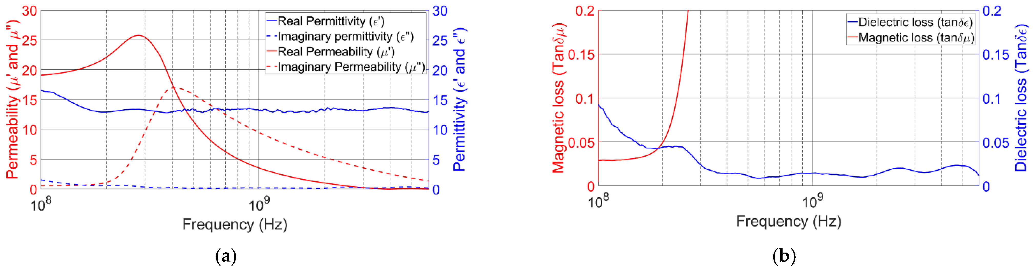
2. MDM Description
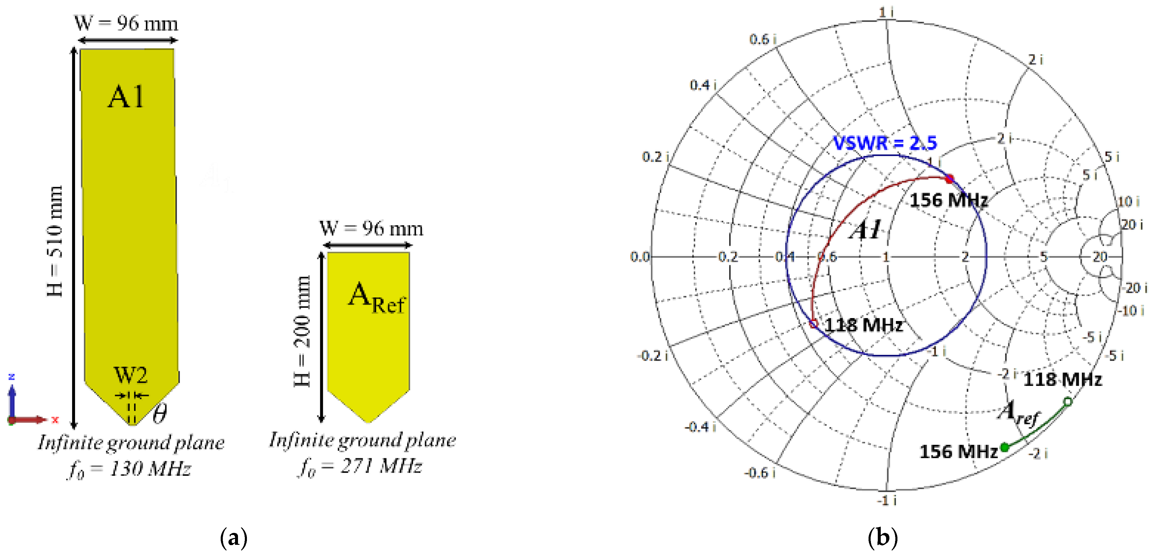
3. Geometry of the Planar Monopole Antenna
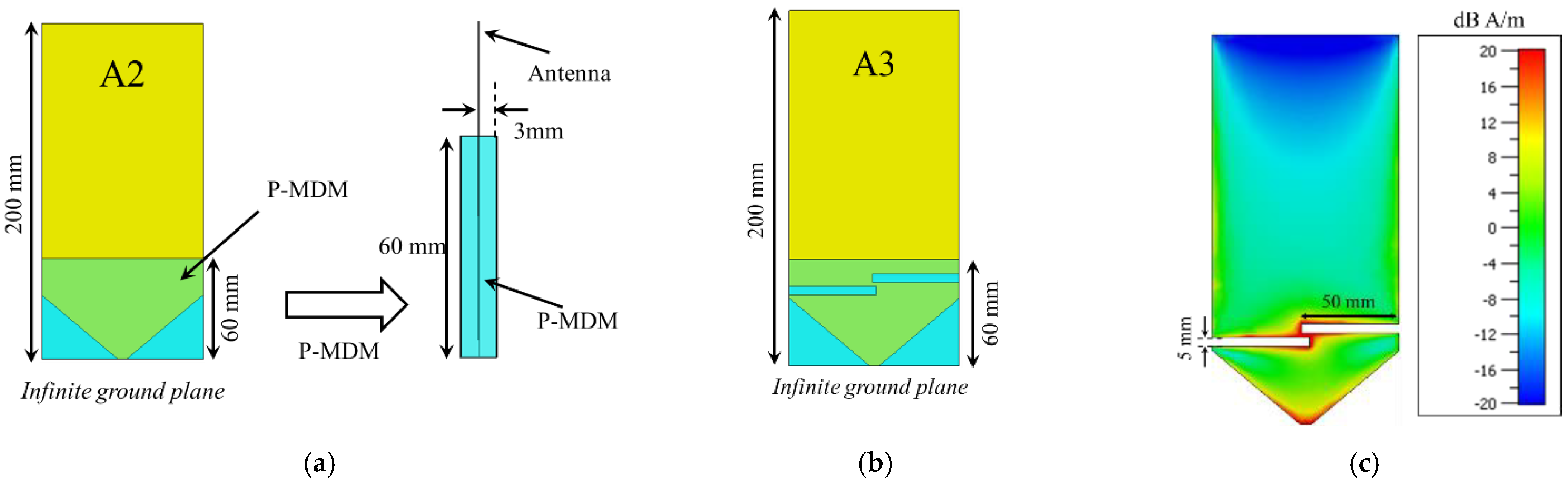
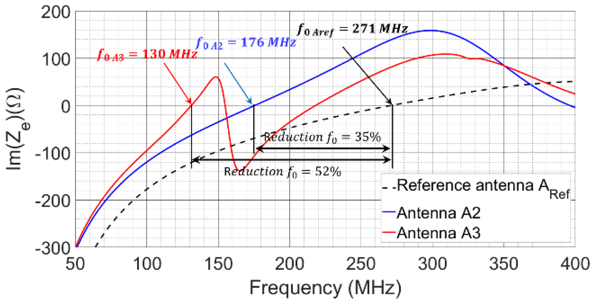
4. Miniaturization of the Monopole Antenna Using a P-MDM
5. Parametrical Study
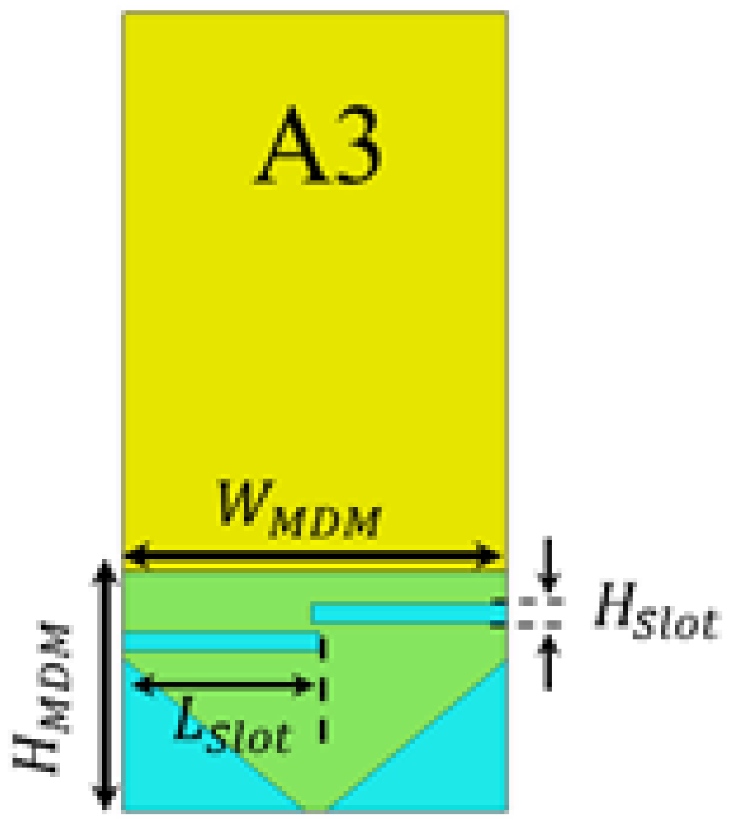
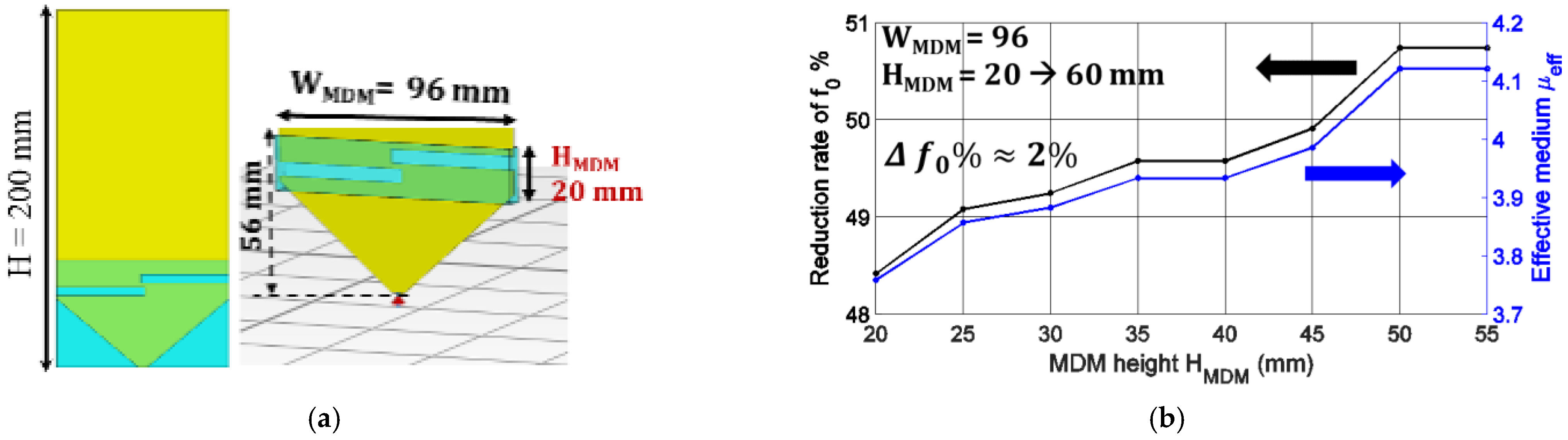
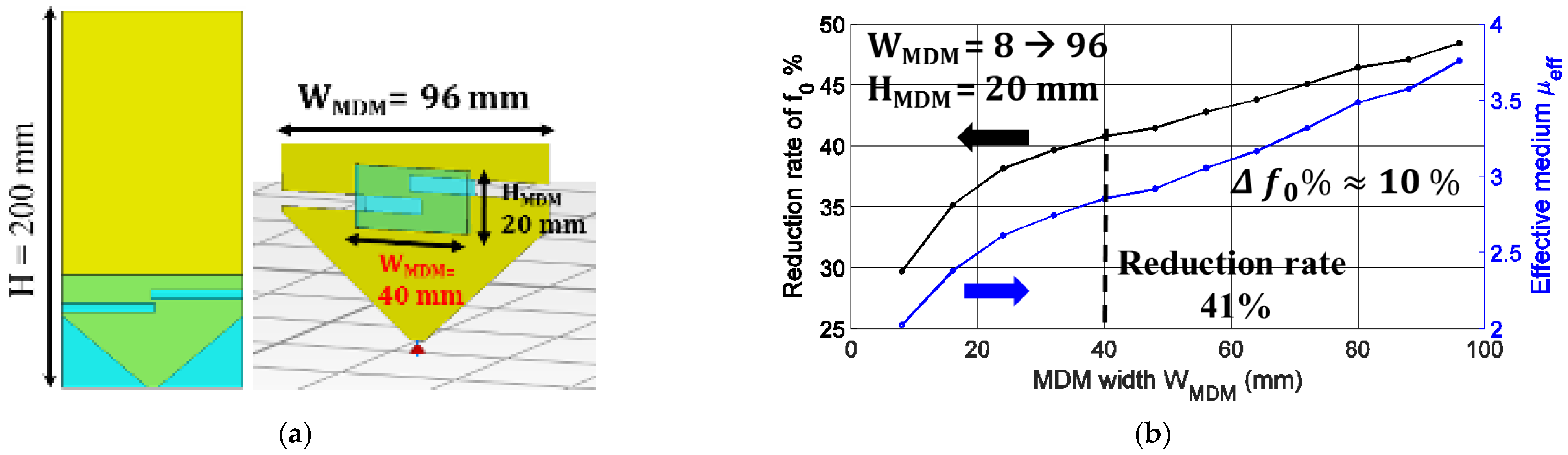
5.1. Optimization of the Position and the Dimensions of the P-MDM
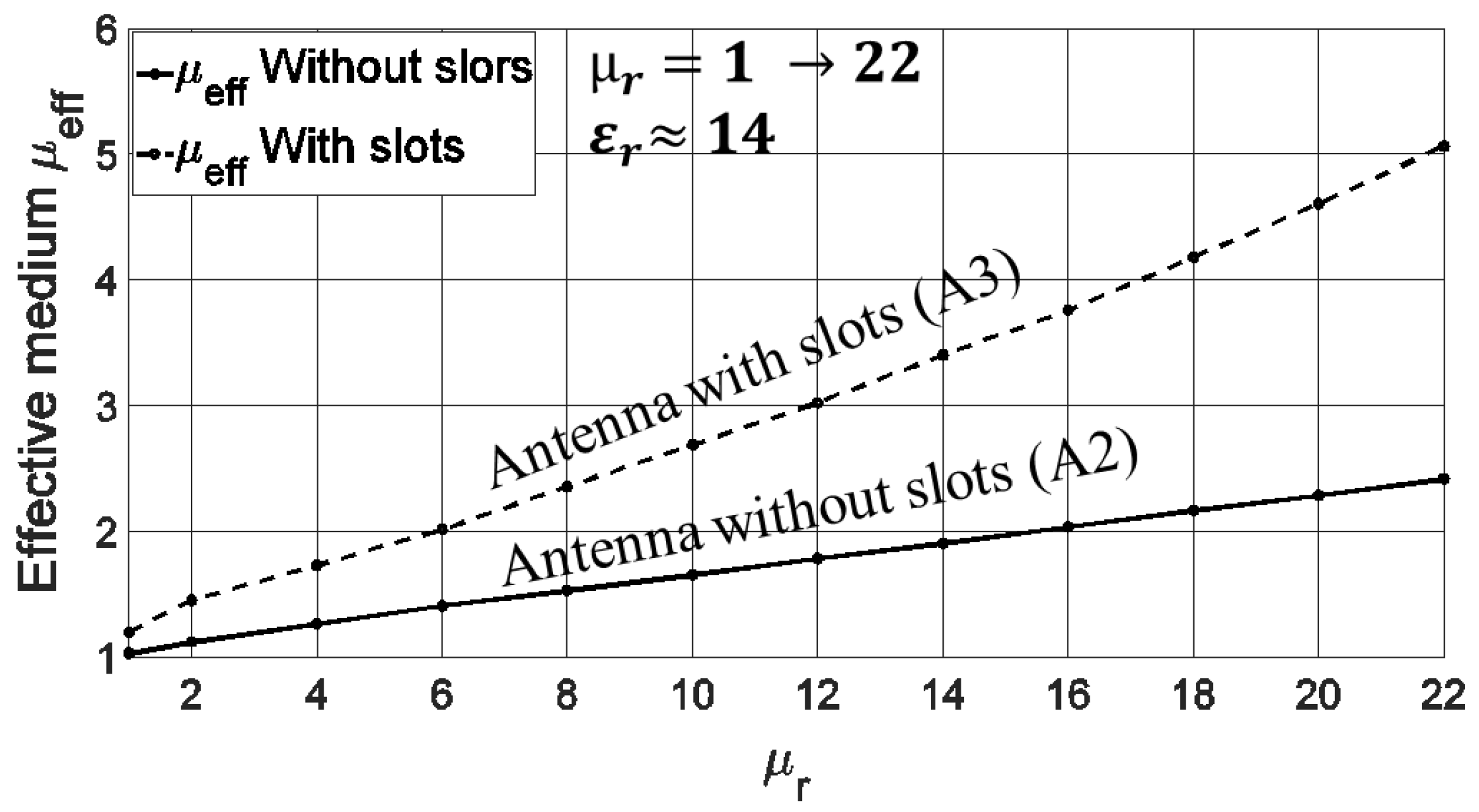
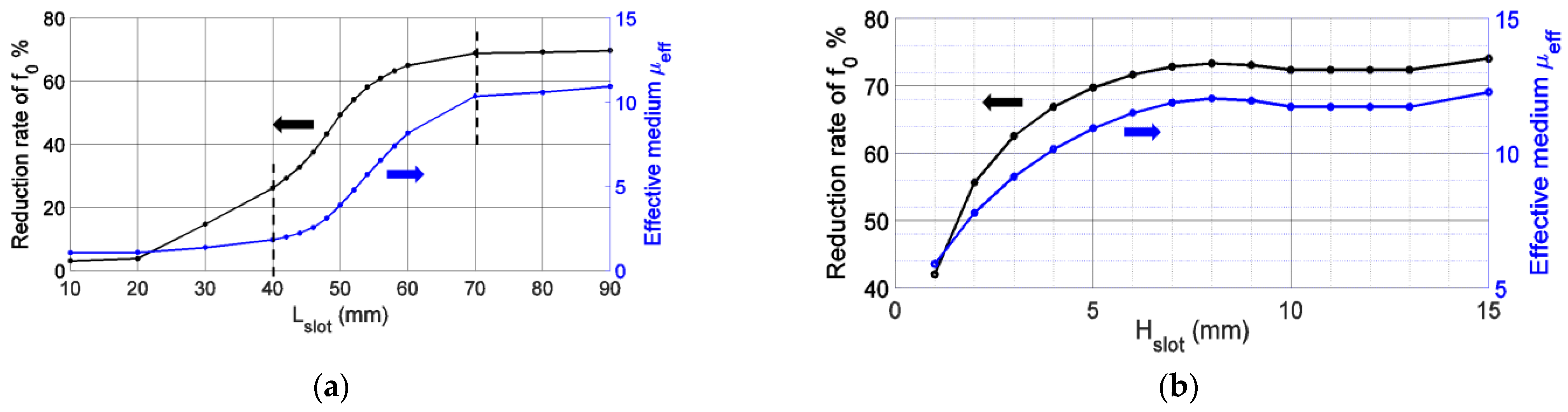
5.2. Slots Dimensions Effect on the Miniaturization Rate
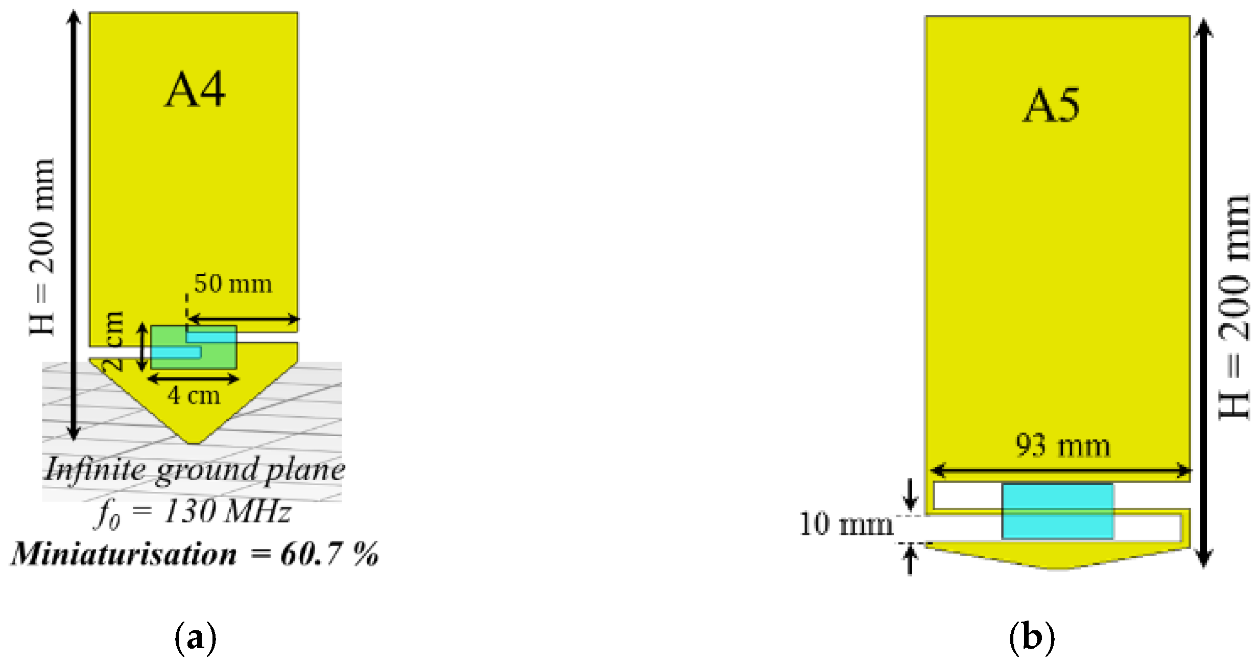
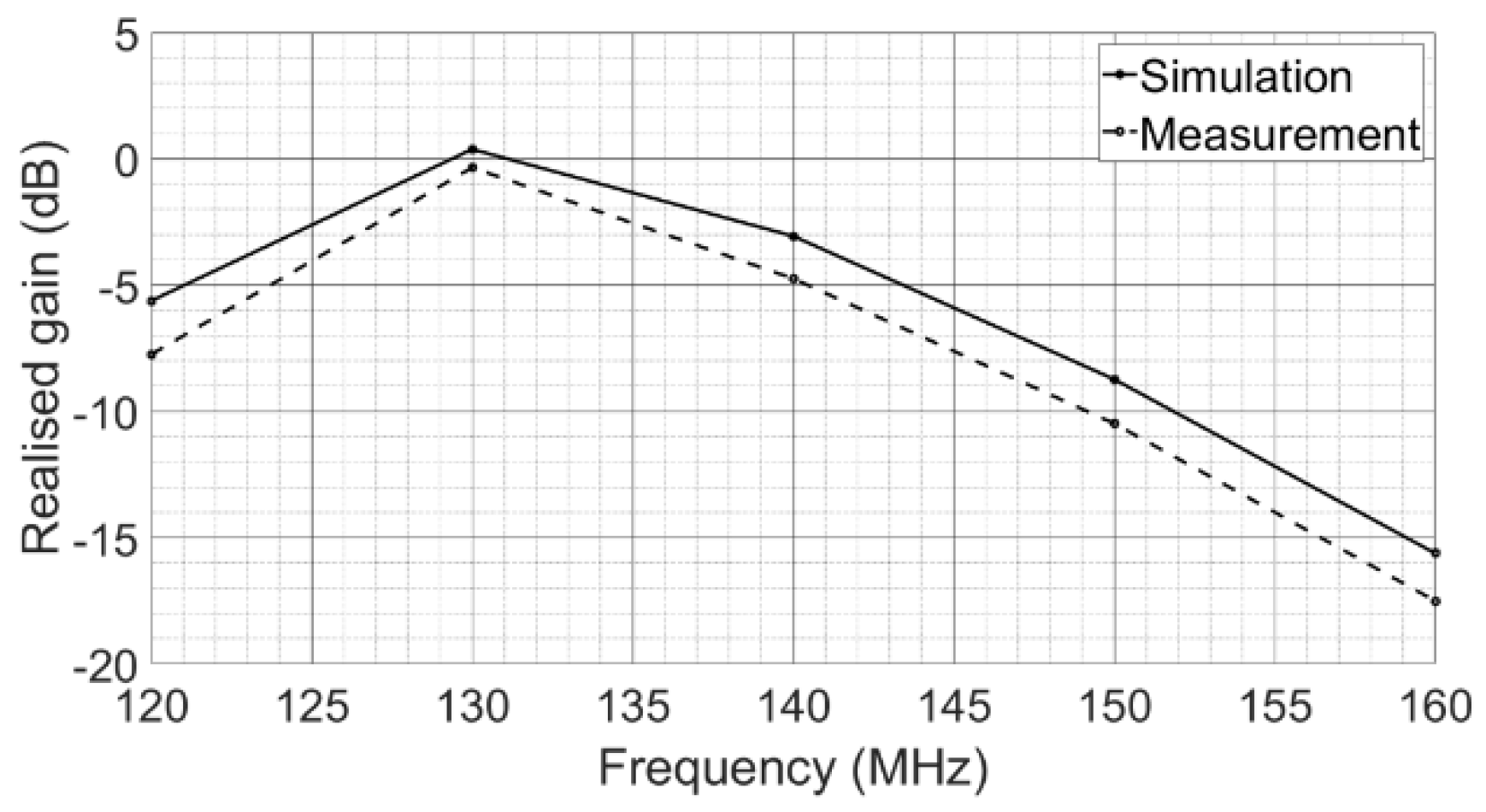
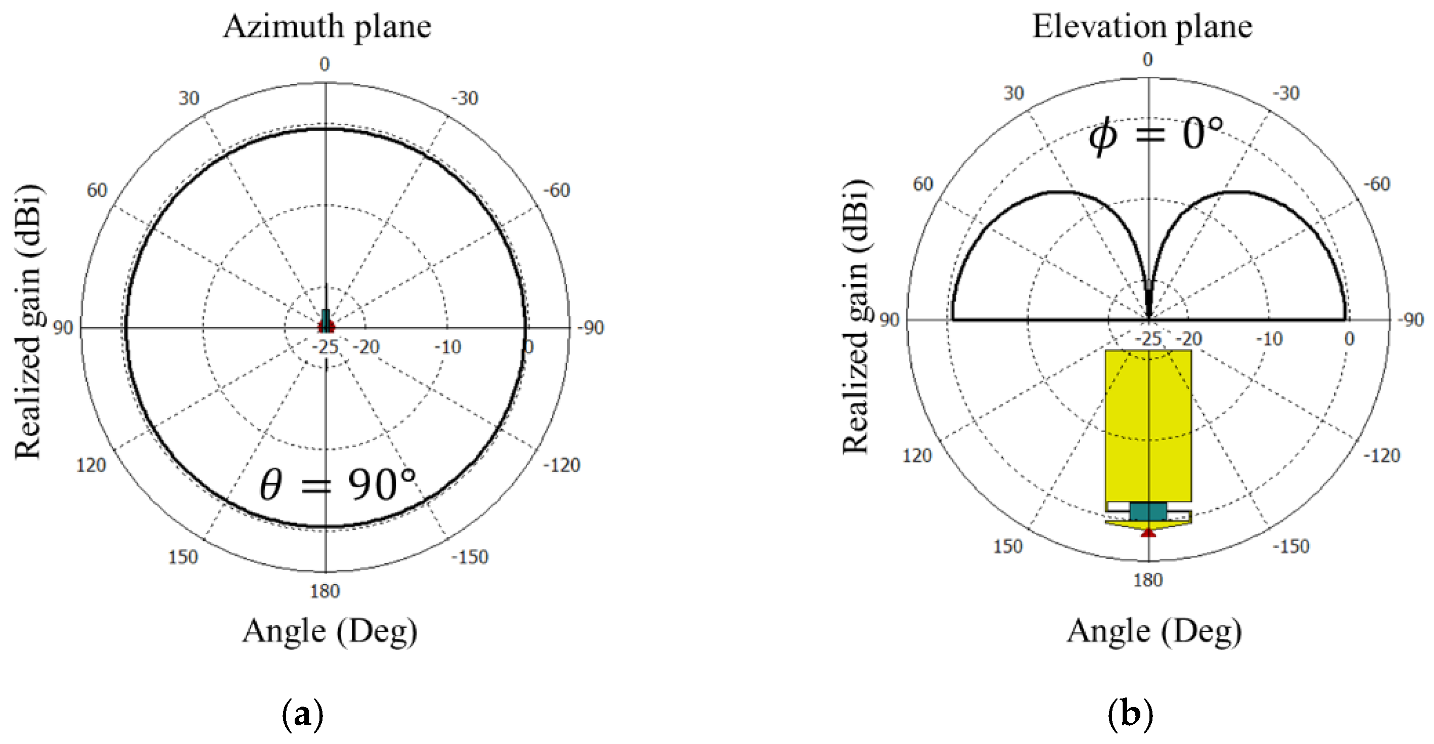
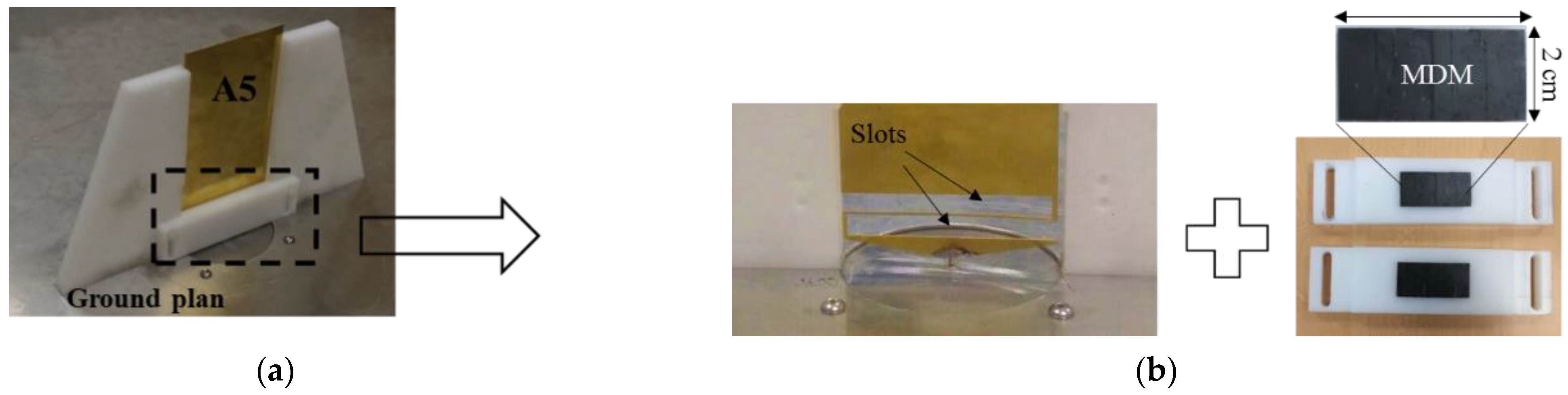
6. Realization and Experimental Validation
7. Conclusions
Author Contributions
Funding
Conflicts of Interest
References
- Sairam, C.; Khumanthem, T.; Ahirwar, S.; Singh, S. Broadband blade antenna for airborne applications. In Proceedings of the 2011 Annual IEEE India Conference, Hyderabad, India, 16–18 December 2011; pp. 3–6. [Google Scholar]
- Arand, B.A.; Shamsaee, R.; Yektakhah, B. Design and fabrication of a broadband blade monopole antenna operating in 30 MHz-600 MHz frequency band. In Proceedings of the 21st Iranian Conference on Electrical Engineering, ICEE, Mashhad, Iran, 14–16 May 2013; pp. 1–3. [Google Scholar]
- Ahirwar, S.D.; Sairam, C.; Kumar, A. Broadband blade monopole antenna covering 100–2000 MHz frequency band. In Proceedings of the 2009 Applied Electromagnetics Conference (AEMC), Kolkata, India, 14–16 December 2009; pp. 1–4. [Google Scholar]
- Rhee, C.Y.; Kim, J.H.; Jung, W.J.; Park, T.; Lee, B.; Jung, C.W. Frequency-reconfigurable antenna for broadband airborne applications. IEEE Antennas Wirel. Propag. Lett. 2014, 13, 189–192. [Google Scholar] [CrossRef]
- Mattei, J.-L.; le Guen, E.; Chevalier, A. Dense and half-dense NiZnCo ferrite ceramics: Their respective relevance for antenna downsizing, according to their dielectric and magnetic properties at microwave frequencies. J. Appl. Phys. 2015, 117, 084904. [Google Scholar] [CrossRef]
- Hwang, Y.; Zhang, Y.P.; Zheng, G.X.; Lo, T.K.C. Planar inverted F antenna loaded with high permittivity material. Electron. Lett. 1995, 31, 1710–1712. [Google Scholar] [CrossRef]
- Ittibipoon, A.; Mongia, R.K.; Cuhaci, M. Low profile dielectric resonator antennas using a very high permittivity material. Electron. Lett. 1994, 30, 1362–1363. [Google Scholar]
- Hansen, R.C.; Burke, M. Antennas with magneto-dielectrics. Microw. Opt. Technol. Lett. 2000, 26, 75–78. [Google Scholar] [CrossRef]
- Erkmen, F.; Chen, C.C.; Volakis, J.L. UWB magneto-dielectric ground plane for low-profile antenna applications. IEEE Antennas Propag. Mag. 2008, 50, 211–216. [Google Scholar] [CrossRef]
- Rozanov, K.N.; Ikonen, P.M.T.; Tretyakov, S.A.; Osipov, A.V.; Alitalo, P. Magnetodielectric Substrates in Antenna Miniaturization: Potential and Limitations. IEEE Trans. Antennas Propag. 2006, 54, 3391–3399. [Google Scholar]
- Mosallaei, H.; Sarabandi, K. Magneto-Dielectrics in Electromagnetics: Concepts and Applications. IEEE Trans. Antennas Propag. 2004, 52, 1558–1567. [Google Scholar] [CrossRef] [Green Version]
- Niamien, M.A.C.; Collardey, S.; Sharaiha, A.; Mahdjoubi, K. Printed inverted-F antennas over lossy magneto-dielectric materials: Theoretical approach and validations. IET Microw. Antennas Propag. 2014, 8, 513–522. [Google Scholar] [CrossRef]
- Li, Q.; Chen, Y.; Yu, C.; Young, L.; Spector, J.; Harris, V.G. Emerging magnetodielectric materials for 5G communications: 18H hexaferrites. Acta Mater. 2022, 231, 117854. [Google Scholar] [CrossRef]
- Zaid, J.; Farahani, M.; Denidni, T.A. Magneto-dielectric substrate-based microstrip antenna for RFID applications. IET Microw. Antennas Propag. 2017, 11, 1389–1392. [Google Scholar] [CrossRef]
- Lee, J.; Heo, J.; Lee, J.; Han, Y. Design of small antennas for mobile handsets using magneto-dielectric material. IEEE Trans. Antennas Propag. 2012, 60, 2080–2084. [Google Scholar] [CrossRef]
- Karilainen, A.O.; Ikonen, P.M.T.; Simovski, C.; Tretyakov, S.A.; Lagarkov, A.N.; Maklakov, A.; Rozanov, K.N.; Starostenko, S.N. Experimental studies on antenna miniaturisation using magneto-dielectric and dielectric materials. IET Microw. Antennas Propag. 2011, 5, 495. [Google Scholar] [CrossRef] [Green Version]
- Kabalan, A.; Tarot, A.-C.; Sharaiha, A. Miniaturization of a broadband monopole antenna using low loss magneto-dielectric materials in VHF band. In Proceedings of the Loughborough Antennas & Propagation Conference, Loughborough, UK, 13–14 November 2017. [Google Scholar]
- Ramahi, O.M.; Mittra, R. Design of a Matching Network for an HF Antenna Using the Real Frequency Method. IEEE Trans. Antennas Propag. 1989, 37, 506–509. [Google Scholar] [CrossRef]
- Murata Manufacturing Co., Ltd. Available online: https://www.murata.com/ (accessed on 21 June 2018).


Publisher’s Note: MDPI stays neutral with regard to jurisdictional claims in published maps and institutional affiliations. |
© 2022 by the authors. Licensee MDPI, Basel, Switzerland. This article is an open access article distributed under the terms and conditions of the Creative Commons Attribution (CC BY) license (https://creativecommons.org/licenses/by/4.0/).
Share and Cite
Kabalan, A.; Sharaiha, A.; Tarot, A.-C. Electrically Small Wideband Monopole Antenna Partially Loaded with Low Loss Magneto-Dielectric Material. Magnetism 2022, 2, 229-238. https://doi.org/10.3390/magnetism2030017
Kabalan A, Sharaiha A, Tarot A-C. Electrically Small Wideband Monopole Antenna Partially Loaded with Low Loss Magneto-Dielectric Material. Magnetism. 2022; 2(3):229-238. https://doi.org/10.3390/magnetism2030017
Chicago/Turabian StyleKabalan, Aladdin, Ala Sharaiha, and Anne-Claude Tarot. 2022. "Electrically Small Wideband Monopole Antenna Partially Loaded with Low Loss Magneto-Dielectric Material" Magnetism 2, no. 3: 229-238. https://doi.org/10.3390/magnetism2030017
APA StyleKabalan, A., Sharaiha, A., & Tarot, A.-C. (2022). Electrically Small Wideband Monopole Antenna Partially Loaded with Low Loss Magneto-Dielectric Material. Magnetism, 2(3), 229-238. https://doi.org/10.3390/magnetism2030017