1. Introduction
The synthesis and intensification of chemical processes have been widely researched, with distillation structures and their connectivity being given in advance using optimization algorithms based on mathematical programming or stochastic optimization. For example, heat integration in intensified distillation in order to separate multicomponent mixtures [
1], reactive distillation [
2,
3], and membrane-assisted distillation [
4], among other distillation-based intensified processes, have been considered. Previous works used superstructure representations comprising several unit operations such as distillation columns, heat exchangers, decanters, or membranes. A superstructure is a representation in which all possible interconnections among process units are included; this development has been a significant breakthrough in process synthesis, design, and optimization, because it has made it possible to depart from experience-based heuristics and thermodynamic approaches, and propose more systematic ways to assess any possible flowsheet alternatives simultaneously [
5]. Nevertheless, there is an intrinsic limitation when superstructures are composed of unit operations [
6]. Thus, one way to overcome this limitation is to depart from the idea of unit operations and synthesize processes based on phenomenological approaches.
Several process synthesis and intensification approaches based on phenomenological analysis have been proposed over the last few decades. This section summarizes the achievements of several research groups, and the next section addresses our PS+I framework in detail.
Gani and coworkers have proposed a phenomena-based process synthesis method consisting of phenomena building blocks (PBBs). This methodology presents systematic identification, generation, and screening of phenomena-based flowsheet options. It was applied for the reactive distillation process to produce isopropyl acetate from acetic acid and isopropanol, and the solution achieved a 99% conversion of isopropanol, with energy requirements 90% less than those of the conventional process [
7]. This combined intensification–synthesis methodology was applied to produce methyl acetate through a membrane-assisted process [
8]. Kongpanna et al. proposed a PBB framework for dimethyl carbonate production with CO
2 utilization consisting of three stages: synthesis, design, and innovation. The proposed processes included process intensification alternatives such as membrane-assisted and reactive distillation and membrane reactors [
9]. Garg et al. generated innovative and sustainable designs of chemical and biochemical processes using the PBB framework in which intensified processes such as reactive distillation, divided-wall distillation, crystallization-membrane, distillation-membrane, etc. attained savings of more than 20% in economic and environmental contexts, compared to the conventional cases [
10]. The PBBs were represented in a superstructure model for a reactor network comprising arbitrary combinations of non-isothermal reactor models. The transesterification of propylene carbonate with methanol was taken as a case study, and the results prove the benefits of the proposed method over predefined unit operations [
11]. In a recent work, Garg et al. summarize the most relevant works using the PBB framework to generate novel and intensified processes [
12].
Papalexandri and Pistikopoulos proposed the Generalized Modular Representation Framework (GMF) for process synthesis [
13]. They proposed multipurpose mass and heat-transfer modules as the framework’s building blocks, as represented by a superstructure. This framework was applied for acetone recovery, benzene alkylation, ethylene glycol production, and heat integration. The GMF was applied for the separation of a benzene/toluene/o-xylene mixture based on aggregated physical models comprised by a superstructure, which then were reformulated as a mixed-integer nonlinear programming (MINLP) problem. The most energy-efficient distillation column sequence was the Petlyuk column, attaining 30% energy savings [
14]. Later, the GMF was applied to synthesize a NOx reactive absorption process, obtaining the most economical design, meeting the design targets, and leading to economic and environmental benefits [
15]. The GMF has also been applied to the water/ethanol extractive distillation process, in which the entrainer selection, synthesis, and intensification were considered in a single mixed-integer nonlinear optimization (MINLP). The optimal result from the synthesis problem was validated through process simulation in Aspen Plus [
16]. Later, a multiperiod GMF was proposed to ensure that the designs could be operated under specified ranges of uncertain parameters to produce methyl tert-butyl ether. Also, risk assessment, accounting for equipment failure frequency and consequence severity, was incorporated into the synthesis problem to derive inherently safer designs, which were validated through process simulation [
17].
Hasan and coworkers proposed a block-based superstructure of blocks arranged in a two-dimensional grid as an alternative method for synthesizing chemical processes. The synthesis problem was reformulated as an MINLP problem for the purposes of generating automated flowsheets and their optimization. Three reactor/separator systems were studied to validate the proposed method. The first case study investigates the hydrodealkylation of the toluene process used to produce benzene, and the second one involves four components: A and B are used as raw materials to produce C, which reacts further in a second reaction to obtain the final product, D. Thus, five separations and three reaction alternatives are available. The third case is the reaction of methane and CO
2 to produce value-added products, such as methanol. In all cases, the resulting processes were intensified and showed a better performance in terms of energy consumption and cost. Nevertheless, solving MILP problems and reducing the feasible region posed difficulties [
18]. A later work proposed a Process Synthesis, Integration, and Intensification approach to produce ethylene glycol by reacting ethylene oxide and water, although a further reaction between the ethylene oxide and ethylene glycol produces diethylene glycol. The intensified solution was a reactive distillation producing mainly ethylene glycol and some diethylene glycol. However, these components were separated in a distillation column [
19]. The same method was extended for synthesizing and intensifying membrane separations, such as separating nitrogen from methane to produce fuel-grade methane or in the methanol/water separation through vapor permeation. In both cases, membrane-based processes can offer significant benefits in terms of economics and sustainability, and they are potential alternatives which could replace conventional energy-intensive adsorption and distillation-based processes [
20].
Manousiouthakis and coworkers proposed an Infinite Dimensional State-Space (IDEAS) framework for synthesizing chemical processes. The IDEAS process representation considers all possible connections among a network of unit operations, and it can solve a convex problem because it can be solved as a linear programming (LP) problem. Thus, due to their great network flexibility, the optimal solutions often include nonintuitive and counterintuitive process units [
21]. This approach has been applied to synthesize multi-pressure distillation of homogeneous azeotropic mixtures [
22] and to intensify reactive separator networks [
23].
Hasebe and coworkers have extended the IDEAS framework to the separation of binary [
24] and ternary [
25] mixtures, including two important features: (1) relaxation of liquid compositions and (2) solution interpretation to obtain intensified and realistic distillation processes. This approach has been applied for synthesizing and intensifying reactive distillation processes [
26] and separating heterogeneous azeotropes [
27].
Our proposed Process Synthesis and Intensification (PS+I) framework is a further extension of the IDEAS framework and a continuation of the latest works from Hasebe and coworkers. The PS+I framework takes advantage of the following key novelties: (1) it departs from the unit operation concept, and instead, it connects “functional modules” as building blocks that represent physical and chemical phenomena resulting in intensified processes; (2) the synthesis problem is solved without any a priori knowledge or preset connectivity among equipment; and (3) although the synthesis problem solution will result in an unknown process structure, after interpretation, it is known and post-optimized. Thus, the resulting process is intensified.
In our approach, we have formulated the synthesis problems as LP problems and as mixed-integer linear programming (MILP) problems, while other approaches, such as the PPB and GMF, have used nonlinear programming (NLP) and mixed-integer nonlinear programming (MINLP). In our proposed framework, intensive properties (e.g., composition, and molar enthalpy) are input as parameters in the optimization problem, and the optimization variables are extensive properties (e.g., mass and energy flows).
The original aspect and main contribution of this entry is the description of the synthesis and intensification of distillation-based processes using preestablished information relating to the distillation process structure, which means that their connections are not needed. Thus, it does not consider any structural assumption, which is why the proposed approach can derive novel, counterintuitive distillation structures. For example, a combination of conventional distillation columns will never result in a Petlyuk column. In addition, the mathematical formulation is relatively simple and compact, yet powerful enough to solve even millions of equations. Also, the post-optimization step helps to refine the solution obtained from solving the synthesis problem.
2. Low-Aggregation Superstructure
Since the synthesis problem starts at one level down from the unit operation level, it considers the core process phenomena. Therefore, the synthesis problem is represented by a low-aggregation superstructure.
Figure 1 shows a distillation module, which is equal to a distillation stage where vapor and liquid reach equilibrium by coming into contact with each other. Each uniquely defined subspace is assigned to a distillation module by discretizing the liquid composition space in a mixture. The proposed framework assumes that a vapor–liquid equilibrium is attained in each module. Additionally, since the liquid composition, pressure, and thermodynamic state (i.e., saturated liquid) are known in advance for each subspace, the molar enthalpy and the vapor composition in each phase are uniquely defined.
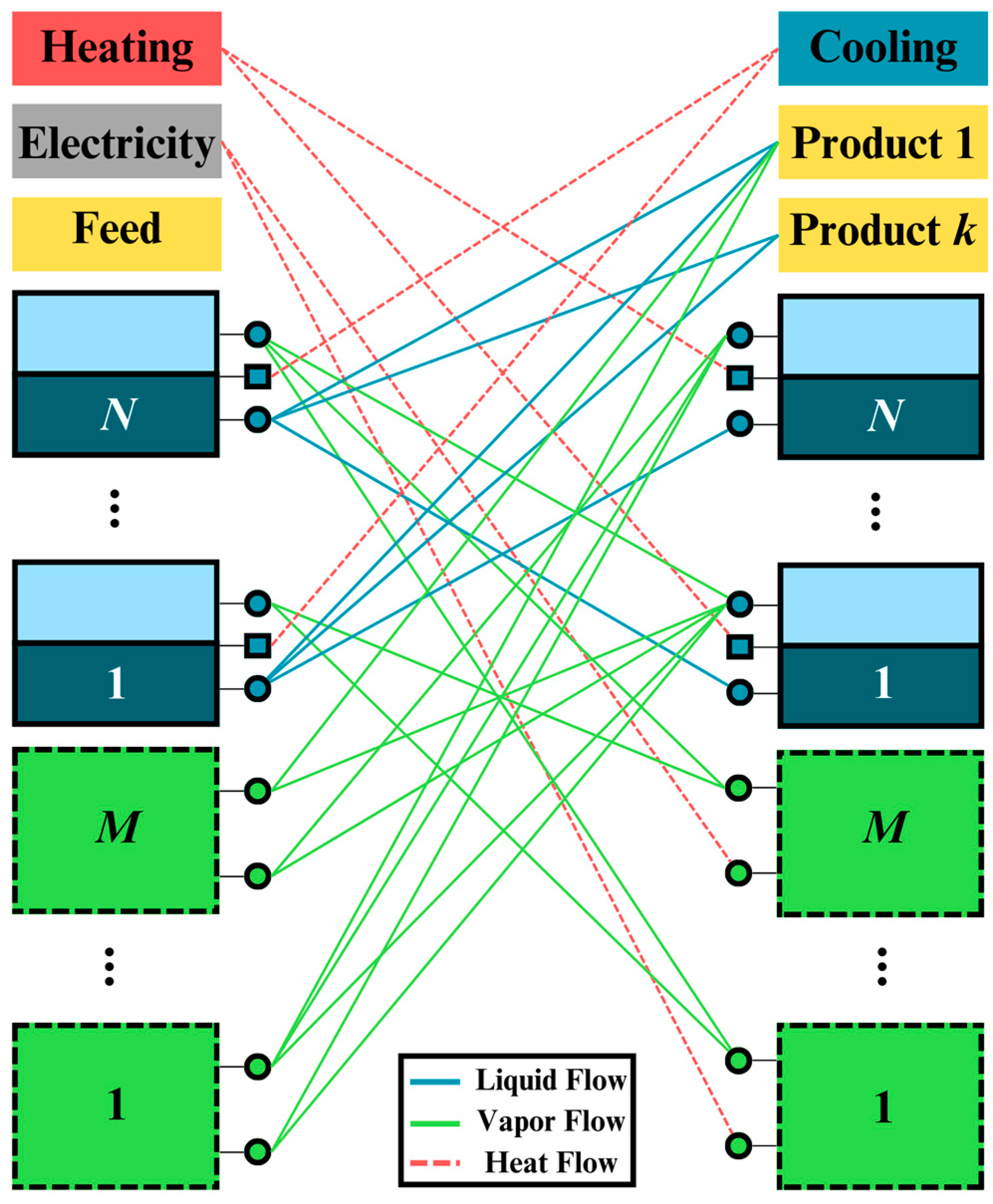
Figure 2 shows the superstructure’s conceptual representation of the synthesis problem.
The solid squares from 1 to cap
N represent distillation modules, and the dashed squares from 1 to
are other types of modules (i.e., decanter modules and membrane modules). Previously, we have applied the
PS+I framework, using only distillation modules, for the separation of ternary mixtures [
28], homogeneous azeotropic mixtures [
29], and heterogeneous azeotropic mixtures, without using decanters [
27]. Other modules included in the superstructure are decanter modules [
30] and membrane modules [
31]. Thus, we can add as many modules as possible to represent several phenomena. The mass and energy flows between modules will determine the optimal structure. Therefore, giving or assuming any structure in advance is unnecessary.
Each separation module can be divided into two parts: outlet and inlet. It is worth mentioning that two squares of the same number correspond to the same module. The solid lines and dashed lines among the modules are the liquid, vapor, heat, and electricity flow connections.
The feed, products, electricity, heating, and cooling utilities are treated in a special manner. The feed, electricity, and heating utilities have only outlet flows, while the products and cooling utilities have only inlet flows. Thus, optimal liquid and vapor flow paths between modules will result in the optimal process structure.
The synthesis problem is reformulated as an LP problem [
28] or MILP programming [
31]. The objective function minimizes utility costs (e.g., heating, cooling, and electricity). Nevertheless, other objective functions, such as energy minimization or profit maximization, can be implemented in the proposed framework if linear functions represent the objective function. Also, the synthesis problem can be solved for any number of components. However, it has been applied to separate binary and ternary mixtures because the graphical representation of solutions is easy to understand and interpret.
The graphical representation allows for the interpretation and translation of the mathematical solution into a task-integrated realistic process. Finally, the interpreted solution is simulated, validated, and post-optimized.
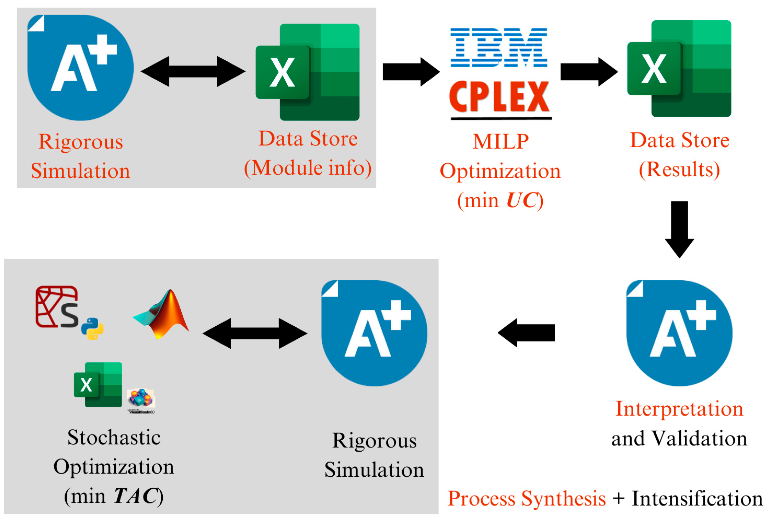
Figure 3 shows the steps in the
PS+I framework, and
Figure 4 shows how different software programs are integrated into the framework to find novel and intensified process structures.
As shown in
Figure 3, the proposed framework consists of the following five steps: (1) generation of a database, (2) optimization, (3) interpretation, (4) simulation and validation, and (5) post-optimization.
In
Figure 4, the top part shows the link between solving the synthesis problem and solution validation, the gray box shows the database generation, and the bottom part shows how the software is linked to solving the post-optimization problem.
2.1. Separation of a Ternary Mixture
The results for separating a ternary mixture composed of benzene/toluene and /o-xylene are presented in this section because this technique has been widely used to assess the effectiveness of synthesis problems. This problem has also been studied by Takase et al. [
25]. The key mathematical difference between this framework and our
PS+I framework is explained in detail in a previous work [
28].
As shown in
Figure 2, there are functional modules, which represent a given phenomenon (e.g., the vapor–liquid equilibrium), and lines, which represent energy and mass flows among modules. Thus, the mathematical formulation will basically contain an objective function, energy balances, mass balances, and purity constraints for products, since the feed composition and thermodynamic state are given in advance. By discretizing the liquid composition space, and assigning a functional module for each subspace, the component mass and energy balances can be fully linearized, since the liquid and vapor composition are uniquely defined for each functional module.
Figure 5a shows the discretized liquid composition space of a ternary diagram, which is a graphical representation for the separation of a ternary mixture, and
Figure 5b shows four discretized composition subspaces in a dashed red square on the ternary diagram.
If a ternary space is discretized in an infinite number of subspaces, and thus an infinite number of distillation modules, the mathematical problem will result in an infinite linear programming (ILP) problem, and the exact solution covering the entire liquid composition space will be obtained. However, since the synthesis problem must be solved within a finite number of modules, and a relaxation in the model must be added to cover the distillation modules that are not explicitly included in the synthesis problem.
Figure 5a shows the liquid and vapor composition vectors, respectively. Thus, Takase and Hasebe have relaxed the upper and limit bound of the liquid composition of the light (
,
) and heavy (
,
) key components in the composition vector
at each module
. However, in the proposed
PS+I framework, another approach has been taken: “Instead of relaxing liquid compositions, the material and energy balances have been relaxed.” Therefore, the material and energy balances must be within a given tolerance error
.
Taking the component material balance in each module
, Equation (1) shows the relaxation proposed by Takase and Hasebe [
25]. In contrast, Equation (2) shows the relaxation proposed in the
PS+I framework [
28].
where
and
are the liquid and vapor flows between modules
and
,
is the liquid flow from the feed to module
, and
is the liquid flowrate from module
to product
.
and
are liquid and vapor compositions in module
, which are input as parameters because they are known in advance when the composition space is discretized.
and
are the sets of distillation modules and product modules, respectively. Finally,
is the minimum tolerance error needed to obtain a mathematically feasible solution. However, the solution for
results in large values for
and
(i.e., minimum reflux condition). Therefore,
is required to attain a feasible and realistic solution.
The synthesis problems proposed by Takase and Hasebe [
25] and Alcántara Avila et al. [
28] attained the same optimal distillation structure, which was interpreted as the Petlyuk column. Here, it is worth mentioning that there are only two sequences of conventional distillation column used for the separation of a ternary mixture (i.e., direct and indirect sequences). However, the novelty of the proposed
PS+I is that the Petlyuk column was derived without any preestablished structural assumptions.
The proposed
PS+I framework obtained the optimal solution with less computation time and fewer distillation modules, compared to the work from Takase and Hasebe [
25]. Therefore, the presented relaxation is more effective in solving the synthesis problem. In addition, the post-optimization step makes it possible to rearrange the Petlyuk column as a Dividing Wall Column (DWC). In this work, the synthesis problem minimizes the utility cost because distillation is largely dominated by this cost. Therefore, the solutions tend to interconnect many modules (i.e., equilibrium stages). Nevertheless, the post-optimization results show a better balance between energy consumption and equipment cost because both costs are explicitly considered in the objective function shown in Equation (3), which is the
minimization.
where
is the cost of utilities such as steam or cooling water.
is the cost of every
equipment presents in the scheme, such as the plates, the process vessel, heat exchangers, etc. The latter is divided over a payback time to annualize the cost; usually a payback time from 3 to 10 years is taken, this depends on the size and type of the process.
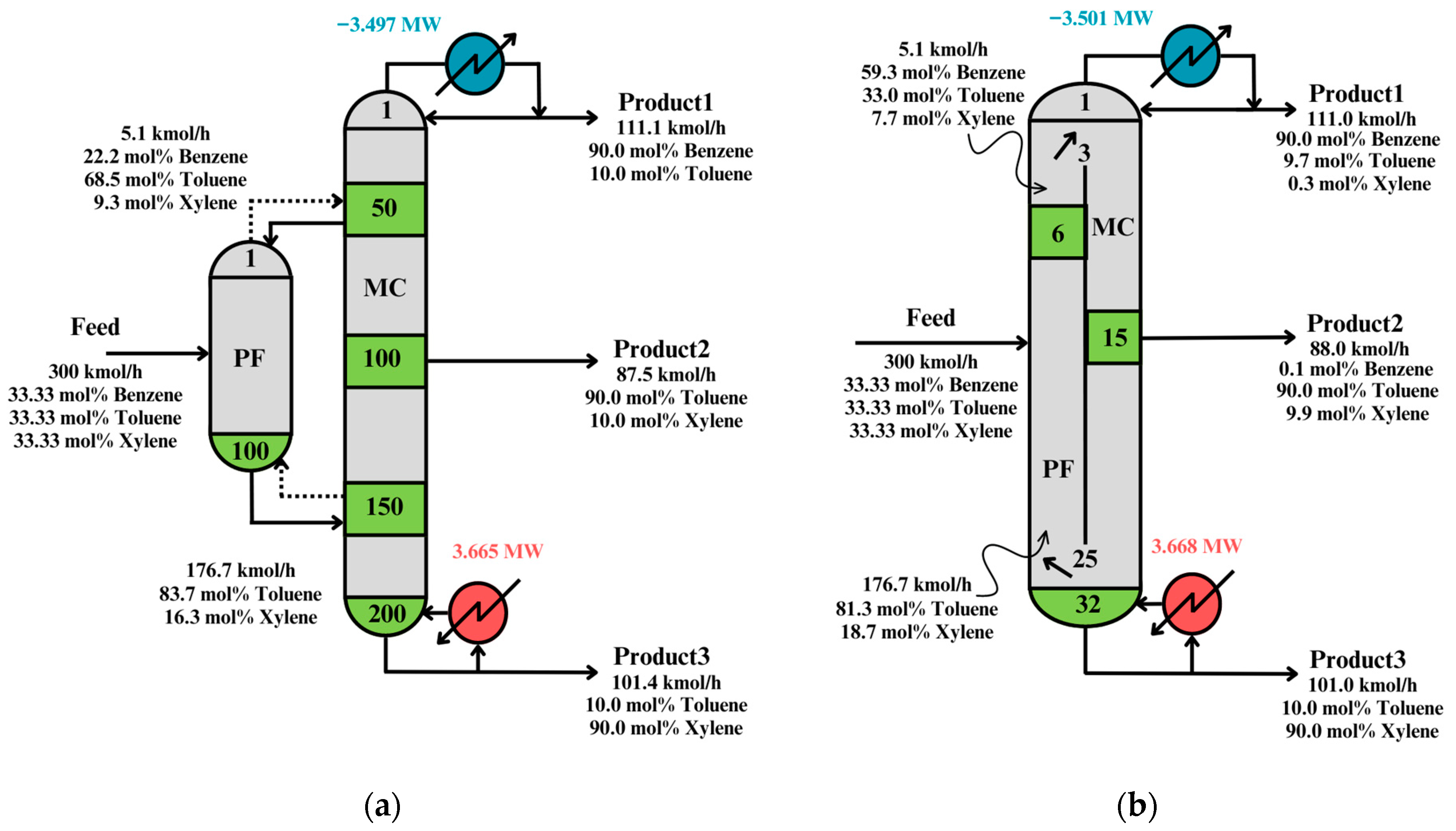
Figure 6 shows the solution after interpretation and validation, and the solution at post-optimization.
Table 1 shows the problem feed data, desired purities, and additional information.
As can be seen in
Figure 6a, the interpreted solution has many stages, because the synthesis problem minimizes the utility cost. Thus, the optimal solution will tend to the minimum reflux condition (i.e., many stages).
Figure 6b shows the post-optimized solution when the Total Annual Cost (TAC) is minimized. Therefore, it has fewer stages than the solution in
Figure 6a. It is important to notice that the energy consumption in both cases is similar, which proves the technique’s effectiveness in solving the synthesis problem.
Table 3 shows a comparison between the solutions in
Figure 6 to show how the distillation structure was improved.
The TAC was improved by 0.585 M$/year and the energy cost obtained a minimum increase of 0.003 MW in the post-optimization. This means the post-optimization step can greatly reduce the equipment cost without affecting the energy consumption cost, because the latter one is already optimized at the synthesis step.
2.2. Heterogeneous Azeotropic Distillation
Heterogeneous azeotropic distillation is widely used in the chemical industry to separate mixtures containing at least one azeotrope. The addition of a third component creates new azeotropes and two liquid phases. Thus, heterogeneous azeotropic distillation is commonly used due to the ease of recovery of the entrainer and the transition across a distillation boundary in a decanter. In this section, the ethanol/water separation using benzene as an entrainer was considered as a case study [
32].
In the superstructure shown in
Figure 2, the dashed squares can represent decanter modules.
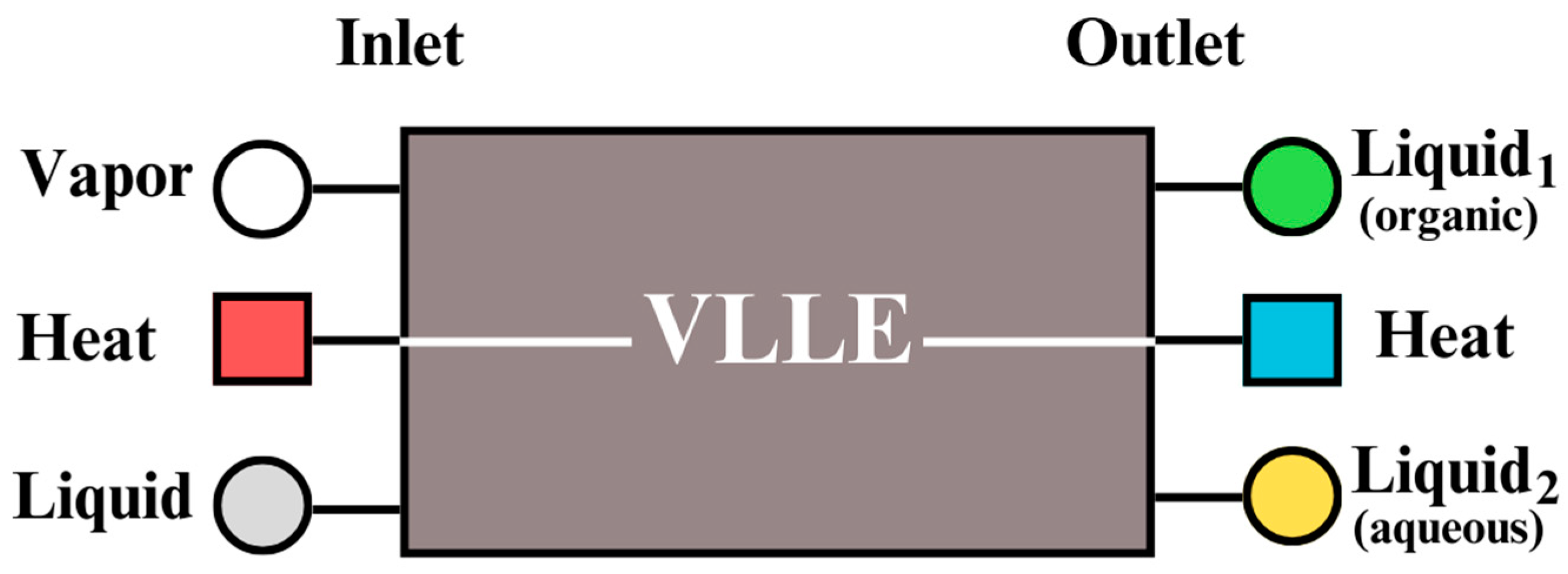
Figure 7 shows the conceptual representation of a decanter module where Vapor–Liquid–Liquid Equilibrium (VLLE) takes place.
Liquid and vapor flows can enter the module, and two liquids in different phases leave the module. Also, the heat inlet and outlet are used to satisfy the energy balance. A decanter module is equivalent to a decanter equipment. Therefore, a tie line represents a decanter module. The superstructure considering distillation and decanter modules is reformulated as an LP problem.
Table 4 shows the problem feed data, desired purities, and additional information for this section’s problem.
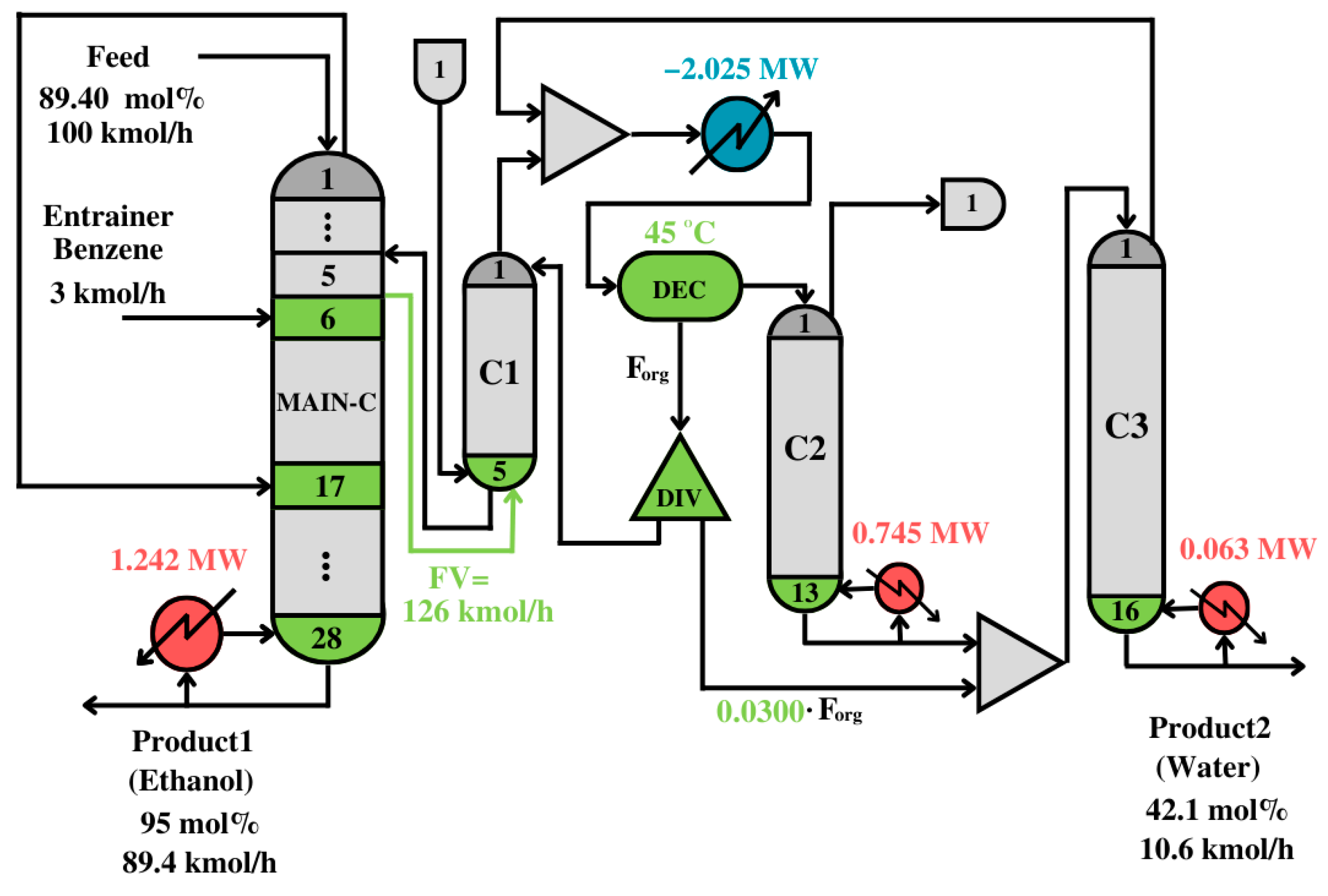
Figure 8 shows the process structure after the solution and the interpretation of the solution for the synthesis problem.
As can be seen in
Figure 8, the interpreted solution is an intensified distillation structure with a side rectifier. One of the most important and counterintuitive features is that the top vapor of the first column is recycled to the middle to promote ethanol separation, leaving the column at the bottom. The decanter separates the organic phase and recycles it to the first distillation column. The aqueous phase is fed to the distillation column C2. In C2 and C3, water concentrates, so it can accumulate at the bottom of the last column. The solution in
Figure 8 is post-optimized to find a better balance between energy and equipment costs by minimizing the TAC.
Figure 9 shows the post-optimized solution.
A modified Simulated Annealing Algorithm (m-SAA) was implemented to find the solution with the lowest TAC. The main improvements of the process are: (1) the decanter temperature increases to acquire a higher driving force to separate the components in organic and aqueous phases, and (2) interconnection and internal flows are smaller, which means smaller equipment and less energy consumption.
Table 6 shows the effectiveness of the
PS+I in finding solutions that are even better than previous methods which only solve the synthesis problem or only make an interpretation. The TAC was improved by 0.11 M
$/year and energy was reduced by 0.584 MW. In this case, the separation between the aqueous and organic phases is enhanced by optimizing the decanted temperature.
The solutions in
Figure 8 and
Figure 9 are counterintuitive because, typically, in conventional processes, the top vapor in the first column goes to the decanter, and it never is recycled to the same column. The presented solutions are against common practice and experience, yet they have much lower cost and energy consumption levels than shown in the conventional processes presented by Richardson et al. [
33], and consisting of three conventional columns and a decanter. The heat duty of the conventional process was 5.985 MW, which is almost twice the heat duty of the solution in
Figure 9.
2.3. Membrane-Assisted Separation Process
Membrane-assisted distillation is an alternative used to separate mixtures containing one homogeneous azeotrope. The separation is performed in this case because the sizes of the molecules are different. In this section, the ethanol/water separation is performed using a hydrophilic membrane made of polyvinyl alcohol (PVA), and it is also assumed that the membranes are replaced once a year [
31].
In the superstructure shown in
Figure 2, the dashed squares can represent membrane modules.
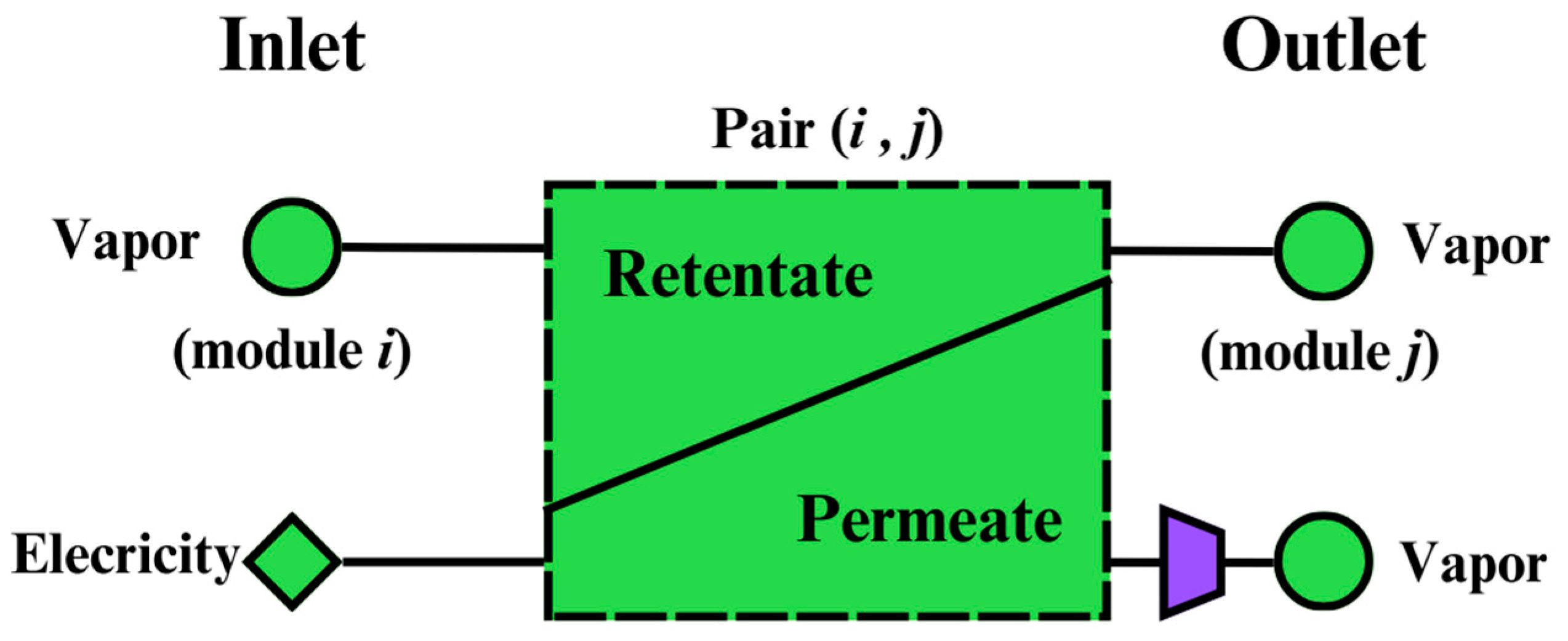
Figure 10 shows the conceptual representation of a membrane module in which the feed is separated into permeate and retentate streams. The membrane feed comes from the vapor leaving the distillation modules
. The retentate can enter to any module
where
, and the permeate can enter any modules other than
and
, or it can enter the product stream.
Table 7 shows the problem feed data, desired purities, and additional information for this section’s problem.
The squares in
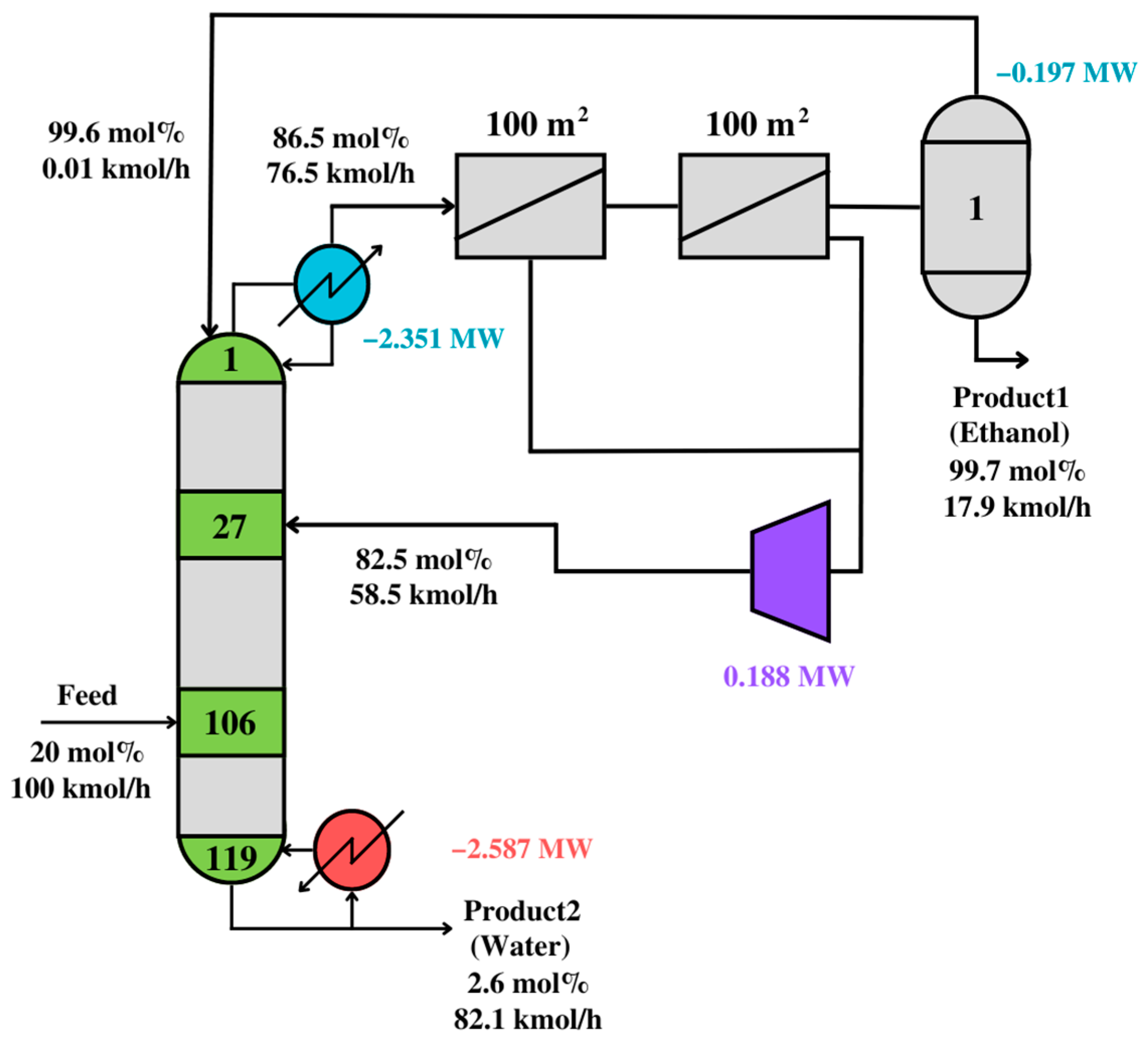
Figure 12 represent distillation modules with outlet or inlet flows higher than 15 kmol/h. The selected membrane module consists of two membranes connected in series. Connections between modules show optimal vapor and liquid paths, minimizing utility and membrane costs.
The optimal solution is interpreted, simulated, and validated. Thus,
Figure 12 shows the simulation result after the interpretation step. Since the simulation result is similar to the synthesis problem, the interpreted solution is assumed to be valid.
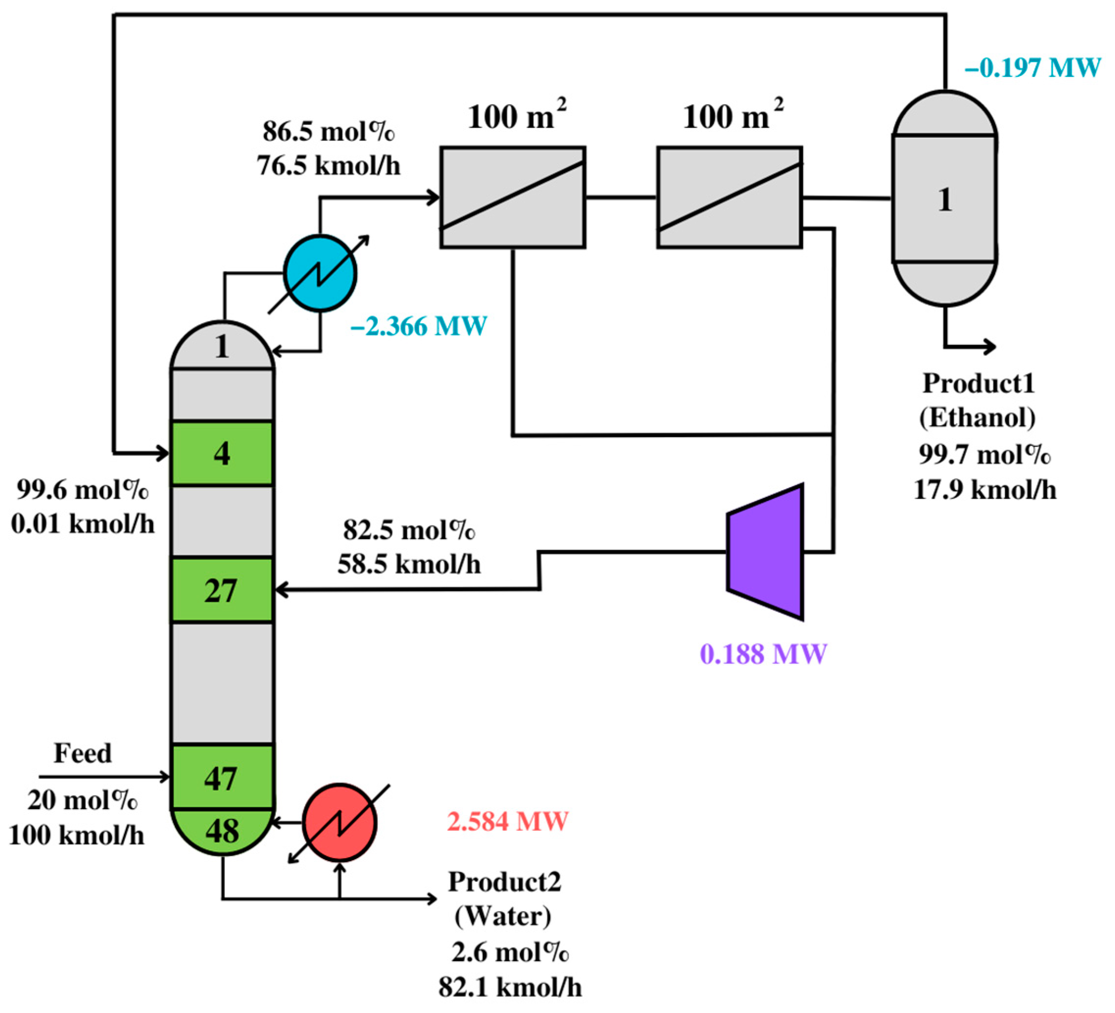
It is worth mentioning that the synthesis problem finds optimal paths of material and energy flows which minimize the utility cost. Therefore, the solutions will have as many distillation modules as possible to find a solution near the minimum reflux condition (i.e., minimum energy consumption). Thus, the post-optimization step will find a design with a better compromise between energy and equipment costs by minimizing the Total Annual Cost (TAC).
Table 9 compares the solutions from
Figure 11,
Figure 12 and
Figure 13. The solutions have similar energy consumption, but the post-optimized solution has fewer stages.
The utility costs in the compared steps of the synthesis problem are very similar, meaning that the synthesis problem finds the mathematically optimal solution for an unknown process, the validated solution finds a near-optimal solution for a realistic, known process, and the post-optimized solution enhances the compromise between energy and equipment cost. The TAC for the design in
Figure 12 is 1,718,670
$/year, while that for
Figure 13 is 1,613,356
$/year. Thus, the proposed
PS+I framework can effectively synthesize and design optimal distillation-based processes. Nevertheless, this framework can be extended to any process, as long as functional modules are incorporated.
2.4. Current Limitations in the PS+I Framework
Currently, the two main limitations of the proposed framework are the following: (1) The framework needs visual interpretation, because the solution to the synthesis problem is plotted in a ternary diagram or in a binary diagram. Mathematically, the synthesis problem can be solved for any number of components, but multidimensional interpretations are still limited. (2) There is a lack of computational power, because as the number of modules increases, the computational time increases. For example, when solving the separation of the binary mixture in
Section 2.3, the problem had approximately 95,000 variables and the process took a few minutes, but for the separation of the ternary mixture in
Section 2.2, the problem had around 1.5 million variables, and it took approximately 1000 min. Therefore, the extension to multicomponent separation will exponentially increase the number of modules, and the computation time will increase to infinity. Therefore, it is very relevant to first understand the separation of binary and ternary mixtures and then propose methodologies that can be applied for multicomponent separation.

