Article

Design and Analysis of Smart Reconstruction Plate for Wireless Monitoring of Bone Regeneration and Fracture Healing in Maxillofacial Reconstruction Applications

Department of Mechatronics Engineering, Faculty of Engineering, The Built Environment and Technology, Nelson Mandela University, Port Elizabeth 6000, South Africa
*
Authors to whom correspondence should be addressed.
Metrology 2025, 5(2), 32; https://doi.org/10.3390/metrology5020032
Submission received: 1 February 2025 / Revised: 21 May 2025 / Accepted: 29 May 2025 / Published: 3 June 2025

Abstract

:
In Maxillofacial Reconstruction Applications (MRA), nonunion is one of the critical complications after the reconstruction process and fracture treatment, including bone grafts and vascularized flap. Nonunion describes the failure of a fractured bone to heal and mend after an extended period. Different systems and methods have been developed to monitor bone regeneration and fracture healing during and after the treatment. However, the developed systems have limitations and are yet to be used in MRA. The proposed smart reconstruction plate is a microdevice that could be used in MRA for wireless monitoring of fracture healing by measuring the forces applied to the reconstruction plate. The device is wireless and can transmit the acquired data to a human–machine interface or an application. The designed system is small and suitable for use in MRA. The results of finite element analysis, as well as experimental verification, showed the functionality of the proposed system in measuring small changes on the surface strain of the reconstruction plate and determining the corresponding load. By using the proposed system, continuous monitoring of bone regeneration and fracture healing in oral and maxillofacial areas is possible.

1. Introduction

In medical applications, advanced mechatronic systems and state-of-the-art engineering solutions have led to the development of novel surgical techniques, medical devices, and implantable micro/nano measurement systems. Such systems monitor the biological/healing process in the reconstruction area in different reconstruction applications. Monitoring Bone Regeneration and Fracture Healing (BRFH) is important in reconstruction applications in different body zones. In maxillofacial reconstruction applications (MRA), monitoring of the BRFH is important after different reconstruction processes including non-vascularized bone grafts and vascularized flap [1,2,3,4].
Nonunion is one of the critical complications after MRA and fracture treatment. Nonunion describes the failure of a fractured bone to heal and mend after an extended period and is defined as the absence of osseous bridging of the fracture a few weeks after treatment [5,6,7]. To reduce the incidence of nonunion, it is important to use a stable and rigid Reconstruction Plate (RP). In this case, surgeons prefer to use two miniplates to reduce the risks and complications during and after the treatment [8,9]. If the reconstruction process is not successful using two miniplates, in a secondary reconstruction process, a single large RP with ridged mechanical structure is employed with extra-oral approaches. The single large RP is also considered for the patients being non-compliant with the follow-up and instructions during the treatment [10,11,12].
The existing monitoring methods for bone healing after the reconstruction process include radiography, such as qualitative evaluation of panoramic and CBCT radiographs [13], and clinical examination. These monitoring methods are highly subjective in nature, limited in application, and discontinuous monitoring solutions. Moreover, radiation exposure can harm patients, thus imaging should only be performed when necessary. In general, during the MRA, diagnosis methods, including radiography and ultrasound techniques, are used when complications and pain occur [14]. The existing techniques are limited, and continuous monitoring of the BRFH is not possible using these techniques. Therefore, novel methods are required to address the current limitations and facilitate continuous monitoring of the BRFH in MRA.
In different studies, the mechanical performance of the RP’s in MRA is evaluated. The biomechanical behavior of a mandibular RP could address different conditions of the mandibular fractures. The authors in [15] explored a vast array of fixation philosophies and techniques to address the mandibular angle fractures. In this study, 14 fracture conditions were considered. A vertical load, ranging from 0 to 200 N, was applied to the incisal edge of the sample plate, while a contralateral load was applied to the molar region of the sample plate. The applied load, displacement, and stiffness were obtained. The results showed that in different reconstruction conditions, the force applied to the reconstruction mechanism varies. At the same time, a displacement in the mechanical structure of the RP occurs. The authors in [16] assessed the mechanical properties of different types of the reconstruction systems regarding their fracture under the applied load. The mandible models were resected on the side, between the third molar and canine, while loaded between 30 and 300 N. The results of this study showed all plates fractured close to the distal fragment. The plates deformed under the applied load. Thus, the mechanical characteristics of the RP used in the MRA are an important factor.
Recent studies demonstrate that BRFH can be monitored by measuring the applied force to the RP. The applied force causes a deflection on the surface of the RP, which could be detected using advanced measurement techniques, and accordingly, the amount of corresponding force could be calculated. During the BRFH process, the newly formed bone tissue is consolidated and the amount of force applied to the RP is reduced. Consequently, monitoring surface deflection provides insight into the healing process.
In a recent study conducted by [17], a surface strain measurement system based on a MEMS strain gauge was used to evaluate the functionality of this technique in monitoring the surface deflections of the mandibular RP on an ex vivo model. Figure 1 illustrates the experimental stand for surface strain measurement to assess the efficacy of this technique for MRA. The results of this study show that it is possible to use a surface strain measurement system to monitor the force applied to the RP during the bone healing process in MRA. Measuring implant strain in a RP is an appropriate method for registering and monitoring the BRFH in the mandible. The results of this study show that it is possible to implement a surface strain measurement technique for bone healing monitoring during MRA. However, the measurement device used in this study is limited in size and technology, and it is impossible to use this technique in MRA. There is still a gap between the existing techniques and an ideal solution for BRFH monitoring in MRA.
In this paper, a novel system and method for monitoring the BRFH during MRA is proposed. The proposed device is a wireless smart RP that measures the surface strain of the RP with high precision. Using an energy harvester mechanism, the measurement system is charged and activated, and the amount of surface deflection in the RP is measured. The control system transmits the acquired data to an extracorporeal receiver using a wireless communication protocol. The extracorporeal part of the device includes an ultrasonic energy transmitter, a control unit for communicating with the implanted control unit, and a human–machine interface (HMI). The proposed device is small, meets the limitations of the existing techniques in MRA, and could be used as a suitable solution for wireless monitoring of the BRFH during MRA. Compared to [17], which utilized a larger Bluetooth-based system with a Li-ion battery, our approach eliminates the need for bulky power sources and provides better integration with MRA.

2. Material and Methods

2.1. Theory and Principles

The proposed smart RP for monitoring the BRFH in MRA consists of different mechanical and electrical components that function cohesively to measure the applied force to the RP and transmit data via wireless communication. Since a correlation exists between the force applied to the RP and the regenerated bone tissue, the measured force could be used as a factor for monitoring the BRFH, where a decrease in the amount of the force applied to the RP indicates an increase in the amount of regenerated bone tissue as well as the progression of the fracture healing progress. Using the MEMS strain gauge measurement technique, the surface deflection of the RP could be precisely measured and used by the control system to calculate the amount of the applied force to the RP.
The designed method consists of five main parts: the mechanical RP; the strain measurement mechanism which is bonded on the surface of the RP (mechanical means); the control system for measuring the surface strain of the RP; wireless data transmission (electrical means); the energy harvester system for supplying the system and activating the mechanism; the extracorporeal part including the ultrasonic transducer; and the receiver. The block diagram of the designed system is presented in Figure 2. By using a wireless communication technique, the acquired data can be transmitted to the extracorporeal receiver. An application, software, or an electronic system could be used to receive and monitor the transmitted data. Moreover, a piezoelectric ultrasonic energy harvester system is implemented within the designed mechanism to generate the required energy to monitor the progress of BRFH. An extracorporeal energy transmitter—an ultrasound energy transmitter—is used to energize the energy harvester and run the measurement system. By using this technique, continuous monitoring of the BRFH is possible.
Figure 3 illustrates the schematic layout of the proposed smart RP. In this configuration, an external ultrasonic piezoelectric transducer is placed on the skin above the implanted device to transmit ultrasonic waves through the tissue toward the energy harvesting system. A small oscillator receiver, which is part of the piezoelectric ultrasonic energy harvesting setup, captures these ultrasound waves and initiates vibrations. The oscillator converts these vibrations into a stepwise motion actuation, enabling the harvested vibration energy to be transformed into electrical energy. The receiver’s role is to convert inaudible sound into electrical power. This collected electrical energy is then stored to energize the system that monitors the surface strain of the RP using the strain gauges attached to the surface of the RP. Additionally, Figure 3 presents the initial modeling and design of the smart RP. To accurately measure surface deflections, four strain gauges are affixed on the surface of the RP, allowing for precise determination of deflections across the plate surface in two dimensions. A high-performance control system, featuring a high-precision amplifier and an analog-to-digital converter, is used to monitor small variations in the impedance of the strain gauge configuration, which occur due to surface strain within the RP in the healing zone.

2.1.1. Strain Gauge Characteristics

In the proposed BRFH monitoring system, the strain gauges are bonded on the surface of the RP to measure the change in the resistance of the strain gauge that is caused by the change in the surface deflection of the RP under the applied load. The magnitude of the mechanical deformation of the RP is very small, and, therefore, the corresponding strain could be expressed as a micro-strain. The micro-strain (µɛ) is calculated from the change in length relative to the original length (∆L/L). The gauge factor (GF) relates this strain to a measurable resistance change (∆R), which is detected using a Wheatstone bridge. The output voltage (Vo) from the bridge is amplified and used to infer the applied force. Four strain gauges are attached to the surface of the reactive platform (RP), arranged parallel to the X- and Y-axis. In this configuration, the RP structure is designed as two cantilever beams; when a force is applied in the corresponding direction, it leads to deflection on the RP’s surface, which alters the resistance of the strain gauges and thus influences the output voltage of the strain gauge arrangement. A Wheatstone bridge is utilized, featuring four arms with resistive components that convert the captured signal into a bipolar voltage output, which can then be amplified and measured. In this condition, the output voltage could be calculated using the following equation:
V O = V e ( R 3 R 3 + R 4 R 2 R 1 + R 2 )
where Vo represents the output voltage that is measured, Ve indicates the excitation voltage, and R1–4 are the resistive components arranged in a Wheatstone bridge setup, where R1 is equal to R2 and R3 is equal to R4. When an active strain gauge is incorporated into in the Wheatstone bridge configuration (where R4 becomes R4 ± ∆R), the change in the output of the bridge is directly linked to the variation in the resistance of the strain gauge (∆R). This Wheatstone bridge arrangement facilitates the accurate measurement of minor fluctuations in the strain gauge’s resistance by applying the following equation:
R = R s G F ɛ i
where Rs represents the resistance of the strain gauge element under no load conditions, GF denotes the gauge factor of the strain gauge, and ɛi is the strain experienced by the strain gauge. The change in the strain can be determined by measuring the output voltage of the Wheatstone bridge. The output voltage of the configured bridge network can be expressed using the following equation:
V o = V e G F ɛ 4 1 ( 1 + ( G F ɛ 2 )
In this specific condition, variations in the resistance of the active strain gauges may lead to alterations in the output voltage. Utilizing the equation provided below, it becomes feasible to quantify the strain, and consequently, ascertain the applied force.
V o = V e G F ɛ
Also, the sensitivity of the designed bridge could be expressed as follows:
S e n s i t i v i t y = V o V e = G F ɛ   [ m V V ]
Using the above-mentioned equations and the specifications of the strain gauge used in the measurement system’s configuration, the control system can determine the amount of change in the resistance of the strain gauge bridges and the corresponding applied force.
Surface strain measurement of the RP during the reconstruction process requires a high-precision measurement system as the change in the mechanical formation of the RP body is very small, resulting in small changes in the resistance of the strain gauge configuration. To ensure accuracy, a high-sensitivity measurement system with a precision amplifier and ADC is used. These measurements enable us to monitor small surface deflections correlated with the healing progress.

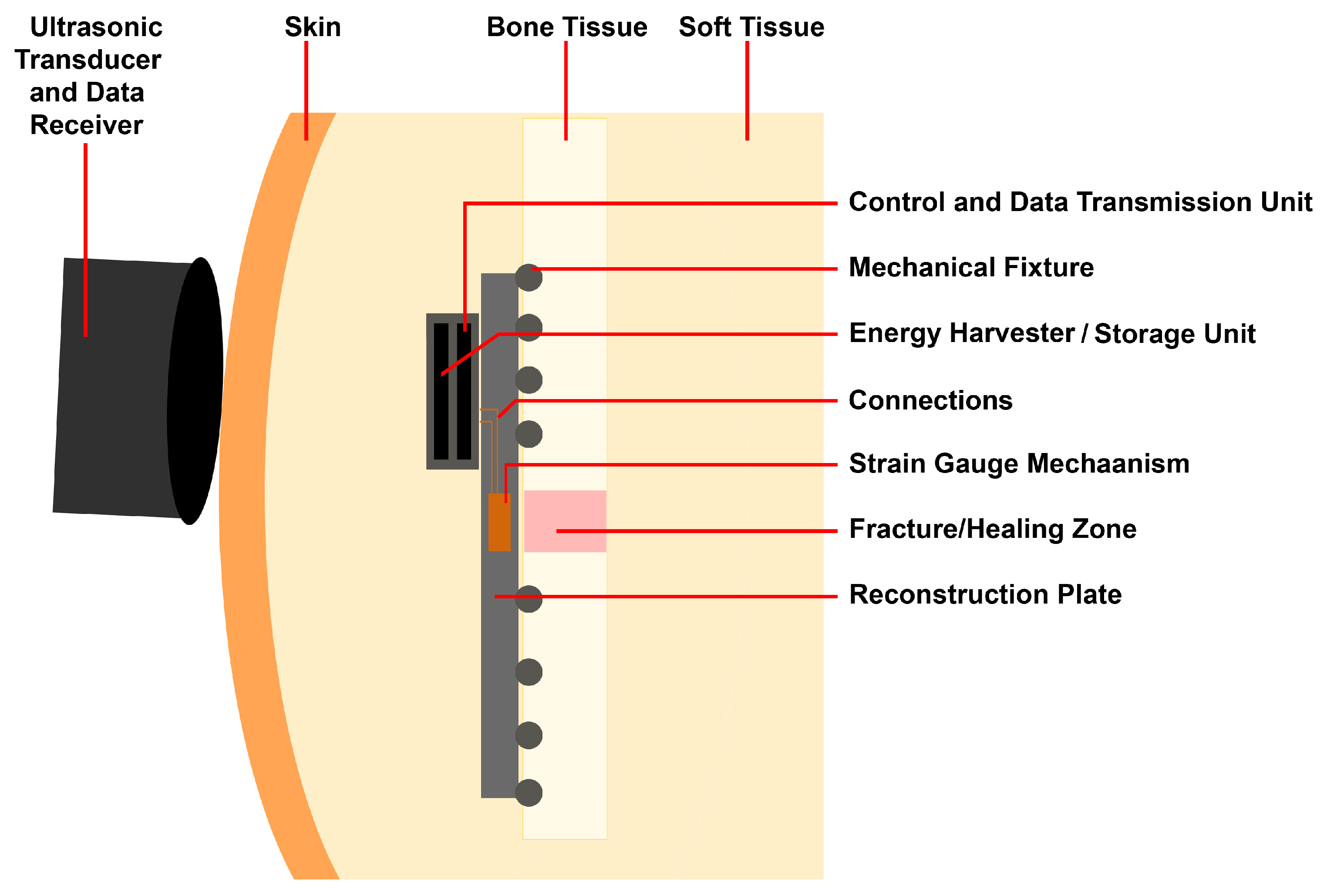
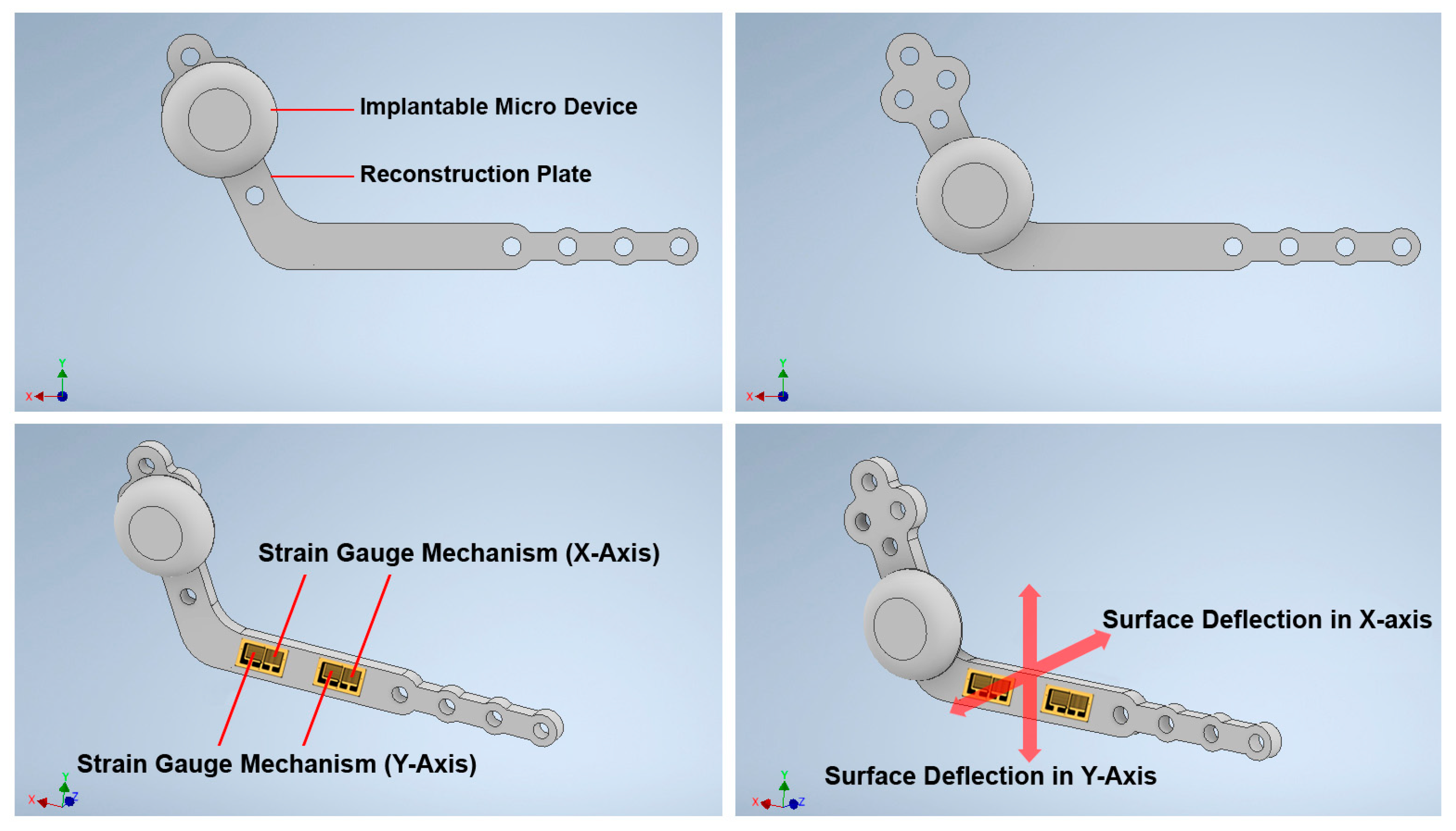
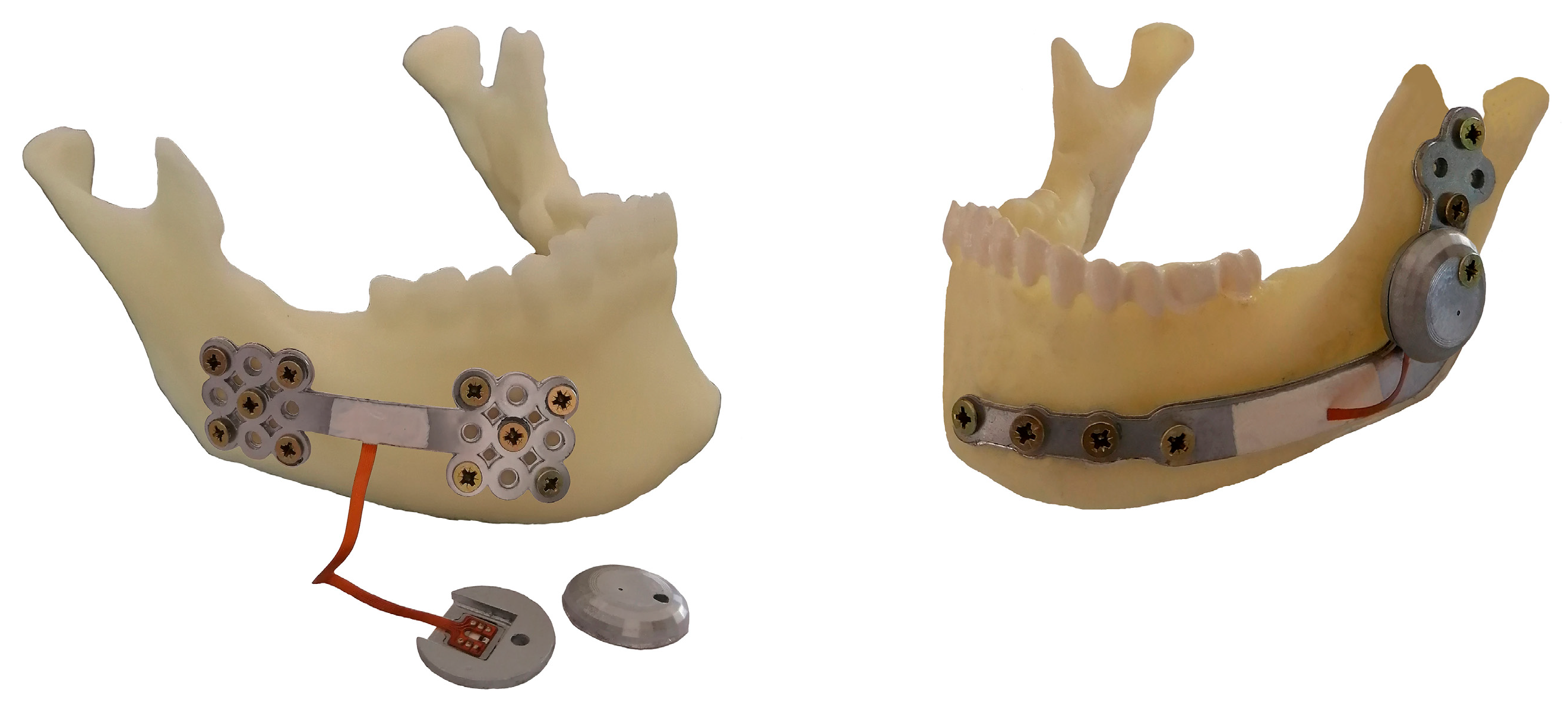
2.1.2. Structure Design of the Customized Reconstruction Plate

Recent advances in 3D printing technologies have enabled 3D printing of Ti-6Al-4V with high-precision surface accuracy for advanced applications in different fields of industry. In MRA, the application of 3D printing Ti-6Al-4V is important and can play a significant role in the development of next-generation implants and customized mandible RPs. By using a Computerized Tomography (CT) scan and anatomical data of a specific patient, it is possible to design and manufacture a customized RP with high accuracy and precision to meet the individual requirements and specifications of the RP in terms of shape, size, and mechanical characteristics. It is possible to select specific plate design features including profile length, height, and the run of the RP. Moreover, the number and the location of the screw holes can be customized according to the requirements and conditions of the treatment. Customized RP can be manufactured and used in the proposed system/method for monitoring the BRFH. It is possible to manufacture the desired RP from Ti-6Al-4V material using 3D printing technologies. Also, different subtractive methods, such as cutting processes and Computer Numerical Control (CNC) machinery, can be used to manufacture customized reconstruction plates out of titanium alloys with high precision. The typical design of the mechanical structure used in the proposed system is presented in Figure 4. The mechanical structure of the RP body should be rigid and stable to suit the reconstruction process. A typically used thickness of 3 mm is considered in the sample design and surface strain analysis of the RP to meet the standard factors in terms of mechanical characteristics and size of the plate.

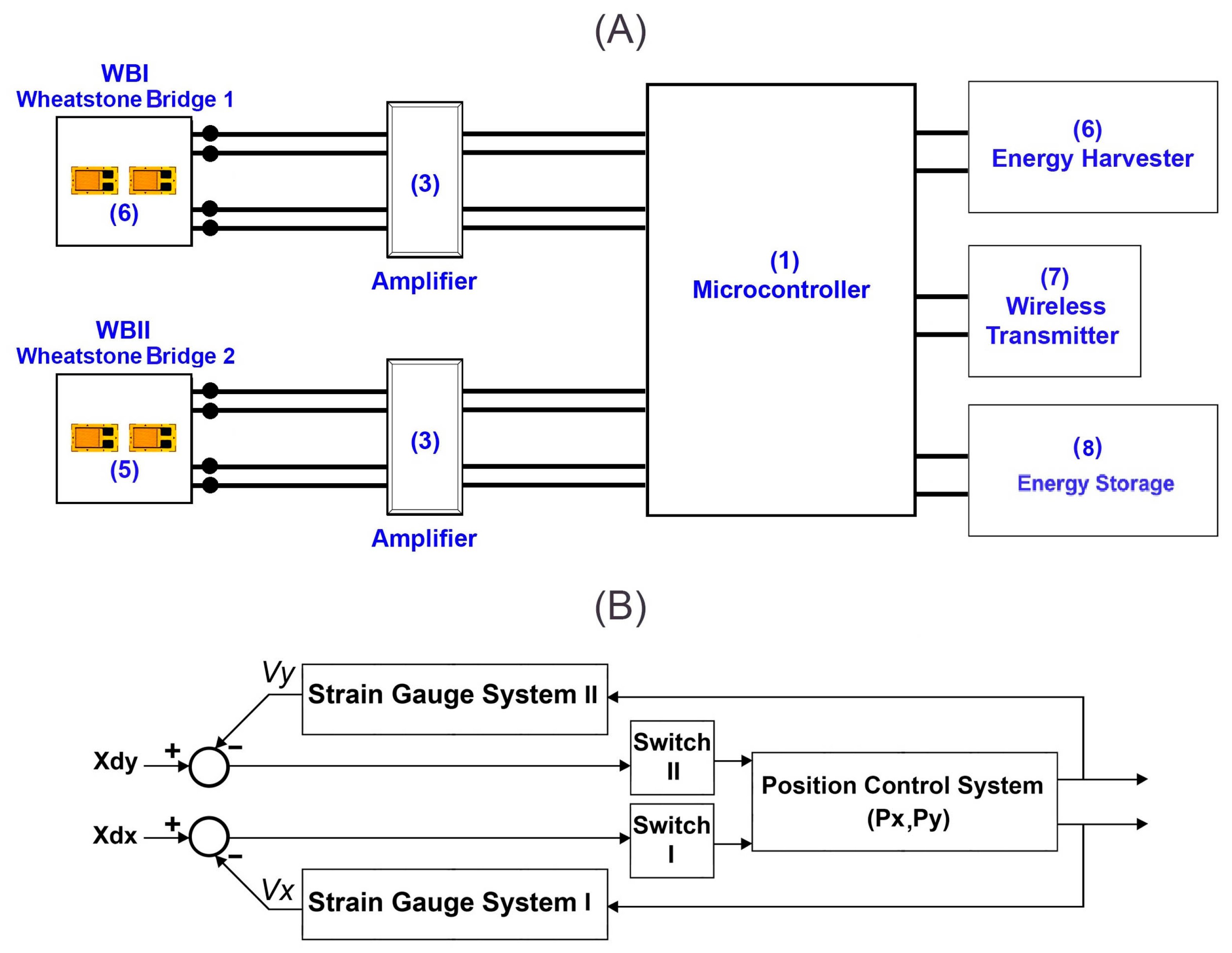
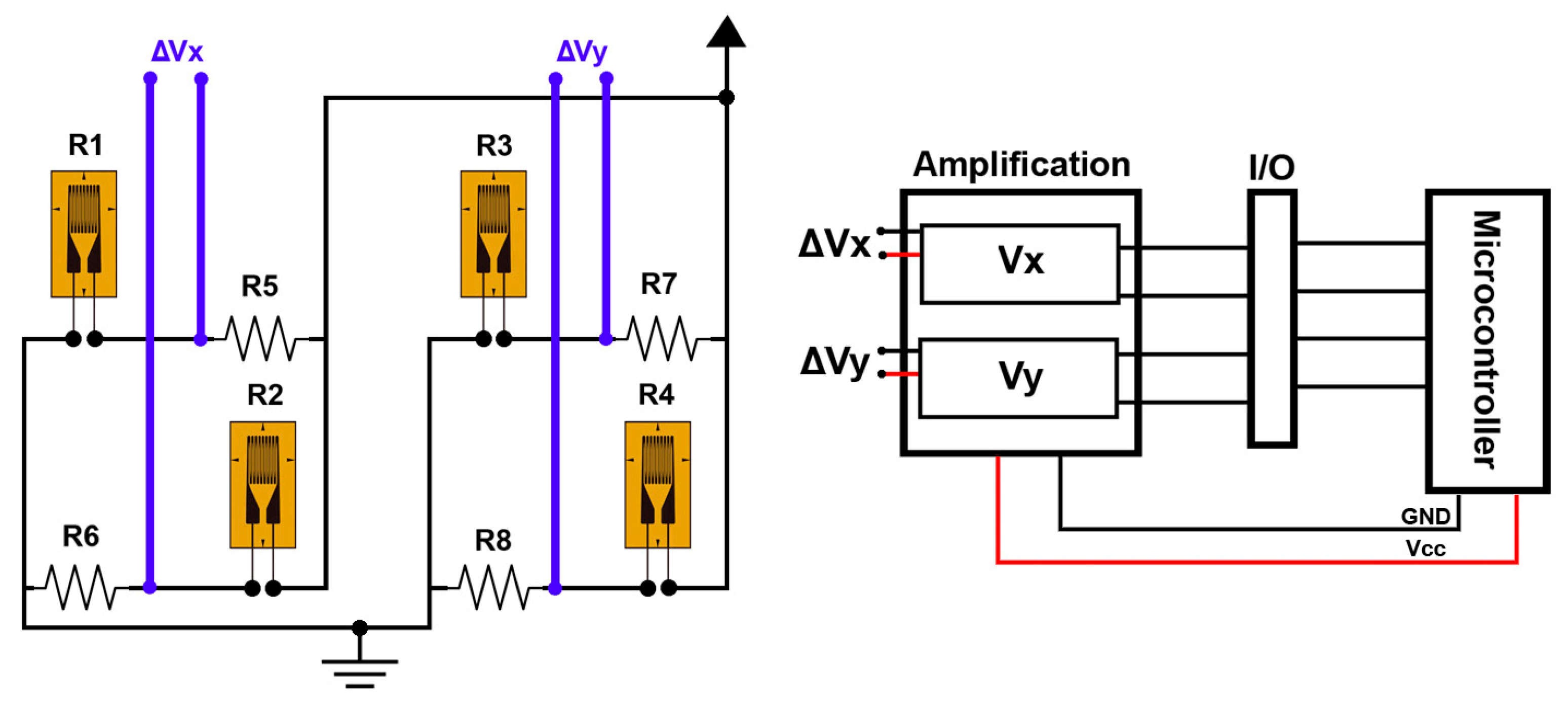
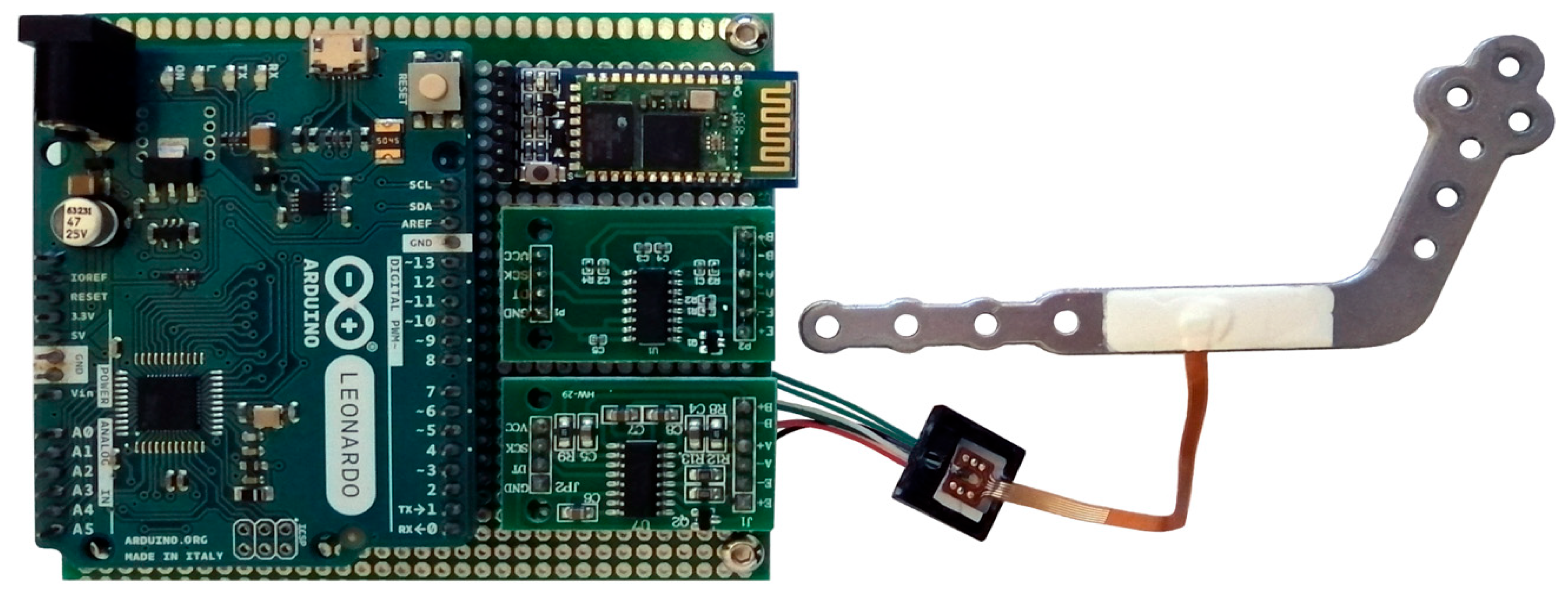
2.2. Control System and Measurement Principles

The control system should be able to distinguish the small changes in the output voltage of the strain gauge configurations so that the small amounts of surface strain can be measured. In the designed mechanism, four strain gauges are used to enable force measurement in two directions, the X- and Y-axis. Two strain gauges are sensitive to the surface deflection parallel to the X-axis, and two strain gauges are sensitive to the surface deflection parallel to the Y-axis. Using the proposed control system, the deformation on the surface is measured in two directions, and the applied force corresponding to the surface deflection is indirectly calculated. The outputs of strain gauges are used as position feedback to identify the position errors that occurred. The position feedbacks are used in the designed closed-loop control system to measure the surface deformities caused by the applied force. Moreover, the control system should be able to transmit the acquired data using wireless communication protocols.
Figure 5 presents the schematic design and principles of the control system. The main components of the control system include a microcontroller (1), two load cell amplifiers with a 24-bit analog to digital converter (2) and (3), two strain gauge configurations (4) and (5), and a wireless module (7). In addition, a piezoelectric ultrasonic energy harvester (6) is implemented within the system to generate and charge the energy storage system (8) to run the measurement system and transmit the data. The ultrasonic energy harvesting system operates by converting focused ultrasonic waves from an external transducer into mechanical vibrations, which are then converted into electrical energy by a piezoelectric oscillator. This harvested energy powers the control and communication systems. Compared to traditional battery-powered systems, this method provides a safer, smaller, and long-term power solution suitable for MRA. The Wheatstone bridge strain gauges are linked to amplifiers to boost the acquired signals. The output from these amplifiers is connected to the digital pins of the microcontroller, enabling the measurement of changes in the amplified signals. The microcontroller can recognize fluctuations in the measured voltage, which allows for the calculation of the corresponding surface deflection. By evaluating the strain or tension on the surface of the RP, it is possible to determine the force applied to it. Through the use of wireless communication protocols, the control system can connect to either a Bluetooth or WiFi network to send the collected data. Figure 5 illustrates the block diagram of the position control loops utilized within the control system. The control system runs two independent closed-loop control algorithms at the same time to assess the forces applied in both X- and Y-directions.

2.2.1. The Arrangement Strategy of the Strain Gauges

As illustrated in Figure 4 and Figure 5, two pairs of strain gauges are bonded on the surface of the RP around the highest strain while considering maximizing the sensitivity of the force measurement along the X- and Y-axis. Two active strain gauges R1 and R2 are arranged on the surface of the RP along the X-axis to detect the applied force along the X-axis. Other active strain gauges R3 and R4 are arranged on the surface of the RP along the Y-axis to detect the applied force along the Y-axis. The strain gauges are bonded on the surfaces in a Wheatstone half-bridge configuration.
The resistance of the strain gauges will change when external forces are applied to the RP. Table 1 presents the variations in resistance for each strain gauge. Here, Fx denotes the force applied along the X-axis, while Fy indicates the force applied along the Y-axis. As depicted in Figure 6, the Wheatstone bridges are excited by a voltage supply, resulting in the corresponding output voltage ∆Vi appearing at the measurement terminals of each bridge. The following equations express the output signals from the Wheatstone bridges:
V x = V e 4 ± R 1 R 1 ± R 2 R 2
V y = V e 4 ± R 3 R 3 ± R 4 R 4
where the ∆Ri/Ri denotes the rate of variation in resistance of the gauge Ri, ∆Vx indicates the change in the output voltage of the Wheatstone bridge along the X-axis, while ∆Vy refers to the change in output voltage of the Wheatstone bridge along the Y-axis. Furthermore, Ri specifies the quantity of strain gauges used in each Wheatstone bridge configuration.

2.2.2. Decoupling the Surface Strain and Respective Applied Forces

Two groups of strain gauges are bonded to the surface of the RP. The outputs from these gauges are DC voltages that are acquired, amplified, and subsequently used to calculate the applied force based on the changes in the output voltage of each Wheatstone bridge. During the measurement process, a specific DC voltage (5 VDC) is applied to the input terminals of each Wheatstone bridge. The applied force results in changes to the surface strain, while the resistance of the strain gauges varies in response to the stress or tension exerted on the bonded surface of the RP. The relationship between the changes in the output voltage and the applied force can be expressed by the following equation:
V x = K s x . F x V y = K s y . F y
where ∆Vx and ∆Vy represent the changes in voltage for each Wheatstone bridge resulting from the applied forces Fx and Fy, respectively. The constants Ksx and Ksy correspond to the relationship between the changes in output voltage and the respective force applied. The control system implements a decoupling measurement algorithm, which can be expressed as follows:
F x F y = 1 / K s x 0 0 1 / K S y V x V y
By using Equation (11), the following equation could express the relationship between the applied force and the change in surface strain:
ɛ x = K ɛ x V x ± G F . V e ɛ y = K ɛ y V y ± G F . V e
where ɛ x and ɛ y represent the changes in the strain on the RP surface due to the applied forces Fx and Fy respectively. K ɛ x and K ɛ y are corresponding constants that indicate the relationship between surface strain changes and the applied forces. V x and V y denote the changes in output voltage from the strain gauge bridge on the X- and Y-axis, respectively. Ve is the input voltage supplied to the strain gauge bridge, and GF is the gauge factor. The decoupling measurement algorithm utilized in the control system can be expressed as follows:
ɛ x ɛ y = K ɛ x ± G F . V e 0 0 K ɛ y ± G F . V e V x V y
Therefore, when an external force is applied to the RP structure, the surface strain, which causes surface strain and positioning error in the corresponding axis, is determined.

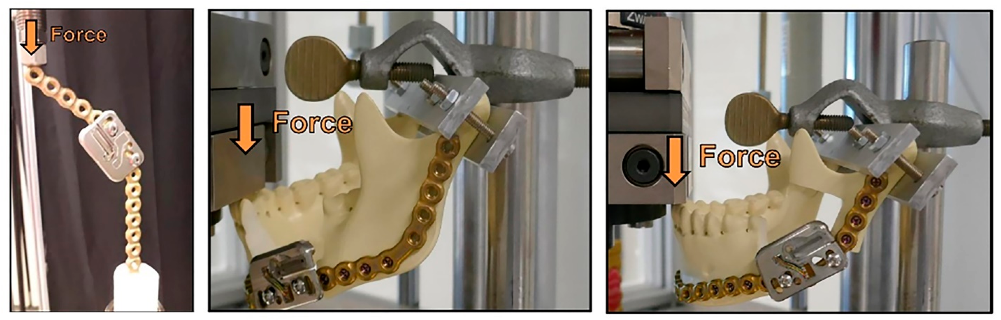
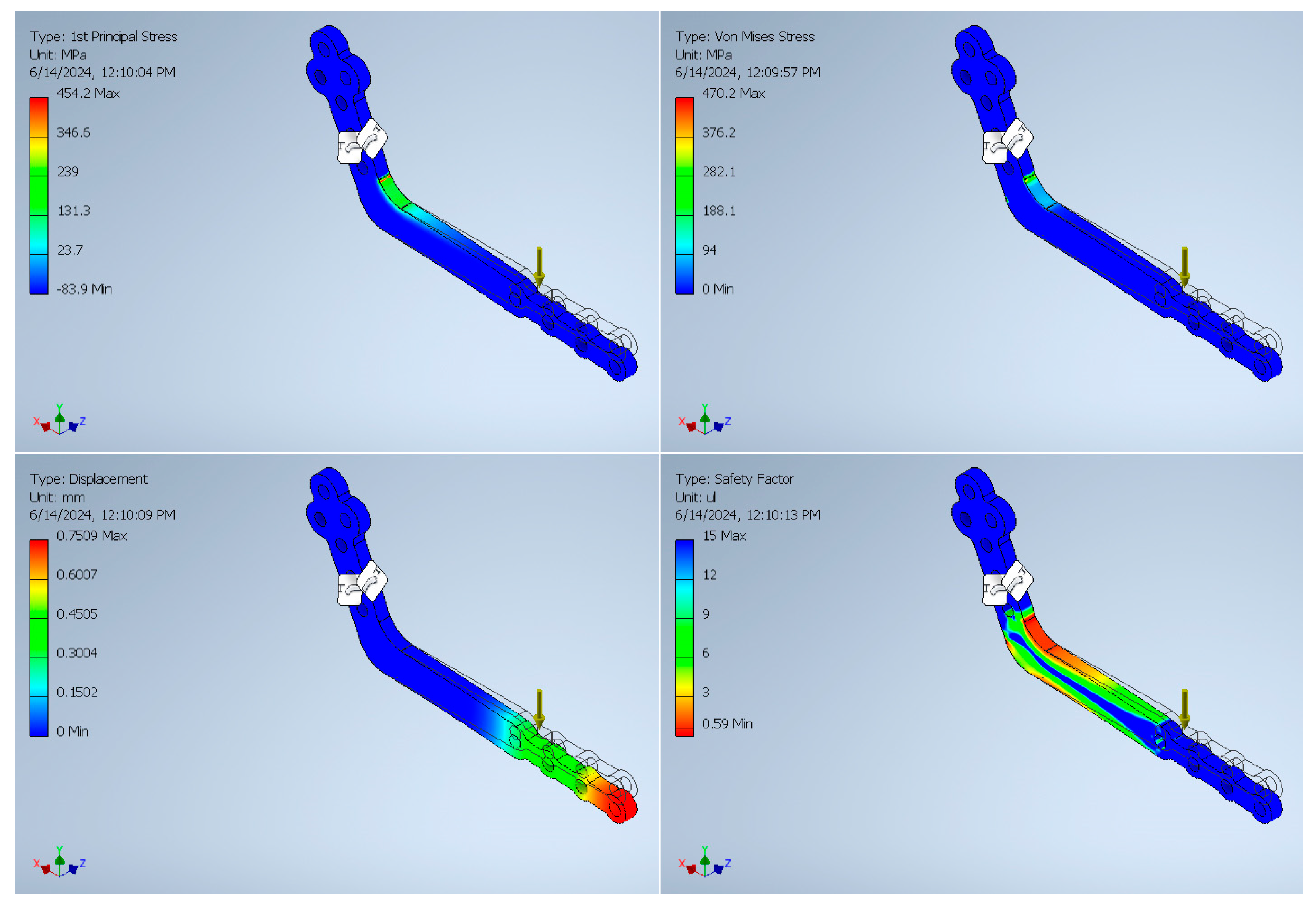
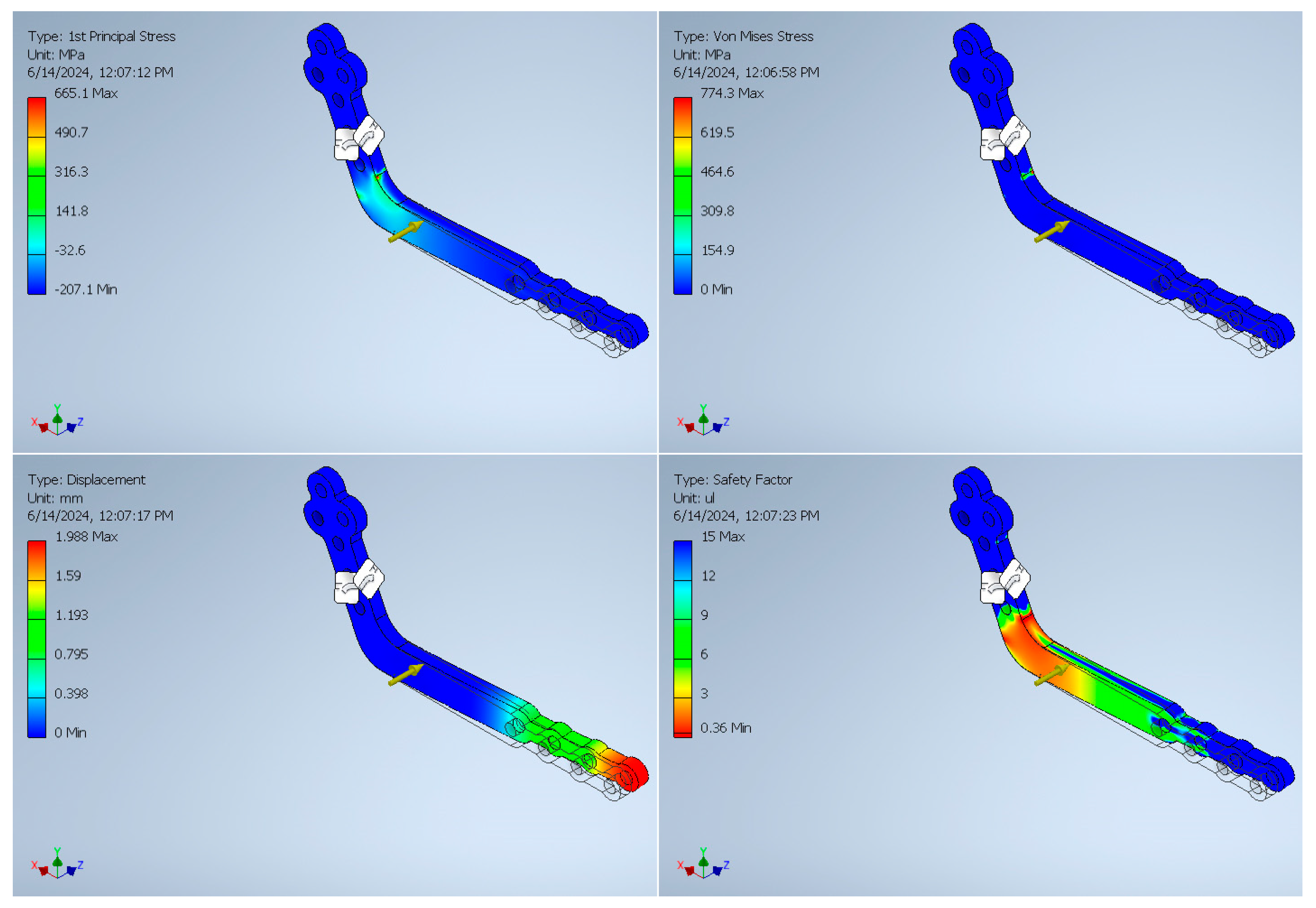
3. Finite Element Analysis Validation

To verify the measurement mechanism and assess the performance of the proposed smart RP concerning changes in surface strain under applied force, a finite element analysis (FEA) was conducted using Autodesk Inventor Professional 2022 software. Stiffness serves as a crucial metric, defined as the ratio of the input load to the corresponding displacement at the mechanism’s input end. The impact of applying external forces on surface strain was simulated through two models, demonstrating how the applied forces influenced the surface strain of the RP along Y and Z axes. A 2.8 mm thick titanium substrate was selected, with design specifications adapted to the standard conditions. According to the literature, during the reconstruction process, a peak force of 200 N is applied to the healing zone during standard functions such as biting or eating [15]. A static force of 200 N was set and applied to the RP in each model. FEA assesses the safety of the designed platform by applying the respective input force or displacement at the input of the mechanism. The results of the surface strain analysis, and the applied force and corresponding deformation displacements are presented in Figure 7 and Figure 8, respectively. The results show that the model has a volume of 4855 mm3 and a mass of 0.02 kg with a safety factor of 15 µL. Figure 7 indicates a maximum stress of 454.2 MPa is applied to the model when a pushing force of 200 N is applied to the reconstruction plate in the Y-axis which causes a maximum displacement of 0.75 mm on the RP. Figure 8 illustrates an applied force of 200 N in the Z-axis causes a maximum stress of 665.1 MPA and a displacement of 1.98 mm on the RP. In typical scenarios, the force applied to the RP is parallel with the Y-axis during common activities (e.g., chewing and biting). The FEA confirms that under all test conditions, the designed platform demonstrates high strength, guaranteeing linearity, precision, and repeatability throughout the treatment process.
The results from FEA were instrumental in validating the mechanical integrity of the RP under expected mechanical loads. These findings informed the choice of Ti-6Al-4V as the plate material and confirmed that the plate geometry would provide sufficient sensitivity for strain measurement while maintaining structural stability. This simulation-guided design process ensured that the final prototype would perform reliably in real-world conditions.

4. Analysis of the Control System and Experimental Results

An experimental study was performed to evaluate the sensitivity and accuracy of the proposed measurement technique by observing small surface deflections of the RP under different conditions. Figure 9 presents the detailed design of the system and components used to analyze the control system and measurement technique. After the measurement system was developed and the strain gauges installed on a manufactured RP, the sensor was calibrated, and the experiments were performed.
A customized RP model was designed and manufactured from Ti6Al4V, and the strain gauge components were bonded on the surface of the RP in a Wheatstone half-bridge configuration, as illustrated in Figure 9. Using the method and principles presented in Section 2.2, an electronic circuit was developed for the experiment to acquire the output signals of the Wheatstone bridges. Two HX711 load cell amplifiers, with a 24-bit analog to digital converter, were implemented within the system to amplify the acquired voltage signals with high precision and to read the change in the voltage of the Wheatstone bridges. The HX711 communicated with the microcontroller via a two-wire interface (data and clock). The Wheatstone bridges were connected to the HX711 amplifiers, and the output of the HX711 was connected to the digital pins of a microcontroller board. The change in the measured voltage was distinguished via the microcontroller, the corresponding surface strain was calculated, and the respective force applied to the RP was determined.
In the control system, an Arduino Leonardo microcontroller board, based on the ATmega32u4 microcontroller with a 16 MHz crystal oscillator, received the data from the amplifiers and calculated the surface strain and respective forces applied to the RP. An HC-05 Bluetooth module was connected to the microcontroller to transmit the data to an application. Using the MIT app Inventor development tool, an application communicated with the control system, received the data, and monitored the measured forces applied to the RP. Figure 10 presents the developed measurement system. The control system sensed small changes in the output signal of the strain gauge bridge when a small amount of force was applied to the surface of the RP. The strain gauges used in this system are fabricated with platinum and polyimide layers, ensuring high biocompatibility. To mitigate the risk of galvanic corrosion, the gauges are coated with a medical-grade waterproof polymer that isolates them from the titanium RP. This protective layer also improves durability and allows safe long-term implantation in biological environments.

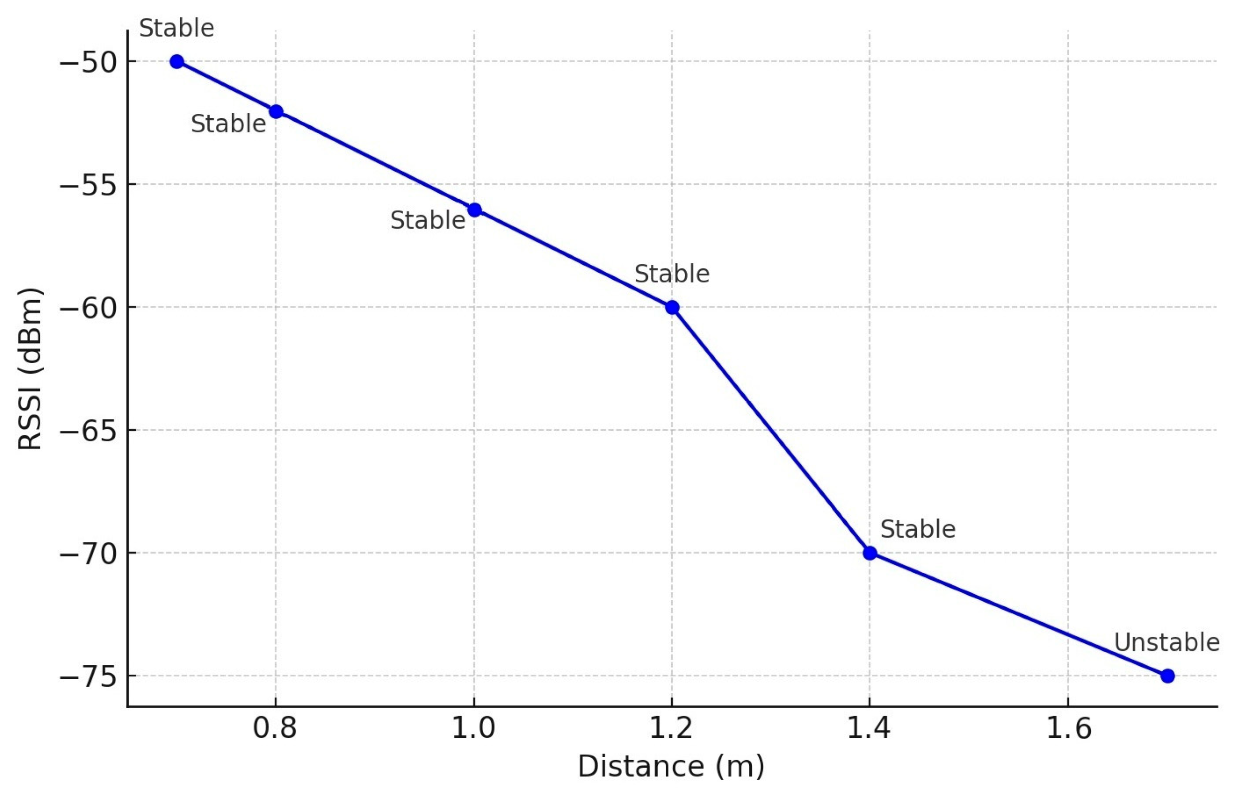
4.1. Signal-to-Noise Ratio (SNR) and Transmission Range Measurement

The Signal-to-Noise Ratio (SNR) was evaluated under varying experimental conditions to assess the integrity of the wireless communication link between the sensor node and the Arduino-based receiver using the HC-05 Bluetooth module. Signal strength estimation was performed in inquiry mode, which returns the Received Signal Strength Indicator (RSSI) for nearby Bluetooth devices. The SNR was calculated by comparing the measured RSSI values to an assumed noise floor, which represents the ambient radio frequency (RF) noise present in the environment. In a typical indoor laboratory setting, the noise floor in the 2.4 GHz band is approximately −90 dBm. For each test scenario, the RSSI value corresponding to the HC-05 module was recorded during inquiry mode, and the SNR was calculated accordingly. The results, summarized in Table 2, present the measured RSSI values in Bluetooth inquiry mode. The SNR consistently exceeds 25 dB in the best-case scenario, which supports stable data transmission with minimal interference.
The transmission range of the wireless communication link between the transmitter and the receiver is a crucial parameter to assess the viability of the system for use in biomedical applications, such as sensor-based monitoring of physiological conditions. For this study, to simulate real-world conditions where Bluetooth signals would traverse biological tissues, a tissue equivalent material (TEM) was used. The TEM used in this study is a synthetic mixture of water, salt, and agar that mimics the dielectric properties of human tissues. The transmission range of the Bluetooth link was measured by placing the sensor and receiver within varying distances through the TEM. The HC-05 Bluetooth module attached to the sensor node was placed on one side of the tissue equivalent material. The Arduino-based receiver, also equipped with an HC-05 module, was placed on the opposite side of the TEM, initially at a 0.5 m distance and gradually increased up to 1.8 m. The RSSI value was recorded for each distance using Bluetooth inquiry mode. The connection was verified based on the ability of the receiver to establish and maintain stable communication with the sensor node at each distance.
Figure 11 presents the transmission range through TEM. The results show that the Bluetooth signal remained stable up to a distance of 1.4 m with the RSSI maintaining values between −50 dBm and −70 dBm. At 1.6 m, the signal became unstable, and the RSSI dropped below the threshold necessary for reliable communication. Therefore, the ideal transmission range through the tissue equivalent material is approximately 1.5 m.

4.2. Calibration of the Sensor

The proposed measurement technique is sensitive to small surface deflections. Therefore, the output signals of the Wheatstone bridges after the amplification should be calibrated to ensure an accurate and high-precision measurement is achieved. It is possible to calibrate the measurement system on different types of RPs with different mechanical specifications. When a specific RP is designed and manufactured according to the treatment and patient conditions, the measurement system is bonded on the surface of the specifically designed RP. The measurement system can be calibrated using the equations below.
Based on the evaluation technique used, a maximum surface deflection and a maximum surface stress of the designed RP can reach ẟmax = 0.75 mm and 454.2 MPa, respectively, when a maximum external force of 200 N is applied to the RP in the Y-axis. The linear relationship of the amplified signals could be used for impedance calibration. When a load M is applied to the RP, it can be expressed as the following linear equation:
y = m x + b
where m presents the slope of the calibration line and b is the intercept where y = 0. b is considered the tare point when no force is applied to the RP. When x0 and y0 are used as the first point on the line, x1 and y1 could be defined as the second point and expressed as follows:
b = y 0 x 1 y 1 x 0 x 1 x 0
Therefore, the final expression of the calibration line using two masses could be expressed as follows:
y = y 1 y 0 x 1 x 0 x + y 0 x 1 y 1 x 0 x 1 x 0

5. Discussion

The application of the smart RPs and orthopedic implants for monitoring the BRFH has been under investigation since 2000 [18]. Different measurement techniques have been used in developing the smart RPs for monitoring the BRFH in different body zones. In 2016, Fountain et al. [19] proposed a biomechanical monitoring system for the BRFH assessment in limb reconstruction. However, this method cannot be used in the early stage of healing when tissue is fragile; it is suitable for externally fixated fractures. In 2022, Windolf et al. [20] proposed a bone healing monitoring system using an implantable load cell measurement system. This method was used in animal testing during limb reconstruction on a sheep model. For this purpose, a wireless load cell sensor was fixed to a large RP used in the reconstruction process. The obtained results revealed that it is possible to use a load cell mechanism for continuous monitoring of the BRFH. In another study in 2022 [17], the same measurement technique was used to assess the feasibility of the strain measurement technique for BRFH monitoring in MRA. The results of this study showed that it is possible to measure the surface deflections of the RP using strain measurement techniques. The strain measurement of the RP surface proved to be a suitable technique to be used for continuous monitoring of the BRFH. The existing technologies are limited by their size, mechanical design, power source and measurement method, relying on a bulky Li-ion battery and mechanical fixtures. These characteristics pose significant challenges for use in MRA, where compactness, safety, and implantability are crucial.
This research work presents a novel system and method for direct measurement of the surface strain of the RP and wireless monitoring of bone healing. By measuring the surface deflections of the RP, the corresponding load applied to the plate is measured. The proposed system employs ultrasonic energy harvesting, eliminating the need for implanted batteries and significantly reducing device size. This method also improves long-term safety and biocompatibility. Moreover, the wireless communication protocol is designed for efficient data transmission through soft tissues, making it ideal for the maxillofacial region. The system is fully customizable for individual patients using 3D-printed Ti-6Al-4V RPs. These features enable real-time, continuous, and safe monitoring of the BRFH process. Table 3 presents a comparison highlighting the novelty of the presented method for assessing bone healing in MRA.
Finite element analysis (FEA) and experimental studies were conducted to evaluate the system’s functionality and method for high-accuracy surface strain monitoring of the RP. The results demonstrate that the proposed method can precisely detect minor strain variations, providing a valuable metric for evaluating bone regeneration and healing progress. The system maintained a stable transmission range up to 1.5 m through TEM. The SNR was measured at >25 dB, sufficient for reliable monitoring indicating suitability for in vivo conditions. These results indicate that the communication link maintains sufficient signal quality to ensure reliable data transmission in typical operational environments.
Recently, 3D printing of titanium has enabled the making of custom RPs with desired mechanical and physical specifications for patients. It is important to use customized RPs to improve the mechanical performance of the RP in MRA [21,22]. Using customized RP improves the biomechanical performance and optimize the mechanical strength in MRA [21,23,24,25,26]. In the proposed method, the RP is designed from biocompatible titanium alloy (Ti-6Al-4V), which is biocompatible and commonly used in clinical applications. The mounted strain gauge system is isolated from the bone-tissue interface and does not impede natural bone regeneration. Furthermore, the device is affixed externally on the RP and does not interfere with the biological healing environment.
The next step is to develop an implantable miniature control system using Surface Mount Device (SMD) components so that the device can be implanted on the healing zone and be connected to the measurement system bonded on the surface of the RP. Therefore, it will be possible to determine the respective forces applied to the RP, transmit them wirelessly to the extracorporeal receiver, and monitor data. Figure 12 illustrates the application of the proposed bone regeneration monitoring using custom-made RP for different conditions of MRA.

6. Conclusions

In MRA, the development of novel methods and health monitoring systems are required to monitor the BRFH process continuously. The proposed system and method show that continuous monitoring of the BRFH in the maxillofacial area during and after the reconstruction process is possible. The device and the proposed measurement technique exceed the limitations imposed on current solutions and existing BRFH monitoring techniques in MRA. The designed device is small and is installed on the RP. The smart RP monitored the surface deflections of the RP, measured the load applied to the plate, and assessed the BRFH with high precision and resolution. It is wireless and enabled continuous monitoring of the BRFH during the reconstruction process.
A prototype to experimentally investigate the dynamic, kinematic, and error analyses of the proposed BRFH monitoring system will be fabricated in the upcoming work. Future work will focus on optimizing the dimension parameters, device size, energy harvester system, and control mechanism to achieve optimum performance. Manufacturing the implantable part of the proposed system requires advanced manufacturing technologies and will be considered in future developments of the device.

Author Contributions

Conceptualization, S.H.; methodology, S.H.; data generation and analysis, S.H. and F.S.; writing—original draft, S.H. and K.A.; writing—review and editing, F.S. and S.V.A. All authors have read and agreed to the published version of the manuscript.

Funding

This research received no external funding.

Data Availability Statement

The research data related to this work are included within the manuscript. For more information on the data, contact the corresponding authors.

Conflicts of Interest

The authors declare no conflicts of interest.

References

  1. Brown, J.; Lowe, D.; Kanatas, A.; Schache, A. Mandibular reconstruction with vascularised bone flaps: A systematic review over 25 years. Br. J. Oral Maxillofac. Surg. 2017, 55, 113–126. [Google Scholar] [CrossRef] [PubMed]
  2. Lu, J.; Zhang, Y.; Jiang, J.; Xu, L.; Chim, H. Distraction lengthening following vascularized second toe transfer for isolated middle finger reconstruction. J. Hand Surg. 2017, 42, e33–e39. [Google Scholar] [CrossRef]
  3. Hu, K.; Olsen, B.R. The roles of vascular endothelial growth factor in bone repair and regeneration. Bone 2016, 91, 30–38. [Google Scholar] [CrossRef] [PubMed]
  4. Boonzaier, J.; Vicatos, G.; Hendricks, R. Repair of segmental bone defects in the maxilla by transport disc distraction osteogenesis: Clinical experience with a new device. Ann. Maxillofac. Surg. 2015, 5, 85–88. [Google Scholar] [CrossRef]
  5. Mathog, R.H.; Boies, L.R., Jr. Nonunion of the mandible. Laryngoscope 1976, 86, 908–920. [Google Scholar] [CrossRef]
  6. Reiter, M.J.; Schwope, R.B.; Theler, J.M. Postoperative CT of the Mandible Following Trauma: Review of Normal Appearances and Common Complications. Acad. Radiol. 2019, 26, 686–698. [Google Scholar] [CrossRef] [PubMed]
  7. Rowe, N. Nonunion of the mandible and maxilla. J. Oral Surg. (Am. Dent. Assoc. 1965) 1969, 27, 520–529. [Google Scholar]
  8. Rai, A.; Jain, A.; Datarkar, A. Comparison of single versus two non-compression miniplates in the management of unfavourable angle fracture of the mandible: A prospective randomized clinical study. Oral Maxillofac. Surg. 2018, 22, 157–161. [Google Scholar] [CrossRef]
  9. Marcantonio, G.; Vieria, H. Fixation of mandibular fractures with 2.0 m miniplates: Review of 191 cases. J. Oral Maxillofac. Surg. 2003, 61, 430–436. [Google Scholar]
  10. Chrcanovic, B.R. Fixation of mandibular angle fractures: Clinical studies. Oral Maxillofac. Surg. 2014, 18, 123–152. [Google Scholar] [CrossRef]
  11. Ellis, E., III. A prospective study of 3 treatment methods for isolated fractures of the mandibular angle. J. Oral Maxillofac. Surg. 2010, 68, 2743–2754. [Google Scholar] [CrossRef] [PubMed]
  12. Singh, V.; Gupta, M.; Bhagol, A. Is a single miniplate at the inferior border adequate in the management of an angle fracture of the mandible? Otolaryngol.—Head Neck Surg. 2011, 145, 213–216. [Google Scholar] [CrossRef] [PubMed]
  13. Jacobs, R.; Salmon, B.; Codari, M.; Hassan, B.; Bornstein, M.M. Cone beam computed tomography in implant dentistry: Recommendations for clinical use. BMC Oral Health 2018, 18, 88. [Google Scholar] [CrossRef] [PubMed]
  14. Avery, C.; Clifford, N.; Niamat, J.; Vaidhyanath, R. Early detection of bone union with transcutaneous ultrasound in the management of non-union of the mandible. Br. J. Oral Maxillofac. Surg. 2011, 49, 661–663. [Google Scholar] [CrossRef]
  15. Haug, R.H.; Fattahi, T.T.; Goltz, M. A biomechanical evaluation of mandibular angle fracture plating techniques. J. Oral Maxillofac. Surg. 2001, 59, 1199–1210. [Google Scholar] [CrossRef]
  16. Schupp, W.; Arzdorf, M.; Linke, B.; Gutwald, R. Biomechanical testing of different osteosynthesis systems for segmental resection of the mandible. J. Oral Maxillofac. Surg. 2007, 65, 924–930. [Google Scholar] [CrossRef]
  17. Rothweiler, R.M.; Zankovic, S.; Brandenburg, L.S.; Fuessinger, M.-A.; Gross, C.; Voss, P.J.; Metzger, M.-C. Feasibility of Implant Strain Measurement for Assessing Mandible Bone Regeneration. Micromachines 2022, 13, 1602. [Google Scholar] [CrossRef]
  18. Burny, F.; Donkerwolcke, M.; Moulart, F.; Bourgois, R.; Puers, R.; Van Schuylenbergh, K.; Barbosa, M.; Paiva, O.; Rodes, F.; Bégueret, J.B. Concept, design and fabrication of smart orthopedic implants. Med. Eng. Phys. 2000, 22, 469–479. [Google Scholar] [CrossRef]
  19. Fountain, S.; Windolf, M.; Henkel, J.; Tavakoli, A.; Schuetz, M.A.; Hutmacher, D.W.; Epari, D.R. Monitoring healing progression and characterizing the mechanical environment in preclinical models for bone tissue engineering. Tissue Eng. Part B Rev. 2016, 22, 47–57. [Google Scholar] [CrossRef]
  20. Windolf, M.; Varjas, V.; Gehweiler, D.; Schwyn, R.; Arens, D.; Constant, C.; Zeiter, S.; Richards, R.G.; Ernst, M. Continuous Implant Load Monitoring to Assess Bone Healing Status—Evidence from Animal Testing. Medicina 2022, 58, 858. [Google Scholar] [CrossRef]
  21. Gutwald, R.; Jaeger, R.; Lambers, F.M. Customized mandibular reconstruction plates improve mechanical performance in a mandibular reconstruction model. Comput. Methods Biomech. Biomed. Eng. 2017, 20, 426–435. [Google Scholar] [CrossRef] [PubMed]
  22. Kreutzer, K.; Steffen, C.; Koerdt, S.; Doll, C.; Ebker, T.; Nahles, S.; Flügge, T.; Heiland, M.; Beck-Broichsitter, B.; Rendenbach, C. Patient-specific 3D-printed miniplates for free flap fixation at the mandible: A feasibility study. Front. Surg. 2022, 9, 778371. [Google Scholar] [CrossRef] [PubMed]
  23. Liu, Y.-F.; Fan, Y.-Y.; Jiang, X.-F.; Baur, D.A. A customized fixation plate with novel structure designed by topological optimization for mandibular angle fracture based on finite element analysis. Biomed. Eng. Online 2017, 16, 131. [Google Scholar] [CrossRef] [PubMed]
  24. Koper, D.C.; Leung, C.A.; Smeets, L.C.; Laeven, P.F.; Tuijthof, G.J.; Kessler, P.A. Topology optimization of a mandibular reconstruction plate and biomechanical validation. J. Mech. Behav. Biomed. Mater. 2021, 113, 104157. [Google Scholar] [CrossRef]
  25. Lisiak-Myszke, M.; Marciniak, D.; Bieliński, M.; Sobczak, H.; Garbacewicz, Ł.; Drogoszewska, B. Application of finite element analysis in oral and maxillofacial surgery—A literature review. Materials 2020, 13, 3063. [Google Scholar] [CrossRef]
  26. Li, Y.; Li, H.; Lai, Q.; Xue, R.; Zhu, K.; Deng, Y. Finite element analysis of 3D-printed personalized titanium plates for mandibular angle fracture. Comput. Methods Biomech. Biomed. Eng. 2022, 26, 78–89. [Google Scholar] [CrossRef]
Figure 1. Experimental stand to assess the feasibility of implant train measurement: strain gauge sensor mounted to the mandible model for assessing the surface deflection of the RP under the applied force [17].
Metrology 05 00032 g001
Figure 2. Working principles of the proposed smart RP for monitoring bone healing.
Metrology 05 00032 g002
Figure 3. Schematic of the proposed system.
Metrology 05 00032 g003
Figure 4. The structure design, working principles, and components of the designed device.
Metrology 05 00032 g004
Figure 5. (A) Schematic design and working principles of the measurement system, (B) the closed-loop control system.
Metrology 05 00032 g005
Figure 6. The electrical configuration and arrangement of the strain gauges.
Metrology 05 00032 g006
Figure 7. FEA of the tool holder under the applied cutting force (Fy): stress distribution under a static force of 200 N.
Metrology 05 00032 g007
Figure 8. FEA of the tool holder under the applied cutting force (Fz): stress distribution under a static force of 200 N.
Metrology 05 00032 g008
Figure 9. (A) Detailed design of the measurement system and configuration of strain gauges, (B) simulation of the developed application for communication with the control system.
Metrology 05 00032 g009
Figure 10. Developed circuit for evaluating the designed control system.
Metrology 05 00032 g010
Figure 11. Transmission range through tissue equivalent material.
Metrology 05 00032 g011
Figure 12. Illustration of the application of the proposed smart reconstruction plate for bone regeneration monitoring in MRA.
Metrology 05 00032 g012
Table 1. The variation in resistance in the strain gauges.
Measurement SystemStrain GaugeApplied Force in X-Axis (Fx)Applied Force in Y-Axis (Fy)
Wheatstone half-bridge IR1+0
R20
Wheatstone half-bridge IIR30+
R40
Table 2. Evaluation of Signal-to-Noise Ratio (SNR) under different conditions.
Test ConditionRSSI (dBm)Noise Floor (dBm)SNR (dB)
Best Case (RSSI −65 dBm)−65−9025
Worst Case (RSSI −68 dB)−68−9022
Typical Case (RSSI −66 dB)−66−9024
Average (RSSI −67 dBm)−67−9023
Table 3. Comparison between the proposed smart RP and existing technologies.
FeatureProposed SystemReference [17]
Power SourceUltrasonic energy harvester (wireless)Li-ion battery (limited lifespan, bulky)
Implant sizeMiniaturized, integrated on RP surfaceLarger, external instrumentation
BiocompatibilityWaterproof, biocompatible deviceNot detailed
Suitability for MRACompact, custom-fit for MRANot suitable due to size/power limits
Energy SustainabilityPassive operation via ultrasonic rechargeLimited by battery depletion
CustomizabilityDesigned for 3D-printed Ti-6Al-4V RPsNot customizable
Disclaimer/Publisher’s Note: The statements, opinions and data contained in all publications are solely those of the individual author(s) and contributor(s) and not of MDPI and/or the editor(s). MDPI and/or the editor(s) disclaim responsibility for any injury to people or property resulting from any ideas, methods, instructions or products referred to in the content.

