3. Thermal Modeling in AM Processes
In this section, general numerical models and simulation techniques commonly used and generally applicable to all metal AM processes are discussed.
3.1. General Heat Transfer Mechanisms in AM
Thermal analysis is a fundamental aspect of additive manufacturing (AM) simulations, as heat transfer directly impacts melt pool stability, solidification kinetics, and the formation of residual stresses [
59]. Accurate thermal modeling is essential for predicting temperature gradients, cooling rates, and potential defect formation in processes such as Directed Energy Deposition (DED), Powder Bed Fusion (PBF), and Wire Arc Additive Manufacturing (WAAM). The standard heat conduction equation [
26], also known as the Fourier heat equation, describes how heat transfers through a material and is commonly used in the FEA simulation of different metal AM techniques, such as WAAM, DED, and PBF. The general form of the equation is given as
where
is density,
is specific heat capacity,
is temperature,
is thermal conductivity, and
is internal heat generation. Since AM-manufactured parts are layer-wised and have different thermal properties in different directions (
), Equation (1) can be rewritten as
To account for the effect of heat transport due to a moving heat source, Rosenthal’s solution incorporates a convective term in the heat flow model (Equation (3)). This provides a semi-analytical solution for the temperature distribution (Equation (4)) around a moving heat source [
60]. It is based on a steady-state heat conduction model in an infinite or semi-infinite solid and assumes no phase changes with constant thermal properties. The general form of the equation for a 3D heat source is given below.
In Equation (4),
is the welding speed,
is the velocity field,
is the distance from the heat source, and α is the thermal diffusivity, which is defined as
The rest of the parameters are the same as in Equation (1). In AM processes, two widely used heat source models are Goldak and Gaussian heat sources. Equation (6) presents the Goldak heat source:
where
and
are the front and rear heat input fractions,
are heat source parameters, and
is the heat input considering arc efficiency
. The Gaussian heat source, which is another frequently used heat source model in AM, is defined as in Equation (7):
where
is the heat flux distribution,
is the total heat input,
is the penetration depth, and
is the effective beam radius. Another key equation frequently referenced in these works is the energy conservation equation given as
3.2. Thermal Modeling in DED
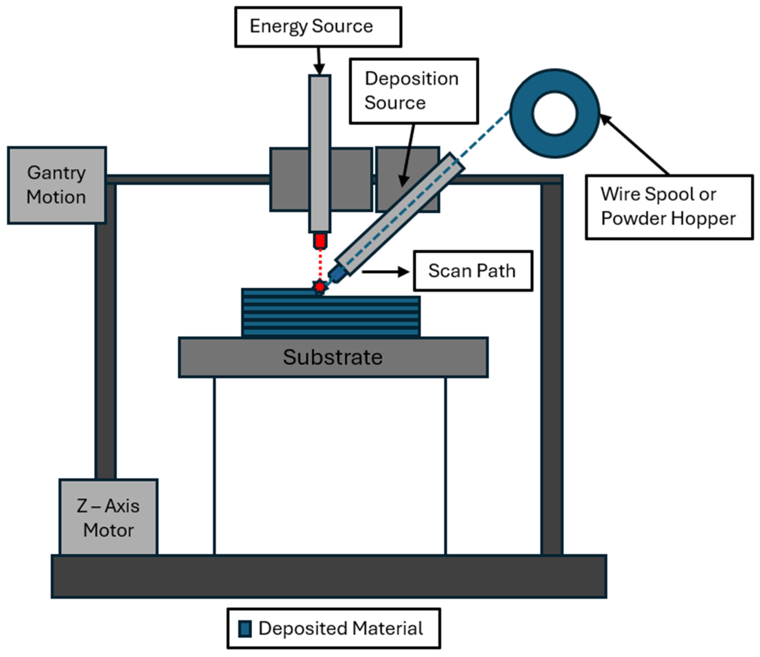
Thermal modeling is an important aspect of simulating the temperature distribution and heat transfer processes in DED. Zhou et al. [
38] developed a quasi-stationary analytical model to determine the melt pool temperature in coaxial printing, a combination of wire and powder fed direct energy deposition. This type of DED reduces porosity by 20% to 30% decrease in the porosity of powder bed parts while at the same time increasing the amount of deposited material. This combination, however, makes the melt pool’s temperature gradient difficult to model, which is an important factor to determine the resulting microstructure and residual stresses in the part.
The analytical model considers thermal energy from the laser and the radiative heat loss of the deposited material with several assumptions, such as constant absorptivity and instantaneous loss of temperature due to material addition. Third, the powder deposition has a Gaussian powder deposition and controlled volume for melting and solidifying metal [
38]. Using superposition, the melt pool’s temperature was determined by Equation (9) and is described in
Figure 1.
where
is the initial temperature,
is the laser energy,
is the heat loss from wire, and
is the heat loss from substrate.
Using the developed model, Zhou et al. [
38] calculated the heat loss for different variations in DED configuration and observed that the combination of powder- and wire-fed DED resulted in a larger melt pool with a higher percentage of fully melted particles and that the changes in powder deposition rate had more of an impact on the melt pool temperature. The calculated error of their analytical model was between 4 and 12.5%.
Ye et al. [
61] focused on the numerical modeling of the thermal behavior of Laser Engineered Net-Shaping (LENS) to optimize the build parameters under high thermal gradients of the LENS process. While significant work focused specifically on the melt pool mechanics overall thermal behavior of the part is unexplored. So, in this work a finite element model is implemented to study the overall thermal response of the system. In this study, the fundamental equations to define heat transfer are characterized by the heat equilibrium equation as follows:
where
is the mass density,
is the rate of change in internal energy,
is the heat flux vector, and
is the heat flux per unit volume. By expressing internal energy in terms of temperature and using finite element approximation, Equation (10) results in the matrix form:
where
In these equations, is the temperature degrees of freedom vector, and represent interpolation functions for nodes n and , is the heat capacity matrix, is the thermal conductivity matrix, and is the external heat load vector.
The only type of heat transfer considered in the model was conduction. The part is treated as adiabatic, which is set to a constant temperature of 323 K. The temperature of the nodes in the laser’s immediate zone during deposition is set to the melting point of the material. Key assumptions include constant material properties, constant melt pool size, and morphology. The temperature distribution for the past step is used as the initial conditions for the next step for transient analysis. The model is discretized into cubic elements with an adaptive mesh near and around the molten pool to capture the thermal gradients.
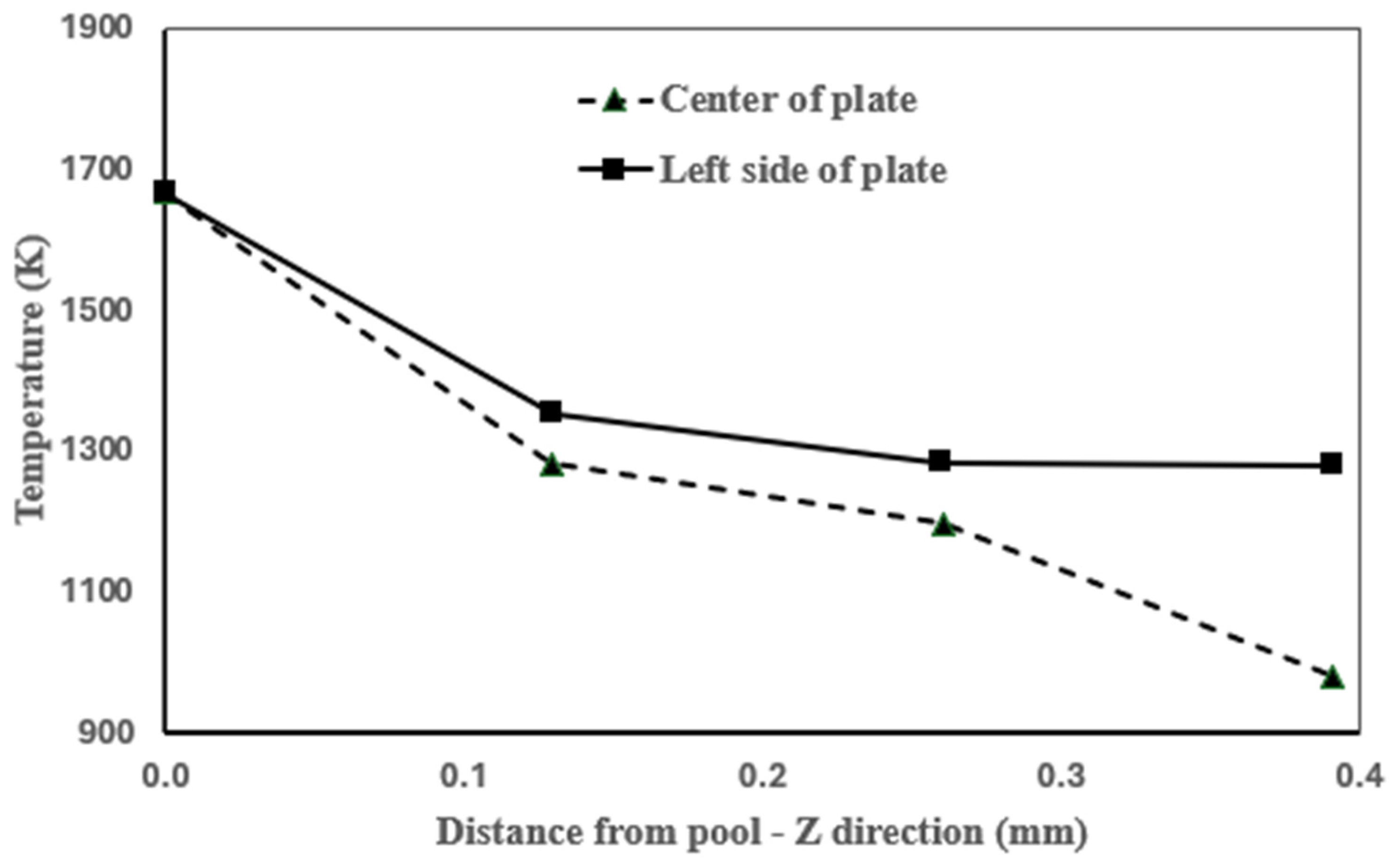
The results of this model, which considered an AISI 316 stainless steel (SS) thin wall, accurately captured the temperature gradients near the molten pool, which were measured to be approximately 588 K/mm, falling within the experimentally observed range of 400–750 K/mm, as shown in
Figure 4. This highlights the model’s ability to provide a precise representation of the heat-affected zone and its influence on the fabricated part.
The model also successfully predicted the rapid temperature drop around the molten pool, where temperatures decreased sharply within 7 mm to stabilize around 529 K. Furthermore, it captured the progressive temperature increase in the fabricated wall as successive layers were deposited, from 529 K at 1.3 mm wall height to 900 K at 2.6 mm, correlating well with experimental trends.
Goffin et al. [
62] worked to characterize the relationship between the shape of the laser beam and the properties of wire-based laser DED in order to optimize the process. They identified two areas of study, namely heat input control with respect to the lasers shape and heat transfer modeling between the laser and the wire and substrate before the melt pool develops. They modeled the heat transfer between the wire and substrate using three different laser shapes and optimized the gaussian distribution of the lasers. For this model, they considered a single pass of a 1.2 kW, 1070 nm wavelength, carbon dioxide laser over a preplaced AISI 316 stainless steel wire, and then validated the results with the optical microscopy to show an improvement in the wetting or melting of the new wire into the melt pool.
The simulations used a Multiphysics package with a specific “heat transfer for solids” plugin by modeling the heat sources as surface heat source of a specific geometry, excluding reflected energy, and neglecting fluid flow and new wire addition. The model considered a 1 mm diameter wire and 35 × 15 × 0.8 mm substrate with the wire and substrate overlapping by a maximum distance of 0.03 mm described in
Figure 5a to avoid errors in the FEA. About 14,900 tetrahedral elements were used with the refinement at the intersection of the wire and the substrate, as shown in
Figure 5b.
The governing equation used for the analysis was the energy conservation equation in Equation (8). The total heat flux of the laser was generated using the COMSOL heat transfer module. The heat flux system considered two different models: direct wire heating (DWH) and direct substrate heating (DSH) to account for the mechanical differences between the two components of the deposition process. The DWH heat flux considered the reflectiveness of the wires profile and then established the absorptivity by taking its inverse and is then mapped onto the surface of the wire. The DSH heat flux is simpler since it is mapped onto a flat surface but must consider the sections of the substrate that are shadowed by the diameter of the wire lying flat on the surface. The setup involved a 1 mm diameter stainless steel wire placed on the substrate material, which was mild steel at 0.8 mm thickness, melted using a 1.2 kW CO2 laser, closely replicating the system considered in the experiment.
The comparison of the model and the experiment demonstrated strong agreement in predicting thermal behavior and melt pool formation during wire-based laser DED. The study highlighted that accurate modeling of heat transfer mechanisms, particularly in differentiating between direct wire heating (DWH) and direct substrate heating (DSH) significantly impact energy absorption and melting efficiency. The results also showed that optimizing the laser beam shape and heat input distribution improves the wetting of the wire into the melt pool, reducing defects and enhancing process stability.
Kiran et al. [
63] developed a numerical simulation to optimize the directed energy deposition process in 316 L stainless to improve the overall part quality and general production health. They modeled the thermal history and stresses of single and multi-pass weld tracks and validated the numerical results with experimental data. Managing the huge amount of data is generally challenging in this process [
59], but they reduced the computational time significantly without sacrificing the accuracy of the model by using thermal cycle heat input combined with a layered element birth approach to create the 3D thermomechanical process. Their thermal model used a laser with a gaussian distribution to simulate the melt pool of the weld, applying the energy balancing equation (Equation (15)) and heat conduction equation (Equation (2)).
where
is the volume of the model,
is the model surface area, and
is the internal heat supplied to the model. These equations were applied to the thermal heat input cycle, treating every track of the weld path as a single block, as described in
Figure 6, using the energy balancing equation to model heat distribution. This approach was compared to a transient model that considers heat input along each individual track per weld, consuming only 5% of the transient model’s computational energy with a minimal loss in the numerical accuracy.
3.3. Thermal Modeling in WAAM
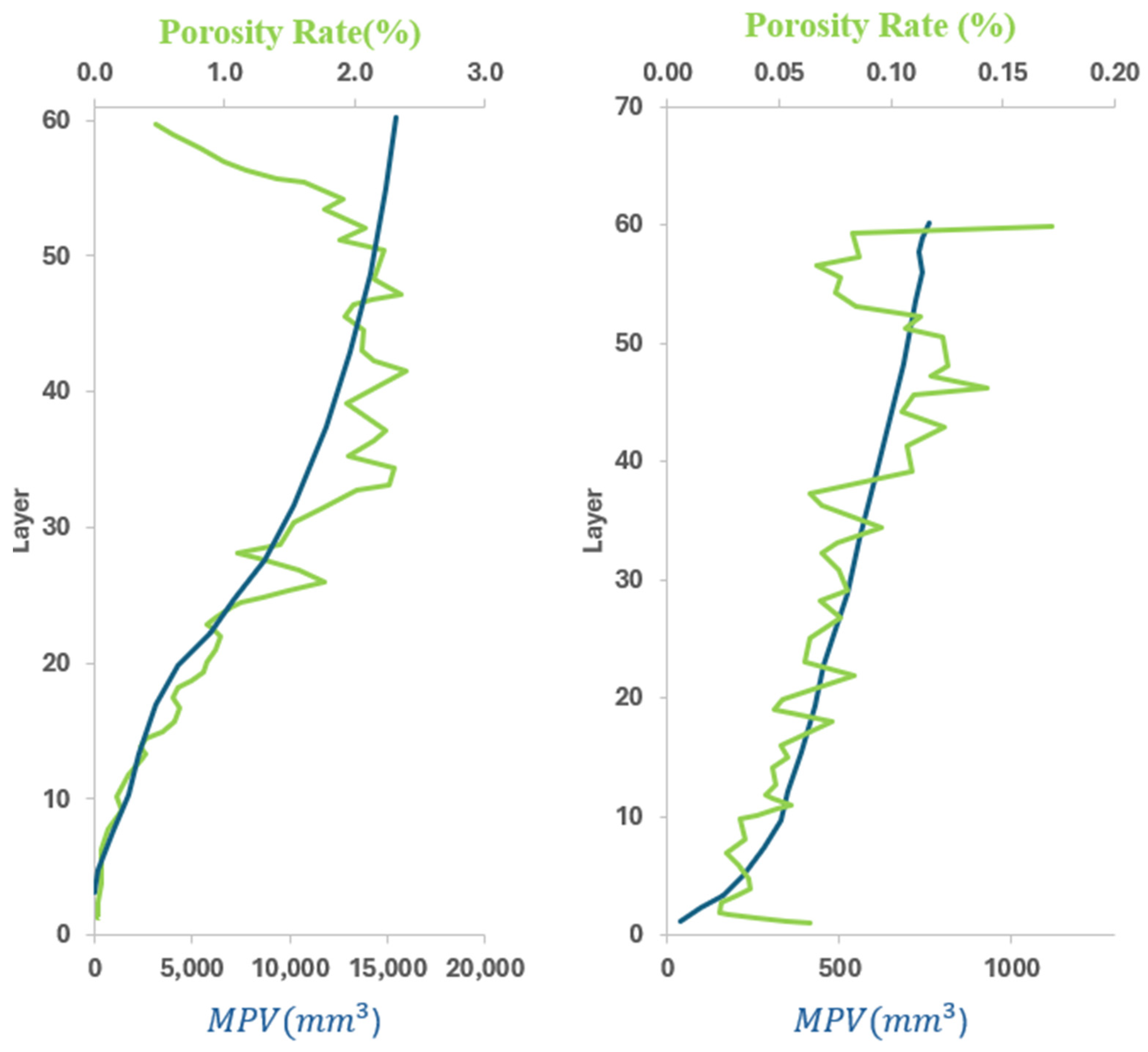
This section considers thermal modeling in WAAM. Beraud et al. [
64] present a simulation-based approach for predicting porosity formation in aluminum WAAM by monitoring the melt pool volume (MPV). In WAAM and other forms of metal, AM porosity reduces the mechanical performance of the part. This study combined thermal simulations with X-ray tomography to establish a relationship between the MPV and porosity. The two primary causes of porosity in aluminum WAAM-fabricated components are shrinkage pores, caused by a reduction in the volume during the cooling phase, and hydrogen trapping during solidification leading to spherical pores. This model uses the heat conduction equation (Equation (8)) to predict the variations in the melt pool volume and the modified Goldak double ellipsoid model that applies 50% of the arc energy to the substrate and the other 50% to the wire feed for deposition of the melt pool. MPV is then calculated by taking a summation of all the elements in a specific time step with temperatures above the melting point shown in
Figure 7.
This model was then validated against experimental results of thin aluminum walls showed that the MPV is directly correlated to the formation of pores with hydrogen trapping accounting for most developed pores. It was also found that long interlayer cooling times allowed for better hydrogen diffusion and reduced porosity. These findings were confirmed using X-ray tomography and suggested that integrating MPV tracking into WAAM process control can optimize cooling strategies, adjust welding parameters, and reduce porosity-related defects, improving the quality and mechanical properties of aluminum WAAM components.
Mishra and Srivastava [
65] present an FEA-based thermal simulation to analyze heat transfer and temperature distribution in aluminum alloy WAAM components. Aluminum’s high thermal conductivity dissipates heat efficiently, leading to reduced thermal accumulation and residual stress formation. However, excessive heat input in WAAM can still lead to distortion and large temperature variations.
The study employs a finite element thermal analysis for aluminum WAAM using ANSYS 2021 R2 to simulate multi-layer deposition. Heat transfer follows the standard conduction equation (Equation (1)). The Goldak double-ellipsoid heat source model (Equation (6)) is applied to represent gas metal arc welding (GMAW) heat input. A “birth and death” element activation technique is used to simulate material addition, ensuring realistic thermal gradients. The thermal simulation framework models a 6061-T6 aluminum substrate with Al 5183 wire deposition, capturing sequential layer heating and cooling effects. A “birth and death” element activation technique is used to simulate material addition, ensuring realistic thermal gradients. A convective cooling coefficient of 5 W/m2 °C is applied to the surface to simulate heat loss. The radiation effect is negligible due to the relatively low temperature of aluminum. The model predicts a maximum molten pool temperature of 437 °C at the topmost layer, with a gradual decrease to 300 °C in the middle layer and 200 °C in lower layers, highlighting aluminum’s high thermal diffusivity and efficient heat conduction. The substrate reached 250 °C, further demonstrating the material’s ability to dissipate heat uniformly. Heat flux values ranged from 0.418 W/mm2 to 2.932 W/mm2, confirming localized heat concentration near the deposition path.
The use of mesh refinement strategies minimized simulation time without compromising accuracy. The temperature profiles obtained from the simulation closely match experimental thermal data from prior studies, confirming the accuracy of Goldak’s heat source model for aluminum WAAM. The findings of this study emphasize that controlling temperature and modifying heat input strategies can significantly reduce residual stress formation and distortion.
Beraud et al. [
66] present a thermal FEA model for WAAM with a focus on reducing the computational cost while maintaining high accuracy in modeling and predicting the thermal behavior of the part. The thermal control challenge of WAAM is well documented with high thermal gradients leading to poor part quality, distortion and residual stress. This model decouples the heat conduction from the convection and radiation, which allows for the parallel computation of these two processes and is designed for quasi-real-time simulation and offline process optimization. This study employed the energy conservation equation (Equation (8)) for heat transfer and Goldak’s double ellipsoid distribution model for the heat source (Equation (6)). The heat conduction was solved analytically using a Gaussian kernel convolution, which smooths and distributes values across a spatial domain as given in Equation (16).
The convective and radiative losses are then computed separately using Equations (17) and (18):
where
is the convective heat transfer coefficient,
is the Stefan–Boltzmann constant, and ε is emissivity.
The model updates material and energy matrices for each step, ensuring conservation of energy while enabling efficient thermal state calculations. The decoupling of the heat transfer processes significantly increased the simulation speed. The Gaussian kernel convolution also reduced computational time and the combination of these two techniques make the simulation 80× faster than conventional FEA simulation. The thermal prediction of this model also closely matched experimental data, making this an ideal approach for process optimization.
3.4. Thermal Modeling in PBF
In this section, we explore thermal modeling in PBF. Roberts et al. [
67] produced a study focusing on the temperature field during the melting portion of a PBF process and simulating the transient temperature history, which is critical for predicting thermal stress distribution and residual stresses. The study of multi-layer interactions is critical because it allows for better process optimization, reducing defects such as cracking, porosity, and warping. This study integrated multiple theoretical frameworks and numerical methods to develop simulation. First, the heat transfer model is employed, starting with the energy balance equation. Next, the heat input model and the conduction are introduced. The heat input model is based on the Gaussian heat source model, as discussed previously, and conduction is modeled using the enthalpy based heat conduction equation applied to isotropic materials [
68] which is defined as
where
is the density,
is enthalpy,
k represents thermal conductivity, and
T represents temperature.
For the physical model, the element birth and death technique are employed to simulate layer-by-layer powder deposition. Material properties are made temperature-dependent, with thermal conductivity varying due to assumed density and the specific heat capacity changing based on the phase of the material. This study provided critical insights into temperature evolution in laser-based AM, allowing for improved process control, defect prevention, and optimization of scanning strategies. It also laid the groundwork for future studies on residual stress prediction and microstructural development.
Rizza et al. [
69] presented a new methodology to evaluate the thermal conductivity of a powder bed based on the solid material packaging structure. The Representative Elementary Volume (REV) used was a Body Centered Cubit element (BCC). The thermal conductivity could be evaluated as a function of thermal diffusivity of the powder as
where
is the thermal diffusivity of the powder material,
represents the density of the powder bed, and
is the specific heat capacity of the powder bed [
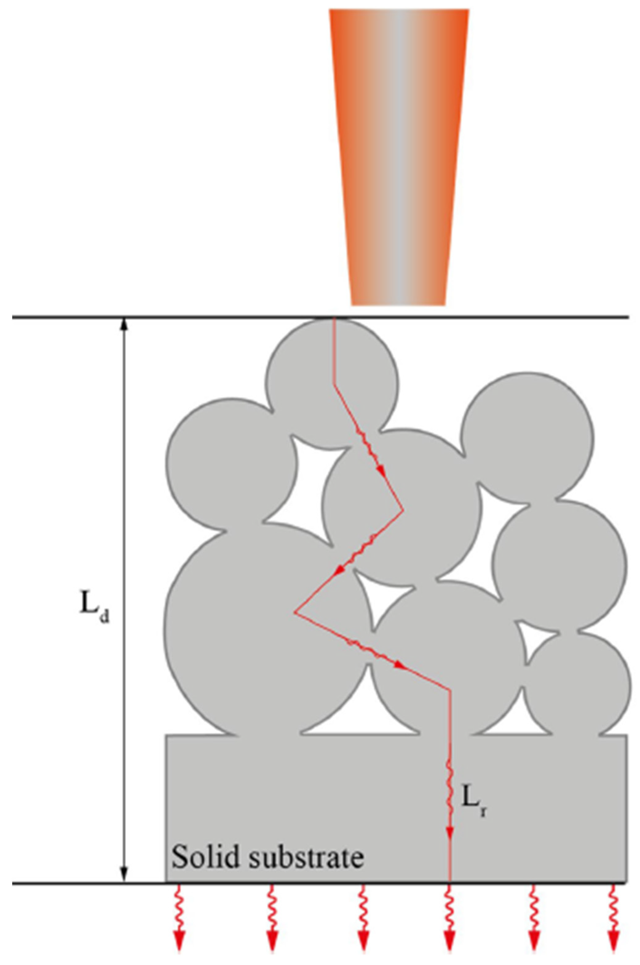
69].
Figure 8 shows an ideal path of thermal conductivity applied to a 2D section of a powder bed composed of random distributed particles where the fusion between particles has already begun. The red line represents one of the possible trajectories of the heat flow.
Ahmadi et al. [
56] proposed a formula in which the path of the heat flow is calculated by considering only the geometrical characteristics of the material. Equation (21) shows the heat flow of fluids within voids at a macroscopic scale.
where
represents the effective thermal diffusivity,
n is the void fraction of the material,
is the particle diameter,
represents the fluid temperature and
is the characteristic length for the thermal boundary layer.
In addition to this equation, data relating to the powder characteristics and information about the geometry are necessary to obtain the thermal conductivity [
69].
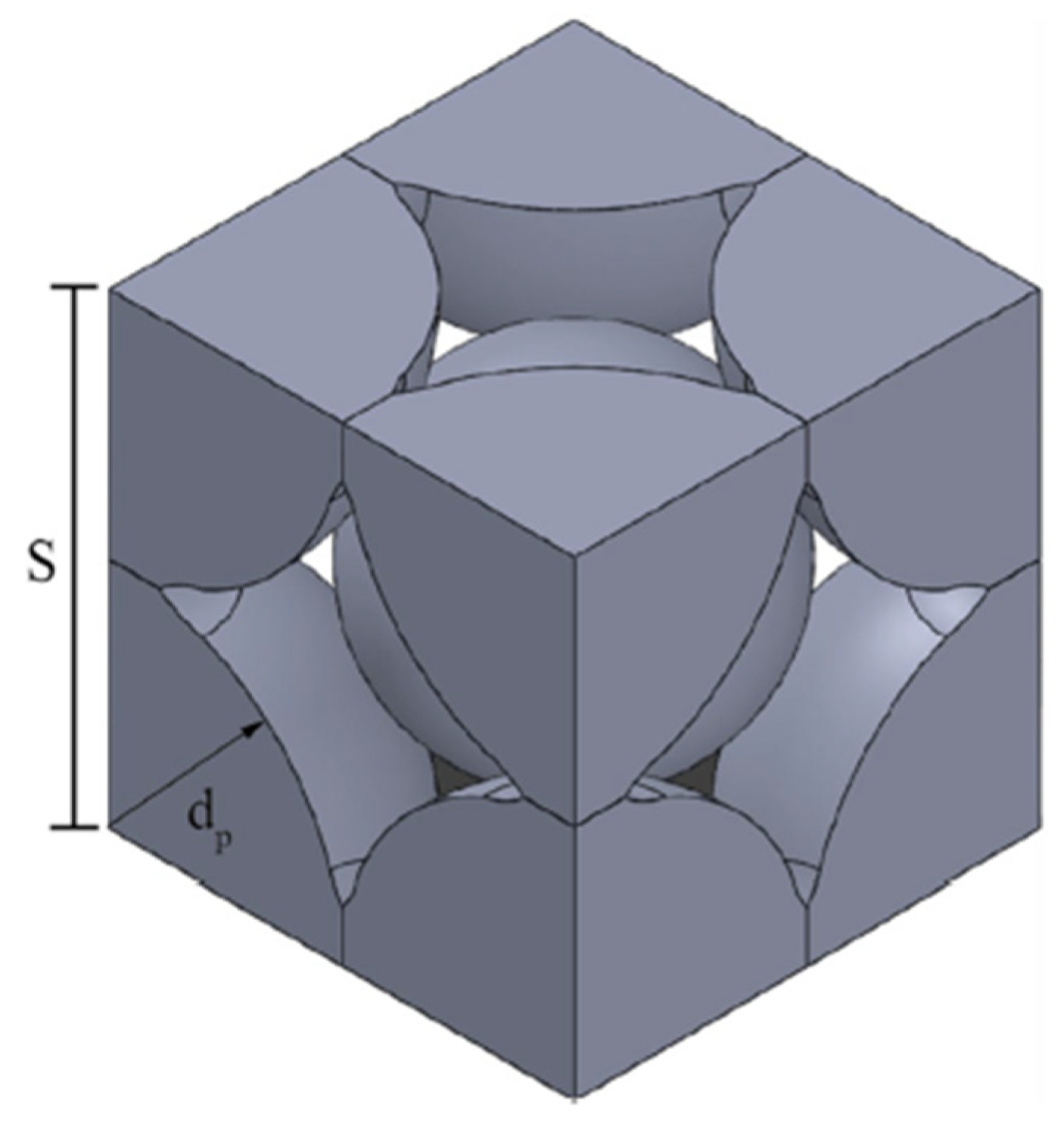
Figure 9 shows the BCC structure considered for the calculations. The diameter of the eight particles at the edges was considered constant at 80 µm, and the center particle was 58.6 µm. These values are inside the typical range of PBF particles size. The temperature simulation varied from 879 to 1273 K.
This methodology was designed for the powder bed fusion with electron beam (PBF-EB) process, but it could be applicable to all the powder beds. In addition, future work should include densification of the packaging structure [
69].
Lough et al. [
70] present a data-driven thermal modeling approach for laser-based PBF using a Discrete Green’s Function (DGF) superposition model shown below in
Figure 10. The main objective is to develop better real time thermal predictions for better process control and defect mitigation. In this work, short-wave infrared thermography (SWIR) was used to construct the DGF predict the thermal history of the melt pool in the powder bed. This approach minimizes computational cost compared to other traditional FEM and CFD models while maintaining high accuracy.
The DGF describes the system’s thermal response to a laser pulse applied to the powder bed, which is recorded using SWIR imaging to capture the temperature decay due to conduction and convective heat transfer mechanisms. The recorded response is then normalized and stored, and by superimposing the DGFs of successive laser scans, the full-layer thermal history can be reconstructed with high accuracy. The governing equation for this superposition-based thermal model (Equation (22)) is given below:
where
is the temperature at position (
,
) and time
,
is the initial temperature of the substrate or powder bed,
is the DGF response at distance rₖ and time delay
and
is the number of past laser interactions contributing to the thermal field.
This strategy effectively captures conduction and convection effects and accurately predicted temperature within 8% compared to thermographic measurements and stays consistent across the different parameters chosen.
This study provided fast, accurate thermal history predictions for LPBF, enhanced real-time process control and offers a viable alternative to computationally expensive thermal models.
Soundararajan et al. [
71] presents a mesoscale finite element thermal model for laser powder bed fusion (LPBF), specifically analyzing heat transfer mechanisms in shallow beds of polyamide powders. The main objective is to develop a high-fidelity heat transfer model incorporating temperature-dependent material properties and validate it using a three-dimensional experimental setup that captures both top-view and bottom-view thermal data, providing direct validation of laser absorption, melt pool dynamics, and cooling behavior.
The FE-based thermal model considers heat conduction, convective dissipation, and radiative heat losses, and phase change dynamics for melting and solidification. The authors employ Beer–Lambert’s law given by the equation below (Equation (23)) to model laser energy absorption within the powder bed.
where
is the intensity of laser energy at depth
,
is the incident laser intensity at the surface, μ is the absorption coefficient, and
is the depth within the powder bed.
The absorbed heat flux is defined as
where
is the absorptivity of the polyamide powder,
is the laser power,
is the beam radius, and
is a time-dependent laser function
This formulation captures both the Gaussian beam profile in the XY-plane and the depth-dependent attenuation in the Z-direction, offering a more realistic representation of energy input.
The model accurately predicts temperature evolution and heat penetration depth, with an average error of less than 10%. When compared to conventional FEM-based thermal simulations, the Beer–Lambert-based model provides equally accurate predictions while significantly reducing computational cost, making it a strong alternative for real-time thermal modeling in LPBF.
3.5. Finite Element Analysis (FEA) Approaches
Thermomechanical simulations in metal AM can be handled using either sequentially coupled or fully coupled models. A sequentially coupled model solves the thermal problem first, using temperature distributions as input for the mechanical analysis. This approach assumes that the mechanical response does not significantly affect the thermal field, making it suitable for problems where thermal effects dominate, such as slow-heating processes or cases where material expansion is minimal. The main advantage of this method is its computational efficiency, as it simplifies the numerical solution process by decoupling the two fields.
A fully coupled thermomechanical model, on the other hand, solves the thermal and mechanical equations simultaneously, capturing interactions such as deformation-induced heating and temperature-dependent material properties [
72]. This is essential for processes where heat generation from mechanical work, phase changes, or high strain rates significantly influence both temperature and stress fields. Applications such as welding, additive manufacturing, and high-speed machining require fully coupled models for accurate predictions. However, these models demand more computational resources and robust numerical solvers to handle complex, interdependent physics. The choice between sequential and fully coupled modeling depends on the level of interaction between thermal and mechanical effects in each problem.
Element types and meshing strategies in metal AM must account for layer-by-layer material deposition and localized heat input. Tetrahedral and hexahedral meshes are used to capture thermal gradients, residual stresses, and distortions, with higher-order elements improving accuracy in steep temperature changes. Structured meshes offer precision but struggle with complex geometries, while unstructured meshes adapt better but may introduce numerical errors. Adaptive meshing refines elements based on localized heat flux and mechanical stress, optimizing computational efficiency.
Metal AM FEA techniques must capture thermomechanical interactions, phase changes, and material evolution. Element birth and death methods activate elements progressively to simulate material deposition, while quiet elements represent un-melted powder with low stiffness until solidified. Reduced integration elements prevent numerical locking in high-temperature simulations, and mesh coarsening reduces computational load in non-critical regions. These techniques accurately predict thermal distortions, residual stresses, and final part integrity while balancing computational efficiency with accuracy.
3.6. Numerical and Thermo-Mechanical Modeling in DED
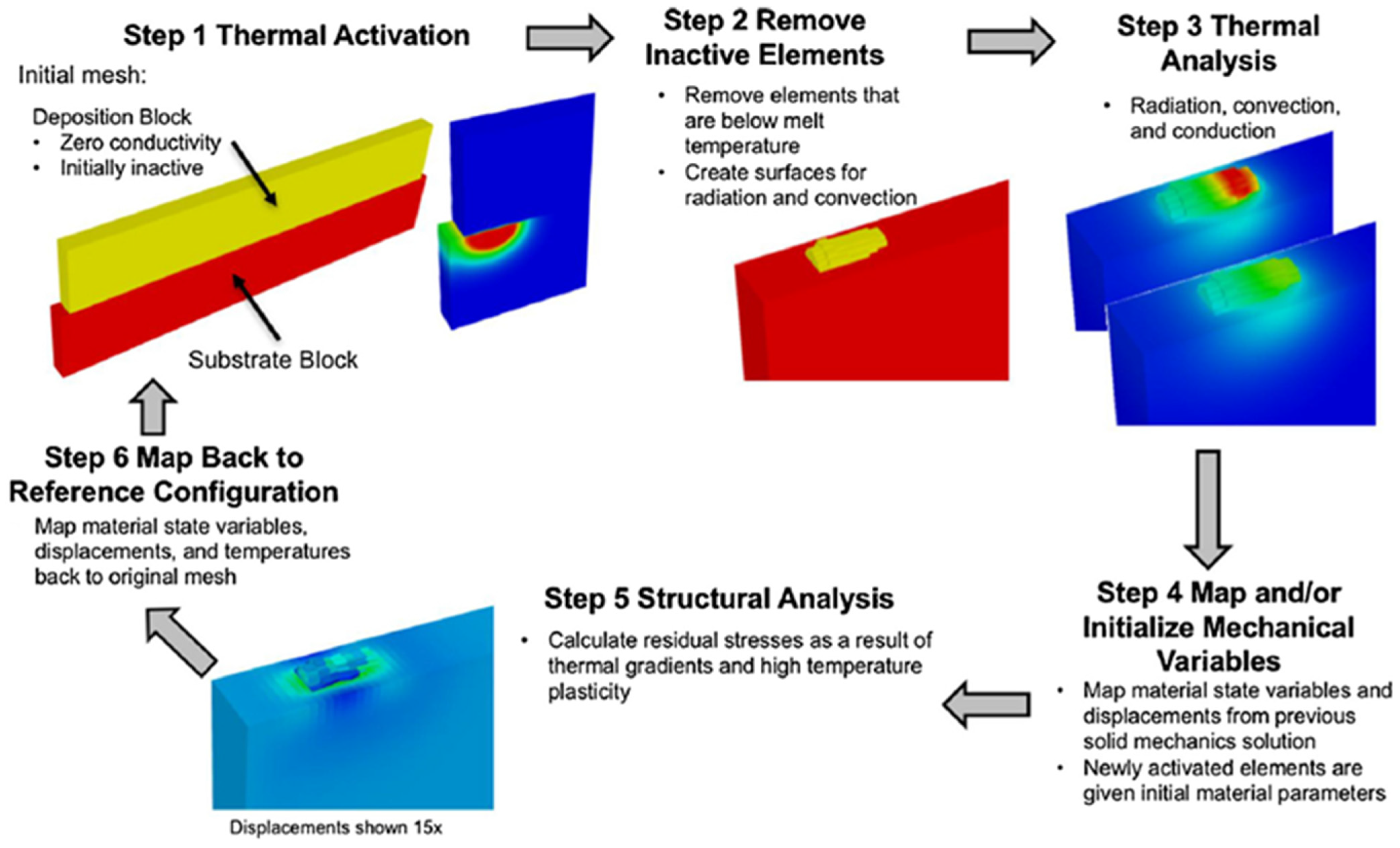
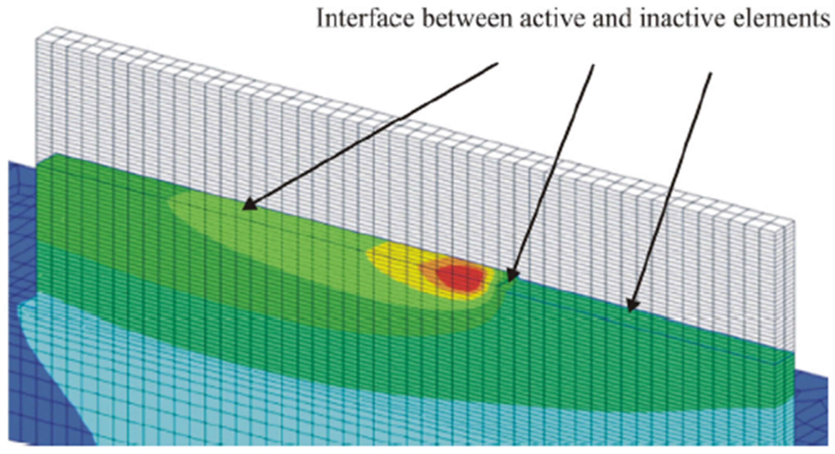
Stender et al. [
37] developed a complex multi-step finite analysis element workflow to predict the properties of a 304L stainless steel part built using DED, more specifically laser engineered net shaping (LENS). Since, in LENS, each layer is reheated multiple times, it is critical to consider the influx of heat into the whole part after each layer as this will affect the microstructure, residual stresses, and total deformation during the build process. This differs from other FEA for DED because it considers a larger macroscale model to keep computational cost low and does not use quiet elements to connect different domains [
73]. Instead, elements whose behavior is based on a certain temperature threshold were used.
Figure 11 shows the finite element workflow steps involving the thermal input and activation, removal of inactive elements, and thermal analysis. After these steps, the thermal analysis results are transferred to a mechanical model for a structural analysis, which is then mapped back to the original mesh, repeating the process repeats.
Once the temperature history of a layer is modeled, those data are transferred to a mechanical model. The properties of elements are determined by their temperature; they are solid properties below the melting point and Newtonian fluid properties above the melting point.
As the elements cool and resolidify, recrystallization is modeled to determine residual stresses and deformations that occurred during this step. Once prior steps have been completed, the data from previous layers are mapped to the original mesh and the process begins again for the next layer. Using this method, Stender et al. [
37] accurately predict residual stresses, deformations, and temperatures when compared with experimental results.
Kiran et al. [
28] investigated two different heat source models in metal AM and their agreement with experimental results. They compared a concentrated heat source model with the Goldak heat source model, which is widely used in the modeling of DED for simulating the deposition of 316 L Stainless Steel in both a simple single-track build as well as a more complex 3D part to study the effects on residual stresses. The Goldak model uses a double ellipsoid heat source distribution which represents the melt pool, or molten region of the deposition process. This considers various parameters which define the weld pool dimensions, meaning that the melt pool characteristics for different parameters must be experimentally validated making this process expensive and impractical. To mitigate this, studies have modeled the heat source on a layer-by-layer basis by adding heat flux to a single layer instead of following the real path of the deposition. This, however, results in error, as it ignores the cooling of the part following the localized heating of the new deposition. Kiran et al. [
28] instead employed a general transient heat source that, unlike the Goldak model, does not require different parameters to define its state in different modes but can be applied directly to the deposition.
The mechanical model used DC3D6 and DC3D8 elements and utilized element activation to simulate deposition of material. Boundary conditions considered only surface elements, which are constantly evolving during the process, as undergoing heat loss. This thermo-mechanical model was then validated against experimental results, showing that the simple heat source model significantly reduces the complexity of this type of analysis with a precision of about 87%. This application also reduced the computational time by roughly half while closely matching the Goldak model’s results.
Michaleris [
70] studied finite element models for different deposition and heat transfer processes in laser and electron beam printing, focusing on the different approaches used to model deposition. Specifically, the application of quiet elements or element deletion.
Quiet elements are elements that exist actively in the model with given properties that will not affect the rest of the model until material is “deposited”. This approach is easily applied to commercial FEA software using user defined materials, commonly referred to as UMAT [
40]. Because the number of elements in the model is constant during the analysis, complicated processes, such as the renumbering of equations and solver initiation, are not required. However, if the scaling factors used to reduce their properties to a negligible level are not low enough, they can introduce error. Also, maintaining all the elements for the entire analysis can lead to long computational time.
Inactive elements are shown below in
Figure 12. Alongside the active elements, there are elements that already have the correct material properties but remained “off” until they are turned on and behave normally. This approach prevents introducing error into the model because only active elements are considered at any time and reduces the computation cost. However, this approach cannot easily be applied to commercial FEA software, since the introduction of new nodes and elements equations must be renumbered and a solver initialization must be run for each new element. Moreover, whenever new elements share a node with an existing element that has some temperature value, the new elements node will share that temperature introducing extra energy into the model.
Michaleris studied how these approaches compare when used to model a simple, single-pass, wall build, and found that both systems result in an artificial heating of the model of nearly 5% during the “deposition” of an element. To combine the advantages of both, a hybrid approach is proposed: starting with inactive elements that shift to a quiet element format at each layer, with their material properties changing during the deposition of material in the model. This reduces initial model minimalization, limits equations renumbering, and reinitializes the solver once per layer instead of per element, thereby reducing the computational run time of the analysis.
3.7. Numerical and Thermo-Mechanical Modeling in WAAM
Lundbach and Lindgren [
75] developed and validated a numerical model for wire fed tungsten arc metal deposition (MD) in FEA to address the challenges of simulating complex metal deposition processes, which are very similar to multi-pass welding. This project developed computational tools used to predict distortions, residual stress, and thermal behavior in the metal AM process while reducing the expensive and time-consuming process of the experimental approach to developing build parameters, reducing waste, and producing quality parts.
The FEA model consisted of 13,000 hexahedral elements and employed Goldak’s double ellipsoid heat source to approximate energy input from the tungsten arc. The deposition process was simulated using element activation, the elements were thermally activated when heated by the heat source, and the mechanical properties were updated upon cooling.
The model was calibrated on a single-wall geometry and validated against experimental data using a 10-layer build with four weld passes per layer, as shown in
Figure 13. The results showed strong agreement between the simulated and the measured temperatures. The deformation predictions aligned well with the experimental data in early layers, although discrepancies emerged in later layers due to fixture rigidity assumption. The study also demonstrated the impact of weld sequence and cooling times on thermal gradients and residual stresses.
Integrating element activation methods, simplified heat input models, and automated weld path generation reduced computational complexity while maintaining accuracy.
Ding et al. [
46] presented a thermos-mechanical analysis of the WAAM process for large scale components with high deposition rates to understand temperature distribution, residual stress and distortion in multilayer WAAM components. In WAAM, high heat input into the part from the arc creates high temperature gradient and leads to residual stresses and large deformations. Therefore, it is essential to predict these issues in order to optimize process parameters and reduce defects. To efficiently model this behavior, a steady state thermal analysis is integrated with a mechanical stress prediction model and then two different approaches are considered. First, a transient thermos-mechanical model, and second, a steady state thermal model mapped to a mechanical model.
The heat transfer model used the governing heat equation and Goldak double ellipsoid model to simulate heat input and transfer in the simulation.
The mechanical model considers an elastic–plastic model and the stress strain relationship defined by Hooke’s law. The model utilizes the element birth technique for material deposition. The substrate was fixed in the model to simulate clamping during the deposition and unclamped afterwards to analyze stress redistribution.
This model was then validated against mild steel walls using thermocouples for validation of temperature profiles, Neutron diffraction measurements for residual stress validation, and laser scanning for distortion. Both the transient and steady state models accurately predict the mechanical behavior. However, the steady state approach reduced computational time by nearly 80%, making it more efficient especially for large scale components and analysis. The residual stress analysis revealed uniform distribution across the layers and stress redistribution lead to lower stresses in higher layers and significant bending. This study developed an efficient thermo-mechanical FEM model for large-scale WAAM. The approach provides a valuable tool for process optimization, allowing manufacturers to minimize residual stress and distortion while maintaining high deposition rates.
Montevecchi et al. [
47] developed a finite element modeling approach to simulate the WAAM process focusing on thermal effects, residual stress, and part deformation. Residual stress and large deformations after printing are major issues facing WAAM. This study developed a modified heat source model which accounts for the energy distribution between the deposition material and the substrate.
This thermo-mechanical finite element model simulates heat transfer, material deposition, and mechanical stress. For the heat source, two models were considered, namely the standard Goldak double ellipsoid model and a modified approach developed in this study. The Goldak model has been found to overestimate the melt pool temperature and distortion predictions. To mitigate this, the modified heat source splits the heat input into filler and base material components equally and uses the Goldak model for heat input into the substrate but applies a constant heat flux for the deposition material as follows:
where
is heat input to the filler material and
is heat input to the base material.
Element activation is used to simulate material deposition, and the part is considered clamped during deposition and unclamped after cooling. An elastic-plastic model used the yield stress that follows a temperature dependent flow law given by Equation (26):
where
is the initial yield stress and
is thermal softening coefficient. The modified Goldak model improved accuracy by properly distributing the energy into the substrate and deposition material, which allows process optimization, reducing experimental trial-and-error, and improving WAAM component quality.
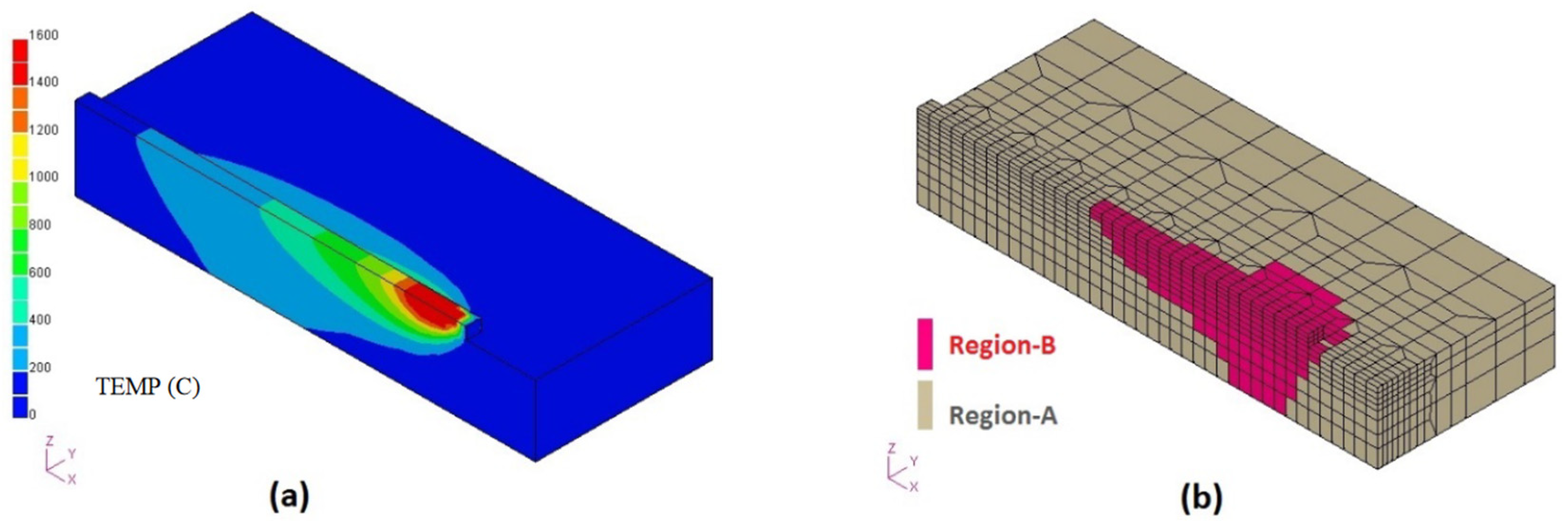
Huang et al. [
76] in this research consider a high fidelity simulation approach to predict residual stress and distortion in large scale WAAM parts. As discussed before, due to the high heat input and rapid cooling, the part experiences thermal stresses which cause warping and residual stress. Traditional FEM struggles with these large simulations due to the high computational cost. To mitigate this issue, they considered three different advanced computational acceleration techniques; Iterative Substructure Method (ISM), Dynamic Mesh Refining Method (DMRM), and GPU-based Explicit Finite Element Method.
The ISM technique functions by dividing the simulation domain into linear and nonlinear regions (as shown in
Figure 14b), with linear characteristics representing elements above a certain distance from the melt pool and nonlinear representing elements below a certain distance. This reduces global iterations and increases the speed of simulation by three times. DMRM dynamically refines the mesh near the heat source to focus computational power. This reduces the number of elements of the total model without sacrificing accuracy near the melt pool and achieves an increase in computational speed of 9×. The GPU-Based Explicit FEM uses parallel computing on GPU hardware to accelerate stress analysis and utilizes time scaling techniques based on inherent strain theory to speed up time integration. This method provided the biggest increase in computational speed of 30× to 70× making it the most feasible for large scale WAAM simulations.
The results of these models were all validated against experimental results with less than 10% error in the residual stress predictions. This demonstrates that high-performance computing techniques can make real-time WAAM simulations feasible, allowing manufacturers to optimize process parameters, minimize defects, and improve part quality.
3.8. Numerical and Thermo-Mechanical Modeling in PBF
Li et al. [
35] developed a model to efficiently predict part distortion in Selective Laser Melting (SLM), addressing the challenges posed by continuous reheating and cooling during layer-wise deposition. Predicting thermal gradients, residual stresses, and distortions is computationally expensive, as each layer interacts with the previous ones, requiring detailed thermal–mechanical modeling. To overcome this, the study employed a three-part multi-scale simulation. First, a micro-scale model captures the heat input and melt pool dynamics. This is then mapped to a meso-scale model, which determines the residual stresses, and finally, a macro-scale model predicts the resulting part distortion.
The heat transfer model accounts for conduction into the powder bed and build plate, along with radiation and convection losses. To reduce computational cost, the study introduces an equivalent heat source approach, which replaces direct simulation of every laser scan with a representative heat input, significantly reducing the number of calculations while preserving accuracy. Validation against experimental data showed strong agreement in thermal history, residual stresses, and distortions. The study found that sequential scanning strategies resulted in lower distortion, while crosswise scan paths induced higher residual stresses. Additionally, compressive stresses formed in upper layers, while tensile stresses accumulated in lower layers, leading to part distortion. This multi-scale approach provides an effective tool for optimizing SLM process parameters while minimizing computational cost and reliance on experimental testing.
Masoomi et al. [
77] performed a numerical simulation using the COMSOL 4.4 Multiphysics finite element software. Three assumptions were made: powder bed is homogeneous and continuous; laser heat possesses a Gaussian intensity distribution and thermal conductivity is dependent on the gas filled chamber. The objective of this experiment was to measure the sintering surface temperature using thermocouples. Laser power and scan speed were parameters recorded due to the strong influence on temperature gradient.
Powder bed characteristics and thermal conductivity have an important influence on the quality of parts manufactured [
55,
78]. One of the main factors that influences thermal conductivity is the powder particles packaging structure. In PBF, the powder size ranges between 45 and 105 µm. This difference in size creates a disordered packaging structure that makes the evaluation of the thermal conductivity over the powder bed a complex activity. Moreover, determining the thermal conductivity of a powder bed requires a study of the heat transfer process [
69].
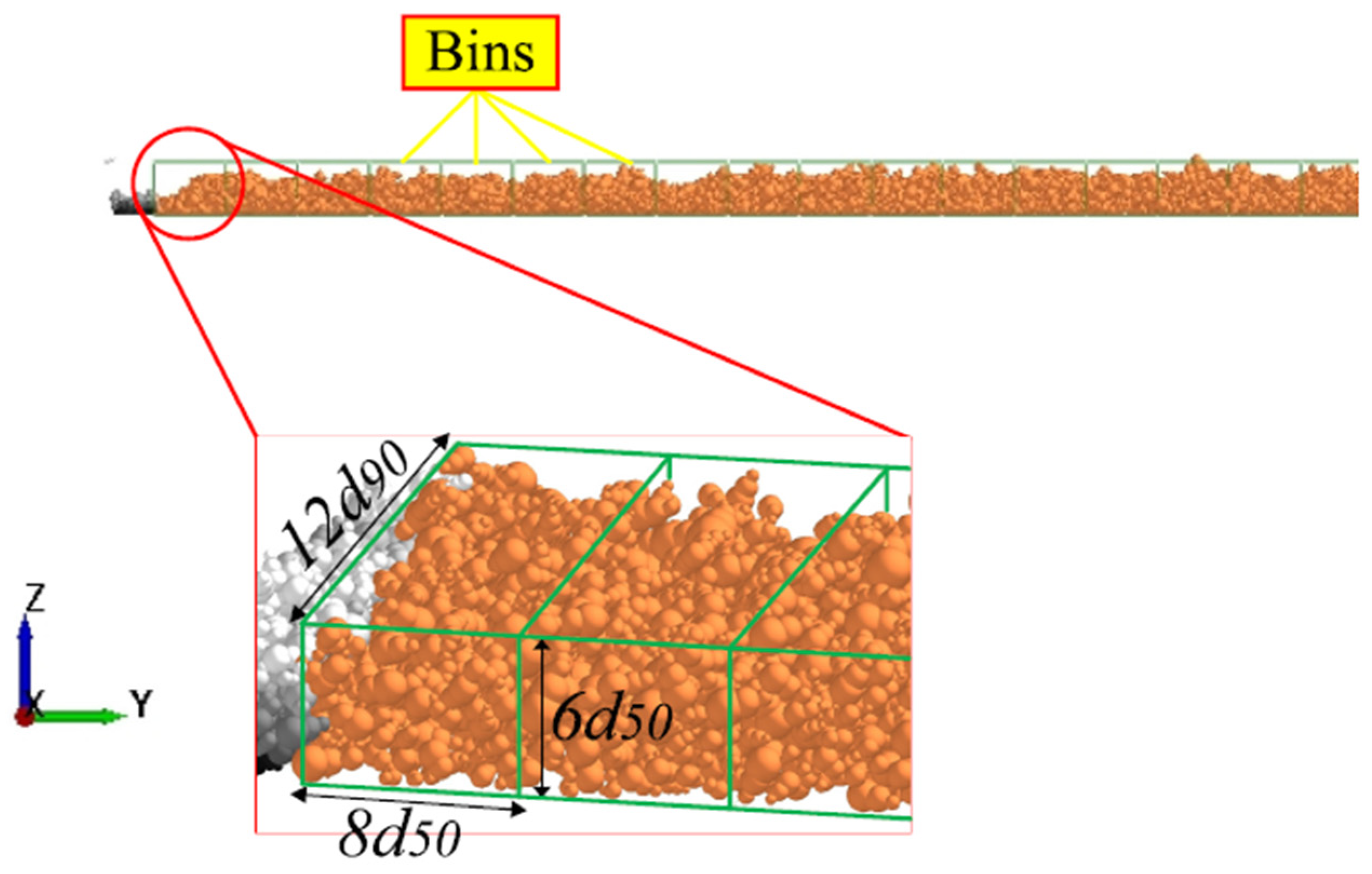
Zinatlou et al. [
79] studied polyamide 6 (PA6) particles from SINTERLINE
® using a scanning electron microscopy (SEM) to measure characteristics of the particles. The authors classified the particles according to their shape (spherical, elongated or other). The interfacial surface energy between particles was calculated using the pull off force, which is the maximum tensile force required to overcome and break the contact between particles measured as follows:
where
represents the surface energy, and
is the effective radius of contact between the two particles.
Experimental surface energy values were compared with surface energy using the cohesion number (Coh) between particles within the computational model calculated by Equation (28):
where
represents the density,
is the gravitational constant, and
is the effective elastic modulus of the particles.
The simulation was performed in EDEM 2022 (Altair) using the Johnson Kendall Roberts and Hertz Mindlin model to describe forces in contact. All the information in the simulation was scaled up 43 times the real values. To assess the quality of the power bed, the analysis was separated by bins, as shown in
Figure 15 [
79].
The packing fraction of the powder bed was determined as follows:
Figure 16 shows the shear stress value calculated from the simulation for different shape particles, which were compared with the theoretical results. These results demonstrate the influence of the powder shape over the shear stress.
Figure 17 shows that both temperature and speed affect the average shear stress similarly. In addition, at elevated temperatures, there is an increase in the cohesion of the particles.
One of the most important components of developing accurate PBF additive manufacturing models is the simulation of the melt pool. This is a complex issue, as it involves many moving parts such as the physical structure of the deposited material (whether it is a powder or wire) and the power of the energy source (either EBM or SLM). Galati et al. [
80] developed a novel model that focuses on the thermal–mechanical analysis of powder bed fusion using an electron beam microscope. This was carried out by developing subroutines that analyze the melt pool and the change in the powder’s mechanical properties as functions of temperature and time.
The approach for the modeling of the powder focused on the effects of the EBM on the powdered material. While some researchers, such as Korner [
81], modeled the particles as individual entities and examined all their interactions, others treated them a continuum to simplify the finite element model. Galati et al.’s [
78] approach was the latter, treating the powder bed as isotropic with a given porosity. In contrast, modeling individual particles requires consideration of every sintered connection and reaction between the particles.
With the powder bed structure established, they used the Tolochko model [
82] to simulate the thermal conductivity. This model, experimentally developed by Tolochko et al. [
82], characterized the heat transfer in titanium powders from different laser parameters in selective laser sintering (SLS):
where
is the thermal conductivity from the radiation and
is the conductivity due to the physical connections of the necking between powder particles.
Emissivity was modeled after the work of Sih and Barlow [
83], considering the combined emissivity from the particles and voids in the powder bed:
where
AH is the surface fraction of the voids in the surface,
is the emissivity of voids, and
is the emissivity of the material.
The electron beam transfers energy to the surface of the powder bed by bombarding it with electrons whose kinetic energy is then converted into thermal energy. Monte Carlo simulations showed that the electron beam rapidly lost energy, as it penetrated the surface of the powder. Therefore, energy transfer from the electron beam can be neglected for layers beneath the top surface, and subsequent layers could consider simple conduction for heat transfer.
Pourabdollah et al. [
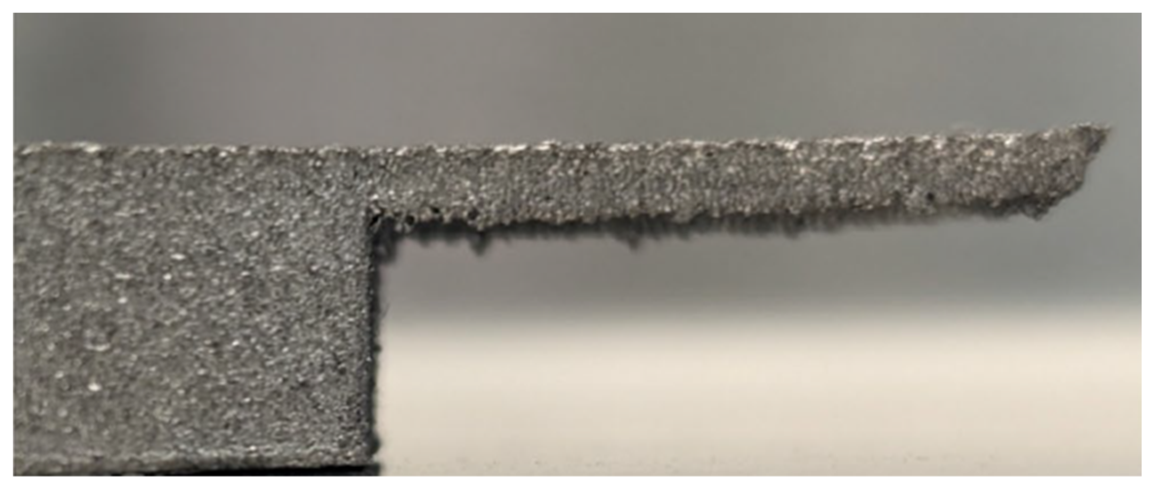
84] developed a coupled thermomechanical model in FEA software Abaqus, where thermal analysis affects stress analysis, but not vice versa. In this work, the authors justified that the “side loss” defect [
82], shown in
Figure 18, at the free end of the overhang platform is attributed to the cooling effect between successive melted layers, reducing layer length.
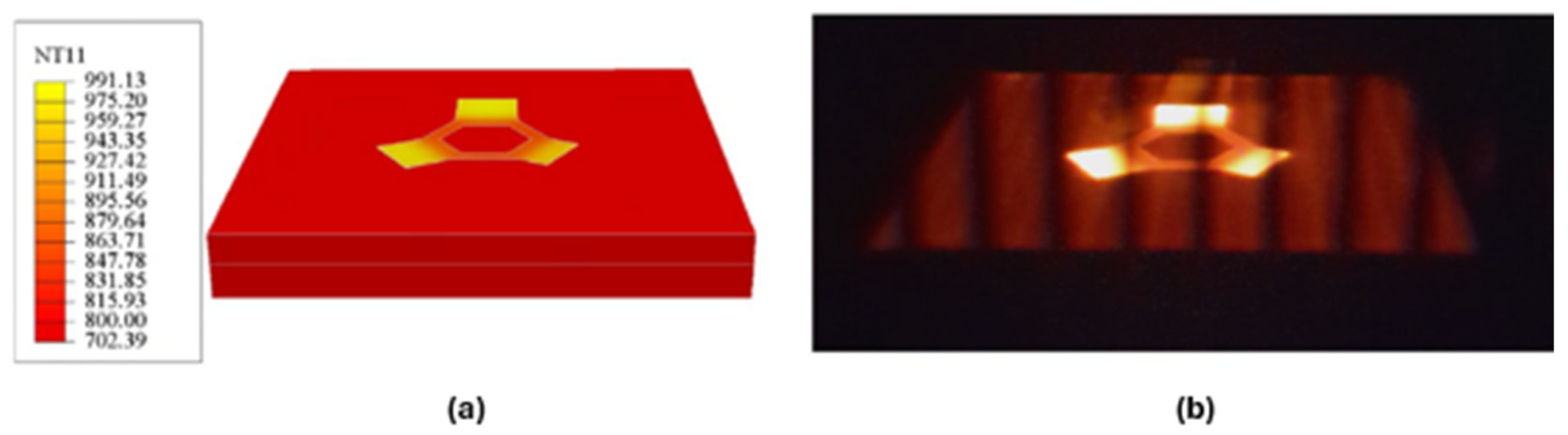
In the electron beam PBF process, heat loss occurs via radiation from the top surface and conduction through the material and the powder bed. Radiation and convection were considered for heat losses to the surrounding environment. A time-averaged volumetric heat input was applied to the top layer after activation, where beam energy for preheating and melting was calculated per powder layer. To analyze the mechanical properties of the model and plastic strain, an initial thermal strain was added for each computational layer. The stress equilibrium equation and mechanical constitutive law, considering the total strain tensor decomposed of three strain terms, elastic, plastic, and thermal, are applied. Plastic strain was determined using the von Mises yield criterion and the Prandtl–Reuss flow rules. For the mechanical boundary conditions, the bottom surface of the start model was constrained in the direction, and the two diagonal corners were additionally constrained in the x and z direction.
The temperature results were compared to a picture taken from an ARCAM Q20 camera after processing the last layer
Figure 19 showed that there is acceptance between the temperature distribution of the model and the experiment.
The plastic strain results showed that without inherent strains in the base and overhang layers, the model predicted virtually no distortion. The layer glomeration approach with flash heat avoids melt pool formation or large temperature gradients but capture thermal field evolution as well as thermal stresses associated with macroscale temperature gradients and the thermal expansion mismatch between materials. An iterative process of plastic strains with compressive plastic strain of −0.01112 and −0.0008 applied in the simulation matched physical measurements.
Figure 20 shows the predicted vertical displacements including thermal contraction and permanent displacements associated with plastic deformation. The hexagonal base shows zero displacement, which is consistent with the bottom constraints. The top of the base shows downward displacement consistent with thermal contraction dominating the overall displacement, while the two longer overhang platforms show a net upward displacement (warping), which is consistent with the results of the compressive plastic distortion dominating over thermal contraction.
4. Coupled Material Flow and Fluid Dynamics in Metal AM
4.1. Marangoni Flow and Surface Tension Effects
Material flow dynamics play a crucial role in additive manufacturing (AM), as fluid convection and surface tension effects influence melt pool shape, penetration depth, and defect formation [
10]. Proper modeling of these dynamics ensures accurate predictions of bead geometry [
85], lack-of-fusion defects, and keyhole porosity formation, all of which affect the final part quality. The physics governing material flow in AM are well defined by the Navier–Stokes equations, which describe fluid motion, and Marangoni flow, which captures the effects of surface tension-driven convection [
86].
Marangoni flow arises due to surface tension gradients in the liquid melt pool and drives molten material from low to high surface tension regions. This effect, primarily caused by temperature gradients, significantly influences melt pool convection, bead shape, and defect formation. Strong Marangoni flow enhances material mixing and creates a more uniform melt pool, whereas weak Marangoni flow can contribute to instability and defect formation [
87]. It can be mathematically defined by the following equation (Equation (32)):
where
is the surface-driven force due to variations in surface tension,
is the surface tension,
is the rate of change in surface tension with respect to temperature, and
is the temperature gradient in the melt pool. Understanding and controlling Marangoni flow is essential for optimizing process parameters and minimizing defects in AM.
4.2. Material Flow in DED
In Directed Energy Deposition (DED), material flow behavior plays a crucial role in determining the final part quality and mechanical properties. Unlike PBF, which operates in a static powder bed, DED involves continuous material deposition, where the interaction between heat input, material feed rate, and molten pool dynamics governs the morphology of the deposited layer. This introduces unique challenges, such as uncontrolled melt pool flow, material spattering, and surface roughness, all of which impact the final geometry and structural integrity of the printed component.
To accurately predict thermal gradients, residual stresses, and deformation, FEA models must incorporate material flow characteristics, including heat transfer, viscosity, and phase transitions. Flow dynamics influences how energy is absorbed and distributed, affecting solidification rates and microstructural evolution. Advanced fluid–structure interaction models and coupled thermal–mechanical simulations are often used in DED to enhance predictive capabilities, allowing for better control of melt pool stability and part consistency.
Zhao et al. [
88] present a multi-phase flow model for a DED process. The goal for this research was to improve traditional modeling by utilizing a signed distance function-based interface capturing method to track dynamic interfaces. While most deposition models use a predefined deposit shape, this technique derives the geometry of the deposition by using energy minimization principle and mass conservation constraints, enabling simulation of the gas–liquid-solid interactions, melt pool behavior and heat transfer dynamics while reducing computational cost.
For the fluid flow and heat transfer, the standard Navier–Stokes and energy conservation equations are used. The density-scaled continuous surface force (CSF) model is then used to account for the Marangoni effect, which drives the fluid flow in the melt pool:
where
represents the Marangoni coefficient, ∇T represents the temperature gradient, and δ
ε represents the Dirac delta function. With the surface tension, pressure effects given by the equation (Equation (34)) below:
where
represents the surface tension coefficient,
is the velocity vector of the fluid flow,
is the unit normal vector to the interface, and
is the smoothed Dirac delta function used for localization of surface effects.
The deposit geometry, as stated above, is determined by solving an energy minimization problem which is constrained by mass conservation and two key assumptions: a constant cross section behind the laser beam and radially symmetric material distribution. A signed distance function is used to track the interface between atmosphere at the deposition material for mesh-independent interface tracking, reducing numerical cost and accurately representing the surface evolution.
The mathematical formulation for the deposition is based on an energy function. The geometry is represented by a height function, which is determined by minimizing the total energy function (Equation (35)) below.
where
is the projected deposit area.
Mass conservation constraint (Equation (36)) ensures that the deposited material is consistent with the material being deposited:
where
is the scanning speed of the laser,
is the mass flow rate of the nozzle,
is the fractional mass catchment efficiency, and
is the deposit width (which is a function of the laser beam radius). This leads to a nonlinear Euler–Lagrange Equation (Equation (37)) that must be solved numerically:
where λ is a Lagrange multiplier solved alongside the deposit geometry equations. This model offered a more realistic and accurate representation of material deposition in DED.
Guo et al. [
89] developed a material flow and heat transfer model for a flat-top laser composite arc-based DED process. The goal of this work is to understand how integrating a laser into the WAAM process as a secondary energy input affects the melt pool stability, material flow and thermal characteristics. Using computational fluid dynamics (CFD), they modeled and experimentally validated the process.
The flat-top laser was used to affect the behavior of the melt pool during deposition. While the arc heat source is modeled by the standard Goldak’s Double Ellipsoid model, the flat-top laser has a uniform energy distribution modeled by Equation (38):
where
is the laser power,
is the laser beam radius, and
is the power distribution factor. This energy is then transformed into a surface heat flux defined as
where
represents the energy absorption coefficient in the z direction,
is the gradient magnitude of the phase field,
is the material density,
is the specific heat,
is the density of the liquid phase,
is the specific heat of the liquid phase,
is the density of the gas phase, and
is the specific heat of the gas phase.
This fluid flow model becomes more complex due to the dual energy input during the deposition process. The molten pool initially moves outward from the arc’s melting point and then shifts in the opposite direction due to the arc pressure. The flat top laser increases more lateral and downward flow, which allows for better penetration of the previous layer. The proposed model employed standard fundamental laws of fluid dynamics and heat transfer, including mass, momentum, and the energy conservation of Equations (40)–(42):
where
is density,
is the velocity vector,
is viscosity,
is pressure,
represents the mushy zone resistance of solidification and melting region,
is the total momentum source,
is enthalpy, k is thermal conductivity,
is temperature, and
represents the energy source term of the liquid metal region resulting from heat absorbed and loss.
The computational model assumes an incompressible molten pool and, and isotropic thermo-physical properties, and laminar flow to increase computational efficiency. Vaporization effects are neglected, and the solidification front is tracked using the enthalpy porosity technique. A symmetric molten pool and a constant deposition rate are applied as boundary conditions.
The introduction of flat-top lasers in arc-based DED enhances lateral molten metal flow, resulting in smoother and more uniform deposition. The flat-top laser provides a more stable and evenly distributed heat input, effectively reducing temperature oscillations. This stabilization plays a critical role in minimizing thermal gradients, which in turn lowers residual stress accumulation and distortion, improving overall part integrity. CFD simulations closely align with experimental results, demonstrating that the flat-top laser effectively optimizes the deposition process and contributes to higher-quality builds.
4.3. Material Flow and Fluid Dynamics in WAAM
Wire Arc Additive Manufacturing (WAAM) differs from both PBF and DED due to its reliance on a gas-shielded electric arc as the primary heat source and a metallic wire feedstock as the material input. The high deposition rates [
43] and large-scale part fabrication capabilities of WAAM make it ideal for industrial applications but also introduce complex fluid flow behavior in the melt pool. These flow characteristics are influenced by arc pressure, Marangoni forces, and electromagnetic effects, which in turn govern the depth, shape, and stability of the molten region [
90].
In FEA simulations of WAAM, capturing melt pool convection, temperature-dependent viscosity, and surface tension effects is essential for accurate defect prediction and process optimization [
91]. Uncontrolled material flow can lead to excessive spattering, incomplete fusion, and surface roughness, affecting the structural integrity and dimensional accuracy of the printed part. To improve simulation accuracy, multi-physics finite element models incorporate heat transfer, material deposition, and phase transformation kinetics, enabling a more detailed understanding of thermal gradients, solidification behavior, and residual stress formation in WAAM components [
92].
Ou et al. [
48] present a computation model focused on improving the accuracy and efficiency of simulating heat transfer and fluid flow in WAAM. The goal of this multi-track and multi-layer AM is to predict the temperature, velocity fields, the geometry of deposition, cooling rates, and solidification parameters.
The governing equations used in this study are as follows. The heat transfer model is defined as the energy conservation equation (Equation (43)), which uses the Gaussian heat flix distribution and considers convective and radiative heat losses:
where
is the density,
is the enthalpy,
is the velocity vector,
is the specific heat, and
is the volumetric heat source.
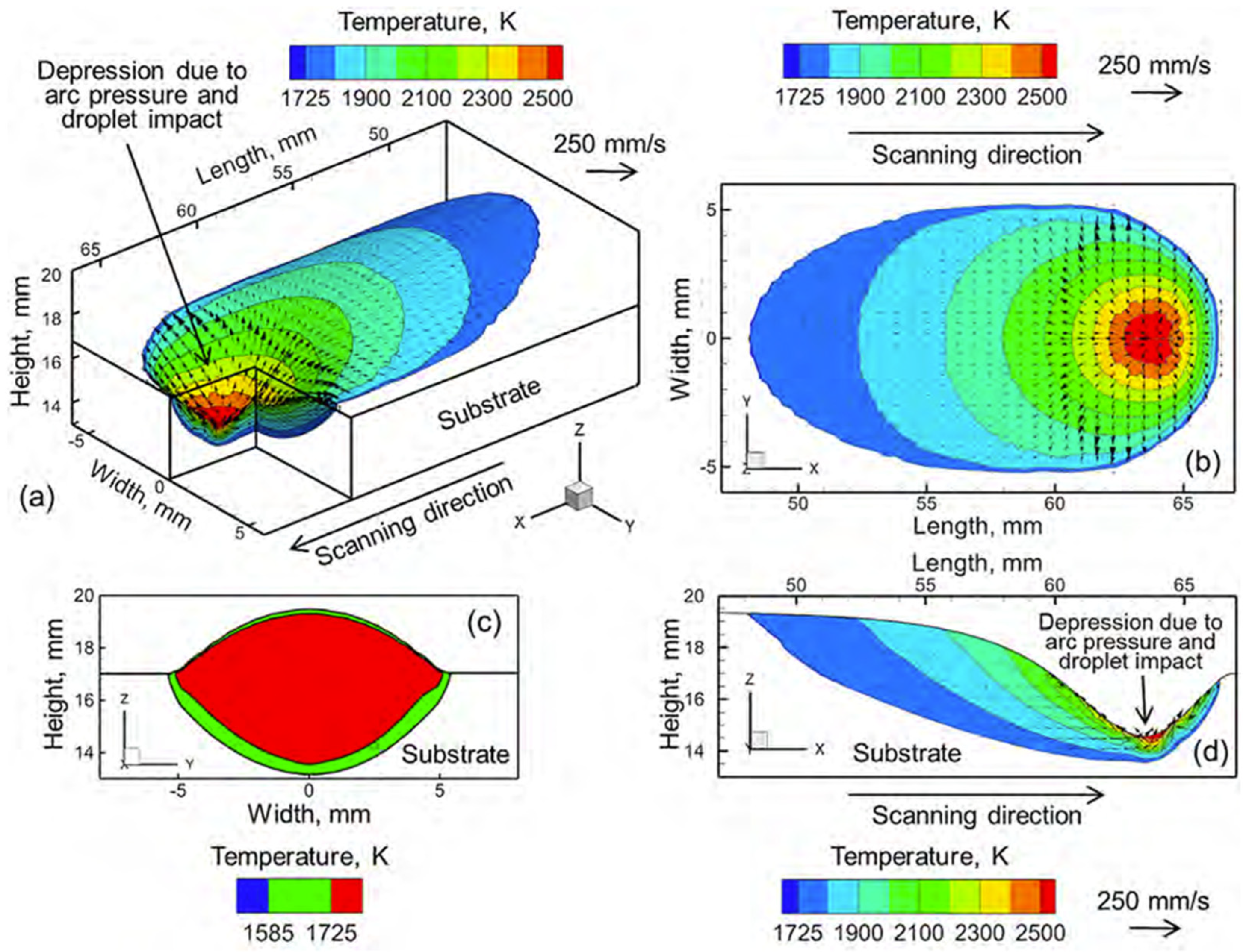
The fluid flow model treats metal in the liquidous state as an incompressible Newtonian fluid, considering buoyancy effects, Marangoni forces, both due to surface tension and temperature gradients, and arc pressure effects that influence the depth and shape of the molten pool shown in
Figure 21. We also considered surface deformation and a pre-calculated deposit shape using free surface energy minimization, which accounts for the arc pressure effects on the melt pool, droplet impact forces, and surface tension effects:
where
represents the source terms such as gravity, surface tension, etc., and
represents the dynamic viscosity. The model dynamically focused computational resources on the molten pool, reducing memory requirements and simulation time by 50%.
This model was then validated against experimental testing of H13 tool steel and Ti-6Al-4V titanium alloy. The setup involved 100 mm long deposits with five hatches, one or two layers deposited on a 250 × 150 × 4 mm AISI 1040 steel substrate. The results showed that convective heat transfer dominated in the WAAM process, which makes it crucial for accurate simulation. Arc pressure was critical for deposition height while increased fluid flow significantly reduces the width. Multi-layer deposition leads to heat accumulation, which requires hatch spacing and interlayer cooling to prevent distortions. Overall, this study improved the heat transfer and fluid flow model for effectively simulating the multi-layer WAAM process.
Zhou et al. [
93] studied a numerical simulation of the heat and mass transient behavior during the layer by layer deposition process in WAAM under an external deflection magnetic field (EDM). Because WAAM is a high deposition rate technology, it suffers from uneven bead morphology and inconsistent cross sections. This leads to poor mechanical properties and surface roughness. In this study, the impact of the EDM on deposition morphology and, specifically, the melt pool dynamics and heat distribution were investigated using a coupled numerical model that integrates the arc physics, melt pool behavior and electromagnetic interactions to predict the heat transfer, melt pool flow behavior, and solidification patterns. For the modeling framework, the standard heat transfer equation is used with the Goldak double ellipsoid model for the arc energy distribution, and the heat loss mechanisms include convective cooling and radiative losses. The EDM, which alters the arc plasma behavior during the deposition process, is governed by the Maxwell equations as
where
is electrical conductivity and
is electric potential. The magnetic force applied to the molten pool (Equation (46)) modifies the molten metal convection and improves the overlapping bead shape and deposition consistency.
In Equation (46),
is current density vector,
is magnetic flux density from the arc,
is externally applied EDM. The melt pool flow is defined as an incompressible Newtonian fluid governed by the Navier–Stokes equation:
where
is dynamic viscosity,
is force due to the thermal expansion, and
is electromagnetic force altering flow patterns. The results showed that the addition of the EDM improved the bead shape of the deposition, created forced convection for better heat and fluid distribution, and reduced temperature gradients, leading to smoother deposition layers. The results confirm that applying an EDM significantly improves bead morphology and overlapping accuracy by modifying arc shape, heat input distribution, and molten pool flow.
Liu et al. [
94] look at how different constitutive models characterize the flow behavior of the molten pool and deposition material in WAAM over a wide range of process parameters such as strain rates and temperatures. WAAM’s complexity of the layer-by-layer build process causes large fluctuations in heat and strains and creates significant microstructural variations compared to traditional subtractive manufacturing methods whose material properties are generally isotropic. Having an accurate model for formation of microstructure formation and mechanical response of the part under thermal deformations is critical. This study implements three constitutive models: a strain-compensated Arrhenius model, modified Johnson–Cook model and a genetic algorithm-optimized backpropagation artificial neural network (GA-BP ANN).
The strain-compensated Arrhenius model is widely used in high-temperature deformation studies since it accounts for the complex flow state of the deposition process by incorporating temperature-dependent flow stress predictions. This flow stress is predicted using the strain rate given in Equation (48), with the material parameters determined by linear regression techniques.
where
, α, and n are material constants,
is the activation energy for deformation,
is the universal gas constant, and
is the absolute temperature.
While this model produces accurate predictions, it is computationally expensive. The next model considered is the Modified Johnson–Cook model, which is commonly used in high strain rate deformation modeling. The classic model assumes that flow stress depends on strain, strain rate, and temperature. To improve accuracy, the classical model was modified to account for strain rate-dependent hardening and coupled thermal-softening effects. The modified version also includes Voce’s law to better capture the deformation process at high temperatures and large strain deformations [
95]. The resulting equation is given as
where
,
, and
are parameters governing the shape of the stress–strain curve,
is the strain rate sensitivity coefficient, and
and
are thermal softening parameters. While the modified Johnson–Cook model improved prediction accuracy, it struggled to correctly model extreme deformation conditions in WAAM. To overcome this, a genetic algorithm-optimized backpropagation artificial neural network (GA-BP ANN) was implemented to handle dynamic and nonlinear process in WAAM. This machine-learning-based model, using an artificial neural network (ANN), includes the input later for strain, strain rate, and temperature. The hidden layer consists of the neurons responsible for the decision-making process and the output that predicts the flow stress.
This model allows for a nonlinear fitting capability, which can capture the complex flow stress behavior without requiring a predefined equation form, and high adaptability when working with various temperature–strain rate conditions present in WAAM. It lacks, however, physical interpretability, requires large data sets to train, and is computationally expensive. Overall, the GA-BP ANN model outperforms traditional models but lacks physical interpretability, while the Arrhenius and modified Johnson–Cook models provide solid alternatives for their mechanical grounding.
4.4. Powder Bed Behavior in PBF
Defects such as pores, inter-layer delamination, and thermal deformation are major concerns in Powder Bed Fusion (PBF) due to the localized melting and rapid solidification of metal powders during the process [
24]. These defects can compromise mechanical properties, density, and overall part reliability. Additionally, the presence of unfused or partially fused powder particles can contribute to lack of fusion porosity, further reducing part integrity [
96]. To address these challenges, macroscale modeling approaches, such as finite element methods (FEM), are widely used to simulate the PBF process [
54]. These simulations help predict temperature distribution, melt pool dynamics, stress evolution, and defect formation during the layer-by-layer deposition process. Accurate modeling of these characteristics is essential for process optimization, enabling engineers to adjust parameters such as laser power, scan speed, and layer thickness to improve part quality and reduce defects.
Many parameters affect the performance of AM processes. Studying their relationship and the repercussions between them is important to analyze, improve, and generate good results in this technology [
92]. These processes often do not have feedback control processes to predict and control the quality outcome, working in an open loop. In the PBF, parameters such as laser, environment, moisture, density, or any condition of the powder significantly influence the process. A recent study [
97] developed an ‘in situ’ method to determine the powder bed density in a PBF process, which has a great influence on the mechanical behavior of the powder. Smooth, clean, and dry particles are important for achieving a high powder layer density (PLD).
It is necessary to verify operational requirements and flow characteristics of the powder to achieve high quality products. Process parameters such as shape, speed, and environmental parameters like humidity and temperature can affect the spreadability of powder in PBF processes [
79]. The preheating stage in PBF provides a better quality in manufactured materials because it reduces thermal stress, which decreases the formation of cracks, residual stresses, and deformations. Preheating the powder before starting the PBF process could affect the flowability and spreadability of the powder; therefore, it is essential to evaluate the impact of temperature on the powder bed. Ref. [
79] uses FEM to simulate the behavior of the powder.
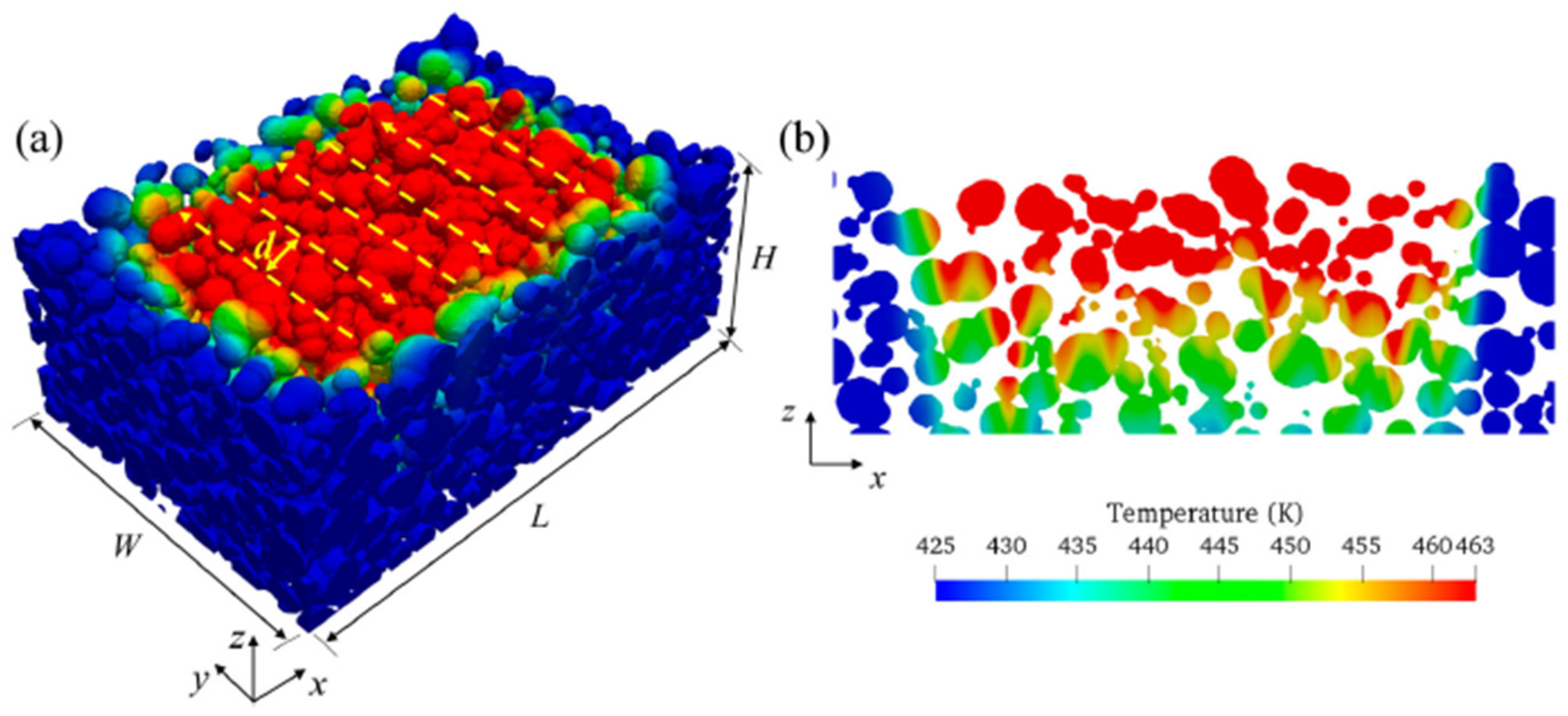
Tan et al. [
98] use a Multiphysics approach to simulate the recoating, melting, and coalescence processes of polymer powder. The discrete element method (DEM) is used to simulate the powder recoating, and a computational fluid dynamic (CFD) is employed to predict the powder melting and joining process. Laser reflection, absorption, and transmission in the powder bed process are considered for the CFD model. The formation of pores due to a lack of fusion and air traps was investigated. DEM models granular materials like powders by considering them as discrete entities with interactions governed by position, orientation, velocity, friction, and other physical parameters. The CFD model considers the reflection, absorption, and transmission of infrared radiation in the powder bed. Surface tension, heat transfer (conduction and convection), viscosity, and heat loss are also considered.
Figure 22 depicts important parameters considered in the CFD analysis.
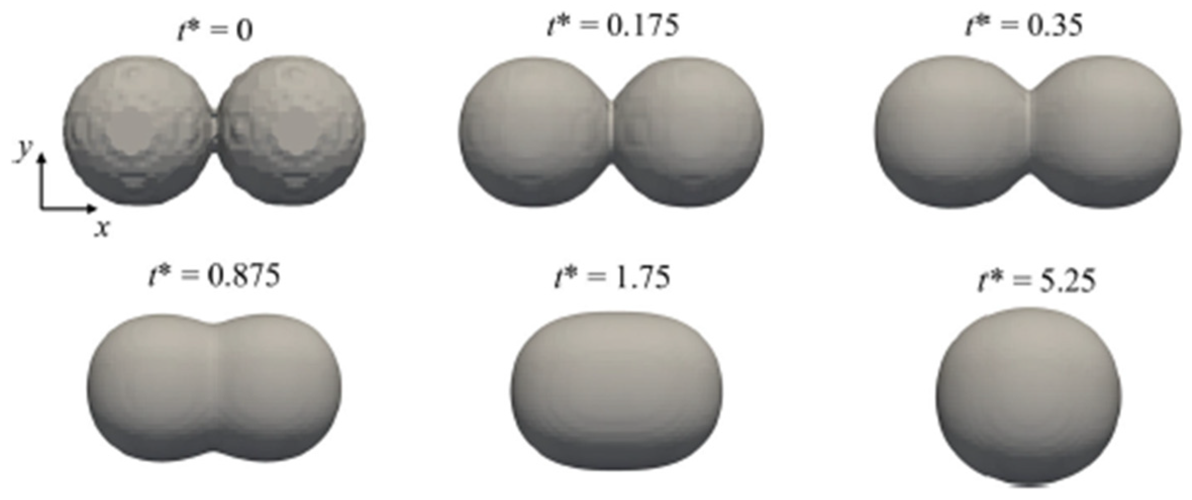
The driving force of two identical spherical particles is the surface tension of the polymer melt, which reduces the surface energy by decreasing the surface-to-volume ratio.
Figure 23 shows two particles initially in contact and the junction formed between them. The dimensionless time t* is defined as shown in Equation (50):
where
represents the surface tension,
represents time,
is the initial particle radius, and
is the dynamic viscosity.
In the simulation, a uniform mesh of 3 µm was used. The first layer printing process was performed on a powder bed twenty times thicker than a normal layer. A thickness of 350 µm was adopted to reduce the dimension of the computational domain.
Figure 24 and
Figure 25 show the predicted melting depths from simulation and the x-z cross sections of one-layer parts obtained from an optical microscope, respectively.
The results revealed that lower viscosity improves densification in printed parts, but excessively small powder particles have a negative effect on the packing quality of the power bed and increase the porosity of power particles [
98]. PBF utilizes a laser to selectively fuse metal powder. Heat transfer and thermal gradients have an important influence on microstructural features, and the quick melting and solidification of the powder can compromise the mechanical characteristics of the parts [
77].
6. Conclusions
This review has explored the various finite element analysis (FEA) and computational modeling techniques used to simulate Direct Energy Deposition (DED), Wire Arc Additive Manufacturing (WAAM), and Powder Bed Fusion (PBF). Each of these metal additive manufacturing (AM) methods presents unique challenges in terms of thermal modeling, mechanical deformation, residual stress formation, and material flow dynamics.
Table 1 summarizes and describes the individual problems studied by each paper reviewed along with their respective authors.
The literature reviewed demonstrated significant advancements in numerical simulations, particularly in developing high-fidelity models that integrate multi-physics phenomena to predict melt pool behavior, microstructure evolution, and process-induced defects which were then compared against experimental validation. However, due to the wide variation in validation techniques such as sample sizes, substantial assumptions of physics, and extensive simplification of the build geometries, the overall strength and viability of these validations remains difficult to quantify.
For DED, studies have focused on improving heat source models, material deposition accuracy, and residual stress predictions, with advancements in adaptive meshing and transient thermal analysis improving computational efficiency. WAAM, with its high deposition rates, has driven research in steady-state thermal analysis, thermomechanical coupling, and stress relaxation phenomena, optimizing build parameters and reducing distortion. Finally, PBF modeling has progressed towards more detailed mesoscale and microscale simulations, capturing the complex melt pool dynamics, heat transfer mechanisms, and powder–bed interactions that affect final part quality.
A key takeaway across all three AM techniques is the growing trend towards multi-scale, multi-physics, and machine learning-enhanced models. While finite element models (FEM), computational fluid dynamics (CFD), and discrete element methods (DEM) have provided powerful tools for understanding process physics, emerging data-driven approaches, reduced-order models, and real-time simulations are proving crucial for process optimization and defect mitigation.
While this review has primarily focused on physics-based simulation strategies, we acknowledge the increasing relevance of machine learning (ML) methods in AM modeling, particularly for surrogate modeling, process monitoring, and uncertainty quantification. Given the rapid growth and scope of ML applications in this space, we suggest that a dedicated review would be valuable to comprehensively address recent ML-driven advancements in metal AM simulation.


