Article

Controlled Hydrogen Loading of Magnesium Thin Films in KOH—Effects on the Hydride Nucleation and Growth Regimes

1
Institute for Applied Materials (IAM-WK), Karlsruhe Institute of Technology (KIT), Engelbert-Arnold-Straße 4, 76131 Karlsruhe, Germany
2
Fraunhofer Institute for Solar Energy Systems, Dep. Electrical Energy Storage, Heidenhofstr. 2, 79110 Freiburg, Germany
3
Freiburg Materials Research Center (FMF), Stefan-Meier-Straße 21, 79104 Freiburg, Germany
4
Institute for Applied Materials (IAM-ESS), Karlsruhe Institute of Technology (KIT), Hermann-von-Helmholtz-Platz 1, 76344 Eggenstein-Leopoldshafen, Germany
5
Albert Ludwig University Freiburg, Department of Sustainable Systems Engineering (INATECH), Emmy-Noether-Straße 2, 79110 Freiburg, Germany
6
Department of Physics and Astronomy, University of Bologna, Viale Berti Pichat 6/2, 40127 Bologna, Italy
*
Author to whom correspondence should be addressed.
Micro 2024, 4(4), 765-777; https://doi.org/10.3390/micro4040047
Submission received: 31 October 2024 / Revised: 29 November 2024 / Accepted: 3 December 2024 / Published: 5 December 2024
(This article belongs to the Special Issue Advances in Micro- and Nanomaterials: Synthesis and Applications)

Abstract

:
In this work, we propose a strategy to optimize electrochemical hydrogen loading in magnesium–palladium thin films, using 5 M KOH as an electrolyte. Mg thin films of thickness 26 nm were deposited on sapphire (0001) substrates and capped by a 32 nm Pd layer. By performing cyclic voltammetry with in situ optical microscopy, it appears that a loading potential of at least −1.2 V vs. Hg/HgO has to be achieved at the sample’s surface to trigger magnesium hydride formation. Loading potential effects are then further explored by hydrogenography, where different hydride formation mechanisms appear based on the actual potential. With a larger loading potential of −1.6 V vs. Hg/HgO, a magnesium hydride blocking layer is formed; in this case, Pd hydride temporarily forms in the capping layer as hydrogen diffuses towards the magnesium layer. Loading is optimized for a lower potential of −1.2 V vs. Hg/HgO, which leads to larger hydride precipitates and delays the blocking layer formation; in this case, Pd hydride only appears after the magnesium layer is completely hydrided.

1. Introduction

Magnesium is considered a superior option for solid-state hydrogen storage due to the high achievable gravimetric density of 7.6 wt.% upon magnesium hydride (MgH2) formation [1] and because it is an inexpensive and easily available material. Despite these advantages, magnesium possesses significant drawbacks, especially the low diffusivity of hydrogen within the hydride phase [1,2]. This limitation can be partially overcome by employing nanostructured materials. Alongside the mechanical treatment of magnesium as bulk solid and powder [3,4], nanostructured materials can be achieved through thin film technologies, providing improved H kinetics [5], regarding both hydrogen diffusivity and hydride formation. Hence, controlled hydrogen loading in magnesium thin films has been successfully used to study hydrogen’s vertical [6,7,8] and lateral [9] diffusion, to investigate the system’s optical properties [10] and to study hydride formation and growth mechanisms [11,12,13,14,15,16], also in relation to the film’s thickness [17,18].
The Mg-H-phase diagram presents two main stable phases: the α phase corresponding to the solid solution of hydrogen in hcp magnesium, and the hydride-phase MgH2 with a rutile crystal structure; other crystal structures for MgH2 can be observed at high pressures [19]. The solubility of hydrogen in α -Mg depends on temperature and pressure, but it is generally very low. The highest values are around 0.02 H/Mg and were observed at temperatures close to the Mg melting point [20]. Extrapolating from experimental values measured at 400–600 °C, at room temperature, we can expect a value of ~10−7 H/Mg [21,22]. However, experimental values may be higher due to the increased solubility at grain boundaries and other lattice defects. Above this very low solubility limit, the rutile hydride-phase MgH2 forms in equilibrium with the α -Mg solid solution. The stability of the hydride phase depends on the temperature and the hydrogen pressure according to the van ‘t Hoff equation [19]:
ln p e q p 0 = Δ H R T Δ S R
where p e q is the pressure for hydride decomposition, T is the temperature, R is the gas constant, Δ H is the enthalpy of formation and Δ S is the entropy of formation. Several values have been calculated for these quantities [20], generally close to Δ H = −74.5 kJ/mol and Δ S = −135 J/mol/K [21].
According to the literature, hydrogen is often introduced in magnesium samples from the gas phase by gradually increasing the gas pressure in a vacuum chamber. Given the small volume of the film compared to the volume of hydrogen introduced in the chamber, this method does not allow us to directly determine the hydrogen concentration in the sample by gravimetry or volumetry [23]. Thus, the hydrogen concentration is usually indirectly estimated, measuring the sample’s optical transmittance by applying the hydrogenography approach or measuring the resistance variation upon hydride formation [24,25]. Additionally, gas loading presents another limitation: by controlling the applied hydrogen pressure, one measures the chemical potential that is required to trigger the onset of hydride formation, but not necessarily the actual chemical potential during hydride growth for a fixed equilibrium hydrogen concentration in the sample. This can be misleading when there are potential barriers to the nucleation of the hydride, which require a higher driving force to initiate hydride formation. Consequently, with gas loading, it might not be possible to measure intermediate steps in the hydride formation, because once the nucleation barrier is surpassed, the whole sample will transform into the hydride phase before reaching an equilibrium condition due to the high availability of hydrogen in the gas atmosphere. Since one increases the applied hydrogen pressure at each loading step, the isotherms will always be inherently but artificially oriented upwards in the plateau region, even if one manages to measure several steps inside the pressure plateau. This is particularly problematic when the effects of hydrogen-induced stress and stress relaxation in thin films are considered, that result in a reduction in the chemical potential at a given hydrogen concentration [26].
Alternatively, electrochemical reactions can be conducted to introduce hydrogen atoms into metal thin films with defined amounts, allowing for a direct determination of the absorbed hydrogen concentration and an independent determination of the chemical potential at equilibrium [23]. Electrochemical loading of magnesium thin films is, however, challenging. Even if a protective Pd capping layer is added, the films tend to be corroded in standard acidic electrolytes such as Glycerin and Phosphoric acid [12]. Therefore, a different electrolyte has to be used: one alternative is 5 M or 6M KOH. While this electrolyte has been used in the past [9,13,27,28], its advantages and limitations are not yet studied. Recent studies on electrochemical hydrogenation relate to Mg-containing alloys for hydrogen storage and battery materials [29,30,31,32,33,34,35,36,37,38,39,40,41,42]. In these studies, the electrodes are not thin films but compressed powders, and the main focus is on the effect of different compositions of the alloying elements and different catalytic materials on hydrogen storage and kinetics.
This work explores the electrochemical boundary conditions and proposes routes to optimize the hydrogen loading in magnesium thin films in a 5 M KOH electrolyte. The main focus is to understand how controlled hydrogen loading can be achieved and to explore the advantages and disadvantages of the method, also in comparison with the more established gas-phase hydrogen loading method. With this purpose, cyclic voltammetry was combined with in situ optical microscopy and hydrogenography experiments on Mg-Pd thin films. The impact of different loading conditions on hydride nucleation and growth is addressed.

2. Materials and Methods

2.1. Sample Preparation

Magnesium thin films with a thickness of 26 nm were deposited on 1 cm2 sapphire (0001) substrates by cathode argon–ion-beam sputtering. The magnesium layers were always covered with a palladium layer of 32 nm thickness, to prevent oxidation and to enhance hydrogen absorption. As previously introduced, the film thickness was chosen to benefit from faster hydrogenation kinetics and to allow the complete hydrogenation of the sample in a reasonable time frame. The layer thickness was calculated from the deposition time, by knowing the sputter rate for the different target materials. The sputter rate was quantified by depositing reference samples and measuring their thickness by X-ray reflectometry (XRR). The films are uniformly thick, given the small area of the substrate compared to the sputter cone. TEM investigations on Mg-Pd thin films deposited in similar conditions revealed a columnar grain microstructure with fiber texture [11]. The deposition system worked in ultra-high vacuum conditions, with a background pressure of 1 10 10   m b a r . The argon pressure during sputtering was 1.3 10 4   m b a r , and the argon gas had a purity of 99.9999%. A low background pressure is necessary to avoid oxidation of the Mg layer during deposition; for the same reason, the magnesium and palladium targets could be alternated during the deposition without breaking the vacuum conditions. In addition, the magnesium target was eroded for 3 h before depositing the samples to remove the oxide layer that can form over time even in an ultra-high vacuum.

2.2. Hydrogenography

Hydrogen was loaded in the samples via electrochemical reactions in 5 M KOH, using an electrochemical cell in the three-electrode geometry, as shown in Figure 1a. Before loading, the electrolyte was bubbled with argon gas (purity 99.9999%) for 30 min to reduce its O2 content. The sample acted as the working electrode (WE) and it was in direct contact with the electrolyte only through the Pd surface, exposing a circular area of 50   m m 2 . A platinum counter electrode (CE) of area 1   c m 2 was connected to a voltage generator (Keithley 2601 SYSTEM Source Meter, Cleveland, OH, USA) to control the voltage at the sample’s surface. The voltage source was used in combination with a digital timer (company WEG, Jaraguá do Sul, Brazil) to create voltage steps in the electrolyte; during each loading step, H was adsorbed at the sample’s surface, which acts as a cathode. In subsequent steps, hydrogen diffused inside the sample to create a Mg-H solid solution and MgH2. The potential at the sample’s surface was read and recorded against a Sensortechnik Meinsberg Hg/HgO reference electrode (RE) connected to a DAQ board (IOtech PersonalDaq/56, Spectrum Instrumentation, Grosshansdorf, Germany).
The potential at the sample’s surface is especially relevant because—once the equilibrium hydrogen distribution at a given H concentration is reached in the sample—it coincides with Nernst potential. The measured equilibrium potential E e q can, therefore, be converted into an equivalent hydrogen equilibrium pressure (the one that appears in Equation (1)), according to [27,43]:
E e q H g / H g O = R T n F ln p e q p 0 0.0592 p H E 0 H g / H g O = R T n F ln p e q p 0 0.954
where n is the number of electrons involved in the hydrogen evolution reaction. In the rightmost equality we have used the present experimental data, i.e., p H = 14.70 and E 0 H g / H g O = 0.085   V . According to this equation, we can expect an equilibrium potential of −0.78 V for magnesium hydride decomposition and of −0.89 V for palladium hydride decomposition.
The optical part of the setup, necessary for hydrogenography, is shown in Figure 1b. An optical Leica DM 2700 M microscope in transmission mode measured the optical transmittance T of the sample, whose logarithm is proportional to the hydrogen concentration inside the sample according to Lambert–Beer’s law [25,44]:
Δ   c H = 1 ϵ d   l o g T T M
where d is the film’s thickness, ϵ is the extinction coefficient and the transmittance T after each loading step is compared to the initial value T M of the metal. The microscope is equipped with a white light source for transmittance measurement (LED LH113). Images of the films were acquired before each loading step and the recorded transmittance was compared to the initial value. Combining this information with the equilibrium potential reached after each loading step, which is proportional to the hydrogen chemical potential, the formation of magnesium hydride and its lateral distribution in the films can be observed by constructing isotherms. According to Equation (3), the optical transmittance change is mainly related to the formation of the hydride phase in magnesium. Because of the very low solubility of hydrogen in magnesium, the optical effect of the solid solution phase can be disregarded. With respect to the layered arrangement of the sample, hydride formation in the palladium layer also affects the optical transmittance. Both palladium and magnesium become more transparent to visible light with increasing hydrogen content [45], and, thus, their optical transmission images become brighter.
A batch of samples was studied by hydrogenography, changing the loading potential between −1.2 V and −1.6 V.

2.3. Cyclic Voltammetry

Cyclic voltammetry measurements with in situ optical microscopy were performed on the Mg-Pd films using a Gamry Interface 1010B potentiostat and the same electrochemical cell and optical setup employed for hydrogenography (see Figure 1). The potential was scanned at 20 mV/s between 0 and −1.5 V. The starting point was set at −0.2 V, corresponding to the open-circuit potential of the cell.
Using this technique, one can identify oxidation (reduction) electrochemical reactions that occur at the sample’s surface on increasing (decreasing) applied potential, giving rise to anodic (cathodic) current peaks.

3. Results

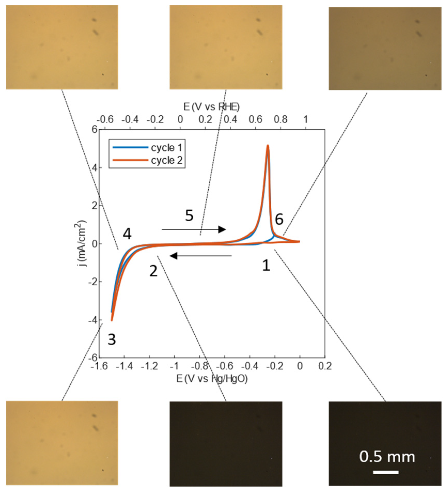
3.1. Cyclic Voltammetry Combined with In Situ Optical Microscopy

To optimize the electrochemical hydrogen loading of Pd-Mg thin films in 5 M KOH, we first needed to understand which electrochemical reactions take place at the sample’s surface and how they are related to the applied driving potential.
Figure 2 reports the CV results for an exemplary 32 nm Pd/26 nm Mg thin film along with optical images of the film. In total, two loading–unloading cycles were performed, and no exfoliation or detachment of the film was observed. The two voltammetry cycles in Figure 2 overlap. A cathodic current peak is observed for potentials below −1.2 V vs. Hg/HgO: this indicates a reduction reaction at the sample surface. This reaction is identified with P d + x H 2 O + x e x O H + P d H x , leading to water splitting and hydrogen absorption in the uppermost Pd layer [13,28]. Part of this hydrogen then diffuses inside the sample to create Mg hydride, as is confirmed by the recorded optical images becoming brighter (panels 2 3 of Figure 2, as opposed to the constant transmittance in panels 1 2). A brighter image is associated with a more transparent sample, which is an expected consequence of the metal-to-insulator transition related to Mg hydride formation. While scanning from −1.5 V to 0 V, the hydride is at first stable, as we can deduce from the constant optical transmittance in Figure 2, panels 4 5. A peak of anodic current appears between −0.4 and −0.2 V vs. Hg/HgO, indicating an oxidation reaction at the sample surface. This reaction is identified with water formation at the sample surface, according to y O H + P d H x P d H x y + y H 2 O + y e [13]. This reaction leads to H desorption from the sample surface, which is accompanied by the decomposition of part of the Mg hydride, as is confirmed by the decreasing optical transmittance in Figure 2, panels 5 6. It is worth noticing that in these conditions, KOH is not directly employed in the reactions for hydrogen production, which only involve splitting and the formation of water molecules. Excluding the changes described above, which are related to hydride formation and decomposition, the measured optical transmittance was constant within the forward and backward scan of both voltammetry cycles. After the first dehydrogenation, the transmittance did not return to the value for metallic magnesium because a fraction of the magnesium hydride was not decomposed in the short time scale of the experiment.
With a relatively fast scan rate of 20 mV/s, we have to apply an overpotential of at least −1.2 V vs. Hg/HgO to trigger hydrogen absorption and, consequently, hydride formation. A similar (or higher) overpotential was applied in hydrogenography experiments to achieve fast hydrogen absorption during short loading pulses of 5 s.

3.2. Potential Curves and Hydride Formation

Figure 3 shows the behavior of the potential measured against Hg/HgO during and after two different loading pulses, together with the film’s transmission images. Different loading conditions were tested, changing the applied potential between −1.2 V and −1.6 V. Here, representative results are reported, corresponding to the lowest and the highest applied potentials. The smallest value of −1.2 V was chosen based on the cyclic voltammetry results. The largest value of −1.6 V was chosen to minimize the formation of hydrogen bubbles at the sample’s surface. In fact, when a too-large potential is applied, not all the produced hydrogen can be absorbed by the sample, and part of it recombines, forming H2 molecules and, consequently, hydrogen bubbles at the sample’s surface.
While the applied potential is different, the pulse duration in both cases is 5 s. The highlighted peaks in Figure 3 correspond to the time interval in which the external potential is applied directly between the sample and the counter electrode. Therefore, the measured potential, in this case, includes an overpotential that drives hydrogen absorption according to the reaction introduced in Section 3.1. After the voltage source is switched off, the potential (sometimes also referred to as electromotive force or EMF [46,47,48]) decreases with a different shape depending on the achieved loading potential. Figure 3a shows that a smaller loading potential of −1.2 V vs. Hg/HgO causes an exponential relaxation curve, while a larger loading potential of −1.6 V vs. Hg/HgO is related to a curve with two plateaus (Figure 3b). As will be shown in the following paragraph, these different shapes of the potential curves and different appearances of the film’s surface can be related to different hydride formation mechanisms.
Hydrogen absorption in the film is revealed by its optical transmission images becoming brighter after each loading step, as shown in Figure 3c,d. A brighter picture indicates that the film’s optical transmittance increases, as is expected as a consequence of MgH2 formation (see Equation (3)). Figure 4 shows an example of a recorded equilibrium potential (EMF)–optical transmittance isotherm for 32 nm Pd/26 nm Mg films, which was constructed using 5 s loading steps at −1.2 V vs. Hg/HgO and at −1.6 V vs. Hg/HgO. We observe two potential plateaus in the curves: the first one is related to the formation of MgH2 and the second one is related to the formation of PdHx. As the loading curves are not expected to become completely flat for this type of sample, the equilibrium potential is approximated by taking the potential value after 10 min from the loading pulse. This results in apparently higher potential values for the sample loaded with −1.6 V pulses, because of the longer time necessary to achieve an equilibrium condition. To exclude electrolyte-related effects on the optical transmittance, caused, for example, by the interaction between the thin films and the K+ cations at the cathode, the results for electrochemical loading were compared to those of gas-phase loading at 1 mbar H2 pressure. Both methods reveal a similar change in optical transmittance upon hydride formation, suggesting that possible optical effects related to the chosen electrolyte are minor compared to the transmittance changes caused by Mg and Pd hydride formation.
At first glance, this isotherm provides similar information to the pressure–transmission isotherms that are usually measured by the gas-phase loading of hydrogen in magnesium–palladium thin films. However, as stated in the introduction and detailed in the following paragraph, the potential curves recorded during each loading step convey more information than just the final plateau potential used to construct isotherms.
The measured potentials of −0.31 V and −0.35 V for magnesium hydride formation and −0.45 V for palladium hydride formation differ significantly from the ones calculated from Equation (2), respectively −0.78 V and −0.89 V. Even though the distance between the magnesium and palladium hydride plateaus is consistent with previous results [27], the measured equilibrium potentials are shifted upward by 0.45 V with respect to the expected values. This shift can be explained by oxygen gas dissolved in the electrolyte. In the presence of oxygen, the reactions previously introduced for hydrogen loading and unloading (see Section 3.1) are accompanied by a second redox system, namely O 2 + 2 H 2 O + 4 e 4 O H [49], whose equilibrium potential is +0.28 V vs. Hg/HgO in 5 M KOH. As a consequence, under open-circuit conditions, the measured potential is shifted upward with respect to the genuine equilibrium potential of the metal–hydrogen system [49]. Hence, this effect needs to be addressed and possibly avoided. To reduce the oxygen content, the electrolyte is usually bubbled with argon gas before and during hydrogen loading [49].
In this work, the electrolyte was only bubbled before the experiment because of the peculiar geometry of the hydrogenography cell. In fact, to combine electrochemical and optical measurements, the sample has to lie flat on top of the cell so that it can be observed with the optical microscope. Therefore, if the electrolyte were bubbled during hydrogen loading, argon bubbles would collect at the sample’s surface and interfere with the experiment. It is also important to notice that the potential shift caused by oxygen gas is maximum in open-circuit conditions, and it was reported to vanish when an oxidation or reduction current is present at the working electrode [49], as was the case during the loading steps and the cyclic voltammetry experiments. Regarding cyclic voltammetry, the shorter duration of the experiments, which were performed immediately after the bubbling of the electrolyte, also minimizes oxygen effects.

3.3. Dependence of the Potential Curves on the Loading Potential

The previous paragraph showed that the potential curves during Mg hydride formation exhibit different shapes based on the potential applied during the loading step (Figure 3). These effects are independent of the observed EMF shifts due to oxygen in the electrolyte. The different behaviors are accompanied by different optical appearances of the films during Mg hydride formation. Indeed, when a potential of −1.6 V vs. Hg/HgO is achieved during the loading step, the measured curve exhibits two plateaus during the relaxation to equilibrium (Figure 3b). The first plateau is observed around −0.45 V, the potential associated with Pd hydride formation in the presence of oxygen in the electrolyte. This loading potential is also linked to a spatially homogeneous variation in the brightness of the recorded images, indicating that the hydride precipitates are smaller than the microscope’s resolution limit of 2.11   μ m (Figure 3d). With a smaller potential of −1.2 V vs. Hg/HgO during the loading step, the measured potential relaxed directly to the final equilibrium value of −0.32 V (Figure 3a), corresponding to MgH2 formation. With this lower potential, some of the hydride precipitates were large enough to be observed with the optical microscope (Figure 3c).
We pointed out that the first plateau in Figure 3b is centered at the same potential of −0.45 V vs. Hg/HgO observed during Pd hydride formation (see Figure 4). Hence, it might be linked to H residing in the Pd layer during the process of equilibration of the H distribution in the sample and to intermediate Pd hydride formation. More details about hydride formation mechanisms and their relation to the applied loading potential will be introduced in the Discussion Section.

4. Discussion

Figure 3 shows how different loading potentials are related to different shapes of the EMF curves and different appearances of the film during hydride formation. A schematic representation of the proposed hydride formation mechanism for the two different loading potentials is shown in Figure 5.
For the larger loading potential of −1.6 V vs. Hg/HgO (Figure 5a), a first temporary plateau appears around −0.45 V, the potential value associated with the palladium hydride formation in our loading cell. This indicates that palladium hydride is briefly formed in the Pd capping layer, which is directly in contact with the electrolyte, before H atoms can diffuse into the Mg layer to create MgH2. As MgH2 is thermodynamically more stable than the Pd hydride, and as the amount of H atoms is limited, the Pd hydride has to decompose for MgH2 to form.
The stability of the temporarily formed Pd hydride can also be enhanced by the presence of a MgH2 blocking layer [11,12,50] at the interface between magnesium and palladium, hindering the diffusion of H atoms into the Mg layer. Hence, the formation of Pd hydride and the MgH2 blocking layer are coupled processes triggered by the large driving force of H supplied to the sample.
In thin films, MgH2 usually nucleates starting from the Mg-Pd interface [11,12,50]. The blocking effect occurs once MgH2 completely covers the interface, because hydrogen diffusion is much slower in this phase compared to α -Mg. In fact, the H diffusivity in MgH2 was reported to be D H M g H 2 = 1.1 10 20   m 2   s 1 at 305 K [51], while for the α phase, we expect values around 10 10 10 11   m 2 s 1 at room temperature [52,53,54].
As shown in previous works [12], the formation of a blocking layer depends on the driving force for hydride nucleation, which is proportional to the introduced H concentration step and, therefore, to the applied loading potential. In fact, the hydride nucleation site density depends on the driving force for nucleation, as illustrated in Figure 3. For the high potential of −1.6 V vs. Hg/HgO, the hydride nucleation site density is very high, thereby leading to coalescence of hydride nuclei and blocking layer formation. In this case, individual hydride domains cannot be distinguished in the optical transmission image (Figure 3d), and a homogeneous increase in transparency is observed. However, the blocking layer can be observed in Figure 3d because of the (final) lighter optical transmission image, and by the presence of the transient Pd hydride in the EMF curve. On the other hand, for a smaller driving force of −1.2 V vs. Hg/HgO, a low number density of hydride nuclei forms; these nuclei grow to larger half-spherical particles, separated by the remaining α-Mg-H phase. In this case, the formation of the blocking layer is delayed as it will take longer for the low-number-density hydride nuclei to finally coalesce and form a continuous layer, as represented in Figure 5b. In the meantime, H can still diffuse through the α -Mg regions in between the hydride precipitates, resulting in a higher global diffusivity. This behavior is confirmed by the optical images showing large bright dots for the lower loading potential (Figure 3c). According to Lambert–Beer’s law (Equation (3)), this is due to a higher local H concentration and, because of the strong contrast, to MgH2 precipitates. The mean MgH2 precipitate diameter follows a lognormal distribution with an average value of 5.98 ± 0.04   μ m . In line with this interpretation, the EMF curve no longer exhibits a Pd hydride plateau at −0.45 V for the lower loading voltage, since the hydrogen directly diffuses into the Mg layer.
Thus, the loading potential difference of ΔE = 0.4 V has drastic influences on the hydride precipitate distribution and the blocking layer formation in the Mg film, as they switch the MgH2 growth mode from growth-controlled to nucleation-controlled.
After these considerations, the advantages of electrochemical loading in KOH, e.g., compared to gas-phase loading, become apparent. The first advantage is the possibility of measuring the potential at the sample’s surface in the time window that goes from the loading voltage pulse to the final equilibrium EMF for a fixed H concentration: in this sequence, the recorded EMF curves convey information on the actual thermodynamic path the system treads during hydride formation. Secondly, this path can be influenced by tuning the potential applied during the loading steps. In fact, it is shown that magnesium hydride formation can be optimized by reducing the applied voltage, and thus avoiding the formation of a MgH2 blocking layer.
Despite these advantages, electrochemical loading of Mg thin films in 5 M KOH has some limitations. The main one is that not all the hydrogen created at the sample’s surface is eventually absorbed by the sample. Part of this hydrogen will desorb from the surface, creating H2 bubbles, and, therefore, introducing an error in the calculated H concentration. The amount of desorbed H2 depends on the induced concentration step at the sample’s surface; therefore, it can also be influenced by the loading voltage and time. In general, short pulses with a low loading potential will introduce a smaller error in the calculated H concentration. The second disadvantage is the error in the measured potentials introduced by oxygen dissolved in the electrolyte. This effect can be partially solved by electrolyte bubbling before and during hydrogen loading, but as shown above, that might not always be possible for every experimental setup.
In total, combining information from hydrogenography and cyclic voltammetry measurements, we are able to determine the optimal potential for fast electrochemical hydrogen loading in 5 M KOH. The experiments have shown that the optimal loading potential needs to be high enough to start the electrochemical reaction leading to H adsorption on the sample’s surface (see Figure 2). This sets a minimum potential value of about E = −1.2 V, to be achieved between the sample and Hg/HgO reference electrode by applying a proper voltage between the sample and platinum counter electrode. At the same time, the achieved potential needs to be low enough to limit the hydrogen supply to the sample and to delay the formation of a magnesium hydride blocking layer, so that one can benefit from a faster H diffusion regime for the longest time possible. Hence, there is a narrow range of loading potentials around −1.2 V vs. Hg/HgO for optimum loading conditions, in 5 M KOH. This method should be employed in the future to find the optimal loading voltage for different electrolytes.

5. Conclusions

In this study, we propose a way to optimize the electrochemical hydrogen loading of magnesium thin films in a 5 M KOH electrolyte. The first step consists of combining cyclic voltammetry measurements with in situ optical microscopy to identify the minimum potential vs. Hg/HgO that should be applied to introduce hydrogen into the sample. Given this constraint, the optimal potential value can be identified by observing the EMF curves during hydrogen absorption in the subsequent open-circuit condition. In this case, the formation of the hydride phase was optimized by lowering the applied potential and, therefore, avoiding the formation of a Mg hydride blocking layer.
This optimization process is not possible for the gas-phase loading method, as it relies on the main advantages offered by electrochemical loading in KOH, namely the following:
-
The ability to closely follow the time evolution of the chemical potential within each loading step, by measuring the EMF at the thin film sample’s surface. This is impossible to do with gas-phase loading and, as shown in this paper, carries information on the behavior of the system during hydride formation.
-
The ability to influence the behavior of the system within each loading step by acting on the applied loading voltage. It is here demonstrated how magnesium hydride formation can be optimized by choosing the appropriate loading voltage.
This combined method can be used to optimize the loading conditions for hydrogen storage systems based on MgH2. A similar method may also be extended to other electrolytes and to other metals whose optical transmittance changes upon hydride formation, such as yttrium, lanthanum and other rare earth elements [55,56].

Author Contributions

Conceptualization, A.P., L.P. and S.W.; methodology, A.P. and S.W.; formal analysis, G.G.; investigation, G.G.; resources, A.P., S.W., S.D. and A.S.; writing—original draft preparation, G.G.; writing—review and editing, A.P., L.P., S.W. and S.D.; visualization, G.G.; supervision, A.P. and L.P.; funding acquisition, A.P. All authors have read and agreed to the published version of the manuscript.

Funding

This research was funded by the Friedrich und Elisabeth Boysen-Stiftung project number BOY-177.

Data Availability Statement

The original contributions presented in this study are included in the article. Further inquiries can be directed to the corresponding author.

Conflicts of Interest

The authors declare no conflict of interest.

References

  1. Schlapbach, L.; Züttel, A. Hydrogen-Storage Materials for Mobile Applications. Nature 2001, 414, 353–358. [Google Scholar] [CrossRef] [PubMed]
  2. Shao, H.; He, L.; Lin, H.; Li, H.-W. Progress and Trends in Magnesium-Based Materials for Energy-Storage Research: A Review. Energy Technol. 2018, 6, 445–458. [Google Scholar] [CrossRef]
  3. Leiva, D.R.; Jorge, A.M.; Ishikawa, T.T.; Botta, W.J. Hydrogen Storage in Mg and Mg-Based Alloys and Composites Processed by Severe Plastic Deformation. Mater. Trans. 2019, 60, 1561–1570. [Google Scholar] [CrossRef]
  4. Zaluska, A.; Zaluski, L.; Ström–Olsen, J.O. Nanocrystalline Magnesium for Hydrogen Storage. J. Alloys Compd. 1999, 288, 217–225. [Google Scholar] [CrossRef]
  5. Jinzhe, L.; Lider, A.M.; Kudiiarov, V.N. An Overview of Progress in Mg-Based Hydrogen Storage Films*. Chin. Phys. B 2019, 28, 098801. [Google Scholar] [CrossRef]
  6. Karst, J.; Sterl, F.; Linnenbank, H.; Weiss, T.; Hentschel, M.; Giessen, H. Watching in Situ the Hydrogen Diffusion Dynamics in Magnesium on the Nanoscale. Sci. Adv. 2020, 6, eaaz0566. [Google Scholar] [CrossRef]
  7. Hadjixenophontos, E.; Michalek, L.; Weigel, A.; Schmitz, G. Hydrogen Sorption Kinetics in MgH2 and TiH2 Thin Films. Defect Diffus. Forum 2018, 383, 127–132. [Google Scholar] [CrossRef]
  8. Hadjixenophontos, E.; Zhang, K.; Weigel, A.; Stender, P.; Schmitz, G. Hydrogenation of Pd/Mg Films: A Quantitative Assessment of Transport Coefficients. Int. J. Hydrogen Energy 2019, 44, 27862–27875. [Google Scholar] [CrossRef]
  9. Teichmann, N.; Hamm, M.; Pundt, A. Fast Lateral Hydrogen Diffusion in Magnesium-Hydride Films on Sapphire Substrates Studied by Electrochemical Hydrogenography. Int. J. Hydrogen Energy 2018, 43, 1634–1642. [Google Scholar] [CrossRef]
  10. Drechsler, V.; Krauth, J.; Karst, J.; Giessen, H.; Hentschel, M. Switchable Optical Nonlinearity at the Metal to Insulator Transition in Magnesium Thin Films. ACS Photonics 2020, 7, 1560–1568. [Google Scholar] [CrossRef]
  11. Hamm, M.; Bongers, M.D.; Roddatis, V.; Dietrich, S.; Lang, K.-H.; Pundt, A. In Situ Observation of Hydride Nucleation and Selective Growth in Magnesium Thin-Films with Environmental Transmission Electron Microscopy. Int. J. Hydrogen Energy 2019, 44, 32112–32123. [Google Scholar] [CrossRef]
  12. Uchida, H.T.; Wagner, S.; Hamm, M.; Kürschner, J.; Kirchheim, R.; Hjörvarsson, B.; Pundt, A. Absorption Kinetics and Hydride Formation in Magnesium Films: Effect of Driving Force Revisited. Acta Mater. 2015, 85, 279–289. [Google Scholar] [CrossRef]
  13. Xin, G.; Wang, Y.; Fu, H.; Li, G.; Zheng, J.; Li, X. Promising Electrochemical Hydrogen Storage Properties of Thick Mg-Pd Films Obtained by Insertion of Thin Ti Interlayers. Phys. Chem. Chem. Phys. 2014, 16, 3001–3006. [Google Scholar] [CrossRef] [PubMed]
  14. Lyu, J.; Elman, R.R.; Svyatkin, L.A.; Kudiiarov, V.N. Theoretical and Experimental Research of Hydrogen Solid Solution in Mg and Mg-Al System. Materials 2022, 15, 1667. [Google Scholar] [CrossRef]
  15. Pacanowski, S.; Wachowiak, M.; Jabłoński, B.; Szymański, B.; Smardz, L. Interface Mixing and Hydrogen Absorption in Pd/Mg and Pd/Al/Mg Thin Films. Int. J. Hydrogen Energy 2021, 46, 806–813. [Google Scholar] [CrossRef]
  16. Pivak, Y.; Schreuders, H.; Dam, B. Thermodynamic Properties, Hysteresis Behavior and Stress-Strain Analysis of MgH2 Thin Films, Studied over a Wide Temperature Range. Crystals 2012, 2, 710–729. [Google Scholar] [CrossRef]
  17. Mooij, L.P.A.; Baldi, A.; Boelsma, C.; Shen, K.; Wagemaker, M.; Pivak, Y.; Schreuders, H.; Griessen, R.; Dam, B. Interface Energy Controlled Thermodynamics of Nanoscale Metal Hydrides. Adv. Energy Mater. 2011, 1, 754–758. [Google Scholar] [CrossRef]
  18. Mounkachi, O.; Akrouchi, A.; Tiouitchi, G.; Lakhal, M.; Salmani, E.; Benyoussef, A.; Kara, A.; El Kenz, A.; Ez-Zahraouy, H.; El Moutaouakil, A. Stability, Electronic Structure and Thermodynamic Properties of Nanostructured MgH2 Thin Films. Energies 2021, 14, 7737. [Google Scholar] [CrossRef]
  19. Crivello, J.-C.; Dam, B.; Denys, R.V.; Dornheim, M.; Grant, D.M.; Huot, J.; Jensen, T.R.; Jongh, P.; Latroche, M.; Milanese, C.; et al. Review of Magnesium Hydride-Based Materials: Development and Optimisation. Appl. Phys. A 2016, 122, 97. [Google Scholar] [CrossRef]
  20. Zeng, K. Critical Assessment and Thermodynamic Modeling of the Mg–H System. Int. J. Hydrogen Energy 1999, 24, 989–1004. [Google Scholar] [CrossRef]
  21. Stampfer, J.F.; Holley, C.E.; Suttle, J.F. The Magnesium-Hydrogen System 1–3. J. Am. Chem. Soc. 1960, 82, 3504–3508. [Google Scholar] [CrossRef]
  22. San-Martin, A.; Manchester, F.D. The H−Mg (Hydrogen-Magnesium) System. J. Phase Equilibria 1987, 8, 431–437. [Google Scholar] [CrossRef]
  23. Kirchheim, R.; Pundt, A. Hydrogen in Metals. In Physical Metallurgy; Elsevier: Amsterdam, The Netherlands, 2014; pp. 2597–2705. ISBN 978-0-444-53770-6. [Google Scholar]
  24. Borgschulte, A.; Lohstroh, W.; Westerwaal, R.J.; Schreuders, H.; Rector, J.H.; Dam, B.; Griessen, R. Combinatorial Method for the Development of a Catalyst Promoting Hydrogen Uptake. J. Alloys Compd. 2005, 404–406, 699–705. [Google Scholar] [CrossRef]
  25. Gremaud, R.; Broedersz, C.P.; Borsa, D.M.; Borgschulte, A.; Mauron, P.; Schreuders, H.; Rector, J.H.; Dam, B.; Griessen, R. Hydrogenography: An Optical Combinatorial Method to Find New Light-Weight Hydrogen-Storage Materials. Adv. Mater. 2007, 19, 2813–2817. [Google Scholar] [CrossRef]
  26. Wagner, S.; Pundt, A. Quasi-Thermodynamic Model on Hydride Formation in Palladium–Hydrogen Thin Films: Impact of Elastic and Microstructural Constraints. Int. J. Hydrogen Energy 2016, 41, 2727–2738. [Google Scholar] [CrossRef]
  27. Vermeulen, P.; Ledovskikh, A.; Danilov, D.; Notten, P.H.L. Thermodynamics and Kinetics of the Thin Film Magnesium–Hydrogen System. Acta Mater. 2009, 57, 4967–4973. [Google Scholar] [CrossRef]
  28. Vermeulen, P.; van Thiel, E.F.M.J.; Notten, P.H.L. Ternary MgTiX-Alloys: A Promising Route towards Low-Temperature, High-Capacity, Hydrogen-Storage Materials. Chemistry 2007, 13, 9892–9898. [Google Scholar] [CrossRef]
  29. Gao, J.; Shen, Y.; Sun, Y.; Feng, Z.; Shi, P.; Xie, K.; Lin, L.; Guo, X.; Zhang, S. CrSe2 Based Single-Cluster Catalysts with Controllable Charge States for the Oxygen Reduction and Hydrogen Evolution Reactions. J. Colloid Interface Sci. 2025, 678, 1122–1131. [Google Scholar] [CrossRef] [PubMed]
  30. Nivedhitha, K.S.; Umarfarooq, M.A.; Banapurmath, N.R.; Venkatesh, R.; Khan, T.; Shreeshail, M.L. Hydrogen Storage Properties of Magnesium Based Alloys Mg67Ni(32−x)Nb1Alx (x = 1, 3, and 5) by Using Response Surface Methodology. Phys. Scr. 2024, 99, 055013. [Google Scholar] [CrossRef]
  31. Nivedhitha, K.S.; Venkatesh, R.; Banapurmath, N.R.; Ramesh, K.; Sajjan, A.M.; Chikkatti, P.B.S.; Yogesh; Jain, A.; Nithya, C. Exploring the Influence of Single-Walled Carbon Nanotubes Substituted Mg–Ti Alloy for Hydriding and Dehydriding Properties. Int. J. Hydrogen Energy 2024, 59, 272–281. [Google Scholar] [CrossRef]
  32. Nivedhitha, K.S.; Venkatesh, R.; Banapurmath, N.R. Activation Energy Study on Nanostructured Niobium Substituted Mg2Ni Intermetallic Alloy for Hydrogen Storage Application. Phys. Scr. 2022, 98, 015706. [Google Scholar] [CrossRef]
  33. Verbovytskyy, Y.; Vlad, K.; Zavaliy, I.; Rożdżyńska-Kiełbik, B.; Pavlyuk, V. Crystal Structure and Hydrogen Sorption Properties of Nd0.5Y0.5MgNi4−xCox Alloys (x = 0–3). Solid State Sci. 2024, 156, 107674. [Google Scholar] [CrossRef]
  34. Verbovytskyy, Y.; Oprysk, V.; Zavaliy, I.; Vlad, K.; Berezovets, V.; Kosarchyn, Y. The Impact of La/Y and Ni/Co Substitutions on the Gas-Phase and Electrochemical Hydrogenation Properties of the La3−xMgxNi9 Alloys. J. Alloys Compd. 2024, 977, 173247. [Google Scholar] [CrossRef]
  35. Verbovytskyy, Y.V.; Oprysk, V.V.; Shtender, V.V.; Zavaliy, I.Y. Hydrogen Sorption Properties of Materials Based on Alloys and Compounds with High Contents of Magnesium. Mater. Sci. 2021, 57, 366–376. [Google Scholar] [CrossRef]
  36. Verbovytskyy, Y.; Oprysk, V.; Paul-Boncour, V.; Zavaliy, I.; Berezovets, V.; Lyutyy, P.; Kosarchyn, Y. Solid Gas and Electrochemical Hydrogenation of the Selected Alloys (R′,R″)2−xMgxNi4−yCoy (R′, R″ = Pr, Nd; x = 0.8–1.2; y = 0–2). J. Alloys Compd. 2021, 876, 160155. [Google Scholar] [CrossRef]
  37. Jiang, W.; Chen, Y.; Hu, M.; Zeng, C.; Liang, C. Rare Earth-Mg-Ni-Based Alloys with Superlattice Structure for Electrochemical Hydrogen Storage. J. Alloys Compd. 2021, 887, 161381. [Google Scholar] [CrossRef]
  38. Liu, Y.-C.; Qi, Y.; Zhang, W.; Gao, J.-L.; Zhang, Y.-H. Highly Improved Hydrogen Storage Dynamics of Nanocrystalline and Amorphous NdMg12-Type Alloys by Mechanical Milling. J. Iron Steel Res. Int. 2020, 27, 1236–1246. [Google Scholar] [CrossRef]
  39. Liu, J.; Zhu, S.; Cheng, H.; Zheng, Z.; Zhu, Z.; Yan, K.; Han, S. Enhanced Cycling Stability and High Rate Dischargeability of A2B7-Type La–Mg–Ni-Based Alloys by in-Situ Formed (La,Mg)5Ni19 Superlattice Phase. J. Alloys Compd. 2019, 777, 1087–1097. [Google Scholar] [CrossRef]
  40. Muthu, P.; Sinnaeruvadi, K. Facilitation of Quasi-Reversible Effect with Rapid Diffusion Kinetics on Mg0.9−xTi0.1Nix High Energy Ball Milled Powders for Ni-MH Batteries. J. Alloys Compd. 2019, 793, 155–169. [Google Scholar] [CrossRef]
  41. Venkateswari, A.; Nithya, C.; Kumaran, S. Electrochemical Behaviour of Mg67Ni(33−x)Nbx (X = 0, 1, 2 and 4) Alloy Synthesized by High Energy Ball Milling. Procedia Mater. Sci. 2014, 5, 679–687. [Google Scholar] [CrossRef]
  42. Wan, C.; Denys, R.V.; Yartys, V.A. Effect of Yttrium Content in the La2−xYxMgNi9 Battery Anode Alloys on the Structural, Hydrogen Storage and Electrochemical Properties. Dalton Trans. 2022, 51, 12986–12995. [Google Scholar] [CrossRef] [PubMed]
  43. Mütschele, T.; Kirchheim, R. Hydrogen as a Probe for the Average Thickness of a Grain Boundary. Scr. Metall. 1987, 21, 1101–1104. [Google Scholar] [CrossRef]
  44. Borsa, D.M.; Gremaud, R.; Baldi, A.; Schreuders, H.; Rector, J.H.; Kooi, B.; Vermeulen, P.; Notten, P.H.L.; Dam, B.; Griessen, R. Structural, Optical, and Electrical Properties of MgyTi1−yHx Thin Films. Phys. Rev. B 2007, 75, 205408. [Google Scholar] [CrossRef]
  45. Isidorsson, J.; Giebels, I.A.M.E.; Arwin, H.; Griessen, R. Optical Properties of MgH2 Measured in Situ by Ellipsometry and Spectrophotometry. Phys. Rev. B 2003, 68, 115112. [Google Scholar] [CrossRef]
  46. Kirchheim, R.; McLellan, R.B. Electrochemical Methods for Measuring Diffusivities of Hydrogen in Palladium and Palladium Alloys. J. Electrochem. Soc. 1980, 127, 2419–2425. [Google Scholar] [CrossRef]
  47. Mütschele, T.; Kirchheim, R. Segregation and Diffusion of Hydrogen in Grain Boundaries of Palladium. Scr. Metall. 1987, 21, 135–140. [Google Scholar] [CrossRef]
  48. Kirchheim, R.; Mütschele, T.; Kieninger, W.; Gleiter, H.; Birringer, R.; Koblé, T.D. Hydrogen in Amorphous and Nanocrystalline Metals. Mater. Sci. Eng. 1988, 99, 457–462. [Google Scholar] [CrossRef]
  49. Niessen, R.A.H.; Notten, P.H.L. The Influence of O2 on the Electrochemistry of Thin Film, Hydrogen Storage, Electrodes. Electrochim. Acta 2005, 50, 2959–2965. [Google Scholar] [CrossRef]
  50. Kumar, S.; Pavloudis, T.; Singh, V.; Nguyen, H.; Steinhauer, S.; Pursell, C.; Clemens, B.; Kioseoglou, J.; Grammatikopoulos, P.; Sowwan, M. Hydrogen Flux through Size Selected Pd Nanoparticles into Underlying Mg Nanofilms. Adv. Energy Mater. 2018, 8, 1701326. [Google Scholar] [CrossRef]
  51. Spatz, P.; Aebischer, H.A.; Krozer, A.; Schlapbach, L. The Diffusion of H in Mg and the Nucleation and Growth of MgH2 in Thin Films*. Z. Phys. Chem. 1993, 181, 393–397. [Google Scholar] [CrossRef]
  52. Klyukin, K.; Shelyapina, M.G.; Fruchart, D. DFT Calculations of Hydrogen Diffusion and Phase Transformations in Magnesium. J. Alloys Compd. 2015, 644, 371–377. [Google Scholar] [CrossRef]
  53. Vegge, T. Locating the Rate-Limiting Step for the Interaction of Hydrogen with Mg(0001) Using Density-Functional Theory Calculations and Rate Theory. Phys. Rev. B 2004, 70, 035412. [Google Scholar] [CrossRef]
  54. Nishimura, C.; Komaki, M.; Amano, M. Hydrogen Permeation through Magnesium. J. Alloys Compd. 1999, 293–295, 329–333. [Google Scholar] [CrossRef]
  55. Huiberts, J.N.; Griessen, R.; Rector, J.H.; Wijngaarden, R.J.; Dekker, J.P.; Groot, D.G.; Koeman, N.J. Yttrium and Lanthanum Hydride Films with Switchable Optical Properties. Nature 1996, 380, 231–234. [Google Scholar] [CrossRef]
  56. van der Sluis, P.; Ouwerkerk, M.; Duine, P.A. Optical Switches Based on Magnesium Lanthanide Alloy Hydrides. Appl. Phys. Lett. 1997, 70, 3356–3358. [Google Scholar] [CrossRef]
Figure 1. Experimental setup for hydrogenography experiments. (a) The circuit for controlling the applied loading potential and measuring the resulting EMF. (b) The optical part of the setup used to measure the optical transmittance of the films.
Micro 04 00047 g001
Figure 2. Two subsequent voltammetry cycles combined with in situ optical microscopy. The measured transmittance values are ln ( T / T M ) = 0 in panels 1 and 2, l n ( T / T M ) = 0.98 in panels 3, 4 and 5, l n ( T / T M ) = 0.52 in panel 6.
Micro 04 00047 g002
Figure 3. Potential vs. Hg/HgO at the sample surface during and after a loading step (panels (a,b)) and respective transmission images of the film surface before and after the loading step (panels (c,d)). These values were recorded during hydride formation in the magnesium layer. The peaks highlighted with a green band coincide with the time interval wherein a voltage was directly applied between the sample and the Pt counter electrode. In panel (a), the achieved loading potential is −1.2 V, while in panel (b), it is −1.6 V.
Micro 04 00047 g003
Figure 4. Equilibrium potential (EMF)–optical transmittance isotherm recorded for a 32 nm Pd/26 nm Mg film constructed using loading potentials of −1.2 V and −1.6 V vs. Hg/HgO.
Micro 04 00047 g004
Figure 5. Schematic representation of the observed behavior during hydrogen loading. (a) Loading step at −1.6 V vs. Hg/HgO (1), Pd hydride formation with a first potential plateau at −0.45 V (2), magnesium hydride formation (3). (b) Loading step at −1.2 V vs. Hg/HgO (1), magnesium hydride formation (3).
Micro 04 00047 g005
Disclaimer/Publisher’s Note: The statements, opinions and data contained in all publications are solely those of the individual author(s) and contributor(s) and not of MDPI and/or the editor(s). MDPI and/or the editor(s) disclaim responsibility for any injury to people or property resulting from any ideas, methods, instructions or products referred to in the content.

