Article

Design and Modeling of MEMS Microgrippers for Laser-Based Additive Manufacturing

by
Giorgio De Pasquale
Smart Structures and Systems Lab, Department of Mechanical and Aerospace Engineering, Politecnico di Torino, Corso Duca degli Abruzzi 24, 10129 Torino, Italy
Micro 2022, 2(2), 225-239; https://doi.org/10.3390/micro2020015
Submission received: 11 January 2022 / Revised: 10 February 2022 / Accepted: 22 February 2022 / Published: 12 April 2022
(This article belongs to the Section Microscale Engineering)

Abstract

:
The geometrical constraints and dimensional tolerances lead to specific design issues of MEMS manipulators for biological applications. The target properties become even more important in the case of in vitro manipulation of cells. Several design solutions have been proposed in the literature, however, some issues related to the thermal heating of microgripper tips and to the electric voltage effects still remain unsolved. This paper reports the design for additive manufacturing (DFAM) of micro-electro mechanical systems (MEMS) microgrippers. The design limitations imposed by the micro-stereolithography fabrication process are considered. The design solution proposed in this study is based on compliant structures and external actuation; this layout provides the potential elimination of the main issues related to cells micro-manipulators represented by the excessive thermal heating and the voltage exposure of samples. The simulation through finite elements method (FEM) models of the structure in terms of force–displacement relation and stress distribution supports the design evolution proposed.

1. Introduction

Embedded or external actuators are available for MEMS microgrippers. One of the most frequently used actuation strategies is based on piezoelectric materials integrated into the device and used to generate localized force under the application of electric voltage [1,2,3]. In other cases, the electric voltage is directly applied between two plates of a capacitor to generate the actuation electrostatic force [4,5,6,7,8]. Finally, the thermal expansion can be used to generate a relative displacement between the gripper arms [6,9,10,11,12,13]: the current passing through electrically conductive elements and the associated Joule effect are used to expand the device selectively. Other actuation strategies are based on shape memory alloys (SMA) [14,15,16], which have a normally faster response, on electromagnetic induction [17] where a micro-coil is used to drive the conductive element, or on hybrid actuation [18,19]. Micro-assembled grippers have also been proposed [20]. Finally, hydraulic or pneumatic actuators controlled by external circuits, pumps, and valves are also suitable for generating the driving force [21].
The most diffused typologies of microgrippers are not suitable for the manipulation of biological samples, such as biological cells, because of their actuation strategy. The actuation mechanism must operate inside electrolytic aqueous media because of the ionic environment of cells [22,23]. This constraint may limit the use of the high voltages needed for piezo-actuated microgrippers, considering that electrolysis at 1.5–2 volts starts inducing bubble formation in water [24]. Biological cells and tissues are sensitive to magnetic and electric fields, which are responsible for chemical and physical modifications of their structure. Then, the use of electrostatic and electromagnetic actuation is generally complicated by the need for additional shielding or other design tricks. Micro-components based on SMAs actuators are also limited by the reduced reliability under multiple cyclic loads, which is the normal working condition of microgrippers [25,26,27,28]. The thermal actuation has natural limitations due to the maximum allowed temperature for manipulation of human cells, which is around 37 °C in many applications such as intracytoplasmic injection or pro-nuclei DNA injection. This temperature unfortunately is much lower than the actuation values required by electro-thermal gripper (e.g., around 100 °C for the bare extended arms) [13,19,29,30,31]. Furthermore, the biocompatibility of materials is another mandatory requirement that introduced additional restrictions also in the selection of the actuation method.
The design of MEMS addressing the additive manufacturing (AM) fabrication process always needs a specific and specialist approach. In fact, the production result strictly relates to the knowledge of the process typologies, properties, accuracy, tolerances, and material availability. The most important improvement provided by the AM is the possibility to build the real device directly from the digital geometry file or model. Additionally, this operation supports high freedom of shapes and geometries [32,33,34,35,36,37], and the materials available for AM are constantly increasing in number (among the polymers, the use of polyamide, acrylates, polylactic acid or “PLA”, acrylonitrile butadiene styrene or “ABS”, epoxy resins and polycarbonate is almost consolidated [38]). In the field of MEMS, the application of AM processes is demonstrated in many fields, such as mechanics [39], medicine [40,41], bionics [42,43,44], wearable electronics [45,46], printed bionics/biomechanics [47], lab-on-chip [48], self-powered sensors, and others.
The reported considerations indicate that, whatever the actuation method is, there are several design constraints to satisfy and performance targets to achieve in the development of microgrippers. The goal of this work is to start from a literature survey about the kinematic and actuation solutions adopted for microgrippers. Then, by using the potentiality of laser-based AM processes, to introduce an evolution of the design for manipulation of cells, accompanied by structural modeling based on the finite elements method (FEM).

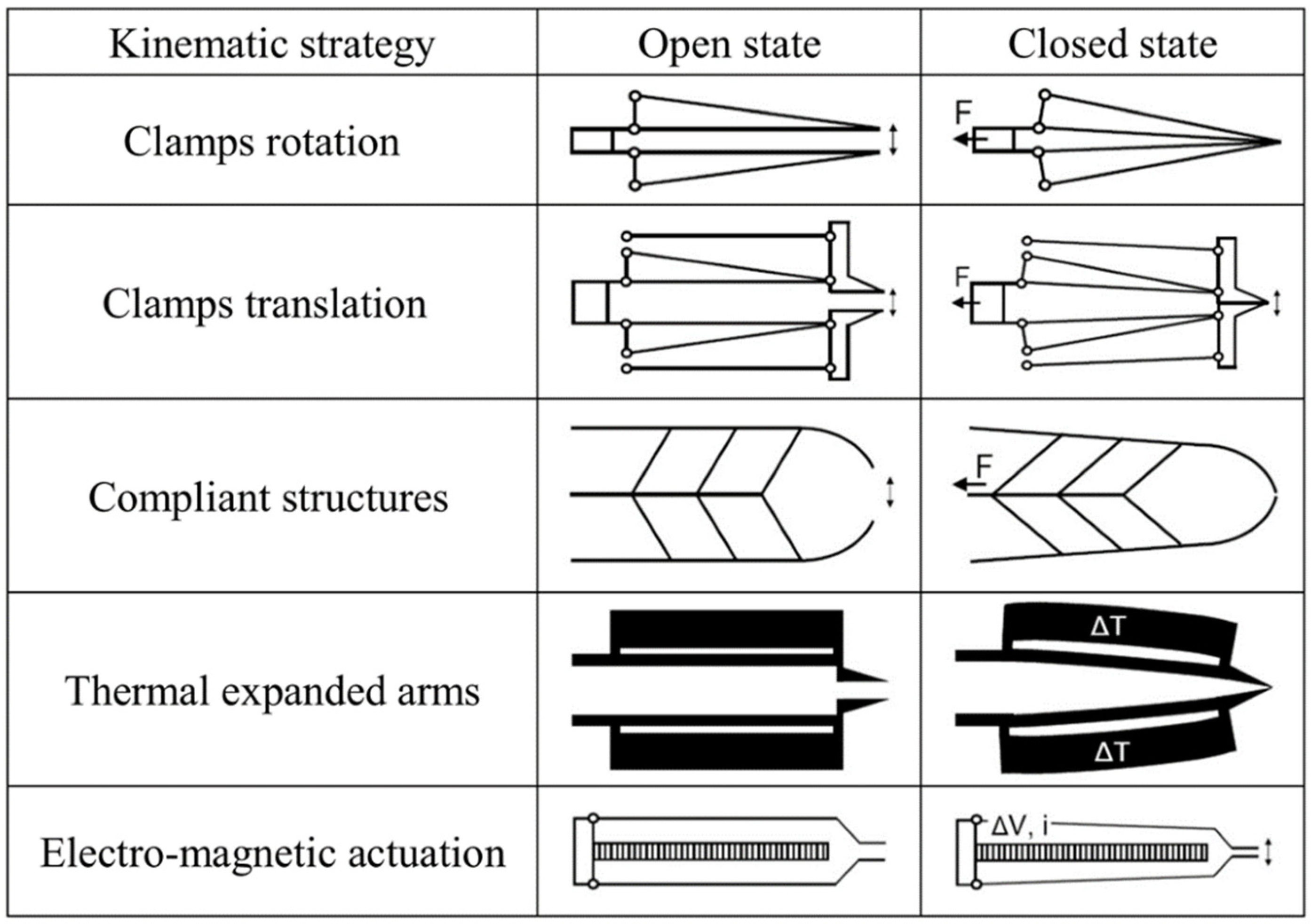
2. Microgrippers Design Criteria

From the literature analysis, the main design features of microgrippers for cell manipulation are limited to the following: (a) actuation principle, (b) kinematic principle, (c) fingertips shape, (d) force feedback, (e) releasing strategy.
The actuation principle is usually determined by selecting internal or external actuators. In the first case, the most diffused strategy consists in building some specific parts of the gripper with piezoelectric materials to generate a localized force under the application of electric voltage [49,50,51]. The electrostatic force can be used as an actuation by applying a voltage difference on a capacitor with movable armature [4]. The thermal actuation, widely used for both biological and non-biological manipulation, is based on the thermal expansion of the gripper arms due to the Joule effect in the presence of electric currents [11]. A faster response of the arms can be achieved with SMA [16]: they are able to restore almost immediately the memorized shape when a threshold temperature is passed. The electromagnetic actuation is based on micro-coils and it is able to generate weak confined magnetic fields [17]. Hydraulic and pneumatic actuation can be used to manipulate bio-cells with micro-pipes integrated in small circuits including micro-pumps and valves [52]. However, there are strong limitations in using internal actuators for the manipulation of biological particles. The piezoelectric actuators are affected by strongly nonlinear output, high supply voltage, small motion range and reliability issues such as creep, mechanical fatigue, hysteresis, and biocompatibility. The consequence of these limitations is that the use of embedded force feedback control is almost mandatory. The electrostatic actuators are disadvantaged by the small capacitor dimensions that limit the actuation force. Then, complicated shapes of the gripper are needed to increase the force, for instance by using comb drive electrodes. However, the motion range is small because it is confined inside the small armatures gap and the actuation voltage may easily induce water electrolysis and gaseous products or bubble formation. The thermal actuation is commonly used in the design of microgrippers for bio-manipulation, but it induces the heating of the region around the actuator. Some precautions must be taken to prevent the heating of arm tips and the contacting cells; for instance, long gripper arms are proposed to reduce the thermal conduction from the actuator to the tips. Regarding SMA materials, the main problem is their low fatigue resistance that causes a very limited lifetime under cyclic loads. Furthermore, SMA materials have small strain capability, strong nonlinearity and hysteresis, and their fabrication process is usually very complicated in the microscale. The limitations of electro-magnetic actuators are related to their small dimension that implies fast heating of the coil due to the Joule effect and low currents; then, the resulting magnetic field is generally weak and subjected to high leakages, giving small power per unit volume. Hydraulic and pneumatic actuators are limited to pipe based devices; usually, they are not suitable for precision operations involving more than one cell and the hydraulic solution only works in wet environments [53].
More promising opportunities for bio-cells manipulators are offered by external actuators, which preserve the thermal insulation of the gripper and avoid contamination or biocompatibility problems. The most suitable solutions are electric motors (DC motors and stepper motors) and piezoelectric motors [53]. The first category may experience undesired heat generation, relatively low motion precision, and large size for micro manipulation; furthermore, stepper motors are not able to provide smooth motion. The piezoelectric motors are the most promising solution for this application, due to their small size and high accuracy [2]; they also have very high responsiveness and wide speed range (from a few micrometers/second to few millimeters/second). The thermal heating is also negligible. The only problems are related to the interface between the motor and the microgripper, where interference and frictions must be considered. Other less investigated strategies for the internal and external actuation includes ultrasonic motors, picomotors, stick-slip and inchworm actuators. The advantages and limitations of the fundamental internal and external actuation strategies are summarized in Table 1.
Regarding the kinematic solutions reported in the literature, the number of variants is very high and often strongly linked to the specific field of application of the gripper and the actuation used. This large variety of kinematic strategies has been analyzed and reduced to a few main groups, based on the structural design principle. The result of the analysis is reported in the graphical summary of Figure 1. Differently from the other categories, the compliant structures exploit the material elasticity to transfer the force from the actuator to the cell. The force is also amplified through the geometrical characteristics and the structural deformation mode [53,54]. The solution at the basis of compliant structures is attractive for the design for AM. In fact, in this case the local structure stiffness is controllable in high detail by shaping the geometry with a few constraints. Additionally, the design for additive can provide large and shaped gripping surfaces to reduce the local pressure on the cell. Another advantage of compliant structures is the possibility to slightly adapt the shape of the fingertip to the conformation of the cell: thanks to the high deformability of the structure, it is possible to embrace the cell and to distribute almost uniformly the gripping force on its surface.
Regarding the fingertips, from the literature survey it emerged that this detail requires careful design to provide the right conformation to the grip site. In the case of low design complexity, the gripping site is limited to two opposite points on the counter fingertips. Clearly, this solution leads to a high local force that, in the case of manipulation of biological cells, can compromise the sample’s integrity. Another option, that is preferred over the first one, is represented by rigid fingertips in relative translation or rotation (i.e., the case reported in Figure 1). This solution is more effective when a proper shape of the fingertip is provided. The literature revealed that the most diffused fingertip shapes are flat, notched, and cylindrical, as represented in Figure 2 [55]. Other non-standard fingertip shapes were also proposed.
The force feedback measurement is often crucial for bio-manipulation, due to the small mechanical resistance of the cells [49,56,57,58]. The most used method is the displacement control through optical detection, which is contactless and very accurate. Other methods were explored, for instance by using integrated piezoresistive transducers or micro-capacitive sensors; however, these approaches are usually limited by the low biocompatibility of materials and the risk of water electrolysis.
The sample release from the gripper is another design issue in the case of cell manipulation, because the effect of the gravity is much smaller than the adhesion force and the capillary force acting between the contacting surfaces. The releasing strategies used in the literature are passive or active. In the first case, the gripper surface is used to provide the cell detachment through the shape, material, or coatings. In the second case, external forces, pressures, or vibrations are used [59]. A list of releasing strategies is reported in Table 2.

3. Laser-Based AM Processes

The microfabrication of an MEMS gripper is effectively supported by the AM processes based on the photopolymerization of liquid resins through a laser source. The application of these processes was limited in the past by the limitations of the in-plane resolution caused by the optical properties of the polymers used. In fact, the light refraction and diffraction are directly responsible for the quality of the so-called “transition region”, where the exposed and unexposed liquid volumes come into contact. The thickness of this region is inversely proportional to the dimensional accuracy of the final parts. By considering the micrometer scale, the liquid volume processed is relatively small and the light deviation is then proportionally reduced. Then, MEMS components with dimensions below 50 μm are easily achievable with high precision, as already demonstrated by previous works [34,60,61,62]. Instead, the dimensional accuracy is much higher by using the two-photon polymerization (TPP) process, where the pulse light generated by a laser transparent photopolymer is able to expose the resin exactly at the beam focal point, with a precision in the order of a few nanometers [63]. The design of MEMS for micro-stereolithography is characterized by high flexibility of shape freedom even for complicated geometries. The aspect ratio is generally high due to the printing strategy of layer superposition. The light diffraction may induce non-uniform thickness and the contact surface with the machine stage may induce geometrical distortion or variable curing conditions. On the other hand, the AM strategy allows the production of small volumes or even single pieces and easy operations of fine adjustment on the original design and geometries. This flexibility generally allows the correction of production issues and fast achievement of stabilized process.

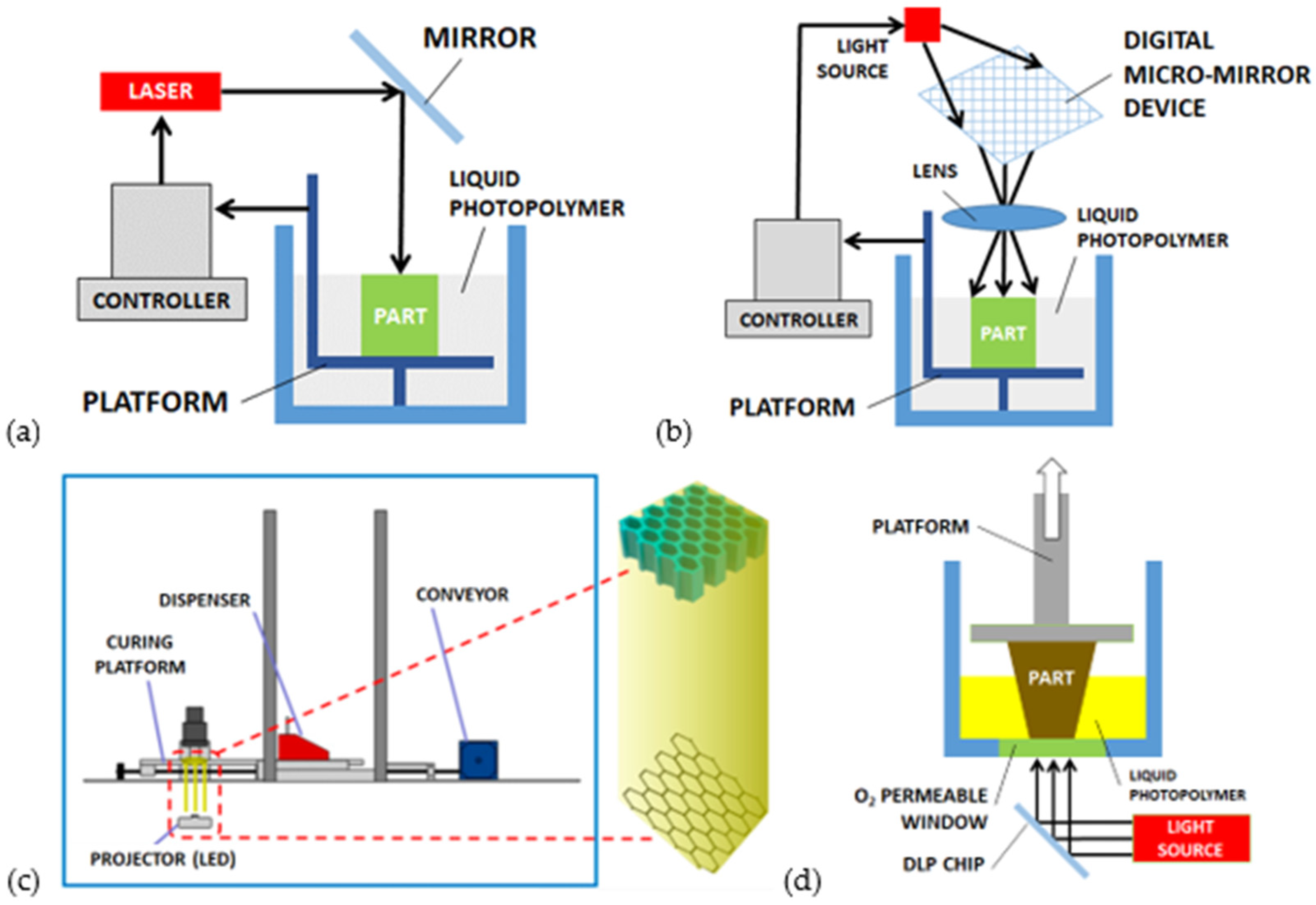
3.1. Micro-Stereolithography (μ-SLA)

In 1984, Charles W. Hull patented the system called “stereolithography apparatus” (SLA) [64] and the associated STL file format used to divide in slices the geometrical 3D models. For many years, this standard was the most diffused and cheap support to develop 3D printed parts with polymers in the macroscale [65]. The same principle, the selective exposure of a liquid photosensitive material through a laser source to induce polymerization and solidification (also called photocuring), has been extended to the micro-scale [64,66,67,68,69,70].
The micro-stereolithography, depending on the exposure strategy, is divided into scanning and light projection methods [66]. In the scanning laser stereolithography (SLSLA), as reported in Figure 3a, the laser beam produces the local polymerization of the liquid resin point-by-point on its surface. The laser pattern is defined by the digital processing of the original geometry, which is preliminarily sliced to identify the exposure areas corresponding to each layer. The thickness of each layer is in the range of 10–100 μm. The layers’ superposition is achievable thanks to a building platform that moves downwards [65]. In the projection stereolithography (PSLA) process (Figure 3b), the entire surface of the liquid photosensitive resin is exposed to the light source simultaneously. Digital micromirror devices (DMD) composed of a matrix of reflecting and orientable surfaces, individually controllable, provide the shaping of light. The DMD chip may contain several million micro-mirrors, combined together to define the entire image [65].

3.2. Mask–Image–Projection Stereolithography (MIP-SLA)

This process variant of the traditional stereolithography is represented in Figure 3c. The localized laser exposure is again responsible for the liquid resin selective polymerization but, different from the projection stereolithography, a green part is preliminarily fabricated. This green part is then used as a light mask to describe complex profiles with difficult exposure patterns. The process demonstrated reliable results in the fabrication of BaTiO3 piezoelectric composite ceramics defined by a honeycomb structure with 450 μm wall thickness [71].

3.3. Continuous Liquid Interphase Printing (CLIP)

This process is also similar to the projection stereolithography (PSLA), as reported in Figure 3d. However, the liquid resin is here contained inside a tank with a transparent bottom side, which allows the transit of ultraviolet light from the source situated below the tank. The printed object rises during the polymerization allowing other resin to flow below the exposed layer. An optically transparent membrane, permeable to oxygen, is situated below the resin [72]. The photo-polymerization is quenched by the oxygen and the membrane creates a persistent liquid interface that prevents the adhesion of the part with the pool [73].
Table 3 reports the feature size and materials associated to the AM processes described, according to the previous experiences documented in the field of MEMS fabrication.

4. Design and Modeling

The manipulation of living cells, as already mentioned, causes some constraints regarding the preservation of the samples’ integrity with effects on the selection of the actuation strategy and design solutions. The following design proposal is based on the assumption of an external actuation strategy, which is supported by the advantages described in detail in the previous sections. Then, the actuation is totally separated from the gripping arms. In addition to the mentioned reasons preserving the samples’ integrity, the external actuation leads to significant simplification of the device architecture and microfabrication. Furthermore, this separation allows the use of different typologies of actuators as the driving part of the gripper without relevant drawback on the gripper coupling and on the health of cells.
The configuration of the gripper is defined through the evolution of the original shape, by considering the microfabrication rules (growth direction, vertical drift, parts release method, etc.) and dimensional accuracy typical of the micro-stereolithography (μ-SLA) process. This process is preferred because of the established setup and the consequently higher dimensional accuracy (in the order of a few tens of micrometers). Other processes are also applicable for the fabrication of the proposed MEMS microgripper, however, they are less consolidated and wider deviation on the final geometrical precision is expected. Scaled variants of the proposed gripper are more suitable for these two last processes. For instance, the MIP-SLA process leads to accuracy in the order of a few hundred of micrometers and the CLIP process in the order of one-hundred microns.

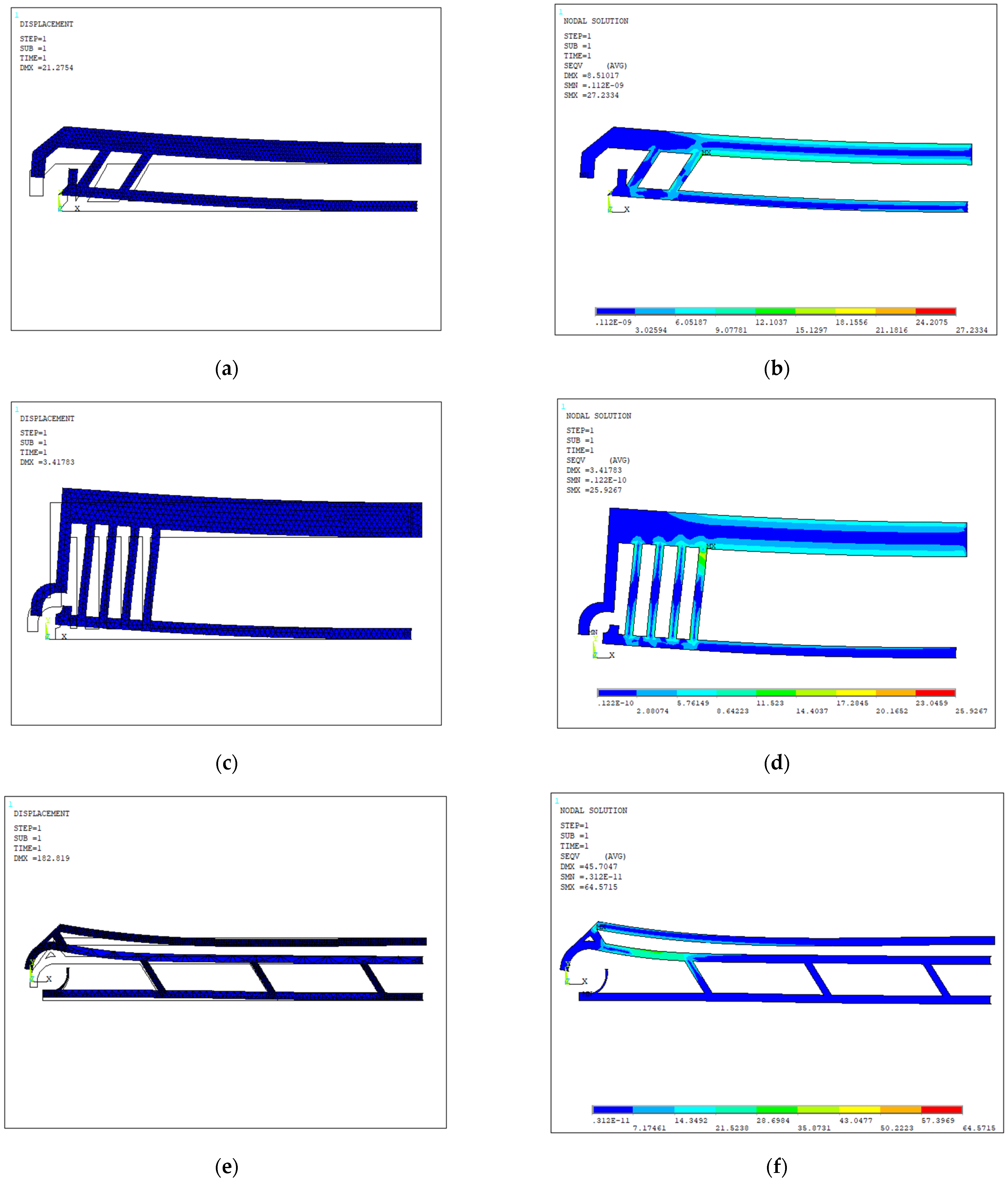
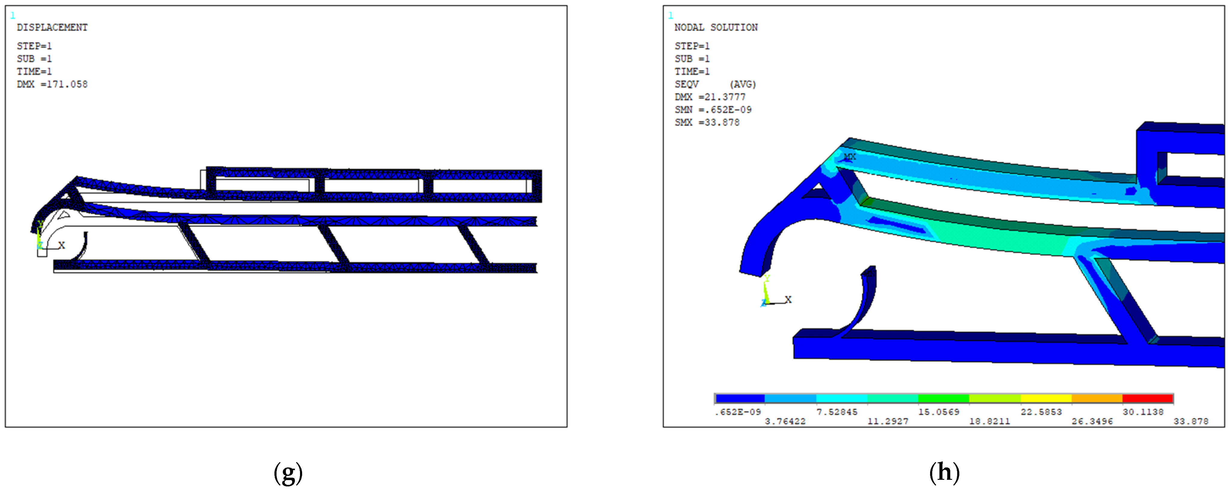
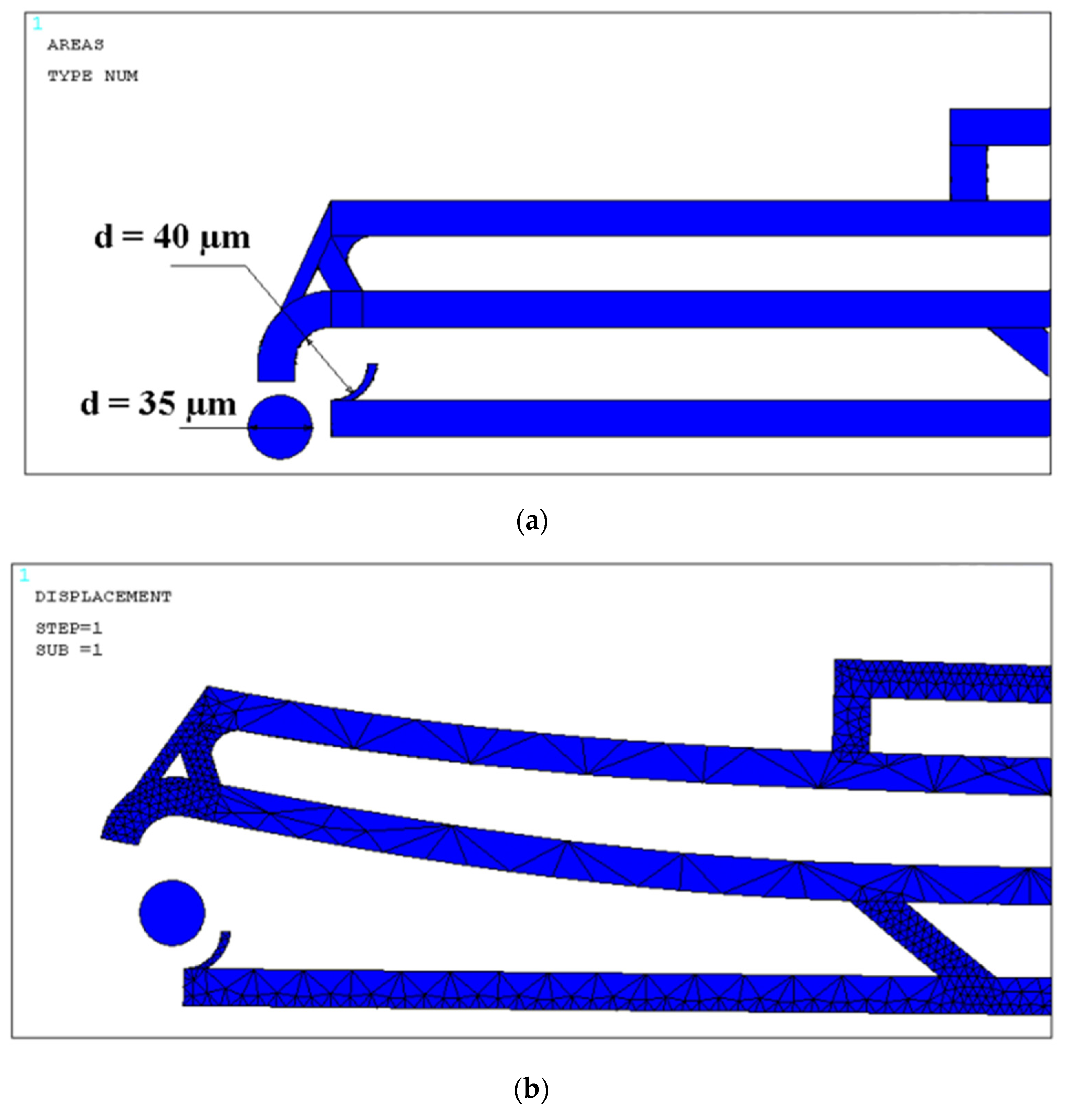
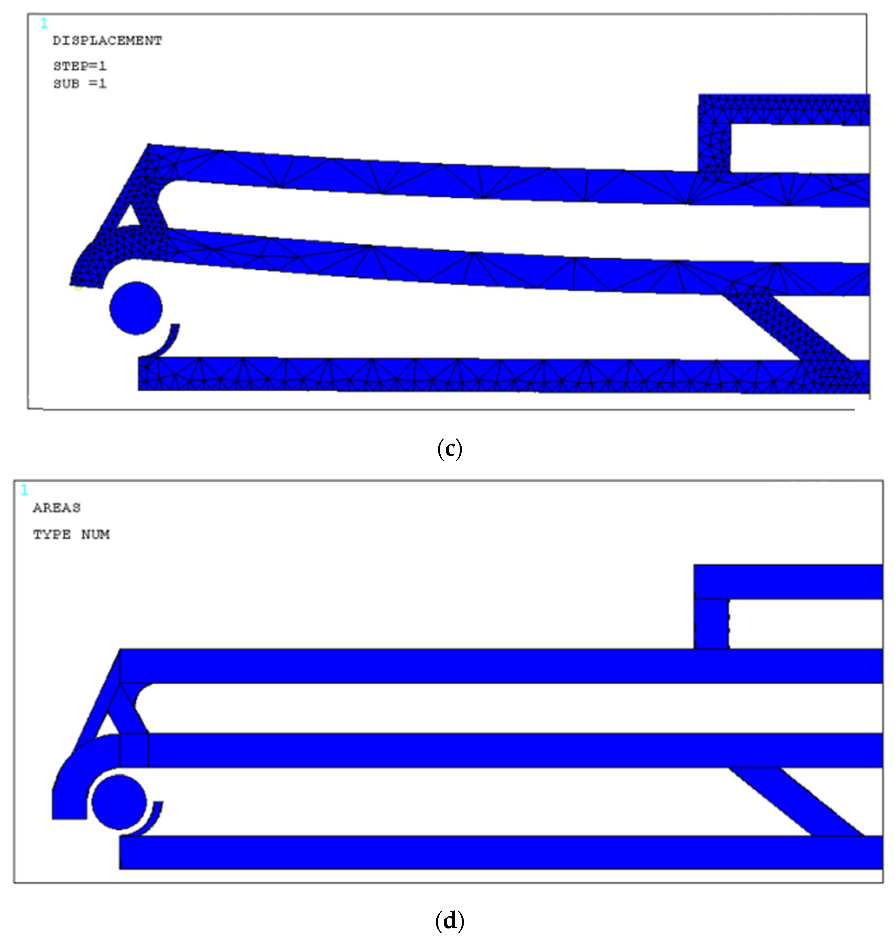
4.1. Design Optimization

The MEMS microgripper is progressively optimized as described in the design steps of Figure 4. The kinematic strategy at the basis of this device is relatively simple and highly effective. The external actuation applies an axial force on the upper arm of the micro-gripper. The structural compliance allows tip opening to host the cell sample and the device topology is optimized to reduce the stress levels and to minimize the ratio between actuation displacement and tip opening. In the proposed configuration, the fingertip shape is defined according to target cells with 35 µm diameter in this case. Different cell typologies may vary strongly in diameter size, then the fingertip can be scaled accordingly, independently from the rest of the microstructure. The maximum size of the gripper arms is 1 mm and the maximum vertical thickness is 20 µm: these dimensions are considered as constraints in the design optimization, in relation to the AM process limits. The gripper has one fixed arm and one moving arm. The displacement is applied to the moving arm by the external actuator, and the maximum values of the applied displacements are +20 µm (pulling) and −10 µm (pushing).
The MEMS microgripper static behavior is simulated through an FEM structural model. In particular, the numerical model is used to calculate the structural stiffness and to visualize the deformed elastic shape of the microgripper when the constructive parameters are changed. The design parameters subjected to optimization are the dimension and orientation of the struts of the compliant structure (length, width, and configuration). The summary of the optimization steps is reported in Table 4.
The numerical simulation is built with the ANSYS 2020R2 software simulation tool. The structural 3D model of the micro-gripper is built with tetrahedral elements SOLID92. The structure thickness is 50 μm, the mesh size varies in the range 10–30 μm along the arms, down to 2 μm at the fingertips. In the last two gripper configurations, the lower arm is fully constrained at the left end to simulate the lateral support. On the upper arm, the imposed axial displacement (between 10 and 20 μm) is used to simulate the actuation effect. The material selection is limited by the options available for AM processes and, in particular, for the μ-SLA process (including optical and other physical properties). Among the available polymers, the additional necessary properties for the addressed application are biocompatibility, flexibility, and multi-cycle reliability. The SU-8 material offers the best compromise, and it is already widely used in the traditional fabrication of MEMS microgrippers with micromachining methods [76]. The following material properties were used for the structural modeling: Young’s modulus E = 4.02 GPa, Poisson’s ratio ν = 0.22, thermal expansion coefficient α = 52 × 10−6 K−1, and ultimate tensile stress σU = 38 MPa. The maximum stress produced in the microgripper structure was evaluated during the design optimization process and the appropriate corrections were introduced to keep its value always below the ultimate stress limit.
With reference to Figure 4a, in the first layout the basic idea is to achieve the gripping task with two opposite arms connected with intermediate struts. The upper arm is fixed and the lower arm is connected to the external actuator. With this configuration, the main issue is represented by the excessive bending displacement of the device caused by the intrinsic stiffness of the entire structure. The axial and bending displacement need to be uncoupled most efficiently to achieve higher levels of usability of the gripper. Figure 4b shows the deformed and undeformed shapes and the corresponding stress distribution. The results are also reported in Table 4. By applying 20 µm displacement to the lower arm, more than 100 µm displacement in the bending direction occurs.
In the next design version (layout 2, Figure 4c,d), to solve this problem, a wider upper arm and longer intermediate struts are used. Additionally, the orientation angle of the struts is increased to amplify the axial displacement and to uncouple the bending motion. This configuration provides a beneficial effect to reduce the actuation force needed to achieve the same tips opening. The tip shape is also improved to host the cell more properly, as described before, and to fit the target cell diameter size of 35 µm. However, the results reported in Table 4 for this layout show that the original problem is still unsolved (axial and bending displacements are almost the same, around 20 µm, when the same actuation displacement is imposed on the movable arm). Even though the second configuration decreased the bending displacement with respect to the first one, the long struts increased the overall gripper size, which is not desirable.
The next solution introduced in layout 3 is represented in Figure 4e,f. Here, one additional arm is introduced, and the actuation is connected to the upper arm, while the two lower arms are fixed. This improvement leads to overall stress reduction and increased opening range of the gripper tips and higher deformation directions’ uncoupling. The only drawback is the high deflection of the upper arm occurring when the actuation displacement is applied. This effect may reduce the usability of the device because of loss of pointing precision of the gripper tips.
Then, the final design (layout 4), reported in Figure 4g,h, was implemented with another strut on the upper arm to reduce its overall deflection. Finally, a large opening of the gripper tips can be achieved in the presence of small actuation displacement (only 10 µm are imposed in the simulation, i.e., one-half of the value imposed on the first layout). As reported in Table 4, this layout reaches the maximum opening range with the minimum stress induced in the material. This is due to the lower stiffness value among the layouts and the limited gripper width (140 µm). In the same table, the actuation displacement corresponds to the opening distance of the gripper tips able to host the cell sample. The force corresponds to the elastic reaction produced by the structure, and to the force imposed by the external actuator. The vertical displacement of tips is referred to the fixed and movable arms respectively, and the vertical and horizontal opening distance between the arms is expressed with reference to the unloaded position. The overall stiffness is the ratio between the actuation force and the total tips displacement (vector composition).
Most of the grippers previously proposed are based on movable arms experiencing the rotation of their tips during the open–close motion. This means that the gripping surfaces do not maintain the same orientation during the cell manipulation. Differently from the traditional layout, the proposed solution for cell hosting is based on two opposite contact surfaces with variable distance, represented in Figure 4h. The nominal distance between the surfaces corresponds to the unloaded position of the gripper, while the opening position is associated to the actuated configuration. The two surfaces contacting the cell have a circular shape and define a closed volume that surrounds the cell in the controlled position even in the unloaded position. The additional function of this particular tip shape is the increase in the contact surface between the cell and the gripper, leading to lower contact pressure and lower loading of the cell membrane.

4.2. Operative Sequence

The gripping operation on the cell samples is composed of four steps, as represented in Figure 5: the cell approaching, the arms opening, the arms closing, and the cell gripping. With reference to the same figure, a 35 µm cell is represented ahead of the microgripper tip, after the tool approached the sample. The maximum opening of the gripper tips is represented in Figure 5b, where the deformed configuration is obtained by applying 10 µm displacement with the linear actuator by pulling the upper arm. This displacement is achieved by applying 4.2 µN force to the moving arm, corresponding to the elastic reaction force of the structure. In comparison with the other layouts (1–3), this tip opening is the highest under the same imposed displacement. This characteristic is linked to the structural stiffness, which is the lowest among the design variants. Figure 5c reports the configuration of the gripper with 2 µm actuation displacement in the closing phase. In the last configuration reported in Figure 5d, the gripper is in the unloaded condition. In this position, the two arms are in the nominal position and the cell sample is held in the confined volume provided by the two tips. The contact pressure on the cell membrane is minimized by the large surface and the flexibility of the lower contact surface (the smaller one in Figure 5d).

5. Conclusions

The proposed design methodology applied to microgrippers for cell manipulation is based on the external actuation strategy and on the micro-stereolithography process. The working principle of the microgripper is associated with structural compliance, which is optimized through parameterized modeling. The proposed solution, in particular with reference to the last step of the geometrical evolution, provides the elastic reaction force of 4.2 N in the presence of 10 μm applied displacement. The relative fingertips’ vertical opening is 35 μm and only 6 μm in the horizontal direction. The stress in the material is limited to 32 MPa in the most loaded point corresponding to the last portion of the upper arm. In comparison with the traditional micromachining fabrication processes, the micro-stereolithography does not require multi-material layer deposition, material doping, and many masks of photoresist exposure.

Funding

This research received no external funding.

Institutional Review Board Statement

Not applicable.

Informed Consent Statement

Not applicable.

Conflicts of Interest

The authors declare no conflict of interest.

References

  1. Zubir, M.N.M.; Shirinzadeh, B.; Tian, Y. A New Design of Piezoelectric Driven Compliant-Based Microgripper for Micromanipulation. Mech. Mach. Theory 2009, 44, 2248–2264. [Google Scholar] [CrossRef]
  2. Nah, S.K.; Zhong, Z.W. A Microgripper Using Piezoelectric Actuation for Micro-Object Manipulation. Sens. Actuators A Phys. 2007, 133, 218–224. [Google Scholar] [CrossRef]
  3. Verotti, M.; Di Giamberardino, P.; Belfiore, N.P.; Giannini, O. A Genetic Algorithm-Based Method for the Mechanical Characterization of Biosamples Using a MEMS Microgripper: Numerical Simulations. J. Mech. Behav. Biomed. Mater. 2019, 96, 88–95. [Google Scholar] [CrossRef] [PubMed]
  4. Beyeler, F.; Neild, A.; Oberti, S.; Bell, D.J.; Sun, Y.; Dual, J.; Nelson, B.J. Monolithically Fabricated Microgripper with Integrated Force Sensor for Manipulating Microobjects and Biological Cells Aligned in an Ultrasonic Field. J. Microelectromech. Syst. 2007, 16, 7–15. [Google Scholar] [CrossRef]
  5. Chen, T.; Sun, L.; Chen, L.; Rong, W.; Li, X. A Hybrid-Type Electrostatically Driven Microgripper with an Integrated Vacuum Tool. Sens. Actuators A Phys. 2010, 158, 320–327. [Google Scholar] [CrossRef]
  6. Volland, B.E.; Ivanova, K.; Ivanov, T.; Sarov, Y.; Guliyev, E.; Persaud, A.; Zöllner, J.P.; Klett, S.; Kostic, I.; Rangelow, I.W. Duo-Action Electro Thermal Micro Gripper. Microelectron. Eng. 2007, 84, 1329–1332. [Google Scholar] [CrossRef]
  7. Vurchio, F.; Fiori, G.; Scorza, A.; Sciuto, S.A. Comparative Evaluation of Three Image Analysis Methods for Angular Displacement Measurement in a MEMS Microgripper Prototype: A Preliminary Study. Acta IMEKO 2021, 10, 119–125. [Google Scholar] [CrossRef]
  8. Belfiore, N.P.; Bagolini, A.; Rossi, A.; Bocchetta, G.; Vurchio, F.; Crescenzi, R.; Scorza, A.; Bellutti, P.; Sciuto, S.A. Design, Fabrication, Testing and Simulation of a Rotary Double Comb Drives Actuated Microgripper. Micromachines 2021, 12, 1263. [Google Scholar] [CrossRef]
  9. Andersen, K.N.; Carlson, K.; Petersen, D.H.; Mølhave, K.; Eichhorn, V.; Fatikow, S.; Bøggild, P. Electrothermal Microgrippers for Pick-and-Place Operations. Microelectron. Eng. 2008, 85, 1128–1130. [Google Scholar] [CrossRef]
  10. Ivanova, K.; Ivanov, T.; Badar, A.; Volland, B.E.; Rangelow, I.W.; Andrijasevic, D.; Sümecz, F.; Fischer, S.; Spitzbart, M.; Brenner, W.; et al. Thermally Driven Microgripper as a Tool for Micro Assembly. Microelectron. Eng. 2006, 83, 1393–1395. [Google Scholar] [CrossRef]
  11. Nguyen, N.T.; Ho, S.S.; Low, C.L.N. A Polymeric Microgripper with Integrated Thermal Actuators. J. Micromech. Microeng. 2004, 14, 969–974. [Google Scholar] [CrossRef]
  12. Roy, A.; Nabi, M. Modeling of MEMS Electrothermal Microgripper Employing POD-DEIM and POD Method. Microelectron. Reliab. 2021, 125, 114338. [Google Scholar] [CrossRef]
  13. Roy, A.; Sarkar, R.; Banerjee, A.; Nabi, M. An Efficient Design Procedure for MEMS Electrothermal Microgripper. ASME Lett. Dyn. Syst. Control 2021, 2, 1–6. [Google Scholar] [CrossRef]
  14. Huang, W. On the Selection of Shape Memory Alloys for Actuators. Mater. Des. 2002, 23, 11–19. [Google Scholar] [CrossRef]
  15. Kohl, M.; Skrobanek, K.D. Linear Microactuators Based on the Shape Memory Effect. Sens. Actuators A Phys. 1998, 70, 104–111. [Google Scholar] [CrossRef]
  16. Kohl, M.; Krevet, B.; Just, E. SMA Microgripper System. Sens. Actuators A Phys. 2002, 97–98, 646–652. [Google Scholar] [CrossRef]
  17. Giouroudi, I.; Hötzendorfer, H.; Kosel, J.; Andrijasevic, D.; Brenner, W. Development of a Microgripping System for Handling of Microcomponents. Precis. Eng. 2008, 32, 148–152. [Google Scholar] [CrossRef]
  18. Suriyage, M.P.; Prabath, T.A.B.; Wickramathilaka, Y.L.G.C.L.; Silva, S.K.M.M.; Gunawardane, M.A.S.V.; Jayawardana, J.A.D.N.; Bandara, H.M.N.W.; Withanapathirana, W.P.V.V.; Amarasinghe, Y.W.R. Design of a Novel Mems-Based Microgripper with Hybrid Actuation to Determine Circulating Tumor Cell (CTC) Progression. In Innovation in Medicine and Healthcare; Chen, Y.W., Tanaka, S., Howlett, R., Jain, L., Eds.; Smart Innovation, Systems and Technologies; Springer: Singapore, 2020; Volume 192. [Google Scholar]
  19. Majidi Fard-Vatan, H.; Hamedi, M. Design, Analysis and Fabrication of a Novel Hybrid Electrothermal Microgripper in Microassembly Cell. Microelectron. Eng. 2020, 231, 111374. [Google Scholar] [CrossRef]
  20. Wei, D.; Hall, M.B.; Sherehiy, A.; Popa, D.O. Design and Evaluation of Human-Machine Interface for NEXUS: A Custom Microassembly System. J. Micro Nano-Manuf. 2020, 8, 041011. [Google Scholar] [CrossRef]
  21. Kim, J.W.; Yoshida, K.; Ide, T.; Yokota, S. Fabrication, Experiment, and Simulation of a Flexible Microvalve-Integrated Microarm for Microgrippers Using Electrorheological Fluid. J. Robot. Mechatron. 2020, 32, 333–343. [Google Scholar] [CrossRef]
  22. Chronis, N.; Lee, L.P. Electrothermally Activated SU-8 Microgripper for Single Cell Manipulation in Solution. J. Microelectromech. Syst. 2005, 14, 857–863. [Google Scholar] [CrossRef]
  23. Han, K.; Lee, S.H.; Moon, W.; Park, J.S. Fabrication of the Micro-Gripper with a Force Sensor for Manipulating a Cell. In Proceedings of the 2006 SICE-ICASE International Joint Conference, Busan, Korea, 18–21 October 2006. [Google Scholar]
  24. Neagu, C.; Jansen, H.; Gardeniers, H.; Elwenspoek, M. Electrolysis of Water: An Actuation Principle for MEMS with a Big Opportunity. Mechatronics 2000, 10, 571–581. [Google Scholar] [CrossRef]
  25. Vurchio, F.; Fiori, G.; Scorza, A.; Sciuto, S.A. A Comparison among Three Different Image Analysis Methods for the Displacement Measurement in a Novel MEMS Device. In Proceedings of the 24th IMEKO TC4 International Symposium and 22nd International Workshop on ADC and DAC Modelling and Testing, Palermo, Italy, 14–16 September 2020. [Google Scholar]
  26. Vurchio, F.; Orsini, F.; Scorza, A.; Fuiano, F.; Sciuto, S.A. A Preliminary Study on a Novel Automatic Method for Angular Displacement Measurements in Microgripper for Biomedical Applications. In Proceedings of the 2020 IEEE International Symposium on Medical Measurements and Applications (MeMeA), Bari, Italy, 1 June–1 July 2020. [Google Scholar]
  27. Schindler, C.B.; Gomez, H.C.; Acker-James, D.; Teal, D.; Li, W.; Pister, K.S.J. 15 Millinewton Force, 1 Millimeter Displacement, Low-Power MEMS Gripper. In Proceedings of the IEEE International Conference on Micro Electro Mechanical Systems (MEMS), Vancouver, BC, Canada, 18–22 January 2020. [Google Scholar]
  28. Ferrara-Bello, A.; Vargas-Chable, P.; Vera-Dimas, G.; Vargas-Bernal, R.; Tecpoyotl-Torres, M. XYZ Micropositioning System Based on Compliance Mechanisms Fabricated by Additive Manufacturing. Actuators 2021, 10, 68. [Google Scholar] [CrossRef]
  29. Li, W.J.; Xi, N. Novel Micro Gripping, Probing, and Sensing Devices for Single-Cell Surgery. In Proceedings of the Annual International Conference of the IEEE Engineering in Medicine and Biology Society, San Francisco, CA, USA, 1–5 September 2004; Volume 26 IV. [Google Scholar]
  30. Solano, B.; Wood, D. Design and Testing of a Polymeric Microgripper for Cell Manipulation. Microelectron. Eng. 2007, 84, 1219–1222. [Google Scholar] [CrossRef]
  31. MacKay, R.E.; Le, H.R.; Donnelly, K.; Keatch, R.P. Micro-Gripping of Small Scale Tissues. In Proceedings of the 4th European Conference of the International Federation for Medical and Biological Engineering. IFMBE Proceedings; Vander Sloten, J., Verdonck, P., Nyssen, M., Haueisen, J., Eds.; Springer: Berlin/Heidelberg, Germany, 2009; Volume 22. [Google Scholar]
  32. Sochol, R.D.; Sweet, E.; Glick, C.C.; Wu, S.Y.; Yang, C.; Restaino, M.; Lin, L. 3D Printed Microfluidics and Microelectronics. Microelectron. Eng. 2018, 189, 52–68. [Google Scholar] [CrossRef]
  33. Rupal, B.S.; Garcia, E.A.; Ayranci, C.; Qureshi, A.J. 3D Printed 3D-Microfluidics: Recent Developments and Design Challenges. J. Integr. Des. Process Sci. 2019, 22, 5–20. [Google Scholar] [CrossRef]
  34. Lifton, V.A.; Lifton, G.; Simon, S. Options for Additive Rapid Prototyping Methods (3D Printing) in MEMS Technology. Rapid Prototyp. J. 2014, 20, 403–412. [Google Scholar] [CrossRef]
  35. Vaezi, M.; Seitz, H.; Yang, S. A Review on 3D Micro-Additive Manufacturing Technologies. Int. J. Adv. Manuf. Technol. 2013, 67, 1721–1754. [Google Scholar] [CrossRef]
  36. ISO/ASTM 52900:2015(E); Standard Terminology for Additive Manufacturing—General Principles—Terminology; International Organization for Standardization: Geneva, Switzerland, 2015; pp. 1–9.
  37. Kamat, A.M.; Pei, Y.; Jayawardhana, B.; Kottapalli, A.G.P. Biomimetic Soft Polymer Microstructures and Piezoresistive Graphene MEMS Sensors Using Sacrificial Metal 3D Printing. ACS Appl. Mater. Interfaces 2021, 13, 1094–1104. [Google Scholar] [CrossRef]
  38. Ligon, S.C.; Liska, R.; Stampfl, J.; Gurr, M.; Mülhaupt, R. Polymers for 3D Printing and Customized Additive Manufacturing. Chem. Rev. 2017, 117, 10212–10290. [Google Scholar] [CrossRef] [Green Version]
  39. Wegst, U.G.K.; Bai, H.; Saiz, E.; Tomsia, A.P.; Ritchie, R.O. Bioinspired Structural Materials. Nat. Mater. 2015, 14, 23–36. [Google Scholar] [CrossRef] [PubMed]
  40. Ovsianikov, A.; Khademhosseini, A.; Mironov, V. The Synergy of Scaffold-Based and Scaffold-Free Tissue Engineering Strategies. Trends Biotechnol. 2018, 36, 348–357. [Google Scholar] [CrossRef] [PubMed]
  41. De Pasquale, G.; Ruggeri, V. Sensing Strategies in Wearable Bio-Mechanical Systems for Medicine and Sport: A Review. J. Micromech. Microeng. 2019, 29, 103001. [Google Scholar] [CrossRef]
  42. Duan, B. State-of-the-Art Review of 3D Bioprinting for Cardiovascular Tissue Engineering. Ann. Biomed. Eng. 2017, 45, 195–209. [Google Scholar] [CrossRef] [PubMed]
  43. Zhang, Y.S.; Yue, K.; Aleman, J.; Mollazadeh-Moghaddam, K.; Bakht, S.M.; Yang, J.; Jia, W.; Dell’Erba, V.; Assawes, P.; Shin, S.R.; et al. 3D Bioprinting for Tissue and Organ Fabrication. Ann. Biomed. Eng. 2017, 45, 148–163. [Google Scholar] [CrossRef] [Green Version]
  44. Joshi, S.; Cook, E.; Mannoor, M.S. Bacterial Nanobionics via 3D Printing. Nano Lett. 2018, 18, 7448–7456. [Google Scholar] [CrossRef]
  45. Park, M.; Do, K.; Kim, J.; Son, D.; Koo, J.H.; Park, J.; Song, J.-K.; Kim, J.H.; Lee, M.; Hyeon, T.; et al. Skin Electronics: Oxide Nanomembrane Hybrids with Enhanced Mechano- and Thermo-Sensitivity for Semitransparent Epidermal Electronics (Adv. Healthcare Mater. 7/2015). Adv. Healthc. Mater. 2015, 4, 991. [Google Scholar] [CrossRef] [Green Version]
  46. Kanao, K.; Harada, S.; Yamamoto, Y.; Honda, W.; Arie, T.; Akita, S.; Takei, K. Printable Flexible Tactile Pressure and Temperature Sensors with High Selectivity against Bending. In Proceedings of the IEEE International Conference on Micro Electro Mechanical Systems (MEMS), Estoril, Portugal, 18–22 January 2015. [Google Scholar]
  47. Kong, Y.L.; Gupta, M.K.; Johnson, B.N.; McAlpine, M.C. 3D Printed Bionic Nanodevices. Nano Today 2016, 11, 330–350. [Google Scholar] [CrossRef] [Green Version]
  48. Yazdi, A.A.; Popma, A.; Wong, W.; Nguyen, T.; Pan, Y.; Xu, J. 3D Printing: An Emerging Tool for Novel Microfluidics and Lab-on-a-Chip Applications. Microfluid. Nanofluid. 2016, 20, 1–18. [Google Scholar] [CrossRef]
  49. Pérez, R.; Chaillet, N.; Domanski, K.; Janus, P.; Grabiec, P. Fabrication, Modeling and Integration of a Silicon Technology Force Sensor in a Piezoelectric Micro-Manipulator. Sens. Actuators A Phys. 2006, 128, 367–375. [Google Scholar] [CrossRef] [Green Version]
  50. De Pasquale, G. Experimental Analysis of Viscous and Material Damping in Microstructures through the Interferometric Microscopy Technique with Climatic Chamber. J. Sound Vib. 2013, 332, 4103–4121. [Google Scholar] [CrossRef] [Green Version]
  51. De Pasquale, G.; Veijola, T. Comparative Numerical Study of FEM Methods Solving Gas Damping in Perforated MEMS Devices. Microfluid. Nanofluid. 2008, 5, 517–528. [Google Scholar] [CrossRef]
  52. Seidemann, V.; Bütefisch, S.; Büttgenbach, S. Fabrication and Investigation of In-Plane Compliant SU8 Structures for MEMS and Their Application to Micro Valves and Micro Grippers. Sens. Actuators A Phys. 2002, 97–98, 457–461. [Google Scholar] [CrossRef]
  53. Ouyang, P.R.; Tjiptoprodjo, R.C.; Zhang, W.J.; Yang, G.S. Micro-Motion Devices Technology: The State of Arts Review. Int. J. Adv. Manuf. Technol. 2008, 38, 463–478. [Google Scholar] [CrossRef]
  54. Potekhina, A.; Voicu, R.C.; Muller, R.; Al-Zandi, M.H.M.; Wang, C. Design and Characterization of a Polymer Electrothermal Microgripper with a Polynomial Flexure for Efficient Operation and Studies of Moisture Effect on Negative Deflection. Microsyst. Technol. 2021, 27, 2723–2731. [Google Scholar] [CrossRef]
  55. Pedrazzoli, P.; Rinaldi, R.; Boër, C.R. A Rule Based Approach to the Gripper Selection Issue for the Assembly Process. In Proceedings of the IEEE International Symposium on Assembly and Task Planning, Fukuoka, Japan, 29 May 2001. [Google Scholar]
  56. Fahlbusch, S.; Fatikow, S. Implementation of Self-Sensing SPM Cantilevers for Nano-Force Measurement in Microrobotics. Ultramicroscopy 2001, 86, 181–190. [Google Scholar] [CrossRef]
  57. Liu, X.; Kim, K.; Zhang, Y.; Sun, Y. Nanonewton Force Sensing and Control in Microrobotic Cell Manipulation. Int. J. Rob. Res. 2009, 28, 1065–1076. [Google Scholar] [CrossRef]
  58. Carrozza, M.C.; Eisinberg, A.; Menciassi, A.; Campolo, D.; Micera, S.; Dario, P. Towards a Force-Controlled Microgripper for Assembling Biomedical Microdevices. J. Micromech. Microeng. 2000, 10, 271–276. [Google Scholar] [CrossRef]
  59. Fantoni, G.; Porta, M. A Critical Review of Releasing Strategies in Microparts Handling. In Micro-Assembly Technologies and Applications. IPAS 2008. IFIP—International Federation for Information Processing; Ratchev, S., Koelemeijer, S., Eds.; Springer: Boston, MA, USA, 2008; Volume 260. [Google Scholar]
  60. Hoxhold, B.; Büttgenbach, S. Easily Manageable, Electrothermally Actuated Silicon Micro Gripper. Microsyst. Technol. 2010, 16, 1609–1617. [Google Scholar] [CrossRef]
  61. Sun, C.; Fang, N.; Wu, D.M.; Zhang, X. Projection Micro-Stereolithography Using Digital Micro-Mirror Dynamic Mask. Sens. Actuators A Phys. 2005, 121, 113–120. [Google Scholar] [CrossRef]
  62. Zhang, X.; Jiang, X.N.; Sun, C. Micro-Stereolithography for MEMS. In Proceedings of the ASME 1998 International Mechanical Engineering Congress and Exposition. Micro-Electro-Mechanical Systems (MEMS), Anaheim, CA, USA, 15–20 November 1998; pp. 3–9. [Google Scholar] [CrossRef]
  63. De Pasquale, G. Additive Manufacturing of Micro-electro-mechanical Systems (MEMS). Micromachines 2021, 12, 1374. [Google Scholar] [CrossRef] [PubMed]
  64. Hull, C.W. Apparatus for Production of Three-Dimensional Objects by Stereolithography. U.S. Patent No 4,575,300, 8 August 1984. [Google Scholar]
  65. Fritzler, K.B.; Prinz, V.Y. 3D Printing Methods for Micro- and Nanostructures. Uspekhi Fiz. Nauk 2019, 189, 55–71. [Google Scholar] [CrossRef]
  66. Bártolo, P.J. Stereolithography—Materials, Processes and Applications; Springer Science & Business Media: Boston, MA, USA, 2011. [Google Scholar] [CrossRef]
  67. Gibson, I.; Rosen, D.; Stucker, B. Additive Manufacturing Technologies: 3D Printing and Direct Digital Manufacturing; Springer: New York, NY, USA, 2015; Volume 59, pp. 94–97. [Google Scholar]
  68. De Pasquale, G.; Bertana, V.; Scaltrito, L. Experimental Evaluation of Mechanical Properties Repeatability of SLA Polymers for Labs-on-Chip and Bio-MEMS. Microsyst. Technol. 2018, 24, 3487–3497. [Google Scholar] [CrossRef]
  69. De Pasquale, G.; Zappulla, L.; Scaltrito, L.; Bertana, V. Numerical and Experimental Evaluation of SLA Polymers Adhesion for Innovative Bio-MEMS. Mater. Today Proc. 2019, 7, 572–577. [Google Scholar] [CrossRef]
  70. Bertana, V.; De Pasquale, G.; Ferrero, S.; Scaltrito, L.; Catania, F.; Nicosia, C.; Marasso, S.L.; Cocuzza, M.; Perrucci, F. 3D Printing with the Commercial UV-Curable Standard Blend Resin: Optimized Process Parameters towards the Fabrication of Tiny Functional Parts. Polymers 2019, 11, 292. [Google Scholar] [CrossRef] [PubMed] [Green Version]
  71. Zeng, Y.; Jiang, L.; Sun, Y.; Yang, Y.; Quan, Y.; Wei, S.; Lu, G.; Li, R.; Rong, J.; Chen, Y.; et al. 3D-Printing Piezoelectric Composite with Honeycomb Structure for Ultrasonic Devices. Micromachines 2020, 11, 713. [Google Scholar] [CrossRef]
  72. Janusziewicz, R.; Tumbleston, J.R.; Quintanilla, A.L.; Mecham, S.J.; DeSimone, J.M. Layerless Fabrication with Continuous Liquid Interface Production. Proc. Natl. Acad. Sci. USA 2016, 113, 11703–11708. [Google Scholar] [CrossRef] [Green Version]
  73. Tumbleston, J.R.; Shirvanyants, D.; Ermoshkin, N.; Janusziewicz, R.; Johnson, A.R.; Kelly, D.; Chen, K.; Pinschmidt, R.; Rolland, J.P.; Ermoshkin, A.; et al. Continuous Liquid Interface Production of 3D Objects. Science 2015, 347, 1349–1352. [Google Scholar] [CrossRef]
  74. Wang, Z.; Abdulla, R.; Parker, B.; Samanipour, R.; Ghosh, S.; Kim, K. A Simple and High-Resolution Stereolithography-Based 3D Bioprinting System Using Visible Light Crosslinkable Bioinks. Biofabrication 2015, 7, 045009. [Google Scholar] [CrossRef]
  75. Knowlton, S.; Yu, C.H.; Ersoy, F.; Emadi, S.; Khademhosseini, A.; Tasoglu, S. 3D-Printed Microfluidic Chips with Patterned, Cell-Laden Hydrogel Constructs. Biofabrication 2016, 8, 025019. [Google Scholar] [CrossRef] [Green Version]
  76. Soltanzadeh, R.; Afsharipour, E.; Anssari, N.; Mansouri, B.; Shafai, C. Structural and Performance Comparison between SU-8 Microfabricated and 3D-Printed Microneedle Electrodes. J. 3D Print. Med. 2020, 4, 29–44. [Google Scholar] [CrossRef]
Figure 1. Fundamental groups of kinematic strategies used in microgrippers for cell manipulation.
Micro 02 00015 g001
Figure 2. Categories of fingertip shapes in microgrippers for cell manipulation.
Micro 02 00015 g002
Figure 3. Working principles of laser-based AM processes for polymers usable for MEMS microgripper fabrication [63]: (a) scanning and (b) projection micro-stereolithography (μ-SLA), (c) mask–image–projection stereolithography with a 3D mask (MIP-SLA) [71], and (d) continuous liquid interphase printing (CLIP).
Micro 02 00015 g003
Figure 4. Design optimization steps of the MEMS microgripper: deformed shape and stress distribution for layout 1 (a,b), layout 2 (c,d), layout 3 (e,f), and layout 4 (g,h).
Micro 02 00015 g004aMicro 02 00015 g004b
Figure 5. Sequence of operations: approaching the cell (a), opening (b), closing (c), and gripping in the unloaded configuration (d).
Micro 02 00015 g005aMicro 02 00015 g005b
Table 1. Actuation strategies used in microgrippers for cell manipulation and relative advantages and limitations.
Actuation StrategyAdvantagesLimitations
Internal actuationPiezoelectricThermal stability, high accuracy, high responsiveness.Nonlinearity, high supply voltage, small motion range, creep, fatigue, hysteresis, low biocompatibility.
Electrostatic capacitiveConsolidated micromachining manufacturing process, direct motion feedback.Complicated geometry, small motion range, electrolysis, and bubble formation.
ThermalConsolidated micromachining manufacturing process.High temperature, slow response.
SMA actuatorsFaster response then thermal actuation, large motion range.Fatigue, small motion range, nonlinearity, hysteresis, hard manufacturing process, high cost.
ElectromagneticPreservation of cell integrity.Coil heating, magnetic field weakness, field leakage.
Hydraulic and pneumaticReliability, preservation of cell integrity.Limited applicability.
External actuationDC motorsThermal insulation, high speed, high accuracy.Heat generation, dimensions, hysteresis, interface connection, feedback control needed.
Step motorsThermal insulation, very large motion range.Heat generation, low precision, dimensions, unsmooth motion, interface connection, noise.
Piezoelectric motorsLarge force, high accuracy, high responsiveness, thermal insulation, small size, no wear and tear, low power consumption.Interface connection.
Table 2. Releasing strategies used in microgrippers for cell manipulation.
Releasing StrategyDescription
Passive releaseRough surfacesThe contact area is reduced by roughness, and the electrostatic adhesion force also reduces.
Hydrophobic coatingThe coating reduces the superficial tension.
Conductive coatingConductive coatings/materials reduce the electrostatic forces through the small potential difference with the gripped object.
Vacuum environmentThe vacuum reduces the superficial tension.
Fluid environmentThe fluid eliminates the superficial tension and reduces the electrostatic forces.
Ionized airThe ionized air reduces the electrostatic forces.
Active releaseVibrationsThe acceleration imposed produces the object release due to inertial force.
Air pressureA pressurized airflow is used to overcome the adhesion force.
HeatingThe temperature reduces the capillary forces.
Electrostatic controlThe electrostatic force is controlled by shorting the gripper electrodes or by inverting the polarity.
Adhesion to the substrateThe object adheres to an external substrate by means of higher adhesion forces, by gluing it, or by engaging it on the substrate.
Additional toolsAdditional tools are used to detach the object.
Table 3. Dimensional accuracy and suitable materials of AM processes for polymer MEMS microgripper fabrication.
Laser-Based Process for MEMS Microgripper FabricationMin. Feature (μm)MaterialsReferences
Micro-stereolithography (μ-SLA)30–70Photosensitive polymers, Formlabs clear resin[74,75]
Mask–image–projection stereolithography (MIP-SLA)450Photosensitive polymers[71]
Continuous liquid interphase printing (CLIP)100Photosensitive polymers[72,73]
Table 4. Structural properties of the MEMS microgripper during the design optimization process as a result of FEM simulations with reference to the layouts from 1 to 4.
LayoutDimensions
(µm)
Width Open-Close States
(µm)
Actuated
Arm
Actuation
Displ.
Applied a
(µm)
Force
(µN)
Vertical Tips Displ. (Fixed Arm, Moving Arm)Opening Distance (Vert.) b
(µm)
Opening Distance (Horiz.) b
(µm)
Overall
Stiffness
(µN/µm)
Max
Stress
(Mpa)
11000 × 127 × 2040–18Lower−2028(106, 102)+4−103.133.93
21000 × 390 × 20100–20Lower−2025(20, 19)+1−102.632.94
31000 × 70 × 2030–5Upper105.5(4, 42)+38+0.50.1430.95
41000 × 140 × 2030–5Upper104.2(5, 41)+35+60.1132.55
a Positive = pulling actuation. Negative = pushing actuation. b With reference to the unloaded position.
Publisher’s Note: MDPI stays neutral with regard to jurisdictional claims in published maps and institutional affiliations.

