Article

UHF RFID-Based Vehicle Navigation on Straight Unpaved Road Reinforced with Geocell

by
Gabriela Maria Castro Gonzalez
1,
Takayuki Kawaguchi
2,
Dai Nakamura
2,
Kenji Kurokawa
3 and
Takeshi Kawamura
3,*
1
Co-Creative Engineering, Doctoral Program, Graduate School of Engineering, Kitami Institute of Technology, Kitami 090-8507, Japan
2
Social Environment Engineering, Kitami Institute of Technology, Kitami 090-8507, Japan
3
Information and Communications Engineering, Kitami Institute of Technology, Kitami 090-8507, Japan
*
Author to whom correspondence should be addressed.
Future Transp. 2025, 5(4), 143; https://doi.org/10.3390/futuretransp5040143
Submission received: 8 August 2025 / Revised: 21 September 2025 / Accepted: 13 October 2025 / Published: 14 October 2025

Abstract

Visibility on roads can be poor during winters owing to snowstorms and other factors. Optical devices, including Light Detection and Ranging devices, are ineffective under whiteout conditions. Moreover, buildings, trees, and other obstacles reduce the accuracy of the Global Positioning System. Therefore, we investigate vehicle navigation using an Ultrahigh Frequency Radio Frequency Identification (RFID) system. This study extends a previously developed RFID-based navigation system for paved roads to unpaved roads. Unpaved roads, particularly those in mountainous or forested areas, can become unstable because of weather conditions and present unique challenges regarding the stability of RFID tags. We use geocells to provide road stability and maintain the RFID tags at the ideal position and attitude. We insert RFID tags into polyvinyl chloride pipe holders and attach them to geocells. We also use the vehicle heading angle from the inertial navigation system (INS). In some areas, the INS is disturbed and shows incorrect direction. We utilize the RFID tag reading history to improve vehicle positioning accuracy by compensating for errors in the INS. Applying this correction reduces the average deviation from the lane center. Driving experiments are conducted on a straight unpaved road, and good results are obtained. These results validate the robustness of the proposed vehicle navigation system, which combines an RFID system with a geocell, providing insights into its successful implementation on unpaved roads.

1. Introduction

Vehicular accidents are a major issue in Hokkaido during winter as vehicles tend to drive outside their lanes because of the poor visibility caused by snowstorms and other low-visibility conditions. To address this, several companies have developed self-driving technologies using advanced systems. However, these technologies have certain limitations; for instance, optical devices cannot detect objects during whiteout conditions caused by snowstorms, and multipath interference in mountainous areas reduces GPS accuracy and affects their overall reliability [1].
Considering the characteristics of countries where it snows, we examined the effectiveness of a vehicle navigation system using an Ultrahigh Frequency (UHF) RFID system on paved roads to withstand heavy snowfall during winters [1]. Initially, three RFID tags were buried in rows, spaced 2 m apart. In our study, we placed the tags at 2-m intervals. The vehicle is approximately 4 m long. By using half of its length as a reference, we can ensure that the vehicle remains within the lane and can read the next tag before going out of the lane. Here, the number of tags had to be increased depending on the lane length. Therefore, more RFID tags were buried with the increase in lane length. To reduce costs, the number of RFID tags was decreased by using a new system, wherein one tag is buried per row and four RFID antennas are mounted on the vehicle [2].
In this study, we extend this vehicle navigation system designed for paved roads and implement it for unpaved roads. According to the 2024 Hokkaido Statistical Book in Civil Engineering and Construction, 32% of Hokkaido’s roads are unpaved [3]. Typically, forest roads and mountain trails are unpaved, wherein the sides of the roads are overgrown with trees. These areas often lack power supply and are beyond the range of phone coverage. Such conditions are considered harsh environments for vehicle location estimation and guidance when conventional location-estimation technologies are used. Moreover, underground cable systems require electricity to provide guidance. However, the road environment around trees and bushes changes daily, and branches and leaves of trees cover the roads. These conditions compromise the GPS accuracy owing to obstructed signals. Additionally, the accuracy of LiDAR and optical devices decreases under low-visibility conditions.
Unlike paved roads, where RFID tags remain in place, unpaved roads pose a new challenge: tags can be dislodged due to extreme weather, rendering it difficult to secure the RFID tags. To solve this, we introduced geocells [4], a honeycomb-like structure commonly used in civil engineering to stabilize soil. According to Martins et al. (2024) [5], the consistent use of geocells can reduce the demand for high-quality borrow materials, lower material requirements, and promote the use of locally available soils. These benefits align with sustainable development goals, supporting more environmentally friendly and cost-effective infrastructure solutions. In our study, geocells protect RFID tags from displacement caused by heavy rain, snow, and other harsh conditions. However, simply attaching the tags to geocells is not enough. Maintaining their correct position remained a challenge, so we designed RFID tag holders to keep them in place.
We measured the communication range of the RFID system on the geocell. This is necessary due to the communication range being influenced by various factors such as tag position and orientation. The communication range of our study relies on the antenna output power and filler material of the geocell. We regulated the antenna output power and tag holders to achieve the ideal communication range for the developed system. The communication range facilitates the creation of driving instructions to guide the drivers close to the center of the lane.
This study extends the knowledge of navigation systems designed for straight lanes on paved roads to the more challenging environment of unpaved straight lanes reinforced with geocells. A key advantage of the proposed system is its adaptability while RFID tags are easily installed at 2 m intervals on paved roads, this study addresses the critical challenge of misalignment on unpaved surfaces. Additionally, an important discovery is made regarding disturbances in the geomagnetic heading angle, which is effectively mitigated by incorporating RFID tag reading history. By determining the vehicle’s direction angle through the measurement of distances between consecutive RFID tag readings, the system successfully compensates for heading angle deviations, enhancing navigation accuracy. The system’s performance and safety are rigorously tested through multiple trials, demonstrating its reliability and providing valuable insights into vehicle heading correction, position estimation, and overall navigation on unpaved roads. These findings contribute significantly to improving navigation technology in challenging terrains.

2. Related Work

Focusing on position estimation systems, existing self-driving technologies rely on optical devices, millimeter-wave radars, the Global Positioning System (GPS), and quasi-zenith satellites. To overcome the limitations of GPS-based localization, researchers have explored alternative technologies for autonomous driving in GPS-denied environments.
Electromagnetic technology [6] and magnetic-based localization methods focus on infrastructure-dependent tracking, with electromagnetic guidance [7] enabling precise lateral displacement measurement, while Global Magnetic Positioning Systems [8] improve scalability for automated buses using predefined magnetic markers. Magnetic marker-based localization has been enhanced with Extended Kalman Filter and Maximum Likelihood Estimation [9]. Magnetic markers can serve as an alternative localization method for paved roads; however, their application to unpaved has not been assessed.
Radio Frequency Identification (RFID) has been investigated as another alternative to GPS. Most studies rely on received signal strength indicators (RSSI). Several studies have investigated Radio Frequency Identification as a potential replacement for GPS. RFID-based positioning systems [10,11] enable vehicle tracking but rely on road-surface tags, making them impractical in regions with heavy snowfall, such as Hokkaido, where snowplows can displace or damage the tags. Similarly, Chon et al. (2004) [12] explored RFID-based localization, focusing on communication speed and database access time. However, their study did not include real-world navigation trials, leaving its effectiveness uncertain.
Both indoor and outdoor environments have been the focus of extensive research on RFID-based multi-tag localization. Further advancements in these areas, including multi-tag positioning and advanced signal processing techniques [13,14,15,16], have expanded their applications beyond transportation to fields such as landslide monitoring [17] and holographic RFID positioning [16]. Further enhancements in RFID-based tracking include Radio Frequency (RF) signal triangulation and dense tag deployment, which improve localization precision at the cost of higher infrastructure requirements [18,19]. Optimization-assisted virtual tag tracking enhances RFID-based localization by dynamically adjusting reference points, improving accuracy but requiring additional computational power [20]. Hybrid approaches integrating Light Detection and Ranging (LiDAR), Global Navigation Satellite System, and vision-based localization [21] have been developed, offering high accuracy but increasing computational demands. Probabilistic mapping techniques, such as Bayesian filtering and Monte Carlo localization [22], improve positioning in urban settings, while Simultaneous Localization and Mapping (SLAM) integrates LiDAR and cameras to enhance autonomous navigation [23]. Visual SLAM further reduces dependence on pre-mapped sensors by combining camera-based localization with inertial data [24]. However, it struggles with lighting variations and faces challenges in extreme weather conditions such as snow and fog.

3. Overview of the Vehicle Navigation System

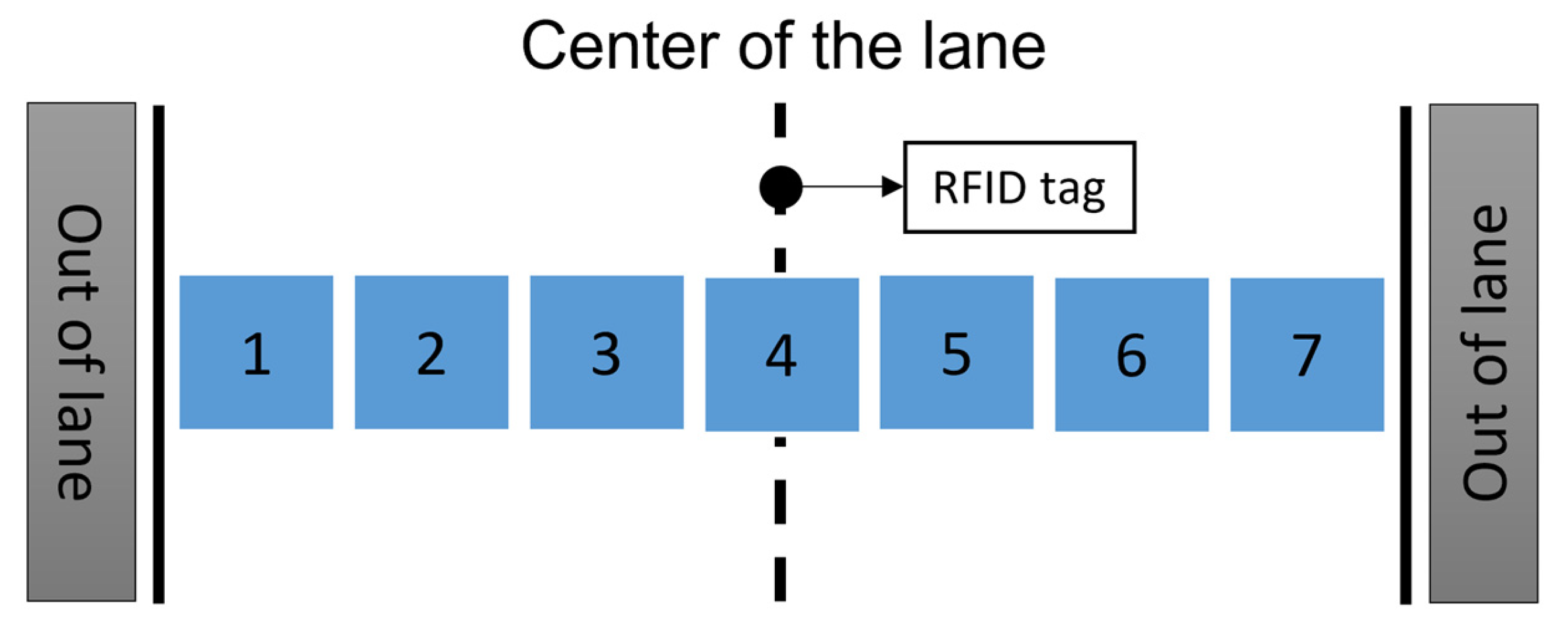
We estimate the vehicle position by applying the UHF RFID system. In this system, driving lane information is stored in the memory of the RFID tag. RFID tags are buried in the driving lane at an angle of 30°. RFID tags are set at the center of the straight driving lane, with a distance of 2 m between each tag. Four RFID antennas are placed at the front of the vehicle and are parallel to the buried RFID tags. The lateral position of the vehicle in the lane is estimated using an RFID antenna. Four antennas are attached to the vehicle at 0.4 m intervals. The antennas are numbered from 1 to 4 from left to right; the communication range of the RFID system is 0.85 m on the paved road (Figure 1). To estimate the lateral vehicle position on the driving lane, we divided the lane into 7 areas (Figure 2). These 7 areas are derived from antenna numbers that read the tag (Table 1). The seven areas in Table 1 represent the median values of each section, labeled as “d”. Using these d values, we calculated the ideal tire angle to guide the vehicle to the center of the lane 10 m ahead in the driving lane. Since vehicle direction is crucial for navigation, we use an Inertial Navigation System (INS) to track the vehicle’s heading angle relative to the magnetic north.
All this data is sent to a laptop computer (Figure 3), which determines appropriate driving instructions and presents them on a liquid crystal display (LCD) in front of the driver’s seat via the graphical user interface (GUI). The software is developed in C# and has a file size of approximately 716 KB. No perceptible delay in computation or navigation indications was observed during operation.

3.1. Integration of RFID Tag Data with Navigation Guidance Method

The information encoded in each RFID tag is directly utilized in the vehicle’s guidance. For straight navigation on unpaved roads, digits 1–5 are employed, while for paved curves and intersections, digits 1–7 are utilized. Each RFID tag store essential details such as lane direction, road type, position, and curvature data. This allows the system to provide both localization and guidance at the point where the tag is read.

3.2. Navigation Guidance Method [2]

For each of the seven lateral positions, the ideal vehicle heading angle for forward guidance on a straight road is obtained by aiming the antenna at the RFID tag at the center of the road, 10 m from the currently read antenna position (Figure 4). During low-speed driving, the target point is set between 10 and 20 m ahead. This distance is adjusted based on vehicle speed. At higher speeds, the target point can be placed further ahead. The ideal vehicle heading angle can be calculated as follows:
θ d = tan 1 d 10 ,
where d denotes the distance between the center of the driving lane and the current vehicle position.
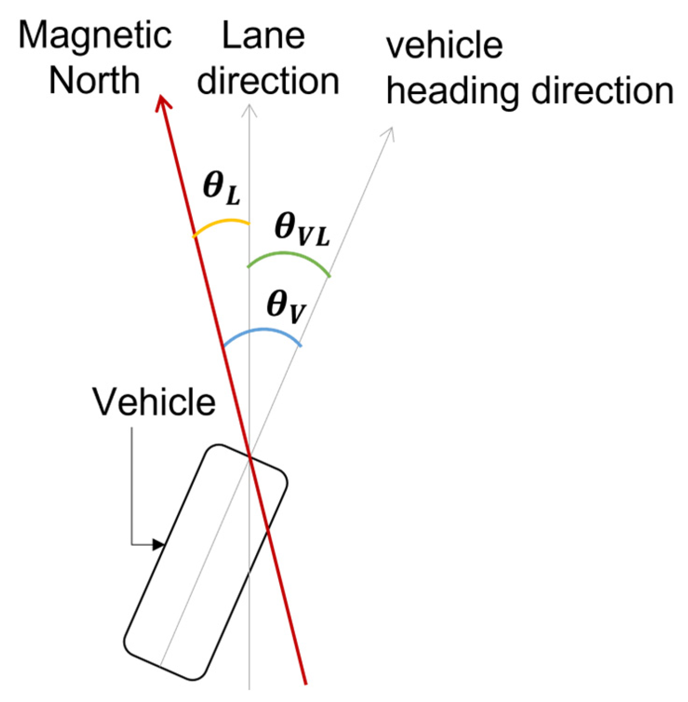
The deviation angle between the lane direction and vehicle heading angle is corrected by itself, θ V L (Figure 5). θ V L is the relative vehicle heading angle, θ V is the vehicle heading angle from magnetic north, and θ L is the lane direction from magnetic north for the RFID tag (Table 2).
θ V L = θ V θ L .
If the current vehicle position is not at the center of the driving lane and the relative vehicle heading angle θ V L is not 0, the system calculates an ideal front tire angle δ s .
δ s = θ d + k θ V L ,
where k denotes the weight coefficient.
The information encoded in each RFID tag (Table 2) provides the parameters required for vehicle guidance. The lane direction stored in digits 1–2 establishes the reference orientation of the lane ( θ L ), which is compared with the vehicle’s heading to obtain the direction correction angle θ V L (Equation (2)). The horizontal position in digit 5 defines the lane centerline, enabling calculation of the position correction angle θ d from the vehicle’s lateral position (Figure 2). These two correction terms are combined to determine the steering command δ s , which aligns the vehicle with both the center of the lane and its correct orientation (Equation (3)).

3.3. GUI

The GUI displays driving instructions on an LCD located in front of the driver [2]. These instructions are based on the lateral position and heading angle of the vehicle, as well as the front tire angle and direction of the driving lane on the straight lane. The GUI components (Figure 6) can be described as follows: the numbers correspond to those indicated in the figure.
  • The two black rectangles show front wheels. The direction of the front wheels is displayed with respect to the movement of the vehicle. The tire angle is calculated using the steering wheel angle. The relationship between the steering wheel angle and front tire angle is measured in advance. This is linked to the steering wheel, which controls the front wheels and indicates the extent to which they rotate, thereby reflecting the degree to which the steering wheel turns.
  • The green arrowhead indicates the relative direction and the lateral vehicle position in the lane. The arrowhead rotates when the direction of the vehicle changes.
  • Red text displays the information about the road on which the vehicle is currently traveling.
  • The blue bar shows the current speed of the vehicle.
  • The number at the top of the display indicates the current speed, whereas the number at the bottom represents the speed limit.
  • This value is the difference between the actual and optimal steering wheel angles.
  • The orange arrow indicates the difference between the angles on the steering wheel given on item 6. To correct the vehicle’s direction, the driver should adjust the steering until the red triangle aligns with the orange arrow.
  • The small red triangle on the steering wheel represents its current position. This virtual steering wheel is linked to actual vehicle steering via the multi-rotate potentiometer on the steering wheel shaft.

3.4. Fixing RFID Tags on the Road

To install RFID tags on a paved road, we used stick-type RFID tags designed to communicate along the vertical axis. We bury RFID tags at an angle of 30° from the road surface to optimize signal transmission and reception [1]. The installation process involves drilling a 30-degree-angled hole in the road and inserting an RFID tag. After confirming the appropriate operation of the tag, the hole is sealed with silicon sealant. Although this method is effective on paved roads, implementing the same approach on unpaved roads is challenging. Unpaved surfaces are less stable and more prone to shifting because of weather and erosion. These surface instabilities can cause the misalignment or displacement of buried RFID tags, thereby reducing communication reliability. These issues can be mitigated using geocells.

4. Proposed Methodology

4.1. Geocells

Unpaved roads often suffer from instability owing to weather conditions, such as heavy rainfall or running water, which can cause erosion, washouts, and uneven surfaces. This instability renders it challenging to maintain RFID tags at their designated positions and the necessary attitude for reliable communication with our system. A geocell, composed of high-density polyethylene (HDPE), is a type of cellular confinement system known for its high tensile strength, flexibility, and resistance to wear and environmental degradation. This makes the geocell ideal for applications where durability and longevity are essential, particularly under outdoor and variable weather conditions. The design of the geocell is inspired by natural honeycombs, where the structure becomes flexible and durable after expansion.
Depending on the application, geocells may be filled with soil, gravel, sand, or concrete to enhance stability and strength [5]. In addition to providing stability, the honeycomb structure is flexible for accommodating different terrain types and soil conditions. Geocells are suitable for road construction, erosion control, and slope stabilization. In this study, the dimensions of a cell in the geocell are 1.0 × 10⁻¹ m in height, 5.3 × 10⁻¹ m in width, and 5.8 × 10⁻¹ m in length (Figure 7). Although varying heights are available, the 1.0 × 10⁻¹ m version was selected for its cost-effectiveness.

Fillers

In this study, two types of crushed stones were used as filler materials to evaluate the communication range of the RFID system: crushed stone No. 5 and crushed stone C-40.
Crushed stone No. 5 is used as an aggregate for assemblers and base layers in civil engineering and building materials. The stone size ranges from 2.0 × 10⁻² m~1.3 × 10⁻² m. This filler is considered a low-density filler and is used to measure the communication range for our RFID system.
Crushed stone C-40 is primarily used as roadbed material and is also commonly applied as a filler in our region. The particle size of the raw stone is adjusted to prepare various types of crushed stones depending on the application. The stone size used in this study is 4.0 × 10⁻² m~0 m. Because it contains powdered crushed stone, the material becomes compact under pressure application. This filler is considered a high-density filler and is used to measure the communication range for our RFID system.
Although only these fillers were tested, geocells have proven effective across a variety of soil types. Different soils may require varying levels of stabilization and confinement to achieve optimal performance in unpaved road applications [5]. In such cases, system parameters, such as communication range and antenna power, should be appropriately adjusted.

4.2. Fixing RFID Tags on Geocells

We combined the stick-type RFID tag and geocell for our system. We fix the tag on the geocell using our proposed navigation system, using the RFID system. We designed RFID tag holders specifically for unpaved roads that are reinforced with geocells. Two types of holders are used depending on the filler material: crushed stone No. 5 (low-density filler) and C-40 (high-density filler).

4.2.1. Low-Density Filler (Crushed Stone No. 5)

An RFID tag holder (Figure 8) is designed using a polyvinyl chloride (PVC) pipe. PVC pipes, often used as water pipes, are inexpensive, durable, and can resist corrosion over time. The height of the tag holder is 0.1 m, and the RFID tag is placed in a diagonal pipe angled at 30°.
The tag holder is aligned with the geocell, and a protractor is used to adjust it to an angle of 30°. We secure the holder with vinyl ties and check the alignment. A bubble-wrapped RFID tag is inserted into the holder to ensure stability, and the opening is sealed with silicone to secure the tag. This design helps maintain the tag’s desired attitude and angle on unpaved roads.

4.2.2. High-Density Filler (Crushed Stone C-40)

The communication range may decrease in high-density filler materials. Therefore, we assume that the amount of air is low, which may result in a narrow communication range. To solve this problem, we fabricated an RFID tag holder cover (Figure 9) using a PVC pipe with a diameter of 4.0 × 10⁻² m. This cover is attached to the RFID tag holder as described in Section 4.2.1. This cover aids in creating a layer of air around the RFID tag, thereby expanding the communication range.
We attached a cover to the holder before installing the RFID tags. Following the procedure described in Section 4.2.1, the holder is aligned and adjusted to an angle of 30° and securely fastened using vinyl ties. Subsequently, we insert the RFID tag and seal the opening with silicone to maintain it securely in place (Figure 9).

4.3. Communication Range

Knowing the communication range between the RFID tag and antenna is essential to establishing the vehicle navigation system. Communication range refers to the area on the road surface where the tag and antenna can communicate. The maximum distance is measured from the burial point of the RFID tag parallel to an antenna positioned at a height of 0.4 m.
Various factors influence the communication range. The power output of the RFID device significantly affects the communication range, and a higher power output can extend the range in which the antenna can communicate with the tags. The surrounding environment, such as the soil composition and the presence of other materials, can also affect the communication range. The placement and configuration of RFID antennas can be optimized for maximum efficiency based on the communication range.

4.3.1. Measuring the Communication Range

In our navigation system, the vehicle position is determined using an RFID antenna reading tag. The accuracy of the position estimation depends on the RFID communication range. We use a plywood board arranged in a grid pattern (Figure 10) to measure this range in natural soil or on a geocell. The RFID antenna mounted at a height of 0.4 m is moved from the outer edge toward the RFID tag along the grid lines. The distance is recorded if communication is successful. Two individuals obtained the measurements, four times per grid line. The average of these readings is used to determine the communication range of each grid line.

4.3.2. Communication Range on Paved Roads

The communication range on a paved road has been measured in [2]. The maximum horizontal and vertical lengths of the communication range were 8.56 × 10⁻¹ m and 9.3 × 10⁻¹ m, respectively. Because the lateral communication range is important for vehicle location estimation, the ideal circle of the communication range is set to 8.5 × 10⁻¹ m in diameter (Figure 11).

4.3.3. Communication Range on Unpaved Roads

Several experiments were conducted to measure the communication range on an unpaved road by changing the antenna output and filler material. An excessively wide communication range may hinder the vehicle from navigating to the center of the driving lane. Conversely, a narrow communication range may result in gaps between adjacent antennas, preventing them from reading the RFID tags. In other words, the measurement of the communication range determines the driving conditions [1].
Communication range of crushed stone No. 5. We dug a 0.1 m deep square with dimensions of 2 m. The geocell grid and RFID tag holder are buried at the center of the hole and filled with crushed stone No. 5. The communication range of crushed stone No. 5 was measured on two separate days using the method outlined in Section 4.3.1; Table 3 summarizes the results. In Case 1 (Figure 12), with an antenna output of 24 dBm, the width of the measured communication range is 9.37 × 10⁻¹ m. Because this exceeded our ideal target range, we reduced the antenna output in the second trial. In Case 2 (Figure 13), with the antenna output reduced to 22 dBm, the measured communication range is 7.99 × 10⁻¹ m. This value is close to the ideal range for unpaved roads. Consequently, we adopted a communication range diameter of 8.0 × 10⁻¹ m for crushed stone No. 5.
Communication range of crushed stone C-40. We create a 10 m long and 4 m wide geocell road (Figure 14). The geocell grid is spread over the entire surface, and four RFID tag holders are buried at approximately 2 m intervals in the center of the lane. C-40 crushed stone is used as the filler.
We observed that the communication range is narrower than previously recorded, with a diameter of 6.99 × 10⁻¹ m and an antenna output of 30 dBm. This can be attributed to the difference in filler materials. The crushed stone C-40 used has more fine particles than crushed stone No. 5. Therefore, the amount of air between the filler (crushed stone C-40) is smaller than that observed in the case of crushed stone No. 5, resulting in a narrower communication range. This problem can be solved by using the RFID tag holder (Section 4.2.2.). We measured the communication range in this area three times (Table 4). In Case 1, the communication range is 1.159 m wide with an antenna output of 30 dBm (Figure 15), which is larger than the ideal communication range. This is because the antenna output was at its maximum. Therefore, we decreased the antenna output to 26 dBm. We obtained the measurements of Case 2 under wet and icy road conditions in December (Figure 16). In this case, the communication range is 8.05 × 10⁻¹ m with an antenna output of 26 dBm. Case 3 measurements were obtained under a dry road in June (Figure 17), wherein the communication range is 9.0 × 10⁻¹ m in width with an antenna output of 26 dBm.
Although the antenna output is 26 dBm in Cases 2 and 3, the road conditions affected the communication range. In Case 2, the soil was wet and parts of the geocells were filled with ice and snow. In Case 3, the soil was dry, and the filler thinned due to snowmelt. We examined the average distance from the center of the driving lane for positions 1–7. For each position, the distance from the lane center is shown in Table 5, where distances to the right are positive and those to the left are negative. We selected the communication range of 8.5 × 10⁻¹ m as it represents a balanced midpoint between 8.0 × 10⁻¹ and 9.0 × 10⁻¹ m with an antenna output of 26 dBm.

5. Experimental Field

The experiment was conducted in a field 4 m wide and 50 m long, which was specifically constructed for this study at the test site (Figure 18). A geocell was installed on the natural soil as part of the road’s foundation. Along the center of the lane, we installed 23 RFID tags spaced at approximately 2 m intervals. As indicated in Figure 19, the road begins at row number 5 as the starting point and ends at row number F. The direction of the lane from the starting point to the destination is oriented 176° from magnetic north.
Because the geocell system is made from HDPE and filled with C-40 crushed stone, the shape of each cell varies, rendering it challenging to place the tags accurately at 2 m intervals along the centerline. Consequently, we measured the actual distances between adjacent tags along with their deviations from the center of the lane. These measurements (Figure 18) are obtained in meters, where “R” and “L” indicate the distances to the right and left, respectively, relative to the travel direction.
Table 6 summarizes the deviation of RFID tags in the geocell lane. The maximum standard deviation observed is 5.8 × 10⁻² m to the right. This small value indicates that the tag deviations are relatively consistent and show little fluctuation. Likewise, the 95% confidence intervals (CIs) derived from the sample data are narrow and remain entirely above zero. Together, the low standard deviations and tight CI suggest that tag placement is stable, and any deviations are minor and unlikely to compromise the navigation system’s ability to maintain its intended lane position.

6. Driving Experiment

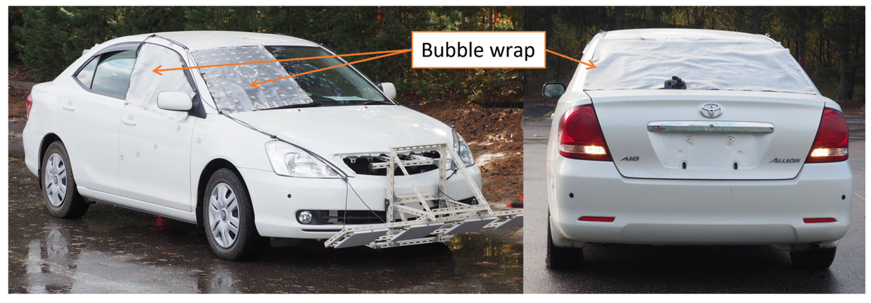
The vehicle navigation system is installed in the experimental vehicle, and several driving tests are conducted. To simulate low-visibility conditions, a bubble wrap combined with a black vinyl sheet is placed on the windshield, and additional bubble wrap is applied to the sides of the driver’s seat and rear window (Figure 20).
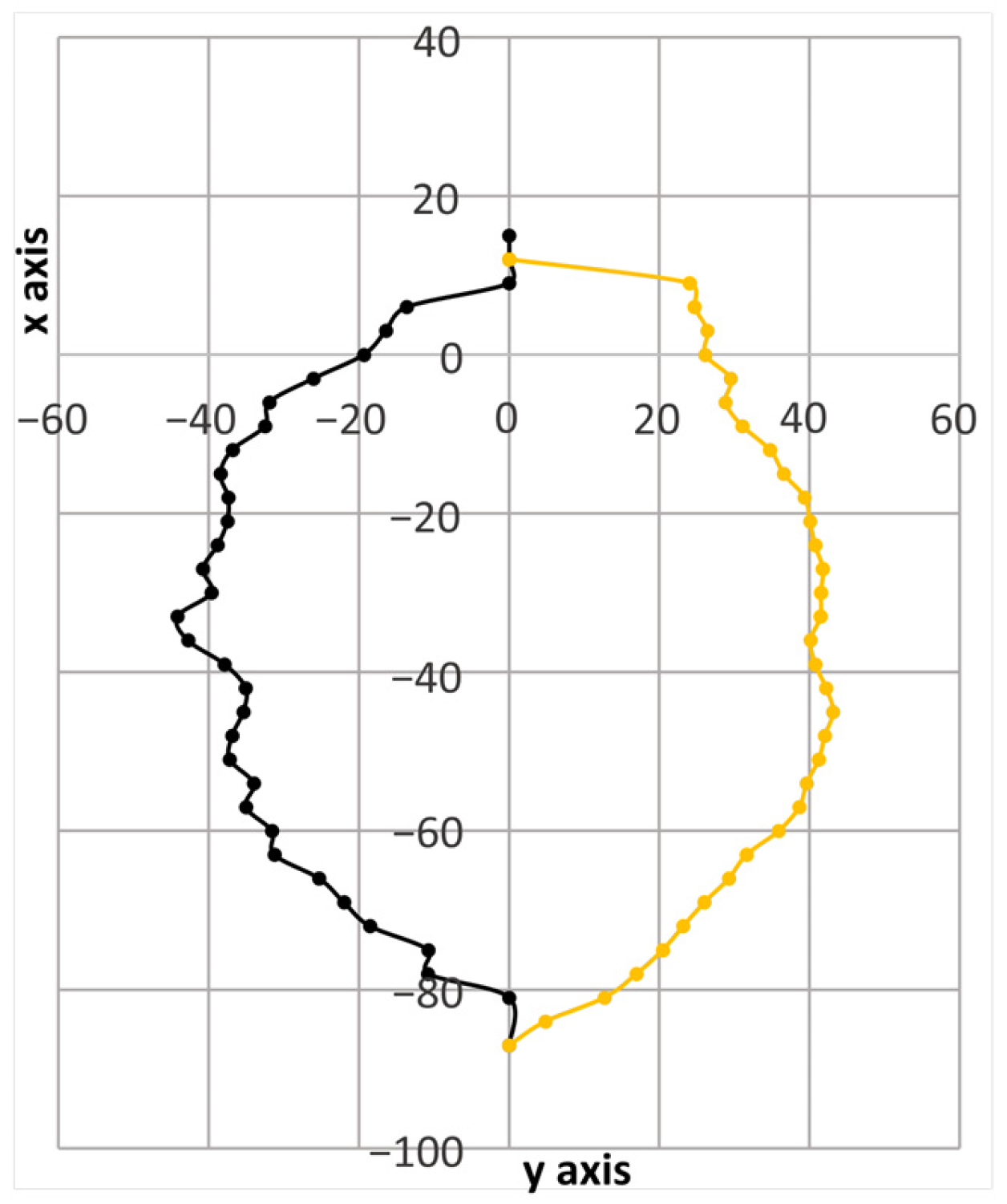
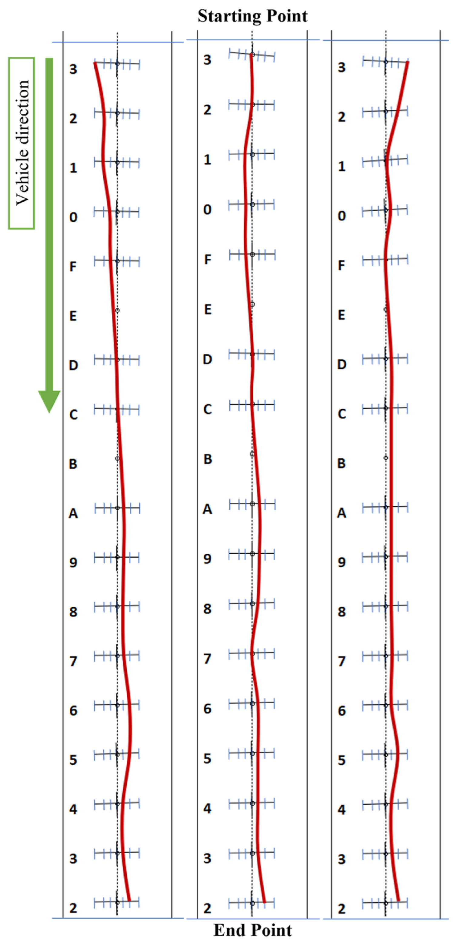
We conducted multiple tests on an unpaved road, starting from the center, left, and right sides of the lane. The accuracy is assessed at the final position (Figure 21). INS continuously calculated the vehicle’s magnetic direction and occasionally provided unstable readings that differed from the actual direction. This implied that the vehicle did not stay in the center of the lane. The trial navigation results shown in Figure 21 present an average deviation of 2.2 × 10⁻¹ m and a standard deviation of 3.0 × 10⁻¹ m.

6.1. Vehicle Heading Angle Correction Method

We updated the previous INS correction method because it occasionally became unstable and provided inaccurate values for the vehicle’s lane direction. The new correction method is based on the RFID tag reading history and offers more accurate and stable results.
We used a different formula to obtain the vehicle correction angle θ V L . We considered d N as the position at which the current RFID tag P N is read, d L as the last position detected by the system where the last-read RFID tag P L is located (Figure 22), and d i s t P N P L as the distance between RFID tags P N   a n d   P L . The vehicle correction angle was calculated using the following equations:
R F I D d i r = θ L tan 1 d N d L d i s t P N P L ,
θ V L = θ L R F I D d i r ,
where d N indicates the current position of the vehicle and d L refers to the last position detected by the system.
For a smoother vehicle movement, we apply a weighting factor of 0.2 to the vehicle heading angle.

6.2. Driving Experiment Performed Using the New Vehicle Heading Angle Correction Method

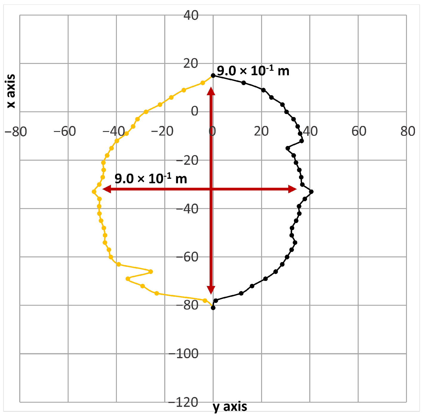
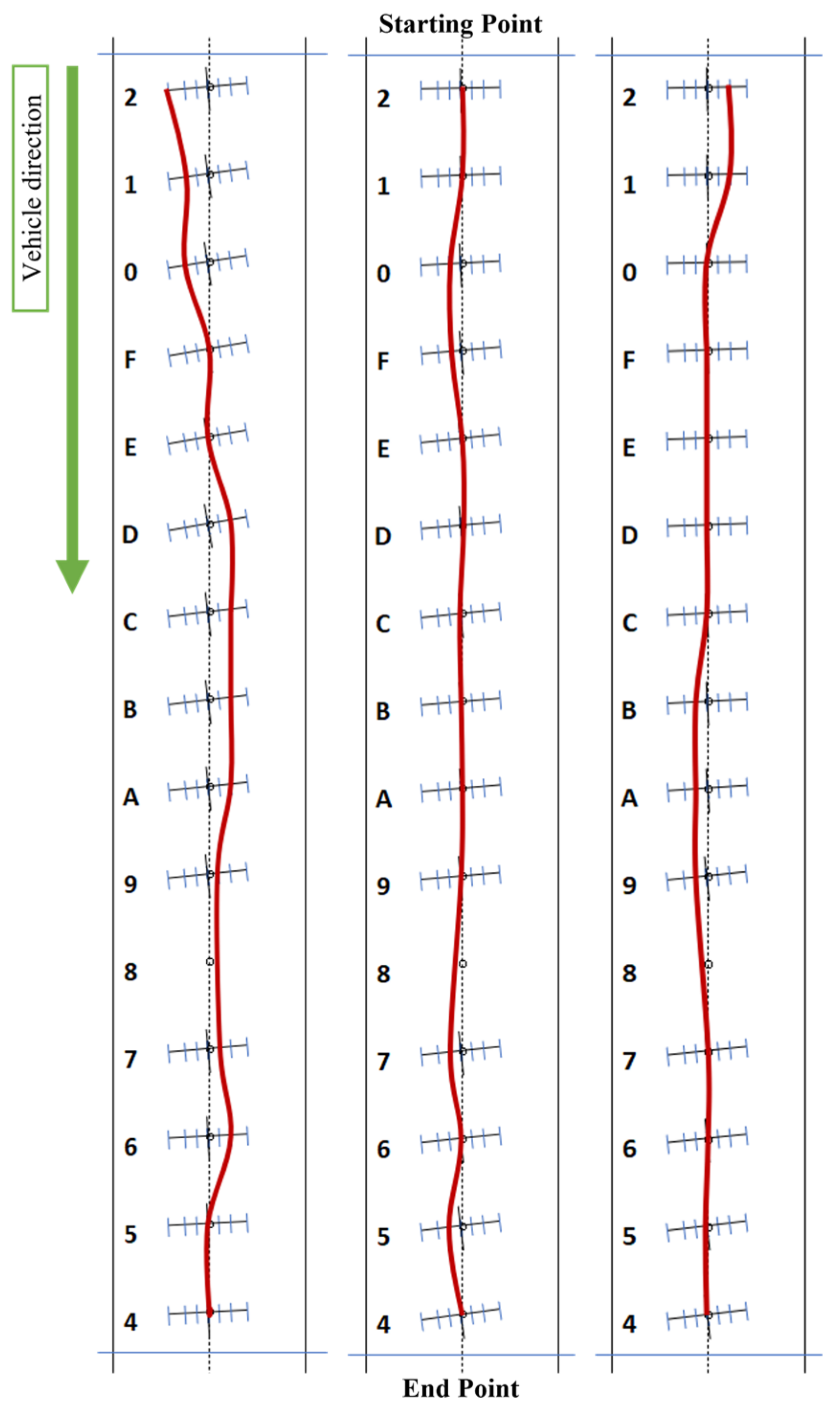
We conducted driving experiments using the new navigation method, beginning at the center, left side, and right side of the lane (Figure 23). Here, the vehicle successfully maintained its position near the center of the lane. The trial navigation results shown in Figure 23 present an average deviation of 1.37 × 10⁻¹ m to the left of the center and a standard deviation of 9.8 × 10⁻² m, indicating an improvement in the vehicle navigation performance.
Table 7 summarizes the results of the navigation trials conducted between August to January. Before applying the vehicle heading angle correction method, we performed 31 trials during which there was a one-lane departure incident. The deviation from the center of the vehicle to the center of the driving lane is measured manually. The minimum, maximum, standard deviation, and average deviation values are then calculated. We performed the same analysis on 102 trials conducted after implementing the heading angle correction method using RFID tag reading history. Because the deviation was well within the center of the lane range, the vehicle continued to maintain its position at the center of the lane despite the slight misalignment in the RFID tag (Section 5). These trials were carried out under various weather conditions, including harsh winter tests with active snowfall and up to 0.23 m of snow and ice covering the road. Even in these extreme conditions, the short communication distance between the tag and antenna ensured robust detection and stable communication.
We conducted a comparative analysis between the current study on unpaved roads and the findings of Morita et al. (2021) [2] on paved roads. Both systems successfully navigated the vehicle to the center of the lane. Since the CI is narrow and close to the standard deviation, it means that even though the data points vary somewhat, the average value can still be estimated with good accuracy and reliability.
During the driving experiment on the unpaved road, INS was disturbed and showed an incorrect vehicle heading angle. Therefore, we made a new compensation method to correct INS errors by using the history of RFID tag readings. On paved roads, RFID tags are securely buried at 2-m intervals along the center of the driving lane, ensuring they remain stationary and unaffected by external factors [2]. However, on unpaved roads, the RFID tags may deviate slightly from the in-tended lane center, as illustrated in Figure 18. Despite the RFID tag placement error, the results of the running experiment were satisfactory.

7. Conclusions

Previous studies have demonstrated the potential of using RFID tags for vehicle navigation, particularly on paved roads. However, applying similar technologies to unpaved roads introduces a set of challenges. These roads are often subject to extreme weather conditions and uneven surfaces, which can dislodge or misalign the RFID tags. Such instability can compromise the reliability of a navigation system.
To address these challenges, in this study, we propose a navigation system that integrates UHF RFID technology with geocell-based ground reinforcement. Geocells, commonly used in civil engineering for soil stabilization, were employed to protect and maintain the placement of RFID tags in harsh road environments. Additionally, we designed RFID tag holders and protective covers to further stabilize the RFID tag’s communication range. Together, these components ensured that the navigation system remained functional on unpaved roads with C-40 filler. We measured the RFID tag communication range based on antenna output power and road filler characteristics. Furthermore, we implemented a new INS correction method, which utilizes RFID tag reading history to estimate heading direction and compensate for magnetic disturbances. Despite minor misalignments in the RFID tags, the system remained robust, enabling the vehicle to reliably maintain its trajectory within the center of the lane. Our navigation trials confirmed that the system was capable of keeping the vehicle reliably centered within its lane under various environmental conditions. This robustness, despite the inherent unpredictability of unpaved terrain, highlights the system’s practical viability for real-world applications in mountainous or forested areas where GPS signals are weakened by obstacles such as trees, branches, and leaves.
In conclusion, the proposed navigation system demonstrates a meaningful advancement in RFID-based localization for unpaved roads. While the current study focused on straight roads, future research should expand its scope to include curved roads, intersections, and inclines. For such scenarios, our system can utilize Ackermann steering geometry [25], calculating the appropriate steering angles using tangent line direction and curve radius information stored in the RFID tags. This extension aims to broaden the applicability of RFID-based navigation to more complex unpaved environments, building on prior work conducted primarily on paved roads.
Our system is developed on paved and unpaved roads for simplicity and robustness. Rather than competing with modern systems, this study aims to provide a complementary solution where GPS accuracy is unreliable, such as in mountainous terrain and dense forests. Thus, we hope that our research can complement advanced connected vehicle environments [26] and multi-agent traffic coordination frameworks [27], particularly in snowy and cold regions.

Author Contributions

The authors are identified by the following abbreviations: G.M.C.G., T.K. (Takayuki Kawaguchi), D.N., K.K. and T.K. (Takeshi Kawamura). Conceptualization, T.K. (Takeshi Kawamura); Data curation, G.M.C.G.; Formal analysis, G.M.C.G. and T.K. (Takeshi Kawamura); Investigation, G.M.C.G. and T.K. (Takeshi Kawamura); Methodology, T.K. (Takeshi Kawamura); Project administration, T.K. (Takeshi Kawamura); Resources, T.K. (Takayuki Kawaguchi), D.N., K.K. and T.K. (Takeshi Kawamura); Software, G.M.C.G.; Supervision, T.K. (Takeshi Kawamura); Validation, G.M.C.G. and T.K. (Takeshi Kawamura); Visualization, G.M.C.G. and T.K. (Takeshi Kawamura); Writing—original draft preparation, G.M.C.G. and T.K. (Takeshi Kawamura); Writing—review and editing, G.M.C.G. and T.K. (Takeshi Kawamura). All authors have read and agreed to the published version of the manuscript.

Funding

The authors declare no relevant financial or non-financial interests to disclose.

Institutional Review Board Statement

Not applicable.

Informed Consent Statement

Not applicable.

Data Availability Statement

All data and materials related to this study are available upon request.

Acknowledgments

This research was supported by the Research Center for Okhotsk Agriculture, Forestry, and Fisheries Engineering Collaboration (CAFFE).

Conflicts of Interest

The authors declare no conflicts of interest.

Abbreviations

The following abbreviations are used in this manuscript:
GPSGlobal Positioning System
RFIDRadio Frequency Identification
RFRadio Frequency
LiDARLight Detection and Ranging
SLAMSimultaneous Localization and Mapping
UHFUltrahigh Frequency
INSInertial Navigation System
LCDLiquid Crystal Display
GUIGraphical User Interface
HDPEHigh-Density Polyethylene
PVCPolyvinyl Chloride
CIsConfidence Interval

References

  1. Kawamura, T.; Kashiwa, T.; Taguchi, K. Vehicle navigation system using UHF RF-ID. Eur. Transp. Res. Rev. 2013, 5, 91–99. [Google Scholar] [CrossRef]
  2. Morita, R.; Kawamura, T. Vehicle navigation using UHF RFID system under low visible condition caused by heavy snowfall—Development of four antenna system. In Proceedings of the 2021 International Workshop on Modern Science and Technology, Kitami, Japan, 29 September 2021; pp. 51–56. [Google Scholar]
  3. Hokkaido Prefectural Government. Available online: https://www.pref.hokkaido.lg.jp/ss/tuk/920hsy/114632.html (accessed on 10 July 2024).
  4. Book Baker. Available online: https://www.bookbaker.com/tr/v/Geocell-A-Comprehensive-Guide-for-Construction-Introduction-to-Geocell-Technology/8a5ad138-3de6-469b-bf52-0c03fe0721d7/1 (accessed on 15 November 2023).
  5. Martins, C.; Macedo, J.; Pinho-Lopes, M. Geocells for Unpaved Roads: Analysis of Design Methods from the Literature. Int. J. Geosynth. Ground Eng. 2024, 10, 57. [Google Scholar] [CrossRef]
  6. Yamaha Motor Co., Ltd. Available online: https://www.yamaha-motor.co.jp/gsm/ (accessed on 20 June 2024).
  7. Omae, M.; Hirano, S.; Kamisaka, T. Study on Measurement of Lateral Displacement for Vehicles Traveling on Road with Electromagnetic Guidance. J. Soc. Automot. Eng. Jpn. 2022, 53, 591–597. [Google Scholar]
  8. Ando, T.; Mukumoto, H.; Aoki, K.; Okazaki, S.; Nagao, T.; Aoyama, H.; Yamamoto, M.; Nakano, K. Localization using global magnetic positioning system for automated driving bus and intervals for magnetic markers. IEEE Trans. Intell. Veh. 2022, 8, 878–887. [Google Scholar] [CrossRef]
  9. Ishii, K.; Shimono, K.; Suda, Y.; Ando, T.; Nagao, T.; Yamamoto, M.; Segawa, M. Vehicle localization using magnetic markers incorporating EKF and maximum likelihood estimation. IFAC-PapersOnLine 2022, 55, 202–207. [Google Scholar] [CrossRef]
  10. Chen, R.; Huang, X.; Zhou, Y.; Hui, Y.; Cheng, N. UHF-RFID-Based Real-Time Vehicle Localization in GPS-Less environments. IEEE Trans. Intell. Transp. Syst. 2021, 23, 9286–9293. [Google Scholar] [CrossRef]
  11. Wang, J.; Ni, D.; Li, K. RFID-Based Vehicle Positioning and Its Applications in Connected Vehicles. Sensors 2014, 14, 4225–4238. [Google Scholar] [CrossRef] [PubMed]
  12. Chon, H.; Jun, S.; Jung, H.; An, S. Using RFID for Accurate Positioning. J. Glob. Position. Syst. 2004, 3, 32–39. [Google Scholar] [CrossRef]
  13. Das, P.; Agrawal, D.P. RFID for indoor position determination. In Smart Innovation, Systems and Technologies; Springer Nature: London, UK, 2014; pp. 561–567. [Google Scholar] [CrossRef]
  14. D’Mello, S.; Mathews, E.; McCauley, L.; Markham, J. Impact of position and orientation of RFID tags on real time asset tracking in a supply chain. J. Theor. Appl. Electron. Commer. Res. 2008, 3, 1–12. [Google Scholar] [CrossRef]
  15. Wang, Z.M.; He, B.Q. RFID Location Algorithm. MATEC Web Conf. 2016, 63, 05007. [Google Scholar] [CrossRef]
  16. Ajroud, C.; Hattay, J.; Machhout, M. A novel holographic technique for RFID localization in indoor environments. Multimed. Tools Appl. 2023, 83, 29827–29840. [Google Scholar] [CrossRef]
  17. Charléty, A.; Breton, M.L.; Larose, E.; Baillet, L. 2D Phase-Based RFID Localization for On-Site Landslide Monitoring. Remote Sens. 2022, 14, 3577. [Google Scholar] [CrossRef]
  18. Ting, S.; Kwok, S.; Tsang, A.H.; Ho, G.T. The study on using passive RFID tags for indoor positioning. Int. J. Eng. Bus. Manag. 2011, 3, 8. [Google Scholar] [CrossRef]
  19. Motroni, A.; Buffi, A.; Nepa, P. A survey on indoor vehicle localization through RFID technology. IEEE Access 2021, 9, 17921–17942. [Google Scholar] [CrossRef]
  20. Shen, E.; Duan, S.; Guo, S.; Yang, W. Object localization and sensing in Non-Line-of-Sight using RFID tag matrices. Electronics 2024, 13, 341. [Google Scholar] [CrossRef]
  21. Laconte, J.; Kasmi, A.; Aufrère, R.; Vaidis, M.; Chapuis, R. A survey of localization methods for autonomous vehicles in highway scenarios. Sensors 2021, 22, 247. [Google Scholar] [CrossRef] [PubMed]
  22. Kamijo, S.; Gu, Y.; Hsu, L. Autonomous Vehicle Technologies: Localization and Mapping. IEICE ESS Fundam. Rev. 2015, 9, 131–141. [Google Scholar] [CrossRef]
  23. Levinson, J.; Thrun, S. Robust vehicle localization in urban environments using probabilistic maps. In Proceedings of the 2010 IEEE International Conference on Robotics and Automation, Anchorage, AK, USA, 15 July 2010; pp. 4372–4378. [Google Scholar] [CrossRef]
  24. Cheng, J.; Zhang, L.; Chen, Q.; Hu, X.; Cai, J. A review of visual SLAM methods for autonomous driving vehicles. Eng. Appl. Artif. Intell. 2022, 114, 104992. [Google Scholar] [CrossRef]
  25. Norris, W. Steering. In Modern Steam Road Wagons; Longmans, Green and Co.: London, UK, 1906; pp. 63–67. [Google Scholar]
  26. Lu, Y.; Wang, W.; Bai, R.; Zhou, S.; Garg, L.; Bashir, A.K.; Jiang, W.; Hu, X. Hyper-relational interaction modeling in multi-modal trajectory prediction for intelligent connected vehicles in smart cities. Inf. Fusion 2024, 114, 102682. [Google Scholar] [CrossRef]
  27. Ullah, I.; Singh, S.K.; Adhikari, D.; Khan, H.; Jiang, W.; Bai, X. Multi-Agent Reinforcement Learning for task allocation in the Internet of Vehicles: Exploring benefits and paving the future. Swarm Evol. Comput. 2025, 94, 101878. [Google Scholar] [CrossRef]
Figure 1. RFID antenna frame measurements and communication range of the system with 0.85 m diameter [2].
Futuretransp 05 00143 g001
Figure 2. Top view of the vehicle position on the driving lane [2].
Futuretransp 05 00143 g002
Figure 3. Sideview of the Vehicle guidance system.
Futuretransp 05 00143 g003
Figure 4. Ideal vehicle heading angle for a straight lane.
Futuretransp 05 00143 g004
Figure 5. Relative vehicle heading angle θ V L .
Futuretransp 05 00143 g005
Figure 6. GUI of the proposed vehicle navigation system.
Futuretransp 05 00143 g006
Figure 7. Geocell grid.
Futuretransp 05 00143 g007
Figure 8. Side and front views of the RFID tag holder.
Futuretransp 05 00143 g008
Figure 9. (a) Tag holder with cover attached to a geocell. (b) Tag holder with cover buried in test area.
Futuretransp 05 00143 g009
Figure 10. RFID antenna on a gridded plywood board.
Futuretransp 05 00143 g010
Figure 11. Communication range on a paved road.
Futuretransp 05 00143 g011
Figure 12. Communication range in Case 1.
Futuretransp 05 00143 g012
Figure 13. Communication range in Case 2.
Futuretransp 05 00143 g013
Figure 14. 10 m long geocell lane used for measuring the communication range.
Futuretransp 05 00143 g014
Figure 15. Communication range for Case 1.
Futuretransp 05 00143 g015
Figure 16. Communication range for Case 2.
Futuretransp 05 00143 g016
Figure 17. Communication range for Case 3.
Futuretransp 05 00143 g017
Figure 18. Experimental straight lane with white bags placed as a reference for RFID tag burial.
Futuretransp 05 00143 g018
Figure 19. Layout of the experimental straight lane built with geocell, indicating RFID tag locations and deviations. Orange dots represent buried RFID tags.
Futuretransp 05 00143 g019
Figure 20. Side and back views of the experimental vehicle with bubble wrap.
Futuretransp 05 00143 g020
Figure 21. The red lines represent the vehicle trajectory with respect to the starting point from the center, left side, and right sides of the lane.
Futuretransp 05 00143 g021
Figure 22. New vehicle heading angle correction method.
Futuretransp 05 00143 g022
Figure 23. The red lines represent the vehicle trajectory with respect to the starting point from the center, left side, and right side of the lane.
Futuretransp 05 00143 g023
Table 1. Reading antenna number and the estimated position of the vehicle with a communication range of 0.85 m [2].
PositionReading AntennasEstimated Distance d [m] Between the RFID Tag and the Vehicle Center
1Only Antenna 4+0.7125
2Antenna 3 and Antenna 4+0.4125
3Only Antenna 3+0.2
4Antenna 3 and Antenna 20
5Only Antenna 2−0.2
6Antenna 2 and Antenna 1−0.4125
7Only Antenna 1−0.7125
Table 2. Tag information relating to navigation guidance equations; all the information stored in the tag is in hexadecimal.
Tag DigitType of InformationStored Information
1 Lane   direction   θ L , Tangent Line directionLane direction relative to magnetic north. On paved curved roads and intersection it is the tangent line direction.
2
3Road TypeStraight Line: 0, 30 m before intersection: 1, Intersection: 3,
Right curve: 4, Left curve: 5, 30 m before curves: 6, 7
4Sequence numberSequential identifier of the tag
(Repeat from 0 to F recursively)
5Horizontal positionLateral placement of the tag (1, 2, 3)
(For a 4-antenna system [2] we use 2 for the lane center in this study)
6Turning radiusRadius of curvature for curves and intersections
7
Table 3. Communication range of crushed stone No. 5.
FillerAntenna Output [dBm]Comm. Range (Ø) [m]
1Crushed stone No. 5249.37 × 10−1
2data227.99 × 10−1
Table 4. Communication range of crushed stone C-40 with the RFID tag holder cover.
CaseFillerAntenna Output [dBm]Comm. Range (Ø) [m]
1Crushed stone C-40301.159
2268.05 × 10−1
3269.0 × 10−1
Table 5. Comparison between the vehicle lateral position distance from the lane center for positions 1–7 for the communication range diameters of 8.0 × 10⁻¹, 8.5 × 10⁻¹, and 9.0 × 10⁻¹ m.
PositionDiameter of Communication Range [m]
8.0 × 10−18.5 × 10−19.0 × 10⁻¹
1+0.7+0.7125+0.725
2+0.4+0.4125+0.425
3+0.2+0.2+0.2
4000
5−0.2−0.2−0.2
6−0.4−0.4125−0.425
7−0.7−0.7125−0.725
Table 6. The maximum, minimum, standard deviation, average absolute deviation, and CI of positioning errors were calculated in meters with respect to the RFID tag locations on the geocell.
RFID Tag Deviation [m]
Left SideRight SideEntire Lane
Maximum4.3 × 10−25.8 × 10−25.8 × 10−2
Minimum8.0 × 10−33.0 × 10⁻³⁰
Standard deviation1.45 × 10−21.83 × 10−21.74 × 10−2
Average2.84 × 10−21.92 × 10−22.15 × 10−2
95% CI [1.98 × 10⁻², 3.697 × 10⁻²] [7.86 × 10⁻³, 3.05 × 10⁻²] [1.43 × 10⁻², 2.86 × 10⁻²]
Table 7. Total number of vehicle navigation trials and results for paved and unpaved roads. Unpaved road trials were conducted between August and January.
Unpaved RoadPaved Road
Vehicle Heading Angle Correction MethodNo Vehicle Heading
Angle Correction [2]
BeforeAfter
Total Trails31102126
Lane out incident100
Minimum deviation [m]002.5 × 10⁻²
Maximum deviation [m]5.4 × 10−11.5 × 10−12.5 × 10⁻¹
Standard deviation [m]1.59 × 10−13.73 × 10−21.55 × 10⁻¹
Average deviation [m]1.376 × 10−14.46 × 10−25.46 × 10⁻²
95% CI [m] [8.16 × 10⁻², 1.93 × 10⁻¹] [3.73 × 10⁻², 5.18 × 10⁻²] [2.75 × 10⁻², 8.16 × 10⁻²]
Disclaimer/Publisher’s Note: The statements, opinions and data contained in all publications are solely those of the individual author(s) and contributor(s) and not of MDPI and/or the editor(s). MDPI and/or the editor(s) disclaim responsibility for any injury to people or property resulting from any ideas, methods, instructions or products referred to in the content.