Article

Evaluation of Lithium-Ion Battery Performance under Variable Climatic Conditions: Influence on the Driving Range of Electric Vehicles

by
Carlos Armenta-Déu
1,* and
Benjamin Boucheix
2
1
Department of Matter Structure, Thermal Physics and Electronics, Faculty of Physical Sciences, Complutense University of Madrid, 28040 Madrid, Spain
2
Campus Universitaire des Cézeaux, Polytechnical Institute, Université Clermont Auvergne, 2 Avenue Blaise-Pascal, TSA 60206-CS 60026, CEDEX, 63178 Aubière, France
*
Author to whom correspondence should be addressed.
Future Transp. 2023, 3(2), 535-551; https://doi.org/10.3390/futuretransp3020031
Submission received: 25 January 2023 / Revised: 13 March 2023 / Accepted: 3 April 2023 / Published: 27 April 2023

Abstract

:
The goal of this paper is the evaluation of lithium-ion batteries that power electric vehicles (EVs) under variable climatic conditions to determine how the driving range of a vehicle is modified because of changes in battery performance caused by the variability of environmental conditions. The influence of sudden changes in ambient temperature on the performance of the battery that powers electric vehicles has been studied and analyzed. The study is focused on how trips across geographical zones with different climates affect the autonomy of an electric vehicle’s battery, and thus the driving range of the electric vehicle (EV). A model has been developed to reproduce on a laboratory scale the real conditions to which EVs are subject when circulating under fluctuating temperatures, which force the battery to operate in a transient or non-steady state. A simulation has been run for different climatic conditions to evaluate the performance of the battery and the driving range of the electric vehicle under variable operating conditions. A laboratory prototype has been designed and built to validate the modeling and to adjust the theoretical approach to experimental values through the corresponding correction factor in case significant deviations occur. The model has been validated for a simulated route that reproduces a real driving trip for specific geographical areas. The model indicates that there is a shortening in the global driving range of 43.5 km over a trip distance of 538 km, which means there is a reduction of 8%. The simulation has been applied to a specific geographical area in the nearby of the city of Lyon (France), for a temperature gap of 39 °C, from −6 °C to 33 °C, but can also be used for almost any other zones, although the reduction in driving range may vary because of specific climate conditions.

1. Introduction

It is known that any kind of battery is affected in its performance by the operating temperature [1,2,3,4,5,6]; changes in a battery behavior influence its autonomy and thus the driving range of the electric vehicle powered by the battery. The electric vehicle driving range is rated under specific driving conditions [7,8,9,10,11], which do not include temperature variations during rating tests. The general effects of temperature on the driving range of electric vehicles have been widely studied and characterized [12,13,14,15,16], and more specifically, the seasonal variation in temperature has been studied and characterized [17,18,19,20]. Nevertheless, the sudden changes in ambient temperature caused by variable climatic conditions, despite the recent advances in this field, have not yet been sufficiently studied and analyzed [21,22].
Changes in temperature affect not only the performance of the battery that powers an electric vehicle, but its capacity and autonomy. If changes are produced at a quick rate, the battery enters a transient operating mode, with the capacity of changing for every transient state; these changes in the capacity modify the depth of discharge of the battery at every state, thus modifying the global autonomy and the driving range of the electric vehicle. As a consequence, the current methods of calculation of the driving range are useless since they have been developed for the nontransient state. Transient processes require a detailed analysis of the different operating conditions at every transient state, so the discharge process of the battery should be treated as a succession of partial quasi-steady states where operating conditions can be considered constant.
The route of an electric vehicle subject to sudden and continuous changes of temperature should be treated as a succession of partial segments of driving distance, short enough to be considered as a quasi-steady state; since an electric vehicle is powered by a battery, the segmentation process must be applied to the discharge process of the battery.
Battery capacity is a parameter rated under specific operating conditions [23,24,25]. The rating process is currently run at a constant temperature that corresponds to standard discharge conditions [26,27,28]. However, if a battery is submitted to sudden changes during discharge, the variation in the capacity rate modifies the discharge rate too; in such conditions, the depth of discharge corresponding to a specific partial discharge should be recalculated using the modified value of the capacity for the new operating temperature.
At present, the majority of studies have been devoted to determining the influence of temperature on battery performance, but an analysis of how climatic conditions influence the driving range of electric vehicles because of the variation in the performance of the battery that powers an electric vehicle is missing. This study intends to analyze this effect, since the reference driving range provided by the manufacturers do not take it into consideration. We consider it important to evaluate the driving range of an electric vehicle with the highest accuracy possible because an error in the information provided by the vehicle control system to the driver may cause the vehicle to suddenly stop before arriving to the charge station.
The analysis of the real performance of the battery under variable climatic conditions implies the study of the battery’s performance for different environmental situations in a single trip; the goal is, therefore, to obtain an algorithm that can be implemented in the control unit software of the electric vehicle, so that the unit can recalculate the driving range in a dynamic way, taking into account the variations in the performance of the battery when climatic changes occur.

2. Theoretical Foundations

The capacity of a battery can be expressed as a function of temperature dependence as [29]:
C T = 1.0047 C r I D I r e f 1.0213 T r e f T D 0.4393
where Cr is the real capacity of the battery for specific discharge conditions, which do not always match standard ones, ID is the operational discharge current, Iref is the reference discharge current, TD is the temperature of the discharge process, and Tref is the temperature at the reference discharge cycle. The reference values of the current and temperature, Iref and Tref are given by the manufacturer.
The depth of discharge (DOD) of any partial process can be expressed as:
D O D i = I D , i t D , i C T , i
where subindex i indicates the order of the process, tD,i is the running time for the partial discharge process and Cr,i is the real capacity corresponding to the i-process. The real capacity depends on the nominal capacity of the battery, Cn, as in:
C r , i = C n f c , i
The capacity correction factor, fC, for lithium-ion batteries is given by [30]:
f C , i = 0.9571 t D , i 0.0148
where tD,i accounts for the discharge time of the i-process.
Combining Equations (1) to (4):
D O D i = 1.0399 C n I r e f 1.0213 T r e f 0.4393 t D , i 0.9852 I D , i 0.0213 T D , i 0.4393
Equation (5) gives the partial depth of discharge of the battery as a function of the nominal capacity of the battery, the reference values of the discharge current and temperature, and the specific operating conditions for the i-process, discharge current, interval time and operating temperature.
The discharge current can be obtained from the power requirements of the electric vehicle, Pi:
I D , i = P i V b a t , i
where Vbat represents the average battery voltage in the i-process.
For lithium-ion batteries, the battery voltage evolution follows a linear decay with the depth of discharge, given by:
V b a t , i = V b a t , o m ( D O D ) i
m is the slope of the discharge current process that can be obtained from the expression:
m = V b a t , o V b a t , o f f 100
where Vbat,o is the battery voltage at the full charge state, and Vbat,off is the cut-off voltage corresponding to the full discharge state.
It was assumed that the battery can be completely discharged down to a null state of charge (SOC), SOC = 0 or DOD = 100.
Combining Equations (6)–(8):
I D , i = P i V b a t , o V b a t , o V b a t , o f f 100 ( D O D ) i
Replacing Equation (5):
D O D i = 1.1405 C n I r e f 1.0213 T r e f 0.4393 P i 0.0213 t D , i 0.9852 V b a t , o 100 ( D O D ) i + V b a t , o f f ( D O D ) i 0.0213 T D , i 0.4393
Since Equation (10) is a recurrent function, the numerical solution requires an iteration process; therefore, the depth of discharge of the i-process is estimated using the classical expression given by:
D O D i e s t = I D , i t D , i 0.9852 0.9571 C n
The value obtained from Equation (11) is introduced on the right of Equation (10) and the resulting value of DOD is compared to the one introduced in the equation; if the difference is lower than a set up threshold, the DOD value is considered valid, and if not, the calculated value is reintroduced in Equation (10) and the iteration process continues. Flowchart of Figure 1 shows the loop process.
In Equation (10), we realize there are some set up parameters that remain constant for the entire battery discharge process, Cn, Iref, Tref, Vbat,o, and Vbat,off, since they are specific characteristics of the battery. The temperature of the battery in the i-process, TD,i, depends on operating conditions, where the temperature is given by the ambient temperature because thermal equilibrium between the battery and the environment is assumed.
The time interval, ti, depends on the segmentation of the route and on the accuracy of the driving range determination; the higher the accuracy, the lower the time interval.
The power requirement is taken from the dynamic conditions under which the electric vehicle is operating; since it is subject to dynamic forces, the power demand in the i-process is given by:
P i = F i v i = M a i + M g sin α i + C r , i M g cos α i + κ v i v w 2 v i
where M is the mass of the vehicle, ai is the acceleration, αi is the slope of the road, Cr,i is the rolling coefficient, which depends on ambient temperature, κ is the drag force coefficient, and vw is the wind velocity.
Since the vehicle’s dynamic conditions correspond to transient processes, only the mass of the electric vehicle, the drag force coefficient and the wind velocity can be considered constant; therefore, the vehicle’s acceleration must be determined from the dynamic conditions themselves, applying the classical equation:
a i = v e n d v i n i t i
where subindexes end and ini account for the final and initial vehicle speed at the i-interval.
Vehicle speed can be measured by a speedometer, which is a common device that equips any vehicle.
The slope of the road can be measured either by an inclinometer, which is not very usual in utility vehicles, or by the geographical service of the driving zone. To this goal, Geographical Information System could be a useful tool, although in most of the cases, it provides information with lower accuracy than required [31,32,33,34,35,36]. An alternative is the use of the popular web utility service Google Maps [37,38,39,40,41,42,43,44] or similar services such as Petal [45], Sygic [46], or Geo Tracker [47]. A former research work introduces the utility of Google Maps in the determination of the slope of the road, and how to calculate the slope within high accuracy [48].
The rolling coefficient is a parameter that takes into account the friction of the tires with the pavement, whose dependence on temperature and vehicle speed can be expressed as [49]:
C r , i = 1.9 × 10 6 T i 2 2.1 × 10 4 T i + 0.013 + 5.4 × 10 5 v i
The rolling coefficient is also dependent on the tires’ pressure because the friction surface changes with it [50]. If the tires’ pressure is considered:
C r , i = 0.005 + T r e f T i p r e f 0.01 + 0.0095 v i 100 2
The reference pressure of tires is given by the car manufacturer.
Averaging the values from Equations (14) and (15) for the rolling coefficient:
C r , i = 1 2 1.9 × 10 6 T i 2 2.1 × 10 4 T i + 0.013 + 5.4 × 10 5 v i + 0.005 + T r e f T i p r e f 0.01 + 0.0095 v i 100 2
The drag force coefficient is a parameter that indicates the aerodynamic resistance of the vehicle to the forward movement, and depends on the aerodynamic coefficient shown in Equation (17): the aerodynamic coefficient is characteristic of every vehicle type, and can be considered constant since it only depends on the dynamic configuration of the vehicle [51,52]. The relation between drag force coefficient, κ, and the aerodynamic coefficient, Cx, is given by:
κ = 1 2 ρ a S C x
S is the front surface of the vehicle and ρa is the air density at the operating temperature.

3. Modeling and Simulation

A modeling procedure was run to evaluate the influence of sudden changes in the ambient temperature on the driving range of electric vehicles. Because the system operates in a transient state most of the time, the trip was divided in n-segments of an equal time interval, ti. The model uses a database to compute the set-up parameter mentioned before. Figure 2 shows the flowchart of the modeling process.
The modeling process is based on an experimental prototype that reproduces the real conditions on a laboratory scale; this prototype is used to validate the performance of an electric vehicle under identical operating conditions rather than in a real situation.

3.1. Experimental Prototype

The experimental prototype is made up of an Arduino module that commands all the operations conducted to simulate the real behavior of the electric vehicle (Figure 3). The module consists of a microcontroller, two I/O port power modes for hardware to software communication, an ICSP to allow the microcontroller to self-program without disconnecting from the external circuit, a power jack for energy supply and a USB port to connect the module to a computer for data registration.
A temperature sensor was attached to the Arduino module to control the operating temperature of the test. The left of Figure 4 shows a view of the temperature sensor, while on the right the connecting system to the Arduino module is shown.
Data were registered by the Arduino module through the use of specifically developed software, and were recorded in a SD card module that uses a SPI interface protocol (Figure 5).
The discharge of the battery was performed using a simulated external load circuit (Figure 6). It should be noted that the assembly was composed of a mechanical switch, a relay and a transistor.
The discharge current was generated by a discharge power resistor (of 10 ohms, and 10 watts). The discharge circuit was controlled by a NPN 2N22222 transistor used as a switch controlled by a +5 V pulse from an Arduino digital (D7) pin used as an output.
Two other switches (one mechanical switch and a relay switch) were also placed in the general circuit to control the start and the end of the monitoring process. The voltage was measured at each side of the discharge resistor using the analog (A1) pin of the Arduino board (used as an input).
The assembly works as follows:
Step 1. The Arduino board is powered off and the whole circuit is open. The switch, discharge transistor and relay are also open.
Step 2. The Arduino board is powered on and the program starts. The voltage recording begins at A1 (at this stage A1 = 0 V), the discharge transistor is saturated by a +5 V impulse from D7 and the relay is closed by an impulse from D3. At this stage, the circuit is still opened by the mechanical switch.
Step 3. The Arduino board is still powered on. The assembly is thus placed in conditions of measurement, the circuit is mechanically closed by the action on the switch and battery discharge begins. Here, we measured A1 at full charge. According to the specification data, the full charge voltage for the battery varies from 3.7 V to 4.7 V. Voltage recording was performed every minute.
Step 4. When the measurement taken at A1 was lower than the lower-limit threshold voltage of our battery (3 V), the transistor switched to an open position, driven by the Arduino board. Two additional measurements were taken at A1, giving us the no-load voltage of the battery.
Step 5: after the two last measurements of the no-load voltage, the Arduino program opeed the relay; thus, the value of A1 was null and the recordings were completed.

3.2. Tests at Constant Intensity

This group of tests was aimed at determining the influence of temperature on the performance of the battery. To do so, the assembly of Figure 7 was used.
To only evaluate the influence of temperature on battery performance, we ran three tests at a constant current, at temperatures of 25 °C, 7 °C and 6 °C; the results from these tests are drawn in Figure 8. It should be noticed that battery capacity increases with temperature, which confirms the results obtained from previous studies [53,54]. The value of the capacity at 25 °C, which is the reference temperature, confirms the validity of the tests since the deviation from the reference value is lower than 0.7%.
Once the influence of temperature was confirmed for our testing prototype, we developed a new set of tests under variable operating conditions. To do so, the assembly of the control circuit was modified including the addition a variable resistance unit that allowed the modification of the extracted current from the battery according to the simulated driving conditions. The process was controlled by a specific software that calculated the power requirement from the vehicle dynamic conditions and converted the power into current, activating the control module signal that commands the variable resistance unit, so the current associated with the specific vehicle driving condition was set up. The layout of the new configuration of the control module can be seen in Figure 9.
The variable resistance is connected to a servomotor that plays the role of a electric vehicle motor and acts as a simulated power consumption system. The servomotor is connected to the Arduino board, so the control module detects the power consumption and compares it to the set-up value indicated by the software command; if the two values differ by more than as the established maximum deviation, which is currently 1%, the system adjusts the value of the variable resistance until the difference is below the threshold. Figure 10 shows the general scheme of the variable resistance (potentiometer), the servomotor and the link to the Arduino board.
The power consumption in the servomotor was adjusted by turning the angle of the servomotor; the correlation between the power and turning angle had been previously adjusted having obtained the following algorithm:
θ = 1.7859 R + 185.13
where θ is the turning angle of the servomotor and R the resistance of the potentiometer.
The above correlation function has a regression coefficient of R2 = 0.9983. The current adjustments were made through the control software using Equation (18), which was implemented in the control software; therefore, the control module could operate the system within the required accuracy.
The flowchart of the current adjustment procedure is shown in the diagram in Figure 11.
Since the process was intended to reproduce real driving conditions in an environmental situation of sudden changes in ambient temperature, the simulated trip was divided into n-segments, each one having a constant temperature. Therefore, the process described above was applied to every segment of the trip and the battery depth of discharge for every segment was associated with a partial driving range according to the specific conversion algorithm, which is given by the following equation [55,56]:
D R i = 0.9616 C n 1.0148 R d r I D i 1.0063 I r e f 1.0213 T r e f T D , i 0.4393
Equation (19) provides the partial driving range of the i-segment of the trip. To obtain the global driving range, we can extend the above condition to the available energy of the battery, which corresponds to the variation in the state-of-charge (SOC) from the initial point to the final point of the route. In such a case:
D R r = Δ S O C 0.9616 C n 1.0148 R d r T r e f 0.4393 I r e f 1.0213 i = 1 n I D i 1.0063 T D i 0.4393
Subindex r denotes the real value while the term ΔSOC accounts for the available range of the state-of-charge (SOC).
The parameter ΔSOC can be either imposed by the user or calculated as a function of the initial and final state of charge.

4. Experimental Tests

Experimental tests were run in the laboratory prototype reproducing the real driving conditions at a reduced scale (Figure 12). The simulated trip was a French route in the region of Lyon that showed an orographic profile corresponding to different climatic zones (Figure 13).
To facilitate the comprehension of the simulation process, we converted the driving distance into time and the power requirement into current, which is in fact the way the control module operates to simulate the performance of the driving of the electric vehicle through the battery discharge process. The results of the simulation are shown in Figure 14.
Because of the perfect match between the theoretical approach and experimental values, the two curves are superimposed on most of the graph; the zones where the blue lines (theoretical values) do not match the experimental data are not due to a deviation from the theoretical approach but due to the limitations in the prototype that could not generate current over 0.75 A, which is the value which determines the difference between the theoretical approach and the experimental values.
The perfect matching in the simulation process shown by Figure 14 validates the methodological procedure as well as the accuracy of the process.
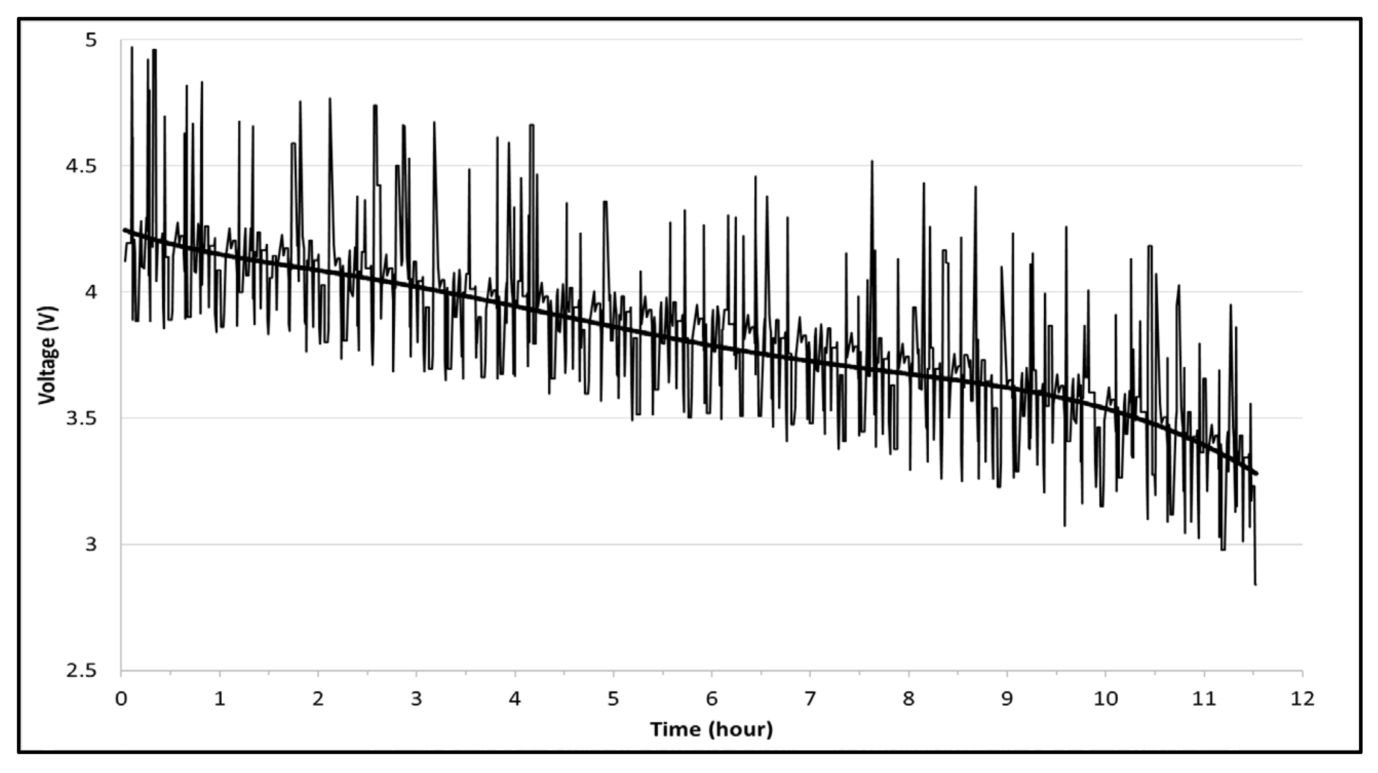
The battery voltage’s evolution with time was also been obtained from experimental tests; Figure 15 shows the results for the same operating conditions shown in Figure 14. It can be noticed that the running times for the evolution of the current and voltage are not the same; this is because the battery was not exhausted after a single cycle, and thus the process was repeated until the battery was completely depleted.
The voltage fluctuations shown in Figure 15 occurred due to the continuous changes in the operating conditions for every i-segment of the trip. Indeed, each time the current varied to simulate the path, there were voltage drops caused by these current variations, which therefore led to this fluctuation phenomenon.
Thus, in order to better visualize the battery discharge curve, a polynomial regression was performed, which allowed the obtention of the voltage trend curve.
If we combine the time evolution of the voltage and current and integrate these over the time, we can obtain the energy driven out from the battery, which can be converted into the driving distance using the correspondingly developed algorithm.
On the other hand, since we know the temperature profile of the route (Figure 13), we can determine the average temperature over the entire route as if the trip was made at a constant temperature; this allows us to evaluate the influence of continuous temperature variation on the driving range.
By doing so, we obtained the global driving range of the simulated trip (Table 1).
The comparison of the two values from Table 1 shows there is a shortening of 43.5 km because of the influence of the variable ambient temperature, and a reduction of 8% in the global driving distance.

5. Conclusions

The present study has analyzed the effect the environmental temperature caused by climatic variability on the performance of an electric vehicle’s battery, and thus on the driving range. The study concludes that changes in environmental temperature modify the driving range of an electric vehicle according to an inverse potential function of the working temperature.
Variable ambient temperatures influence the performance of electric vehicle batteries, reducing their capacity and delivery of energy. The reduction in capacity generates a shortening in the driving range that depends on the fluctuation level of the temperature along the trip.
The influence of the variable ambient temperature on the battery performance was modeled and simulated. A theoretical approach was developed to parametrize the influence of a sudden variation in the ambient temperature on the behavior of an electric vehicle’s battery.
The theoretical approach was validated by means of an experimental prototype that reproduces the real driving conditions of a specific route. The reproduction of real driving conditions was simulated using a control module that commanded a variable resistance, which played the role of the external load, and a temperature module, which played the role of weather environment.
A software program based on developed algorithms was implemented in the control module to faithfully reproduce the real driving conditions; this software was used to set up the simulation conditions and to adjust the variable parameters, when necessary.
The results from the comparison between theoretical approach and experimental values show a perfect match within a 99.89% accuracy. This high correlation value validates the proposed methodology as well as the control software.
The analysis of the results obtained from the simulation process and from the experimental tests shows there is a reduction of 43.5 km in the global driving range for a trip distance of 538 km, which means there is a shortening of 8%. The results correspond to a specific geographical area in the nearby of the city of Lyon (France), for a temperature fluctuation of 39 °C, from −6 °C to 33 °C.
The results of the study can be applied to other geographical areas, although the reduction in driving range may vary according to climatic conditions.

Author Contributions

Conceptualization, C.A.-D.; methodology, C.A.-D.; software, B.B.; validation, C.A.-D. and B.B.; formal analysis, C.A.-D. and B.B.; investigation, C.A.-D. and B.B.; resources, C.A.-D.; data curation, C.A.-D. and B.B.; writing—original draft preparation, C.A.-D.; writing—review and editing, C.A.-D.; visualization, C.A-D.; supervision, C.A.-D.; project administration, C.A.-D.; funding acquisition, C.A.-D. All authors have read and agreed to the published version of the manuscript.

Funding

This research received no external funding.

Institutional Review Board Statement

Not applicable.

Informed Consent Statement

Not applicable.

Data Availability Statement

Data will be provided on request by the corresponding author.

Acknowledgments

Not applicable.

Conflicts of Interest

The authors declare no conflict of interest.

References

  1. Bandhauer, T.M.; Garimella, S.; Fuller, T.F. A critical review of thermal issues in lithium-ion batteries. J. Electrochem. Soc. 2011, 158, R1. [Google Scholar] [CrossRef]
  2. Lu, R.; Yang, A.; Xue, Y.; Xu, L.; Zhu, C. Analysis of the key factors affecting the energy efficiency of batteries in electric vehicle. World Electr. Veh. J. 2010, 4, 9–13. [Google Scholar] [CrossRef]
  3. Ma, S.; Jiang, M.; Tao, P.; Song, C.; Wu, J.; Wang, J.; Deng, T.; Shang, W. Temperature effect and thermal impact in lithium-ion batteries: A review. Prog. Nat. Sci. Mater. Int. 2018, 28, 653–666. [Google Scholar] [CrossRef]
  4. Belt, J.R.; Ho, C.D.; Miller, T.J.; Habib, M.A.; Duong, T.Q. The effect of temperature on capacity and power in cycled lithium ion batteries. J. Power Sources 2005, 142, 354–360. [Google Scholar] [CrossRef]
  5. Lu, Z.; Yu, X.L.; Wei, L.C.; Cao, F.; Zhang, L.Y.; Meng, X.Z.; Jin, L.W. A comprehensive experimental study on temperature-dependent performance of lithium-ion battery. Appl. Therm. Eng. 2019, 158, 113800. [Google Scholar] [CrossRef]
  6. Liao, L.; Zuo, P.; Ma, Y.; Chen, X.; An, Y.; Gao, Y.; Yin, G. Effects of temperature on charge/discharge behaviors of LiFePO4 cathode for Li-ion batteries. Electrochim. Acta 2012, 60, 269–273. [Google Scholar] [CrossRef]
  7. New European Driving Cycle (NEDC). Available online: https://es.wikipedia.org/wiki/New_European_Driving_Cycle (accessed on 22 January 2023).
  8. Emission Test Cycles ECE, 1.5.; +EUDC/NEDC Revision: 2013-07, DieselNet. Available online: https://dieselnet.com/standards/cycles/ece_eudc.php (accessed on 19 January 2023).
  9. World Harmonized Light-Duty Vehicle Test Procedure (WLTP). Available online: https://es.wikipedia.org/wiki/WLTP (accessed on 20 January 2023).
  10. Emissions Standards Reference Guide. EPA Federal Test Procedure, FTP-75, EPA Federal Test: FTP 72/75 (1978)/SFTP US06/SC03 (2008). United States Environmental Protection Agency. Available online: https://www.epa.gov/emission-standards-reference-guide/epa-federal-test-procedure-ftp (accessed on 5 January 2023).
  11. Japanese JC-08 Cycle, Emissions Test Cycles, DieselNet. Available online: https://dieselnet.com/standards/cycles/jp_jc08.php (accessed on 21 January 2023).
  12. Steinstraeter, M.; Heinrich, T.; Lienkamp, M. Effect of low temperature on electric vehicle range. World Electr. Veh. J. 2021, 12, 115. [Google Scholar] [CrossRef]
  13. Iora, P.; Tribioli, L. Effect of ambient temperature on electric vehicles’ energy consumption and range: Model definition and sensitivity analysis based on nissan leaf data. World Electr. Veh. J. 2019, 10, 2. [Google Scholar] [CrossRef]
  14. Lindgren, J.; Lund, P.D. Effect of extreme temperatures on battery charging and performance of electric vehicles. J. Power Sources 2016, 328, 37–45. [Google Scholar] [CrossRef]
  15. Taggart, J. Ambient temperature impacts on real-world electric vehicle efficiency & range. In Proceedings of the 2017 IEEE Transportation Electrification Conference and Expo (ITEC), Chicago, IL, USA, 22–24 June 2017; IEEE: Piscataway, NJ, USA, 2017; pp. 186–190. [Google Scholar]
  16. Pan, C.; Dai, W.; Chen, L.; Chen, L.; Wang, L. Driving range estimation for electric vehicles based on driving condition identification and forecast. AIP Adv. 2017, 7, 105206. [Google Scholar] [CrossRef]
  17. Hao, X.; Wang, H.; Lin, Z.; Ouyang, M. Seasonal effects on electric vehicle energy consumption and driving range: A case study on personal, taxi, and ridesharing vehicles. J. Clean. Prod. 2020, 249, 119403. [Google Scholar] [CrossRef]
  18. Yuksel, T.; Michalek, J.J. Effects of regional temperature on electric vehicle efficiency, range, and emissions in the United States. Environ. Sci. Technol. 2015, 49, 3974–3980. [Google Scholar] [CrossRef]
  19. Ahmed, N.K.; Kapadia, J. Seasonality Effect on Electric Vehicle Miles Traveled in Electrified Vehicles. SAE Int. J. Altern. Powertrains 2017, 6, 47–53. [Google Scholar] [CrossRef]
  20. Dominguez-Jimenez, J.A.; Campillo, J.E.; Montoya, O.D.; Delahoz, E.; Hernández, J.C. Seasonality effect analysis and recognition of charging behaviors of electric vehicles: A data science approach. Sustainability 2020, 12, 7769. [Google Scholar] [CrossRef]
  21. Thiel, C.; Amillo, A.G.; Tansini, A.; Tsakalidis, A.; Fontaras, G.; Dunlop, E.; Taylor, N.; Jäger-Waldau, A.; Araki, K.; Nishioka, K.; et al. Impact of climatic conditions on prospects for integrated photovoltaics in electric vehicles. Renew. Sustain. Energy Rev. 2022, 158, 112109. [Google Scholar] [CrossRef]
  22. Smith, K.; Earleywine, M.; Wood, E.; Neubauer, J.; Pesaran, A. Comparison of Plug-In Hybrid Electric Vehicle Battery Life Across Geographies and Drive-Cycles; National Renewable Energy Lab.(NREL): Golden, CO, USA, 2012; Volume 1, No. NREL/CP-5400-53817.
  23. Pascoe, P.E.; Anbuky, A.H. A VRLA battery simulation model. Energy Convers. Manag. 2004, 45, 1015–1041. [Google Scholar] [CrossRef]
  24. Pattipati, B.; Pattipati, K.; Christopherson, J.P.; Namburu, S.M.; Prokhorov, D.V.; Qiao, L. Automotive Battery Management Systems; IEEE: Piscataway, NJ, USA, 2008; pp. 581–586. [Google Scholar]
  25. Capacity and Battery Ratings Review.Battery Application & Technology. Engineers Edge. Available online: https://www.engineersedge.com/battery/capacity_battery_ratings.htm (accessed on 22 January 2023).
  26. Chen, K.; Li, X. Accurate determination of battery discharge characteristics—A comparison between two battery temperature control methods. J. Power Sources 2014, 247, 961–966. [Google Scholar] [CrossRef]
  27. Park, C.; Lahiri, K.; Raghunathan, A. Battery discharge characteristics of wireless sensor nodes: An experimental analysis. In Proceedings of the 2005 Second Annual IEEE Communications Society Conference on Sensor and Ad Hoc Communications and Networks, IEEE SECON 2005, Santa Clara, CA, USA, 26–29 September 2005; IEEE: Piscataway, NJ, USA, 2005; pp. 430–440. [Google Scholar]
  28. BTU-501: Basics about Discharging. Battery University. 2017. Available online: https://batteryuniversity.com/article/bu-501-basics-about-discharging (accessed on 22 January 2023).
  29. Hausmann, A.; Depcik, C. Expanding the Peukert equation for the battery capacity modeling through inclusion of a temperature dependency. J. Power Sources 2013, 235, 148–158. [Google Scholar] [CrossRef]
  30. Armenta-Déu, C.; Carriquiry, J.P.; Guzmán, S. Capacity correction factor for Li-ion Batteries: Influence of the Discharge Rate. J. Energy Storage 2019, 25, 100839. [Google Scholar] [CrossRef]
  31. Chang, K.T. Geographic information system. In International Encyclopedia of Geography: People, the Earth, Environment and Technology: People, the Earth, Environment and Technology; Wiley-Blackwell: Hoboken, NJ, USA, 2016; pp. 1–9. [Google Scholar]
  32. Longley, P.A.; Goodchild, M.F.; Maguire, D.J.; Rhind, D.W. Geographic Information Systems and Science; John Wiley & Sons: Hoboken, NJ, USA, 2005. [Google Scholar]
  33. Jones, C.B. Geographical Information Systems and Computer Cartography; Routledge: Abingdon-on-Thames, UK, 2014. [Google Scholar]
  34. Thill, J.C. Geographic information systems for transportation in perspective. Transp. Res. Part C Emerg. Technol. 2000, 8, 3–12. [Google Scholar] [CrossRef]
  35. Taylor, P.J.; Johnston, R.J. Geographic information systems and geography. In Ground Truth: The Social Implications of Geographic Information Systems; Guilford Press: New York, NY, USA, 1995; pp. 51–68. [Google Scholar]
  36. Raju, P.L.N. Fundamentals of geographical information system. In Satellite Remote Sensing and GIS Applications in Agricultural Meteorology; World Meteorological Organisation: Geneva, Switzerland, 2006; p. 103. [Google Scholar]
  37. Gibson, R.; Erle, S. Google Maps Hacks; O’Reilly Media, Inc.: Sebastopol, CA, USA, 2006. [Google Scholar]
  38. Mehta, H.; Kanani, P.; Lande, P. Google maps. Int. J. Comput. Appl. 2019, 178, 41–46. [Google Scholar] [CrossRef]
  39. Santos, L.; Coutinho-Rodrigues, J.; Antunes, C.H. A web spatial decision support system for vehicle routing using Google Maps. Decis. Support Syst. 2011, 51, 1–9. [Google Scholar] [CrossRef]
  40. Wang, F.; Xu, Y. Estimating O–D travel time matrix by Google Maps API: Implementation, advantages, and implications. Ann. GIS 2011, 17, 199–209. [Google Scholar] [CrossRef]
  41. Rahman, M.M.; Mou, J.R.; Tara, K.; Sarkar, M.I. Real time Google map and Arduino based vehicle tracking system. In Proceedings of the 2016 2nd International Conference on Electrical, Computer & Telecommunication Engineering (ICECTE), Rajshahi, Bangladesh, 8–10 December 2016; IEEE: Piscataway, NJ, USA, 2016; pp. 1–4. [Google Scholar]
  42. Emirler, M.T.; Wang, H.; Aksun Güvenç, B.; Güvenç, L. Automated robust path following control based on calculation of lateral deviation and yaw angle error. In Proceedings of the Dynamic Systems and Control Conference, Columbus, OH, USA, 28–30 October 2015; American Society of Mechanical Engineers: New York, NY, USA, 2015; Volume 57267, p. V003T50A009. [Google Scholar]
  43. Maharaj, B.S.; King, G. Representative Driving Cycles for Trinidad and Tobago with Slope Profiles for Electric Vehicles. Transp. Res. Rec. 2022, 03611981221138526. [Google Scholar] [CrossRef]
  44. Zhang, Y.; Wang, W.; Kobayashi, Y.; Shirai, K. Remaining driving range estimation of electric vehicle. In Proceedings of the 2012 IEEE International Electric Vehicle Conference, Greenville, SC, USA, 4–8 March 2012; IEEE: Piscataway, NJ, USA, 2012; pp. 1–7. [Google Scholar]
  45. Petal Maps. GPS and Navigation. Available online: https://www.petalmaps.com (accessed on 23 January 2023).
  46. Sygic GPS Navigation & Maps. Available online: https://maps.sygic.com (accessed on 23 January 2023).
  47. Geo Tracker. GPS Tracker. Available online: https://play.google.com/store/apps/details?id=com.ilyabogdanovich.geotracker&pli=1 (accessed on 15 November 2022).
  48. Armenta-Déu, C.; Cattin, E. Real Driving Range in Electric Vehicles: Influence on Fuel Consumption and Carbon Emissions. World Electr. Veh. J. 2021, 12, 166. [Google Scholar] [CrossRef]
  49. Swift, A. Calculation of vehicle aerodynamic drag coefficients from velocity fitting of coastdown data. J. Wind Eng. Ind. Aerodyn. 1991, 37, 167–185. [Google Scholar] [CrossRef]
  50. Sudin, M.N.; Abdullah, M.A.; Shamsuddin, S.A.; Ramli, F.R.; Tahir, M.M. Review of research on vehicles aerodynamic drag reduction methods. Int. J. Mech. Mechatron. Eng. 2014, 14, 37–47. [Google Scholar]
  51. Hucho, W.; Sovran, G. Aerodynamics of road vehicles. Annu. Rev. Fluid Mech. 1993, 25, 485–537. [Google Scholar] [CrossRef]
  52. Wąsik, M.; Skarka, W. Influence of the windscreens inclination angle on the aerodynamic drag coefficient of the cars designed for the race shell eco-marathon based on Numerical simulations. Zesz. Nauk. Inst. Pojazdów Politech. Warsz. 2015, 3/103, 135–141. [Google Scholar]
  53. Armenta-Déu, C.; Giorgi, B. Influence of climatic changes onto the performance of electric vehicles. J. Automob. Eng. Appl. 2022, 9, 43–58. [Google Scholar]
  54. Armenta-Déu, C.; Boucheix, B. Seasonal Temperature Impact on the Driving Range of Electric Vehicles: Effects on Carbon Emission Saving. J. Altern. Energy Sources Technol. 2022, 12, 10–34. [Google Scholar]
  55. Armenta-Déu, C.; Giorgi, B. Analysis of influence of variable meteorological conditions on driving range of EV. Future Transp. 2023; review in process. [Google Scholar]
  56. Boucheix, B. Control of Electric Vehicle Driving Range in Environmental Variable Conditions; Internship Report; Polytech Clermont Ferrand: Aubière, France, 2022. [Google Scholar]
  57. Google Earth. Available online: https://www.google.com/earth/version/ (accessed on 23 May 2022).
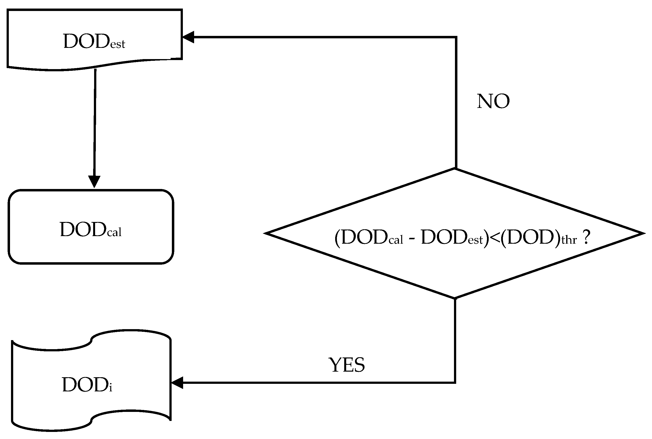
Figure 1. Flowchart of iteration process for DOD calculation.
Futuretransp 03 00031 g001
Figure 2. Flowchart of the modeling process.
Futuretransp 03 00031 g002
Figure 3. View of the Arduino module.
Futuretransp 03 00031 g003
Figure 4. View of the temperature sensor and connection to control module.
Futuretransp 03 00031 g004
Figure 5. View of the SD card for data storage and the assembly to control module.
Futuretransp 03 00031 g005
Figure 6. Assembly diagram of the load section circuit.
Futuretransp 03 00031 g006
Figure 7. Final assembly of the control circuit.
Futuretransp 03 00031 g007
Figure 8. Discharge curve of battery at constant current for various temperatures.
Futuretransp 03 00031 g008
Figure 9. Modified assembly of the control circuit with variable resistance unit.
Futuretransp 03 00031 g009
Figure 10. Schematic view of the simulated power consumption system.
Futuretransp 03 00031 g010
Figure 11. Flowchart of the current adjustment procedure.
Futuretransp 03 00031 g011
Figure 12. Map of the real driving route [54,57].
Futuretransp 03 00031 g012
Figure 13. Temperature profile of the route [54,56].
Futuretransp 03 00031 g013
Figure 14. Comparison between theoretical approach and experimental values for the simulated driving conditions.
Futuretransp 03 00031 g014
Figure 15. Battery voltage’s evolution for the simulated driving conditions.
Futuretransp 03 00031 g015
Table 1. Global driving range of simulated trip.
Constant Ambient Temperature538 km
Variable ambient temperature494.5 km
Disclaimer/Publisher’s Note: The statements, opinions and data contained in all publications are solely those of the individual author(s) and contributor(s) and not of MDPI and/or the editor(s). MDPI and/or the editor(s) disclaim responsibility for any injury to people or property resulting from any ideas, methods, instructions or products referred to in the content.