Abstract
As devices and systems shrink in size, understanding heat transfer at the mesoscopic scale becomes increasingly critical for the design of efficient thermal management strategies. This study investigates convective heat transfer in concentric cylinders, a geometry which is relevant to small-scale technologies. Finite elements simulation are used to examine the influence of geometry and temperature on effective thermal conductivity, and on a parameter introduced as the apparent heat transfer coefficient. It is found that the effective thermal conductivity goes above unity for inner and outer radii at the millimeter scale, which is smaller than that predicted by the available analytical studies. This deviation is attributed to the fact that finite element simulations capture the behavior of temperature boundary layers more accurately at small scales than these analytical models. These insights aid in identifying conditions in which convection can be ignored, significantly simplifying thermal simulations. This work also reveals that at the mesoscale, the ratio between outer and inner radius for which a cylinder can be considered free-standing is much larger than at the macroscale. This highlights the importance of taking the surrounding surfaces into consideration when performing experiments on the heat transfer properties of mesoscale cylinders such as wires.
1. Introduction
Heat transfer between concentric cylinders, also known as annuli, has been extensively studied at the macro scale. In 1975, Raithby and Hollands published seminal work that has become reference work for the theory of convective heat loss for various geometries, including concentric cylinders [1,2]. Their result is expressed by the following equation:
where q is the heat transfer rate per cylinder length, and and are the temperatures on the inner and outer cylinders, respectively. and are the radius of the inner and outer cylinders, and is the effective thermal conductivity of the fluid. This equation is very similar to the exact solution to the concentric cylinder geometry for conductive heat transfer, which can be shown to be
The key parameter change is k, which is the regular thermal conductivity of the fluid. The relation between k and given by the empirical equation
Since the convective heat transfer rate should not be less than the conductive-only heat transfer rate, if Equation (3) yields a result less than one. Furthermore, is the Prandtl number and is the Rayleigh number for the concentric cylinder geometry
where g is the gravitational acceleration, is the volumetric thermal expansion coefficient, is the kinematic viscosity, and is the thermal diffusivity of the fluid. The length scale parameter is given by
It can be seen that scales linearly with the absolute size of , with a less straightforward relation to the relative size of to . The concentric cylinder geometry is shown schematically in Figure 1a, and a plot of as predicted by Equation (3) is shown in Figure 1b.
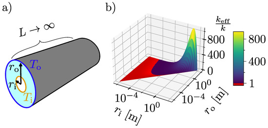
Figure 1.
(a) This shows a sketch of the concentric cylinder geometry, with length L approaching infinity. Note that L and are not directly related. (b) This shows a plot of the result in Equation (3) for air, with 273 K and 283 K. Notice the logarithmic range for and , going from micrometer to meter scale. The red area is where Equation (3) returns values less than one, which can be interpreted as the model predicting that there is only conduction, no convection.
Raithby and Hollands found that Equation (3) holds for a wide range of , relating the equation to the previous experimental studies using air as the fluid by Beckmann, and Grigull and Hauf [3,4].
Although only the temperature difference between and enters into Equations (1) and (4), their absolute values matters indirectly through temperature-dependent material parameters. Thus for a given fluid, three experimental parameters can be used to vary : , , and . The experimental data originally used to verify Equation (3) fit well for . Since a low might entail either a small temperature difference and/or a small geometry, one might assume that this means Equation (3) holds for small scales, as long as continuum equations hold. However, this assumption would be incorrect: the experimental data relied chiefly on varying through , and , with never being below 1 cm. Thus, for small scales with air as the fluid medium, the correlation for has not been tested.
At the same time, in the development of Equation (3), Raithby and Holland assumed that the radial temperature profile in a concentric cylinder geometry can be divided into three parts: two boundary layers close to the surfaces, where the temperature changes rapidly, and one intermediate layer, where the temperature does not change with radial distance. At sufficiently small scales, estimating the size of these boundary layers becomes a chicken-and-egg issue: they are dependent on the heat flux, but the heat flux is dependent on the effective heat transfer coefficient, which is dependent on the size of the boundary layer.
In this work, we define scales small enough for this issue to arise, yet much larger than the mean free path of molecules in air, as the mesoscale. In such scales, ballistic thermal transport can be ignored and basic continuum equations can be utilized, yet previous results based on macroscopic assumptions cannot be taken for granted [5]. The behavior of in air-filled concentric cylinder geometries as and approach the mesoscale has remained largely unexplored and, as such, remains an open question.
Heat transfer on the small scale is becoming ever more relevant, and thus there is now a need to investigate this unsolved issue. On the technological side, the development of MEMS has turned mesoscale heat transfer problems into practical issues of economic significance. On the scientific side, the ever-increasing availability of nano- and microfabrication capabilities among the scientific community has led to more research on small-scale phenomena in general. Whenever this involves temperature differences, heat transfer problems become relevant as potential error sources. Such issues are typically avoided altogether by performing experiments in vacuum [6,7,8]. With a better understanding of small-scale heat transfer in air, one could in some instances avoid such complicated and expensive experimental procedures. Additionally, a solid understanding of small-scale heat transfer at the continuum level helps distinguish between behaviors that fall within the continuum model and those that go beyond it.
Finally, it is relevant to the interpretation of existing experimental works on related systems. While the heat transfer properties of concentric cylinder geometries have not been experimentally examined at small scales, there are some works on the heat transfer properties of nominally free-standing microwires [9,10]. While these works do not examine concentric cylinders, the short distance in absolute terms between microwires and nearest surfaces means that a concentric cylinder geometry can be seen as a relevant first approximation model of the experimental set-ups.
Of course, the fact that the particular system studied in this work has not received substantial attention does not imply that thermal behavior on the small-scale has not been thoroughly examined. From the quantum scale to the mesoscale, small-scale heat transfer has long since become an established field [11,12]. Recent theoretical advances include finite-volume evaluations of forced convection in microchannels for low-global-warming-potential refrigerants [13], a finite-volume comparison of straight and venturi channels for microscale heat exchangers [14], molecular dynamics simulations into the thermal transport of nanostructured solid–liquid interfaces [15], and finite-volume simulations of the solidification behavior of graphene nanoplatelet-based nanofluids [16]. Experimentally, it has recently been demonstrated that one can utilize natural convection to control mass transfer across immiscible liquid boundaries [17], and that micromagnetic convection can be used to enhance mixing in microfluidic applications [18].
In this work, we use the finite element method to investigate the influence of geometry and temperature difference on the convective heat transfer properties of concentric cylinders. Two physical models are built: one assuming conduction as the only heat transfer mechanism, and one explicitly modelling natural convection. The models are built and the heat transfer is evaluated for a large range of , , and . The results are then compared to those predicted by Equation (3).
2. Materials and Methods
A single concentric cylinder geometry was built, as shown in Figure 2a. The geometry consists of two half circles, with the left side using symmetry conditions, thus physically representing two full circles. To enable automatic meshing and simulation of a large number of parameter combinations, and were varied through scaling parameters:
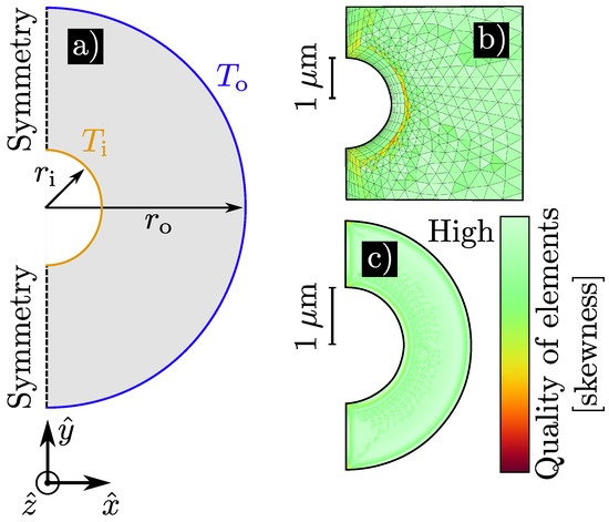
Figure 2.
(a) This shows a schematic of the simulated geometry, where the concentric cylinder geometry has been reduced to a 2D problem “cut in half”, by assuming an infinitely long cylinder with gravity working in negative -direction. (b,c) These are examples of the meshes and their quality, as measured by skewness. (b) This is a magnification of the area surrounding , in a combination of parameters that is challenging to mesh, where . (c) This shows the entire mesh quality of the smallest combination of parameters, where and Mesh outlines are removed for clarity.
Here, , and . scales the entire geometry, while scales the relative distance between the cylinder walls. To cover a large parametric space, and were varied exponentially with between and , and between and .
The boundary situated at is held at , while the temperature at is varied through a temperature difference parameter : , where is varied exponentially between K and K.
Based on these boundary conditions and geometries, two different two-dimensional physical simulation models were built using the commercial finite element software COMSOL, version 6.2. One model considered only heat transfer by conduction, using the heat transfer in solids and fluids COMSOL module. The other model also included convection by laminar flows, using both the heat transfer in solids and fluids module and the laminar flow module. The heat transfer in solids and fluids module solves the equation
where is the thickness of the system, is the density, the specific heat capacity, the translational motion, and T the temperature. Q and contain additional global and local heat sources and is the thermoelastic damping. Finally, the conductive heat flux is
For the laminar flow module, the governing equations are the Navier–Stokes equations. Assuming a weakly compressible, stationary one-phase flow with no turbulence, the relevant Navier–Stokes equations become
and
Here, p is the pressure, is the identity matrix, is the dynamic viscosity, is the surface normal of the boundary, is the volume force vector, and is gravity. Gravity was applied perpendicular to the length of the cylinders.
When combining the laminar flow and heat transfer modules, the viscous heating term is added to the the right hand side of Equation (7):
where is the viscous stress tensor .
The conduction-only model was meshed using only linear, triangular elements, while the convection model also made use of layers of linear rectangular elements, around the boundaries. The finest meshing settings available in COMSOL were used, as these were able to automatically mesh the largest geometry aspect ratios. This was crucial, considering the large parameter space. For the smallest geometrical parameters, this entails a minimum element size of about 80 pm and a maximum size of around 40 nm. For the largest parameter combination, it results in a minimum size of 4 and a maximum size of 2 mm. Generally, this results in good quality elements, with some lower quality elements around the smaller cylinder when . A plot of element quality based on skewness is given in Figure 2b,c.
Material parameters were imported from COMSOL’s materials library for air. The relevant parameters are all included as functions of temperature.
For each combination of parameters, a steady-state simulation was run for each of the physical models, to estimate the the heat transfer Q from the inner to the outer cylinder. Based on this, was calculated as
where is the resulting heat transfer from the convection model, while is the result from the conduction-only model.
It should be noted that also includes conductive heat and therefore represents the total heat transfer. Since the Nusselt number is commonly defined as
is equal to the conventional Nusselt number.
A further caveat is that for the smallest parameter combinations used, 1 and , the Knudsen number becomes
with d being the heat dissipation length and being the mean free path of air molecules, using a conservative value. For this Knudsen number, the validity of Navier–Stokes equations and no-slip boundary conditions are debatable, as the boundary between the continuum flow regime and no-slip flow regime is often considered [19,20]. However, the very smallest systems simulated are of little importance do the overall work presented here, and should they be inaccurate it would not change the overall conclusion.
To verify the mesh independence of the solution, a mesh sensitivity analysis was carried out. Here, the results of and were compared between five different mesh sizes, shown in Table 1. Two different spatial parameter sets were used, both using 10 K: Set 1, using the smallest spatial parameters ( 1 and ) to verify the mesh independence for very small scales. And Set 2, using parameters and cm, where was known to be slightly above unity. This was to verify the mesh independence of the results in a region of the parameter, which is of particular importance to the later discussion. The results of the analysis are shown in Figure 3: For Set 1, the parameters tested hardly varied at all. For Set 2, changed by less than %. This is deemed acceptable, as any differences of comparable magnitude would alter the following results and discussion.

Table 1.
Mesh parameter settings used in the mesh sensitivity analysis.
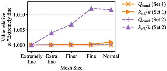
Figure 3.
Mesh-refinement study for two simulation sets. Normalized and are shown as a function of mesh size, from “Extremely fine” to “Normal”. All quantities are scaled by their value at the finest mesh to emphasize relative changes. The tested parameters all vary less than %. Specific mesh settings are given in Table 1.
3. Results and Discussion
Figure 4a shows the evaluated values for for all parameters combinations. It is clear that for most of the parameter space, as long as , and are sufficiently small, . This suggests that for this part of the parameter space, convection plays little role in the heat transfer.
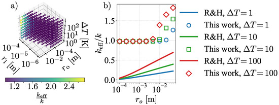
Figure 4.
(a) This shows the simulated value of for all combinations of parameters done. It is evident that the ratio is close to one for most of the parameter space, but increases once exceeds 1 cm. (b) This compares some of the results of this work with those predicted by Raithby and Hollands [1] as a function of , for and 1, 10, and 100 . Compared to their work, we predict the onset of convection for a substantially smaller .
This is qualitatively in line with the analytical model of Raithby and Hollands. To compare, the quantitative predictions of as their analytical solution is plotted in Figure 4b as a function of and compared to our results, for 45.7 , for three different . Our numerical results predict significantly higher than their analytical result. Put differently, our results predict that the transition from convection-dominated to conduction-dominated heat transfer happens for smaller , , and , than those reported by Raithby and Hollands’ model.
To examine the behavior near the transition, we consider twelve cases: keeping and fixed, and varying from to . In Figure 5, velocity contours for the cases are shown. Black lines indicate equithermal lines, set 0.5 K apart. By comparison with Figure 5a, it is clear that the increase in is tied to the establishment of a plume. As increases, the temperature distribution goes from a radial symmetry to one where the almost the entire volume, apart from the plume region, has .
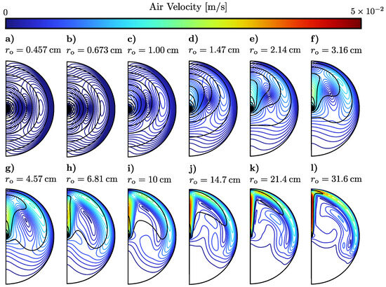
Figure 5.
Velocity (color scale) and temperature (black) contours of twelve different values of , chosen around the point where starts to increase. As the size of the system increases, the velocity of the air circulation increases. K and for all curves.
At the same time, the air velocity in the (establishing) plume region increases gradually, along with the air along the upper edge close to . Meanwhile, the air in the lower half of the cylinder is increasingly more still.
We then plot temperature profiles along a vertical line at for the twelve cases in Figure 5. These are shown in Figure 6a. Equivalent profiles for horizontal lines, at , are given in Figure 6b, and the corresponding values for are shown in Figure 7. It is evident that the boundary layer is tied to : the ratio increases as does, and as increases, the temperature profiles change from a clear exponential relation (appearing linear for a logarithmic x-axis) to two boundary layers separated by a large region of intermediate temperature in the middle.
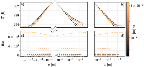
Figure 6.
Visualization of temperature and local Rayleigh number profiles with a single, shared colorbar showing the value of . Top row (a,b): temperature; bottom row (c,d): local Rayleigh number. (a,c) show profiles along the y-axis using a merged logarithmic axis: for the horizontal coordinate is , and for it is . (b,d) show profiles sampled along the x-axis.
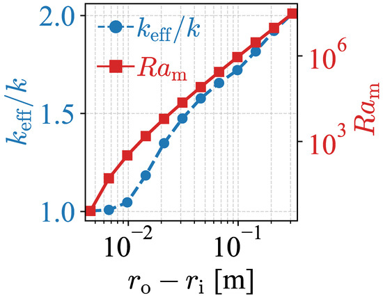
Figure 7.
Comparison between and the modified Rayleigh number () as functions of . Parameters: 45.7 and 10 K.
In Figure 6a, it should be noted that the temperature falls off more rapidly towards the top of the concentric cylinders, compared to the side or to the bottom, where there is no clear outer boundary layer at all. This is consistent with expectations: if one assumes that heat is transferred through the boundary layer primarily by conduction, then by Fourier’s law the thermal transfer is largest where the temperature gradient is largest, which is in the upwards direction.
Based on Figure 6a,b, we estimate the inner temperature boundary layer to be approximately 3 mm for all values of . We use this to attempt to define a new characteristic length, as the difference between the cylinders, by subtracting the thickness of the inner boundary layer 3 mm:
This length is then used to evaluate a local Rayleigh number , defined as
where are global parameters for each simulation, while the rest are evaluated locally based on the temperature-dependent built-in functions. is used as an ideal gas approximation for , as a convenient way to approximate the real value in COMSOL.
Values for along the same lines as the temperature profiles shown in Figure 6a,b are shown in Figure 6c,d. As one would expect, the Rayleigh numbers generally increase as increases with increasing system size. It is also worth noting that seems to increase through the temperature boundary layers, while being quite stable in the intermediate temperature region.
From Equation (16) we go one step further and define a global mesoscopic Rayleigh number, , where all local parameters used in (16) are now replaced with global averages:
The resulting values of as a function of , for the same parameters in Figure 5, are shown along with in Figure 7. For larger values of , is roughly proportional to , before the correlation breaks down at smaller scales. This is similar to the behavior of other concentric cylinder systems, although with a different characteristic length.
To further explore the experimental implication of these results, we define an apparent heat transfer coefficient as
where A is the surface area of the inner cylinder, and is either the conductive or convective total heat transfer between the cylinders.
This is in contrast to the conventional heat transfer coefficient h, which is defined as
The heat transfer coefficient is an interface property dependent only on the properties of a single solid surface and the neighboring fluid. It is thus only a meaningful concept when discussing a free-standing cylinder. For this reason, it is crucial to know whether the experimental regime can be considered free-standing or not trying to experimentally determine heat transfer coefficients. On the macro scale, the transfer between a free-standing cylinder regime and a concentric cylinder one starts to occur more or less when [21]. However, this is not given for the mesoscale. The apparent heat transfer coefficient is the value one would infer when treating an inner cylinder of radius as free-standing, even when the outer boundary at influences the heat transfer.
One way to determine the distance for which the transfer from a concentric cylinder regime to a free-standing wire regime occurs is when becomes constant with increasing . In Figure 8b, is plotted for 100 . It can be seen from the convection simulation results that the apparent heat transfer coefficient for 100 does not reach a stable level before 2 cm for 100 K, and only stabilizes for even larger for lower . This implies that for this particular parameter combination, the free standing regime only starts when —a very large deviation from the macro scale. For lower temperature differences, the deviation is even larger.
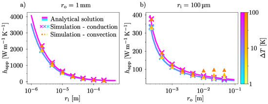
Figure 8 also illustrates the importance of accurate boundary condition control in experiments on microwire heat transfer coefficients. According to our results, the same wire with a radius of 100 can appear to have everything from 50 W/ to 200 W/, depending on the temperature difference and closeness of the surrounding surfaces. Of course, care should be taken not to interpret the figure too literally for these experiments, as the surrounding surfaces typically have a more complex geometry than a perfect radial symmetry.
An important implication of our results is the extent to which conduction-only simulations can replicate the outcomes of convection-inclusive simulations. This finding is valuable given that convection simulations are significantly more complex and computationally demanding. If the size regimes where convection effects are negligible can be reliably identified, conduction-based simulations may serve as an efficient alternative for estimating heat transfer properties in more complex geometries.
To illustrate this point, we plot as a function of , for 1 mm in Figure 8a. As can be seen, the simulation model, the conduction model, and the the analytical model all yield very similar results. Furthermore, they are all able to reproduce the trends experimentally reported by Wang & Tang and by Wang et al. [9,10].
While 1 mm is not, perhaps, a large distance, it is certainly a magnitude that is practical to work with experimentally. Thus, although some more direct experimental comparisons might be required to confirm these numerical results, they nevertheless offer a simple solution in estimating heat loss to air for experiments on the small scale: by ensuring a surface is sitting around 1 mm away from an experimental region of interest, one should be able to accurately model the thermal behavior of the system without needing to include convection.
Another interesting observation is the fact that there is a point of minimum heat transfer. For a given and , it can be seen from Figure 8b that the apparent heat transfer coefficient in the beginning is decreasing for increasing , until it increases slightly again towards the right hand side of the graph. At the turning point, the curvature effect that causes the to increase with decreasing is not very prevalent, yet the convective properties of air have not yet become dominant. This means that for a given , there is a well-defined optimal value for where the heat loss from the inner cylinder is minimal.
For MEMS applications where accurate knowledge of heat transfer to air is necessary, such as electro-thermal actuators [22], we highlight two points that these results suggest. The first regards encapsulated systems. In cases where there are surfaces surrounding the heated object of interest on all sides on a millimeter scale, convection is for practical purposes not a contributing factor to heat dissipation. The second point regards open systems. If a MEMS-device is not encapsulated, but open to the atmosphere on the topside, then convection may significantly increase the thermal dissipation. This would be a particular concern if the thermal resistance of other dissipation mechanisms is high.
Even if the focus in this work has been on air as the fluid, it is possible to make some general conclusions as to how replacing air with another fluid would change the results presented here. Provided that the relevant properties of the replacement fluid are approximately linear over the temperature range investigated, all trends should remain the same. From this, one can use Equations (3) and (4) to predict in which way a change in fluid properties would change the outcome. For instance, for a given parameter combination, a fluid with a higher kinematic viscosity would presumably have a smaller than air, all other things being equal. However, for turbulent conditions or time-dependent cases, the results presented here are presumably inaccurate.
It should be noted that while these results are qualitatively compatible with some experimental studies [9,10,22], a systematic, quantitative experimental verification is lacking and remains to be completed in future work. This could be done for instance by comparing the (apparent) heat transfer coefficient of microwires heated to a temperature 100 K higher than the environment, with diameter 100 surrounded by long, hollow cylinders with radii of 1 mm, 1 cm, and 10 cm. Then compare these experimental results to the analytical conduction model. If the conduction model predicts accurate experimental results at the mm scale, but deviate already at the cm scale, it would be a good validation of these results.
4. Conclusions
This work provides a better understanding of mesoscale heat transfer in air-filled concentric cylinders. Combinations of parameters where heat transfer goes from convection-dominated to conduction-dominated are identified. This transition is substantially different from what previous analytical works suggest: we find that that convection plays a role at smaller sizes and temperature differences than others have found previously. This can be explained by earlier works not properly accounting for the behavior of temperature boundary layers at small scales. Using the finite element method, this is accounted for in our model. Thus, our work can be used in future research to identify parameter combinations where it can be safely assumed that conduction is the main heat transfer mechanism—potentially greatly simplifying modeling of heat transfer problems.
Furthermore, we illustrate for the first time the importance of accurate control of surrounding surfaces when performing small-scale heat transfer experiments. It is shown that a cylinder with a micrometer-scaled radius cannot be assumed to be freestanding unless the nearest surface is at least some hundreds of removed. This is very different from the macro-scale assumption that a cylinder is freestanding if the nearest surface is at least away.
Author Contributions
Conceptualization, T.W.; methodology, T.W.; software, T.W.; validation, T.W.; formal analysis, T.W.; data curation, T.W.; writing—original draft preparation, T.W.; writing—review and editing, J.H. and Z.Z.; visualization, T.W.; supervision, J.H. and Z.Z.; funding acquisition, J.H. All authors have read and agreed to the published version of the manuscript.
Funding
The Research Council of Norway is acknowledged for the support to the Infrastructure project Norwegian Micro- and Nano-Fabrication Facility, NorFab, project no. 295864.
Institutional Review Board Statement
Not applicable.
Data Availability Statement
The raw data supporting the conclusions of this article will be made available by the authors on request.
Conflicts of Interest
The authors declare no conflicts of interest.
Nomenclature
| Parameter | Definition |
| Analytical parameters | |
| A | Surface area of the inner cylinder |
| Volumetric thermal expansion coefficient | |
| Inner temperature boundary layer thickness | |
| g | Gravitational acceleration |
| Apparent heat transfer coefficient | |
| Effective thermal conductivity of the fluid | |
| Characteristic length scale for concentric cylinders | |
| Mean free path of air molecules | |
| Prandtl number, | |
| Rayleigh number for concentric cylinders | |
| Mesoscopic (global) Rayleigh number | |
| Temperatures on inner/outer cylinders | |
| Thermal diffusivity | |
| Temperature difference, | |
| d | Cylinder gap length, |
| h | Conventional heat transfer coefficient |
| k | Thermal conductivity of the fluid |
| Knudsen number, | |
| Effective gap length outside inner boundary layer | |
| Nusselt number | |
| q | Heat transfer rate per cylinder length |
| Local Rayleigh number based on | |
| Radius of inner/outer cylinders | |
| Kinematic viscosity | |
| Parameter | Definition |
| Modeling/numerical parameters | |
| Specific heat capacity | |
| Volume force vector | |
| Identity matrix | |
| Global geometry scale factor | |
| p | Pressure |
| Q | Additional global heat source |
| Total heat transfer (convection model) | |
| Thermoelastic damping heat source term | |
| Conductive heat flux vector | |
| Model base inner/outer radii | |
| T | Temperature field |
| Additional local heat source | |
| 2D system thickness | |
| Gravity vector | |
| Relative gap scaling factor | |
| Dynamic viscosity | |
| Boundary surface normal | |
| Conduction-only heat transfer | |
| Heat transfer between cylinders | |
| Viscous heating (dissipation) term | |
| Density | |
| Viscous (deviatoric) stress tensor | |
| Translational velocity field | |
References
- Raithby, G.; Hollands, K. A General Method of Obtaining Approximate Solutions to Laminar and Turbulent Free Convection Problems. In Advances in Heat Transfer; Elsevier: Amsterdam, The Netherlands, 1975; Volume 11, pp. 265–315. [Google Scholar] [CrossRef]
- Bergman, T.L.; Lavines, A.S.; Incropera, F.P.; Dewitt, D.P. Fundamentals of Heat and Mass Transfer, 7th ed.; John Wiley & Sons, Ltd.: Hoboken, NJ, USA, 2011. [Google Scholar]
- Beckmann, W. Die Wärmeübertragung in zylindrischen Gasschichten bei natürlicher Konvektion. Forsch. Auf Dem Geb. Des Ingenieurwesens A 1931, 2, 213–217. [Google Scholar] [CrossRef]
- Grigull, U.; Hauf, W. Natural Convection in Horizontal Cylindrical Annuli; Begel House Inc.: Danbury, CT, USA, 1966. [Google Scholar] [CrossRef]
- Sobolev, S.L. Non-Fourier heat conduction: Discrete vs continuum approaches. Mech. Res. Commun. 2025, 149, 104512. [Google Scholar] [CrossRef]
- Cheng, Z.; Liu, L.; Xu, S.; Lu, M.; Wang, X. Temperature Dependence of Electrical and Thermal Conduction in Single Silver Nanowire. Sci. Rep. 2015, 5, 10718. [Google Scholar] [CrossRef] [PubMed]
- Lu, L.; Yi, W.; Zhang, D.L. 3ω method for specific heat and thermal conductivity measurements. Rev. Sci. Instru. 2001, 72, 2996–3003. [Google Scholar] [CrossRef]
- Soini, M.; Zardo, I.; Uccelli, E.; Funk, S.; Koblmüller, G.; Fontcuberta i Morral, A.; Abstreiter, G. Thermal conductivity of GaAs nanowires studied by micro-Raman spectroscopy combined with laser heating. Appl. Phys. Lett. 2010, 97, 263107. [Google Scholar] [CrossRef]
- Wang, X.; Guo, R.; Jian, Q.; Peng, G.; Yue, Y.; Yang, N. Thermal Characterization of Convective Heat Transfer in Microwires Based on Modified Steady State “Hot Wire” Method. Es Mater. Manuf. 2019, 5, 65–71. [Google Scholar] [CrossRef]
- Wang, Z.L.; Tang, D.W. Investigation of heat transfer around microwire in air environment using 3ω method. Int. J. Therm. Sci. 2013, 64, 145–151. [Google Scholar] [CrossRef]
- Volz, S.; Carminati, R. Microscale and Nanoscale Heat Transfer, 1st ed.; Topics in Applied Physics; Springer: Berlin/Heidelberg, Germany, 2007; Volume 107, ISSN 0303-4216. [Google Scholar] [CrossRef]
- International Conference on Micro/Nanoscale Heat and Mass Transfer. In ASME 2016 5th International Conference on Micro/Nanoscale Heat and Mass Transfer: 4–6 January 2016, Singapore: Volume 1: Micro/Nanofluidics and Lab-on-a-Chip; Nanofluids; Micro/Nanoscale Interfacial Transport Phenomena; Micro/Nanoscale Boiling and Condensation Heat Transfer; Micro/Nanoscale Thermal Radiation; Micro/Nanoscale Energy Devices and Systems; American Society of Mechanical Engineers: New York, NY, USA, 2016.
- Moya, D.A.; Moraga, N.O.; Sempértegui-Tapia, D.F.; Chávez, C.A. 3-D numerical simulation of forced convection heat transfer in microscale rectangular channels for low GWP refrigerants. Numer. Heat Transf. Part A Appl. 2025, 86, 8873–8891. [Google Scholar] [CrossRef]
- Pandey, V.K.; Negi, V.P.S.; Ranganayakulu, C. Comparative Study of Straight and Venturi Channel Cross Sections of Microchannel Heat Exchangers. J. Therm. Sci. Eng. Appl. 2024, 16, 091007. [Google Scholar] [CrossRef]
- Li, H.; Wang, J.; Xia, G. Thermal Transport through Solid-Liquid Interface: Effect of the Interfacial Coupling and Nanostructured Surfaces. J. Therm. Sci. 2022, 31, 1167–1179. [Google Scholar] [CrossRef]
- Chen, K.T.; Li, Q.Y.; Takahashi, K. Slip Flow on Graphene: Current Status and Perspective. J. Therm. Sci. 2022, 31, 1115–1134. [Google Scholar] [CrossRef]
- Wang, J.; Zhang, L.; Hassanpouryouzband, A.; Sun, X.; Liu, Y.; Zhao, J.; Song, Y. Thermal Marangoni natural convection enables directional transport across immiscible liquids. Nat. Commun. 2025, 16, 5727. [Google Scholar] [CrossRef] [PubMed]
- Kitenbergs, G.; Cēbers, A. Rivalry of diffusion, external field and gravity in micro-convection of magnetic colloids. J. Magn. Magn. Mater. 2020, 498, 166247. [Google Scholar] [CrossRef]
- Dongari, N.; Sharma, A.; Durst, F. Pressure-driven diffusive gas flows in micro-channels: From the Knudsen to the continuum regimes. Microfluid. Nanofluid. 2009, 6, 679–692. [Google Scholar] [CrossRef]
- Tsalikis, D.G.; Mavrantzas, V.G.; Pratsinis, S.E. Dynamics of molecular collisions in air and its mean free path. Phys. Fluids 2023, 35, 097131. [Google Scholar] [CrossRef]
- Atayılmaz, Ş.Ö. Experimental and numerical study of natural convection heat transfer from horizontal concentric cylinders. Int. J. Therm. Sci. 2011, 50, 1472–1483. [Google Scholar] [CrossRef]
- Zhu, H.; Cao, Y.; Ma, W.; Kong, X.; Lei, S.; Lu, H.; Nie, W.; Xi, Z. Dynamic Modeling of a MEMS Electro-Thermal Actuator Considering Micro-Scale Heat Transfer With End Effectors. J. Microelectromech. Syst. 2024, 33, 217–226. [Google Scholar] [CrossRef]
Disclaimer/Publisher’s Note: The statements, opinions and data contained in all publications are solely those of the individual author(s) and contributor(s) and not of MDPI and/or the editor(s). MDPI and/or the editor(s) disclaim responsibility for any injury to people or property resulting from any ideas, methods, instructions or products referred to in the content. |
© 2025 by the authors. Licensee MDPI, Basel, Switzerland. This article is an open access article distributed under the terms and conditions of the Creative Commons Attribution (CC BY) license (https://creativecommons.org/licenses/by/4.0/).