Article

Determination of Optimal Piston Trajectories for High Efficiency 4-Stroke Cycles by Using Predictive Combustion Modeling

Chair of Integrated Modelling of Efficient Powertrains, Technische Universität Berlin, Carnotstraße 1a, 10587 Berlin, Germany
*
Author to whom correspondence should be addressed.
Thermo 2022, 2(4), 352-370; https://doi.org/10.3390/thermo2040024
Submission received: 7 September 2022 / Revised: 30 September 2022 / Accepted: 3 October 2022 / Published: 13 October 2022

Abstract

:
The potential regarding the indicated efficiency of an alternative piston trajectory for a spark ignited methane combustion engine has been investigated in this study. A physics-based cylinder model including a predictive combustion model was used to account for the interaction of the thermodynamics with altered kinematics. Using a genetic optimization algorithm on an adjustable spline, piston trajectories for different piston acceleration limits have been found for both full and part load operating points. All optimization processes led to increased indicated efficiencies up to a maximum of 52%. The increase in efficiency of the optimized piston trajectory is analyzed based on the results of the numeric simulation and can be explained by the following effects: deeper expansion of the working gas, reduced pumping losses, reduced wall heat losses, shorter heat release, and increased trapped air mass.

1. Introduction

Even while considering alternative, CO2-neutral fuels, the relatively low efficiency of conventional internal combustion engines (ICE), compared to other energy converters like electric machines, is one of its main drawbacks. Through many decades of development, the current design of modern ICE has reached a high level of optimization that reduces the potential for further significant efficiency gains. The piston kinematics constrained by crank shaft and connecting rod has been seen as a fundamental basis. While parameters have been optimized, the kinematic principle has not been changed. Although attempts to introduce new variants of the traditional design have been proposed, none of these were commercially successful. At the same time, it is known that the kinematics of the piston has great effects on the performance of an ICE. Famously, Atkinson proposed a more complex crank drive to achieve higher efficiencies by introducing different expansion ratios for intake and compression compared to expansion and exhaust. The current dynamic in the automotive industry allows for considering new alternatives regarding propulsion. There are numerous combustion engine concepts that allow for alternative piston trajectories, most famously represented by free-piston engines. For those, due to the lack of a mechanical power transmission, the piston movement is mainly determined by the gas forces. Additionally, linear electric machines can act on the piston in order to control its movement and to extract work from the process. There are also other engine concepts that allow for a more flexible design of the piston trajectory via mechanical kinematics.

1.1. Goal and Approach

This paper investigates the potential gains in ICE efficiency through allowing unconventional piston trajectories for a 4-stroke spark ignited engine. The assessment is carried out through numerical engine process simulation in combination with a parameterizable piston trajectory. A thermodynamic single cylinder model with a predictive combustion model (CH4 as a fuel) is used to physically resemble the interaction of the piston movement with the combustion process. Following a preliminary study in Matlab/Simulink, the model was set up and run in GT-Suite, a commercial software for engine process simulation. After carrying out a sensitivity analysis on the piston trajectory parameters and establishing appropriate boundary conditions, a genetic optimization algorithm is used to determine the parameters for the highest indicated thermal efficiency.
The topic of optimal piston trajectories has been addressed in literature before. However, the approach presented here is novel due to two main aspects. First, the predictive combustion modeling is a central part of the approach. In many cases, optimal control theory is used to determine an optimal piston trajectory, such as in Mozurkewich et al. [1] and Huleihil et al. [2]. These approaches however neglect the physical combustion process. In other cases, instantaneous heat releases or simple Wiebe functions are assumed. All of these approaches do not seem suitable to accurately predict a realistic combustion behaviour of the ICE. As a result, this paper uses a state of the art entrainment model to represent combustion and achieve realistic simulation results, including the interaction of combustion with the piston movement. Second, in this study, no specific mechanical solution on how to implement the optimized piston trajectory is given or presumed. Consequently, design specific boundary conditions such as, for example, gas springs, linear electric machines or limited valve timing variability, are not taken into consideration.

1.2. Motivation

As analysis of losses in conventional ICE shows, a large part of the thermal energy escapes the cylinder in the form of hot exhaust gas instead of being converted into useful work by the piston. Modern engine concepts can utilize parts of this energy through turbocharging, in which the turbine converts exhaust gas enthalpy into mechanical energy to power a compressor. However, a direct utilization in the cylinder through a prolonged expansion stroke, as famously proposed by Atkinson [3], offers higher potential for optimal energy utilization. Unfortunately, the conventional ICE crank drive design does not allow a variation of the expansion ratio, which is defined as
ε = V h + V c V c ,
where V h is the displacement volume and V c is the clearance volume of the piston.
Another large share of energy escapes from the cylinder in the form of wall heat losses. Since these are a function of temperature difference, surface area, time and a heat transfer coefficient, which in turn depends on the geometry, gas flow situation and material properties, it is expected that the piston trajectory also offers further potential for improvement in that regard.
Additionally, the gas exchange in a conventional 4-stroke engine concept requires mechanical power from the crank shaft. It is expected that these pumping losses might offer potential for optimization since they rely on the piston movement and valve timing.
Lastly, the combustion process itself might differ from conventional engines, since there is a strong interaction with the piston movement. Due to the physics-based phenomenological modeling approach, this numerical study should be able to identify potentials for an efficiency gain through the combustion process as well.

1.3. Background and State of the Art

1.3.1. Atkinson and Miller Cycle

Atkinson [3] proposed an alternative crank drive design to allow different expansion ratios for intake and compression compared to expansion and exhaust. However, the kinematics are complex and difficult to implement due to their unfavourable power transmission. Today, the Miller and Atkinson cycles are integrated through variable valve lifts and timings. Both approaches aim to reduce the air mass at intake valve closing without utilizing a throttle, which would normally result in additional pumping losses during part load engine operation. The Atkinson cycle achieves this by closing the intake valve late, while the Miller cycle uses early intake valve closing. As a result, the effective compression ratio is lowered. In combination with an optimal spark, timing the expansion now benefits from a relatively higher expansion ratio. In addition to the de-throttling at part load, these concepts can also be applied to full load by transferring some of the needed compression to turbocharger and intercooler. Variable valve timings have been implemented successfully into modern engines and can offer up to 15% reduction in specific fuel consumption [4] (pp. 119–121).

1.3.2. Free-Piston Engine Concepts

As an alternative to the traditional crank drive, free-piston engine concepts offer almost complete freedom regarding the trajectory of the piston. In these machines, the piston is not guided by predefined mechanical kinematics, but moves only as a result of the forces acting on it. In most cases, gas springs are utilized at the end positions. Linear electric machines can apply a magnetic force on the piston in order to extract work and to control the piston movement. While the freedom of the piston trajectory can result in high thermodynamic efficiencies, the concept is often limited by the capabilities of the electric machine and the difficulty to precisely control the piston movement.
Due to the flexibility of free-piston engines, a range of studies has been done on optimal piston trajectories. Numerical investigations in combination with optimal control theory provide the basis of their methodology in many cases [5,6,7,8]. However, in many studies, the interaction of the altered piston movement with the combustion process is being neglected. Instead, Lin et al. [6] use predefined heat releases via Wiebe functions and Ge et al. [5] assume an instantaneous heat release. These approaches drastically lower the confidence level of their predictions. On the other hand, in another study by Xu et al. [7], physics-based 3D CFD calculations are used for the cylinder and combustion model. While this approach offers a higher prediction accuracy, only three piston trajectories have been analysed due to the large computational effort. Zhang et al. [8] use a physics-based 0D cylinder model including chemical reaction mechanisms to determine an optimal piston trajectory, which provides an approach very similar to the one presented in this study. However, due to their opposed-piston opposed-cylinder two-stroke engine, the piston trajectory is limited to a symmetric path without the possibility to differentiate between compression and expansion ratio. Within these constraints, they were able to determine alternate piston trajectories for different fuel types with very significant efficiency gains, which can be seen as a promising motivation for the study presented here.

1.4. Existing Methods for the Alteration of the Expansion Ratio

There are several proposals for mechanical solutions of an alteration of the compression ratio. Both Robert [9] and Asthana et al. [10] present comparative studies of advancements for different mechanical solutions for variable compression ratio (VCR) engines. Some allow a quasi-static variation and therefore address the optimization of the expansion ratio for different engine operating points, especially between high and low loads. However, these are not capable of changing the expansion ratio periodically within one working cycle and consequently are not being considered as an appropriate solution. Other concepts that do allow two different stroke lengths within each working cycle are better suited in the scope of this study. However, these still lack the capability to also change the stroke timing as well as the shape of the piston trajectory. Both authors come to the conclusion that VCR engines, even within those constraints, offer significant potential for efficiency gains but also point out the difficulty to bring more complex mechanical kinematics into mass production due to incompabilities with existing manufacturing processes.
Active Combustion Chamber (ACC) engines offer another way to dynamically alter the volume of the combustion chamber and thus the compression/expansion ratio. In a simulative study, Dabrowski et al. [11] present the innovative concept of a pneumatic energy accumulator. This approach offers advantages in terms of efficiency in comparison to the reference engine due to a higher compression ratio. However, a fully variable piston trajectory is less limited in terms of the achievable compression and expansion ratio, the variability of the combustion chamber volume evolution, combustion control and especially regarding the individual phase lengths. Moreover, drastic changes to the combustion chamber shape, as for example with the introduction of an additional piston into the cylinder head, lower the confidence of prediction accuracy for established modeling approaches.

2. Methods

The analysis of this paper does not presume or specify a specific solution on how the optimal piston trajectory is achieved. However, underlying this study, there exists an undisclosed new engine concept that is capable of a freely configurable piston trajectory incorporating a mechanical connection between the piston and the transmission shaft. Specific boundary conditions of free-piston engines, such as a gas spring and the electrical machine, are not being considered.
As stated above, this study aims to resemble the interaction of the piston movement with the combustion process by employing a physics-based phenomenological predictive combustion model. A numerical forward simulation of the cylinder thermodynamics in GT-Suite serves as a basis for further evaluation of the engine efficiency. Due to the low computational costs of this approach, an optimization algorithm can test out more than one thousand designs per hour on a conventional PC. The genetic algorithm that is used in GT-Suite is NSGA-III, proposed by Deb et al. [12], which is an evolutionary, global search algorithm. While the underlying modeling library of the GT-Suite software is documented in the user manuals [13,14] to some extent, the main equations on which the physics-based cylinder and combustion model are based on, are described briefly in the following section.

2.1. Modeling

2.1.1. Cylinder

The Cylinder is modeled as a zero-dimensional gas container/reactor employing the mass balance
d m c d t = d m i d t d m o d t ,
where m c is the mass of gas in the cylinder and d m i and d m o are the mass flows through the inlet and outlet valves. It is assumed that blow-by losses can be neglected for the scope of this study.
The energy balance is based on the first law of thermodynamics for an open, unsteady system
d E = d Q + d W + h i + c i 2 2 + g z i d m i h o + c o 2 2 + g z o d m o ,
which can be transformed into an expression for the cylinder temperature
d T c d t = 1 m c c v d Q f d t d Q w d t p d V d t + h i d m i d t h o d m o d t u d m c d t m c j u j d y j d t ,
where m c c v is the heat capacity of the gas in the cylinder, d Q f is the heat release from the fuel, d Q w is the wall heat loss, p d V is the work by the piston, h i / o d m i / o are the enthalpy flows through the valves, u is the internal energy and y j is the mass fraction of the gas components.
For the calculation of the pressure, the ideal gas law
p V = m R s T
is used.
The caloric material values of the gas components were determined using NASA polynomials by McBride et al. [15].
The wall heat losses are calculated according to the Newtonian approach for convective heat transfer
d Q w d t = i 3 α A w , i T w , i T c ,
where α is the heat transfer coefficient, A w , i are the wall areas of piston, bore and cylinder head, and T w , i are the respective average wall temperatures. The heat transfer coefficient is estimated based on the approach of Woschni [16] with
α = 130 d 0.2 p c 0.8 T c 0.53 C 1 c m + C 2 V h T 1 p 1 V 1 p c p m ,
where d is the bore diameter, c m is the mean piston speed, T 1 , p 1 and V 1 describe the gas state at inlet valve closing, p m is the theoretic cylinder pressure during motoring operation, and C 1 and C 2 are constants.

2.1.2. Combustion

A predictive entrainment model (SI-turb) is used to model the combustion. It offers a quasi dimensional phenomenological combustion model which aims to resemble the most influential chemical and physical aspects and processes of combustion. Consequently, more accurate simulation results can be obtained while maintaining low computational effort for the engine model.
The model differentiates two zones: an unburned and a burned zone. Both zones for themselves assume homogeneity regarding temperature and gas composition. During combustion, mass flows from the unburned to the burned zone. The cylinder pressure is assumed to be identical in both zones. In addition to that, the entrainment model introduces an additional flame zone. It is assumed that a spherical flame front spreads into the unburned zone, creating the flame zone. The flame zone is part of the unburned zone and thus does not have its own thermodynamic state regarding temperature, pressure and mass fraction. Only a mass balance is calculated for the flame zone to determine the burn rate. The concept is visualized in Figure 1.
In this model, two processes occur simultaneously: firstly, the entrainment mass flow d m e / d t of unburned gas enters the flame zone as the flame front area A FF advances with the sum of the laminar and the turbulent flame speed:
d m e d t = ρ u A FF s L + s T ,
where ρ u is the density of the unburned zone, and A FF is the surface area of the flame front. Secondly, the mixture within the flame zone burns which creates a mass flow d m b / d t from the flame zone into the burned zone. This mass flow resembles the burn rate and is proportional to the amount of unburned mixture in the flame zone, divided by a time τ :
d m b d t = m e m b τ ,
where m e is the entrained mass (mass of flame zone and burned zone), m b is the mass of the burned zone, and τ is the characteristic burn duration. In order to determine these values, a series of additional equations needs to be considered, as described in the following.
The modeling approach assumes that the characteristic burn duration is based on the size of a fresh gas vortex with a diameter in the range of the Taylor-micro-length λ and the laminar flame speed s L :
τ = λ s L
with
λ = L i R e t ,
where L i is the integral length scale, and R e t is the turbulent Reynolds number.
The turbulent and laminar flame speeds have a high impact on the combustion model and consequently are estimated based on several parameters.
The equation for the laminar flame speed for methane, which is an adaptation of the calculation of the laminar flame speed for gasoline from Heywood [17] (pp. 402–405), is given by the GT Suite help menue [18] as
s L = B m ϕ η e ξ ϕ ϕ m 2 T u T ref α p p ref β f ( y res ) ,
where B m is the maximum laminar speed, ϕ is the equivalence ratio, η is the equivalence ratio exponent, ξ is the laminar speed exponent, ϕ m is the equivalence ratio at maximum speed, T u is the temperature of the unburned zone, p is the cylinder pressure, α and β are exponents for temperature and pressure and lastly T ref and p ref are reference values. Additionally, a dilution function is considered as
f ( y res ) = 1 0.75 ( 1 ( 1 0.75 · y res ) 7 ) ,
where y res is the residual mass fraction in the unburned zone [18].
The turbulent flame speed is determined by
s T = u 1 1 1 + R f L i 2 ,
where u is the turbulence intensity, and R f is the flame radius. The turbulence intensity is highly dependent on the piston speed.

2.1.3. Flame Front Area

The determination of the flame front area A FF follows the approach presented in [19]. This method assumes a spherical expansion of the flame while considering the geometry of the cylinder, including piston position and the piston shape. The flame front area is a function based on the progress of the combustion, which is determined by the ratio of the volume of the burned zone to the total volume:
x vol = V b V total
In order to accelerate the simulation, the flame front area for all combinations of piston position x P and volume ratio of the burned zone x vol are precalculated and stored in a map:
A FF = f ( x vol , x p )

2.1.4. Heat Release

In this study, it is assumed that the heat release is a direct result of the conversion of substances in the chemical reaction within the energy balance of the burned zone:
d T b d t = 1 m b c v , b p d V d t d Q w , b d t + h u d m e d t u b d m b d t m b j u j d y j d t
Based on the global reaction equation of a methane combustion,
CH 4 + 2 O 2 2 H 2 O + CO 2 ,
the changes in the gas mixture composition are calculated.

2.1.5. Model Validation

The combined cylinder and combustion model is validated through engine test bench data of the conventional engine setup. The reference engine has a displacement volume of 333 cm 3 per cylinder and a compression ratio of 12.8 . Only two engine operating points are being considered in this study. Table 1 shows the differences between the experimental measurement data and the simulation results. Regarding the center of heat release and the burn duration, the simulation shows good agreement with the measurement. This is important since the validation of the predictive entrainment model for the combustion is essential to this study. In terms of indicated mean effective pressure, only moderate agreement is observed, especially for the part load operating point. This is expected to some extent, since neither the valve timings of the original engine nor any parts of the air path are modeled in this study. As a result, the trapped air mass is different, which affects the indicated mean effective pressure.

2.1.6. Piston Kinematics

In a traditional crank drive, the movement of the piston can be described by
x p ( φ ) = r 1 + R cos φ R 1 1 R 2 sin 2 φ ,
where r is the crank radius (or ½ of the stroke), R is the connecting rod to crank radius ratio and φ is the crank angle. Based on that, the cylinder volume can be calculated by
V cyl ( φ ) = V c + A c · x p ( φ ) .
where A c is the cross-sectional area of the cylinder.
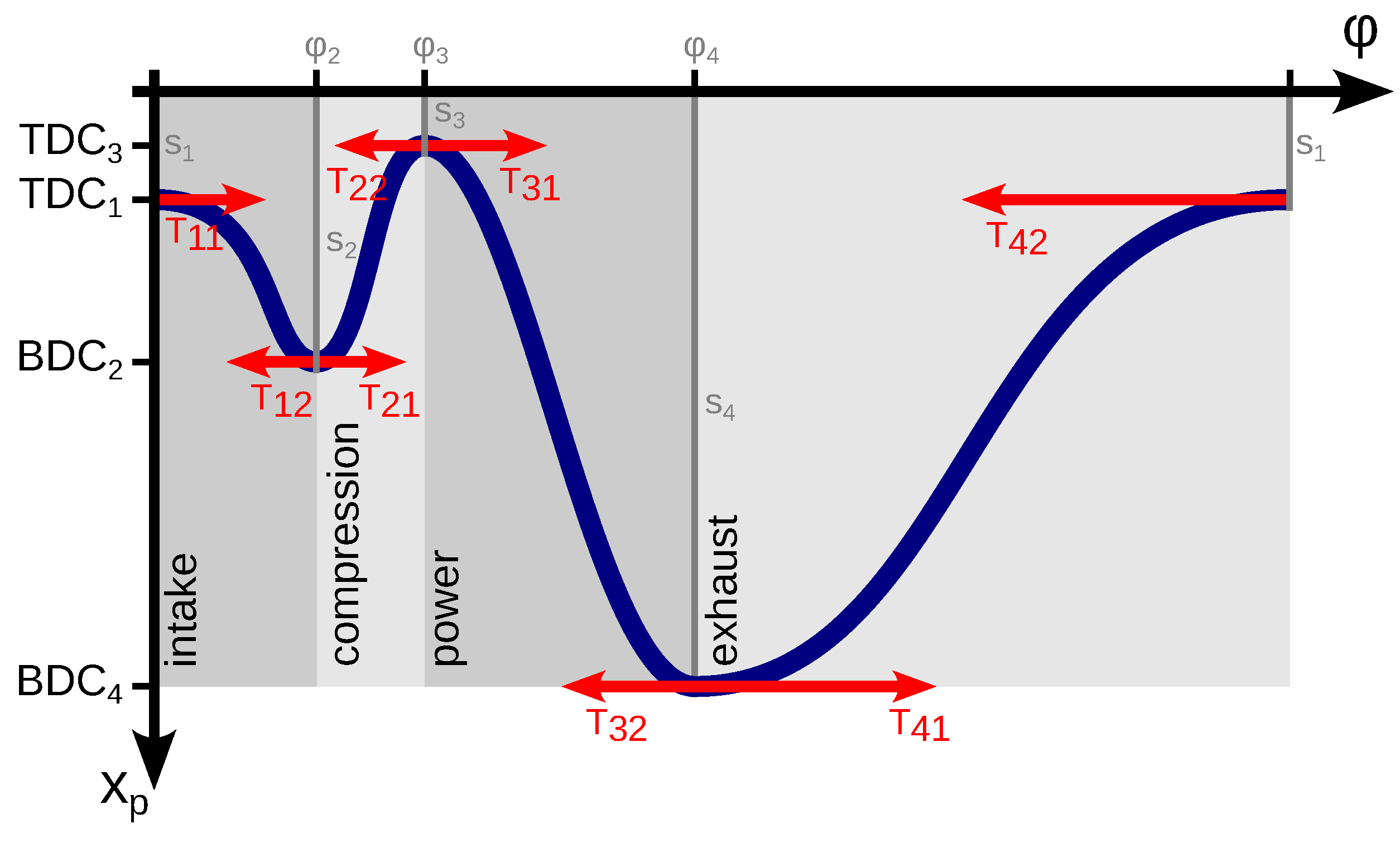
In this study, it is assumed that a freely configurable piston trajectory can be achieved by the engine kinematics. In order to identify the most efficient piston trajectory, a highly flexible spline function is used. The primary boundary condition is a 4-stroke cycle, whereas the length of each stroke, the piston end positions of each stroke as well as the shape of the piston trajectory between two end points can be modified by parameters, as shown in Figure 2. The use of cubic Hermite spline functions provides a continuously differentiable piston trajectory. Additionally, it allows for specifying a slope of zero at the start and end of each stroke, which is convenient for defining the turning points. The magnitude of the tangents is also used to change the shape. Additional boundary conditions for the piston trajectory, such as maximum piston speed, acceleration and maximum piston displacement, are implemented.
As an example, based on [20], the cubic Hermite spline interpolation polynomial for the intake phase can be written as
P ¯ = P A P 2 P 3 P B = ( x A , y A ) ( x 2 , y 2 ) ( x 3 , y 3 ) ( x B , y B ) = z 3 z 2 z 1 · 2 2 1 1 3 3 2 1 0 0 1 0 1 0 0 0 · A B T A T B .
P ¯ is a matrix which contains all points of the cubic Hermite spline interpolation. The generic coordinate pairs of x and y for each point on the curve represent discrete pairs in terms of the crank angle φ and the piston position x p in this study. z is a vector with an arbitrary number of discrete values between 0 and 1. This determines the discretization level of the spline interpolation. A is the starting point of the spline at z = 0 , and B is the end point of the spline at z = 1 . T A is the tangent at the starting point, and T B is the gradient at the end point. Four cubic Hermite splines are used, representing the four strokes of the ICE. The end point of each stroke is identical with the starting point of the following one. The second component of all tangents is zero in order to achieve a gradient of zero at the turning points of the piston trajectory.

2.2. Optimization and Simulation Setup

The 15 parameters of the piston trajectory (eight tangents, four piston end point positions and three stroke start crank angles) are handed to an optimization algorithm that uses the cylinder model to determine the engine efficiency. A piston trajectory corresponding to a traditional crank drive is defined as the initial parameters for the optimization.
The simulation of each design includes a gradual variation of the spark timing. This way, the optimal ignition timing for each piston trajectory is determined. The results of the simulation for the spark timing with the highest indicated efficiency are then interpreted as the case result for the current design by the genetic optimization algorithm.
During the simulation, additional thermodynamic boundaries such as maximum cylinder pressure and knocking are being accounted for. The knocking model used in this study is based on [21]. In this approach, an integral over temperature and pressure within the cylinder is used to determine the pre-reaction level of the unburned zone and compares this to a critical value.
Valve lifts and timings were implemented in a way that they automatically adjust to the stroke lengths, which means that the opening and the closing process was completed normally when enough time is available. Otherwise, the valves would not open fully before closing again. If more time is available for regular opening and closing during the stroke, the valve remains in the open position for an additional time accordingly. This principle is illustrated in Figure 3. Valve overlap is not considered in this study as its relative impact is assumed to be small compared to other parameters, also taking into account the additional computational effort required for the optimization.
Two different engine operating points have been selected—full load as well as part load, where the part load point is defined as 50% of the maximum power output of the standard engine, resulting in an intake air pressure of 583 mbar. Full load refers to boundary conditions of 1 bar pressure at cylinder inlet as well as the cylinder outlet—assuming a naturally aspirated engine. Since it is difficult to determine the pressure boundaries for a supercharged engine in combination with a heavily modified piston trajectory, no simulations for charged engine operation are conducted. The engine speed is kept constant. Inlet air temperature is set to 300 K.
The maximum piston acceleration is an important boundary condition that needs to be considered due to the associated mass forces. When the piston trajectory is changed, starting from the conventional crank drive to the optimum shape, the piston acceleration increases significantly. As a result, the limitation of the piston acceleration is part of the optimization process. Optimization runs are carried out for different acceleration limits down to 7300 m/s2, which is the maximum piston acceleration of the conventional crank drive. Additionally, an optimization without the limitation of the acceleration is done as well.
The piston velocity is another relevant boundary condition in regard to lubricity and friction losses constraints. In this study, two repetitions of the entire optimization process are done. The first run sets an unrealistic high piston velocity limit of 100 m/s (GT-Suite does not allow higher piston velocities) in order to investigate the effects of the acceleration limit alone on the important engine parameters. Afterwards, the optimization process is repeated with a maximum piston velocity limit of 44 m/s. This value is taken from the Audi V10 5.2 l FSI engine—a high performance engine with a mean piston speed of 26.9 m/s, which was in series production [22] (pp. 16–19). In the discussion of results, all cases that breach the piston velocity limit of 44 m/s are indicated.
Another significant constraint is set regarding the compression stroke. The displacement values for the start of compression and end of compression are kept constant according to the reference case. This way, the compression ratio of the reference engine of 12.8 is maintained. As a result, the combustion process for all alternative piston trajectories should differ less from the reference case and consequently the simulation accuracy should benefit. It is accepted at this point that this constraint may possibly reduce the potential for efficiency gains during the optimization process, but the higher confidence level is preferred.

3. Results and Discussion

The results of the simulation of the new piston trajectories are compared to the results from the conventional crank drive, which serves as reference cases for both full and part load operation. The parameters of all optimized piston trajectories are provided in Appendix A.

3.1. New Piston Trajectory Characteristics

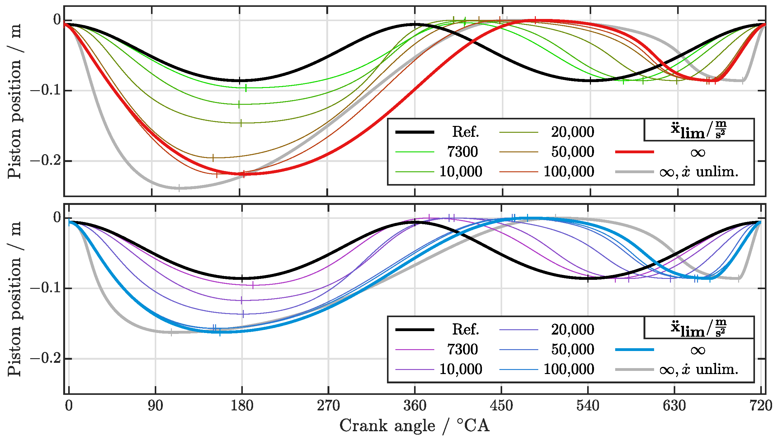
First, the general shape of the optimized piston trajectories is discussed. Figure 4 shows the optimized piston trajectories for both full and part loads for different maximum piston accelerations, including an unlimited optimal case. Additionally, the trajectory of the conventional crank drive is given as a comparison. It is noted that most of the optimized piston trajectories for different simulation parameters share the same general characteristics which are most pronounced in the optimized piston trajectory that was unlimited in both piston acceleration and piston velocity. These characteristics are discussed in the following section based on a detailed analysis of the simulations results.

3.1.1. Expansion Ratio

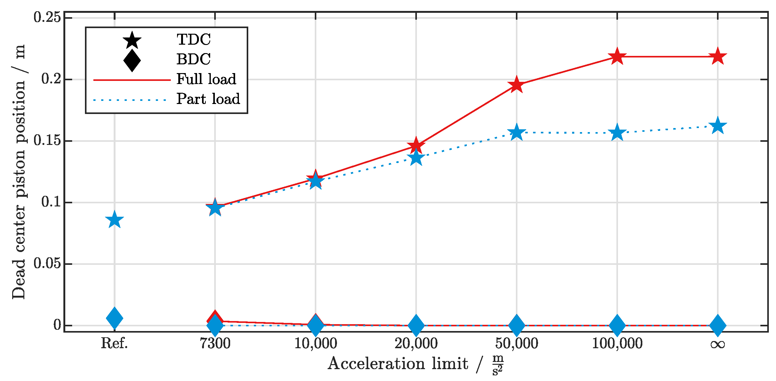
A large difference between the compression ratio and the expansion ratio is observed. Since the compression ratio is kept constant during the optimization, the piston now expands much further during the power stroke. Figure 5 shows the evolution of the top and bottom dead center positions during the optimization with increasing acceleration limits. The distance to the bottom dead center is doubled for part load and tripled for full load to allow high expansion ratios. By contrast, the clearance volume at the top dead center during gas exchange is minimized. This results in a low amount of residual unburned gas and in turn maximizes the amount of air in the cylinder at intake valve closing.
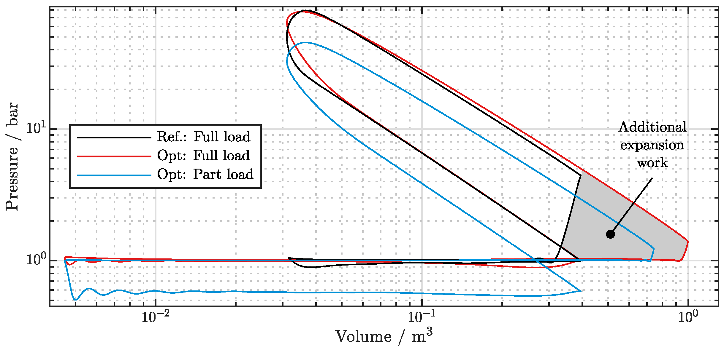
The high displacement during combustion was expected since the higher expansion ratio allows prolonged energy extraction from the working gas. This becomes apparent when comparing the conventional crank drive to the new concept in the p-V-diagram, as shown in Figure 6. The enclosed area of the high-pressure phase, which is proportional to the volume work, is much larger due to the extended expansion.

3.1.2. Stroke Timing

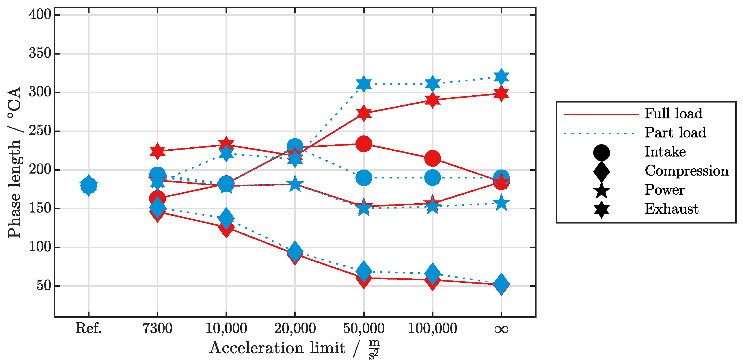
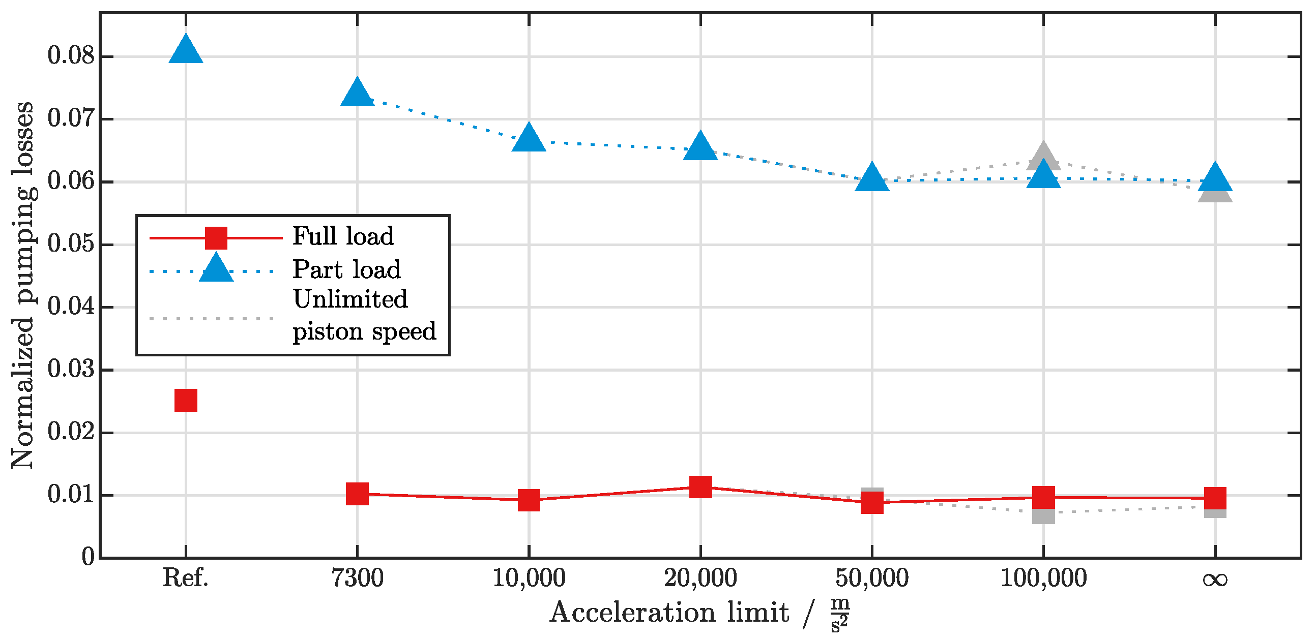
The lengths of the individual phases have shifted relatively within the working cycle, as can be seen in Figure 7. The phases for gas exchange, both intake and exhaust, are longer in comparison with their according countermovements of the piston. More time for gas exchange leads to lower mass flows, which in turn result in smaller pressure gradients across the valves. This results in lower gas exchange losses as shown in Figure 8. It appears that the pumping losses are minimized to one optimal level for all of the full load cases, whereas the pumping losses decrease with higher acceleration limits for the part load cases.
Accordingly, the phases for compression and expansion are much shorter. In addition to allowing more time for gas exchange, the minimization of heat losses and the increase of turbulent kinetic energy leading to a short and efficient combustion are important drivers for this trend. In particular, the compression stroke is as short as possible and is only limited by the maximum piston acceleration. On the other hand, the shortening of the expansion stroke is limited to a certain extent due to the time needed for the combustion to complete.

3.2. Analysis of Numeric Results

Following are the simulation results of the full load optimizations. The numeric values for indicated power output, indicated efficiency as well as maximum piston acceleration can be seen in Table 2. The corresponding piston trajectories are shown in Figure 4.
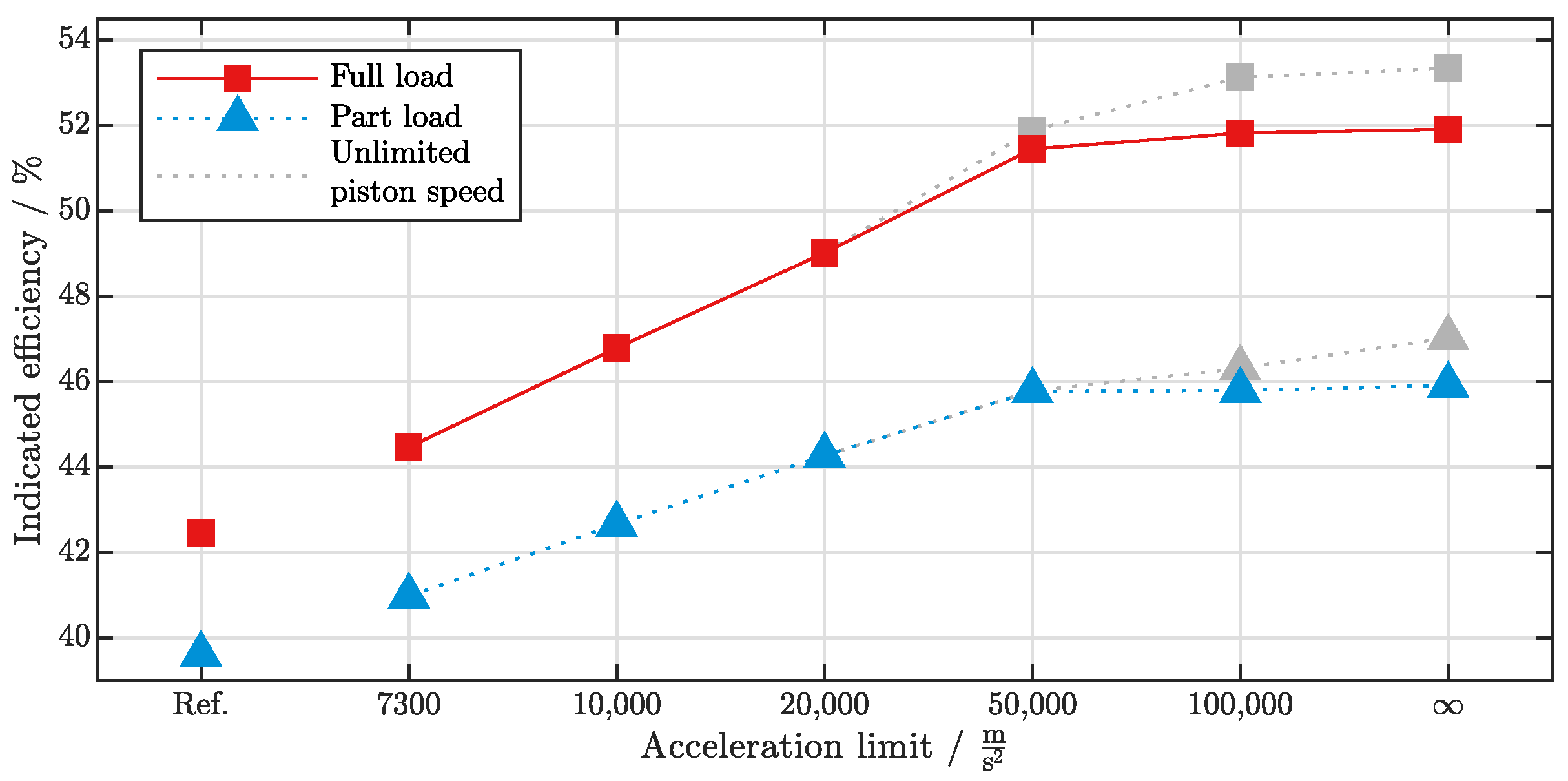
It can be observed that the optimized piston trajectories lead to a significantly higher power output, as shown in Figure 9. While this is partly due to an increase of fresh air mass at intake closing, it is mainly the result of a significantly higher efficiency, as shown in Figure 10. The deep expansion of the working gas in the power stroke, the minimization of pumping losses during gas exchange, the high heat release rates and therefore the resulting short burn durations, and the reduction of wall heat losses were identified as the main reasons for the increase in efficiency. In Figure 9 and Figure 10, it can be observed that the maximum piston velocity of 44 m/s becomes the limiting boundary condition for the high acceleration cases. While the full load cases with an acceleration limit of 50,000 m / s 2 or higher are affected by the piston velocity limit, in part load, this only applies to cases of 100,000 m / s 2 and above due to the relatively smaller piston displacements.

3.2.1. Pumping Losses

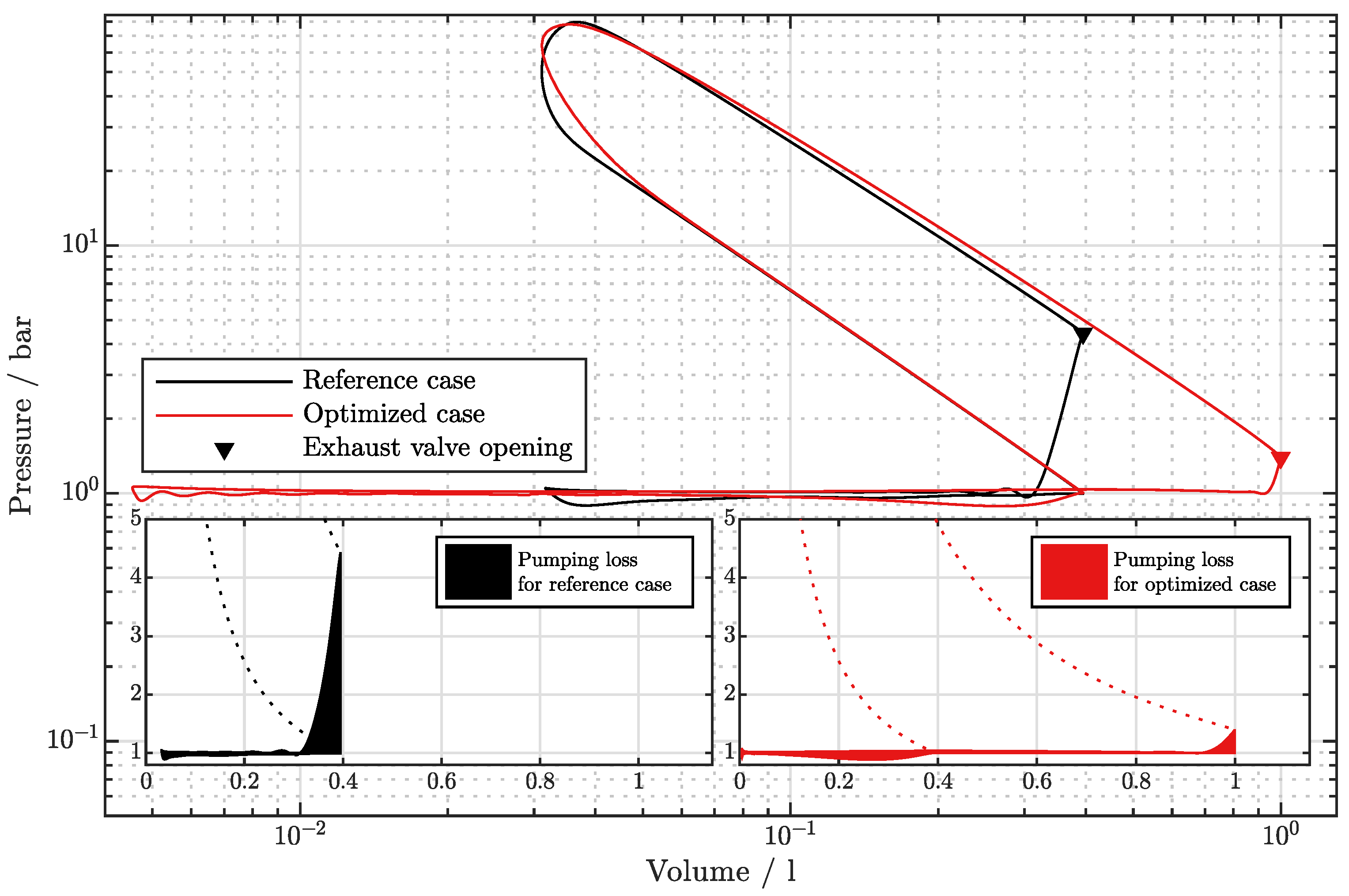
In order to measure the pumping losses correctly, the volume work of the piston during the gas exchange phase was determined. For this calculation, an ambient pressure of 1 bar was assumed on the other side of the piston and thus only the pressure difference from one side of the piston to the other was considered for the integral p d V . This is necessary to correctly represent the pumping losses for a piston trajectory with different displacements within one working cycle. The integral areas which represent the pumping losses during the gas exchange phase are marked for both reference and optimized piston trajectory individually in Figure 11. This allows for identifying the major difference between the cases. Although the enclosed area of the gas exchange phase of the new concept after the initial pressure drop, which follows exhaust valve opening, is comparable in size to that of the reference case, the integral of the p–V curve during this initial pressure drop, and thus the time period from the exhaust valve opening until ambient pressure is reached, is much larger in the reference case. As the working gas in the conventional crank drive does not expand to 1 bar, increased work must be done to expel the gas. This is also partially due to the simulation setup of the valves, which only begins to open at the start of a new phase and not earlier. Consequently, the slow opening of the exhaust valve might contribute to the observed effect. Accordingly, the pumping losses are lower in the optimized concepts. Moreover, the pumping losses in Figure 8 are normalized with respect to the indicated power output of the cylinder and, since the power output increases for the optimized cases (Figure 9), this further reduces the relative share of pumping losses.

3.2.2. Heat Release

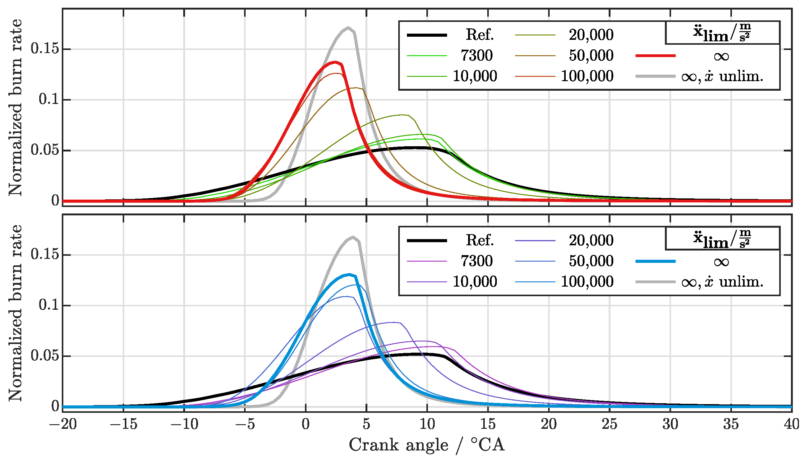
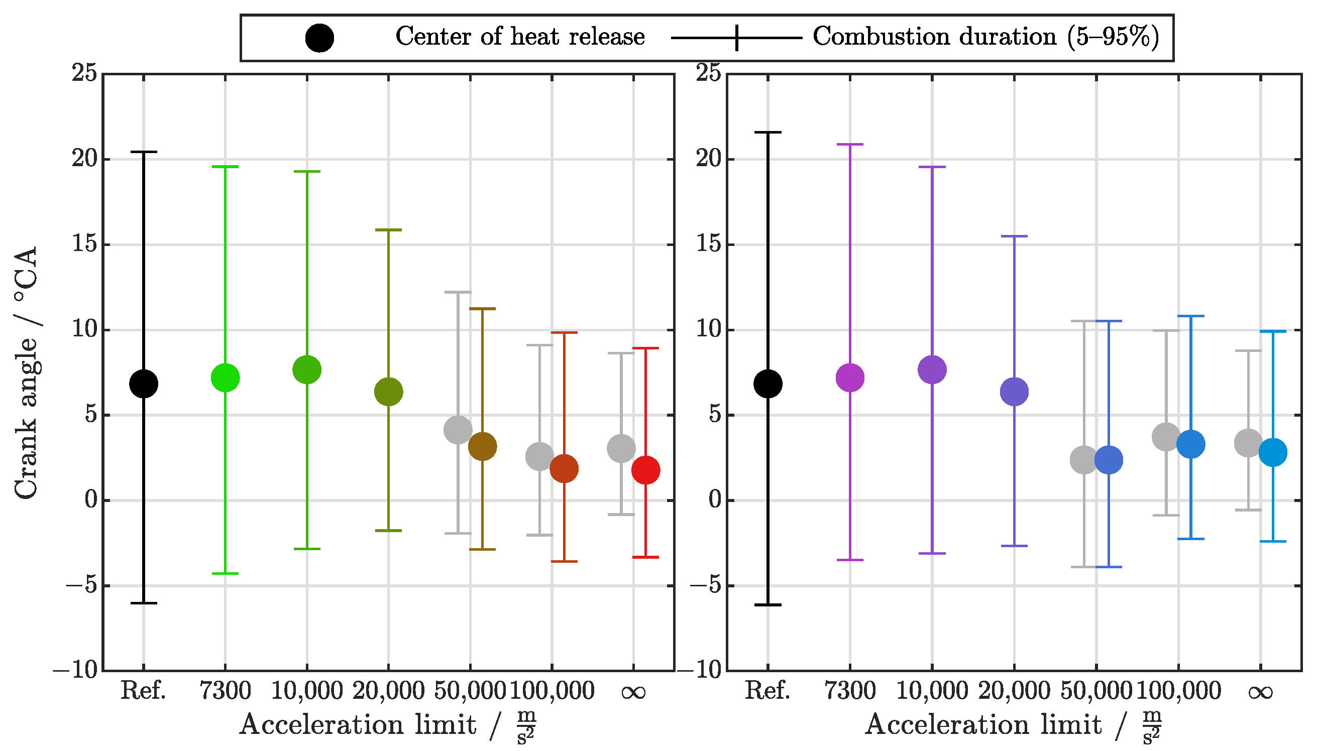
In general, a short heat release is advantageous for piston-based internal combustion engines in terms of efficiency. In Figure 12 and Figure 13, a clear trend of shorter burn durations with increasing piston acceleration limit can be observed. Even though the burn durations stagnate for high piston acceleration limits (Figure 13) due to the piston velocity limit being the main constraint in these cases, the results without the piston velocity limit continue this trend. It can be concluded that the optimization process leads to significantly shorter burn durations with high burn rates. This can be explained by the dependency of the burn rate on the turbulent flame speed, which is in turn highly dependent on the piston motion, as described in Equations (9)–(14). Consequently, it can be argued that the optimization favored cases with high piston velocities during the compression and expansion phases to generate turbulent kinetic energy that eventually leads to high burn rates. This relation is another reason for the observed short high pressure phase and long gas exchange in the optimized piston trajectory.
The results so far are evidence that a simple combustion model such as Wiebe based on observations from conventional engines is not sufficient to investigate the proposed research question in this study. Instead, the use of a physics-based combustion model that actually accounts for the effects of piston motion on the combustion process is essential.

3.2.3. Wall Heat Losses

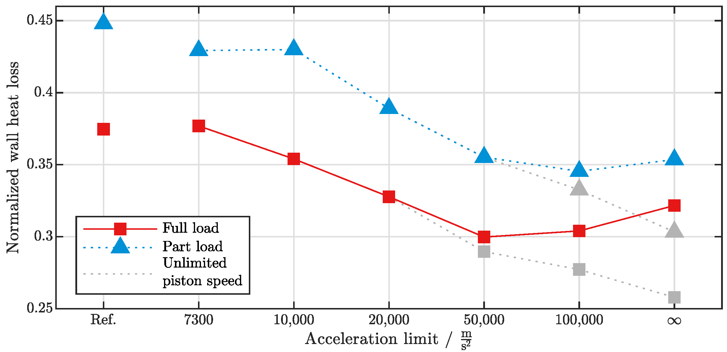
Figure 14 shows the wall heat losses normalized with the indicated work of one working cycle. It can be seen that the relative heat losses are at their highest for the reference case and decrease during optimization with increasing acceleration limits. Similar to other indicators so far, this trend stagnates at high piston acceleration limits due to the piston velocity becoming the limiting constraint, but continues when considering results without this boundary condition. Regarding wall heat losses, different phenomena can be considered, which partially cancel each other out. On the one hand, the generally larger surface area of the optimized piston trajectories with long expansion strokes is disadvantageous. Additionally, the exhaust phase, which lasts up to more than half of the entire working cycle, promotes wall heat losses. On the other hand, an opposing effect occurs when the time periods during which high temperatures can occur are significantly reduced in length as a result of the optimization. Thus, the short-duration compression and expansion phases result in an overall decrease in wall heat losses. The normalization of the wall heat losses with the power output of the cylinder which increases with higher acceleration limits also promotes this trend.

3.2.4. Trapped Air Mass

As mentioned above, the trapped fresh air mass at the start of compression is slightly higher in most optimized cases and increases with the acceleration limit up to around +5%. This contributes to the increased power output. The reason for this advantage can be found in the optimization of the top dead center position during gas exchange as shown in Figure 5, which resulted in a minimized clearance volume. This leads to an advantage in terms of residual gas for the optimized cases. Additionally, a slightly increased gas density due to differences in pressure and temperature at intake valve closure can be observed.

3.2.5. Piston Acceleration and Velocity

The piston accelerations as well as the piston velocities of the optimized trajectories are generally significantly higher. In case of an unlimited piston acceleration but limited piston velocity, a factor of 10 to the reference kinematics was observed. In the case of unlimited acceleration and unlimited velocity, this factor increases to 72. It is assumed that these levels of acceleration are probably not feasible for a hardware implementation of the concept, but the results were still included in this study to show the upper limit or potential of this approach. In the case where piston acceleration was limited to the maximum acceleration of the reference design (7300 m / s 2 ), the optimized piston trajectory still outperformed the conventional crank drive slightly in terms of efficiency. Going towards high acceleration limits, diminishing returns regarding efficiency can be observed. Nevertheless, the limit on acceleration for the piston trajectory has a huge impact on the expected performance improvement. Consequently, the ability to achieve high piston accelerations and speeds will be an important aspect in the design of new piston kinematics.
The highest piston accelerations occur in the vicinity of the high pressure top dead center, in other words at the end of compression and the beginning of expansion. The highest piston velocities occur in the same phases, on the way to and away from the top dead center. The optimization process showed that limits for both acceleration and velocity are important boundary conditions.

3.2.6. Part Load

When analyzing the simulation results for part load, very similar trends can be observed. The optimized piston trajectories for different acceleration limits show identical characteristics as in full load scenarios, as can be seen in Figure 4, Figure 5, Figure 6, Figure 7, Figure 8, Figure 9, Figure 10, Figure 11, Figure 12, Figure 13 and Figure 14. The indicated efficiencies are shifted towards a lower level, as expected in spark ignited engines, but still show a very similar trend during optimization as in the full load scenarios.

4. Conclusions

The investigation of the potential of an alternative piston trajectory for a spark ignited methane engine was successfully conducted using a physics-based cylinder and a combustion modeling approach. The genetic optimization algorithm was able to identify piston trajectory parameters for significantly increased indicated efficiencies up to 52% at full load in comparison to the reference case at 43%, and up to 46% at part load compared to the reference case at 40%. Different maximum piston acceleration limits have been analysed and were identified as an important boundary condition for the simulation. The increase in efficiency of the optimized piston trajectory can be explained by the following effects. A high expansion ratio after the combustion allows for extracting more energy from the working gas. It also lowers the cylinder pressure at an exhaust valve opening to almost ambient pressure, which, combined with relatively long time periods for gas exchange and the resulting low pressure gradients across the valves, reduces pumping losses. In contrast to that, the relatively short time periods for compression and expansion lead to reduced wall heat losses. Additionally, the extremely short compression phase generates high turbulent kinetic energy, which results in shorter and more efficient heat release of the combustion. In addition to the effects contributing to the efficiency gain, the power output of the cylinder was improved by an increase of trapped air mass at intake valve closing. The results also support the assumption for the methodology in that the modeling approach needs to represent the interaction of the thermodynamics with the piston motion in order to adequately investigate the performance of alternative piston trajectories.

Outlook

This study did not address the problem of how to achieve such a piston trajectory. However, since the optimization yielded a concrete result on how displacement, timings, and shape of the piston trajectory should be arranged, a clear objective for possible design studies is given.
On a critical note, despite the use of a physics-based prediction model for cylinder and combustion, the prediction accuracy is still uncertain due to the difference to conventional combustion engines on which the modeling approaches are based upon. A detailed 3D-CFD simulation of the optimal piston trajectory seems like a reasonable continuation of this study. Moreover, certain aspects of the simulation, especially towards boundary conditions, are still uncertain and present interesting questions for follow-up studies. For example, turbocharging of the engine has not been considered as the interaction of a turbocharger with this engine concept is unknown at this point. It is also unclear how direct injection would interact with the new concept. This study only assumed a homogeneous air fuel mixture which might be difficult to achieve in a DI scenario, regarding the short intake phase timings. Ideally, experimental investigations should be used to validate the predictions of the cylinder and combustion model. In this context, the interaction between the piston movement and the combustion speed would be of high interest.

Author Contributions

Conceptualization, C.B. and S.K.; methodology, C.B. and S.K.; software, S.K.; validation, S.K.; formal analysis, C.B. and S.K.; investigation, C.B. and S.K.; data curation, S.K.; writing—original draft preparation, C.B.; writing—review and editing, S.K.; visualization, S.K.; supervision, C.B.; project administration, C.B. All authors have read and agreed to the published version of the manuscript.

Funding

This research received no external funding.

Data Availability Statement

The results from the numerical simulation of all cases are available at [http://dx.doi.org/10.13140/RG.2.2.19152.38403 (accessed on 30 August 2022)]. The file includes time resolved raw data for the cylinder gas state and various mass flows.

Acknowledgments

Preliminary simulations to this study have been done by Rui Zhan as part of his Master’s Thesis.

Conflicts of Interest

The authors declare no conflict of interest.

Abbreviations

The following abbreviations are used in this manuscript:
ACCActive combustion chamber
CACrank angle
BDCBottom dead center
DIDirect injection
GTGamma technologies
ICEInternal combustion engine
NASANational Aeronautics and Space Administration
PCPersonal computer
TDCTop dead center
VCRVariable compression ratio

Appendix A

The parameters of all optimized piston trajectories for full and part load operation and different piston acceleration limits can be found in Table A1.
Table A1. Parameter for optimized trajectories according to Figure 2.
Full LoadPart Load
p 2 mbar1000583
x ¨ max m / s 2 Ref.730010,00020,00050,000100,000730010,00020,00050,000100,000
φ 3 °CA0.00.00.00.00.00.00.00.00.00.00.00.00.0
φ 4 °CA180.0186.6179.3181.5152.8156.8184.6191.4179.5181.5150.3152.6157.3
φ 1 °CA360.0410.7411.8399.7425.8447.0483.4374.9400.7395.4461.2463.7477.3
φ 2 °CA540.0573.8594.0628.7659.5662.0668.2568.6582.6625.7651.0653.9667.1
l 3 °CA180.0186.6179.3181.5152.8156.8184.6191.4179.5181.5150.3152.6157.3
l 4 °CA180.0224.1232.5218.2273.0290.2298.8183.5221.2213.9310.9311.1320.0
l 1 °CA180.0163.1182.3229.1233.7214.9184.8193.7181.9230.3189.8190.2189.8
l 2 °CA180.0146.2126.091.360.558.051.8151.4137.494.369.066.152.9
s 3 mm5.85.85.85.85.85.85.85.85.85.85.85.85.8
s 4 mm85.896.2119.4146.1195.6218.5218.795.4117.1136.5156.8156.7162.3
s 1 mm6.03.60.70.00.10.00.00.00.00.00.00.00.0
s 2 mm85.885.885.885.885.885.885.885.885.885.885.885.885.8
T 31 °CA171.9178.0176.2167.688.353.158.2183.9172.9149.983.584.378.0
T 22 °CA171.9185.1155.389.960.653.541.4170.0147.093.069.635.830.4
T 41 °CA239.4449.2504.7490.1463.4433.1434.2295.5445.1370.9447.8461.3441.7
T 32 °CA239.4259.1274.7392.1245.5220.9329.3303.7272.9391.5312.6322.3330.3
T 11 °CA171.9218.2316.1562.1597.3577.4451.4307.3317.9544.2398.4427.1417.1
T 42 °CA171.9222.0259.9273.0299.2297.0300.7218.6272.2266.2312.4313.7331.2
T 21 °CA239.4185.6160.192.569.065.040.2177.2186.0107.1110.4111.054.1
T 12 °CA239.4175.3234.5255.6259.0270.1254.4247.1250.2272.1257.5260.6256.0

References

  1. Mozurkewich, M.; Berry, R.S. Optimal paths for thermodynamic systems: The ideal Otto cycle. J. Appl. Phys. 1982, 53, 34–42. [Google Scholar] [CrossRef]
  2. Huleihil, M.; Andresen, B. Optimal piston trajectories for adiabatic processes in the presence of friction. J. Appl. Phys. 2006, 100, 114914. [Google Scholar] [CrossRef] [Green Version]
  3. Atkinson, J. Gas Engine. Patent US367496. 1887. Available online: https://patentimages.storage.googleapis.com/f0/d5/eb/c4fc0749bb82b2/US367496.pdf (accessed on 30 August 2022).
  4. Merker, G.P.; Teichmann, R. Grundlagen Verbrennungsmotoren, 7th ed.; Springer Vieweg: Wiesbaden, Germany, 2014; pp. 119–121. [Google Scholar] [CrossRef]
  5. Ge, Y.; Chen, L.; Sun, F. Optimal path of piston motion of irreversible Otto cycle for minimum entropy generation with radiative heat transfer law. J. Energy Inst. 2012, 85, 140–149. [Google Scholar] [CrossRef]
  6. Lin, J.; Chang, S.; Xu, Z. Optimal motion trajectory for the four-stroke free-piston engine with irreversible Miller cycle via a Gauss pseudospectral method. J. Non-Equilib. Thermodyn. 2008, 39, 159–172. [Google Scholar] [CrossRef]
  7. Xu, J.; Yuan, C.; He, Y.; Wang, R. An optimization of free-piston engine generator combustion using variable piston motion. Adv. Mech. Eng. 2017, 9, 1–10. [Google Scholar] [CrossRef]
  8. Zhang, C.; Li, K.; Sun, Z. Modeling of piston trajectory-based HCCI combustion enabled by a free piston engine. Appl. Energy 2015, 139, 313–326. [Google Scholar] [CrossRef]
  9. Roberts, M. Benefits and Challenges of Variable Compression Ratio (VCR); SAE Technical Paper 2003-01-0398; SAE International: Warrendale, PA, USA, 2003. [Google Scholar]
  10. Asthana, S.; Bansal, S.; Jaggi, S.; Kumar, N. A Comparative Study of Recent Advancements in the Field of Variable Compression Ratio Engine Technology; SAE Technical Paper 2016-01-0669; SAE International: Warrendale, PA, USA, 2016. [Google Scholar] [CrossRef]
  11. Dabrowski, A.; Glogowski, M.; Kubiak, P. Improving the efficiency of four-stroke engine with use of the pneumatic energy accumulator—Simulations and examination. Int. J. Automot. Technol. 2016, 17, 581–590. [Google Scholar] [CrossRef]
  12. Deb, K.; Jain, H. An Evolutionary Many-Objective Optimization Algorithm Using Reference-Point-Based Nondominated Sorting Approach, Part I: Solving Problems With Box Constraints. IEEE Trans. Evol. Comput. 2014, 18, 577–601. [Google Scholar] [CrossRef]
  13. Gamma Technologies LLC. GT-Suite Flow Theory Manual Version 2020; Gamma Technologies LLC: Westmont, IL, USA, 2020. [Google Scholar]
  14. Gamma Technologies LLC. GT-Suite Engine Performance Application Manual Version 2020; Gamma Technologies LLC: Westmont, IL, USA, 2020. [Google Scholar]
  15. McBride, B.J.; Gordon, S.; Reno, M.A. Coefficients for Calculating Thermodynamic and Transport Properties of Individual Species. NASA Technical Memorandum; 1993. Available online: https://ntrs.nasa.gov/citations/19940013151 (accessed on 30 August 2022).
  16. Woschni, G. A Universally Applicable Equation for the Instantaneous Heat Transfer Coefficient in the Internal Combustion Engine. SAE Trans. 1968, 76, 3065–3083. [Google Scholar]
  17. Heywood, J.B. Internal Combustion Engine Fundamentals; McGraw-Hill: New York, NY, USA, 1988; ISBN 0-07-028637-X. [Google Scholar]
  18. Gamma Technologies LLC. GT-Suite 2020 Help Menue (Reference Manual—Flow—Engine Reference Template—Si-Turbulent Flame); Gamma Technologies LLC: Westmont, IL, USA, 2020. [Google Scholar]
  19. Krebs, S.; Biet, C. Predictive model of a premixed, lean hydrogen combustion for internal combustion engines. Transp. Eng. 2021, 5, 100086. [Google Scholar] [CrossRef]
  20. Pipenbrinck, N. Hermite Curve Interpolation. Available online: https://www.cubic.org/docs/hermite.htm (accessed on 30 August 2022).
  21. Worret, R. Zylinderdruckbasierte Detektion und Simulation der Klopfgrenze Mit Einem Verbesserten Thermodynamischen Ansatz. Ph.D. Thesis, University of Karlsruhe, Karlsruhe, Germany, 2002. [Google Scholar]
  22. The Fastest Production Audi Ever: The New AUDI R8. AUDI AG Product and Technology Communications. 2015. Available online: https://audimediacenter-a.akamaihd.net/system/production/uploaded_files/366/file/d9f72d4b92b263acccf5dcec5fce345deeb5295b/eBasisinformation_R8.pdf?1484227032 (accessed on 22 September 2022).
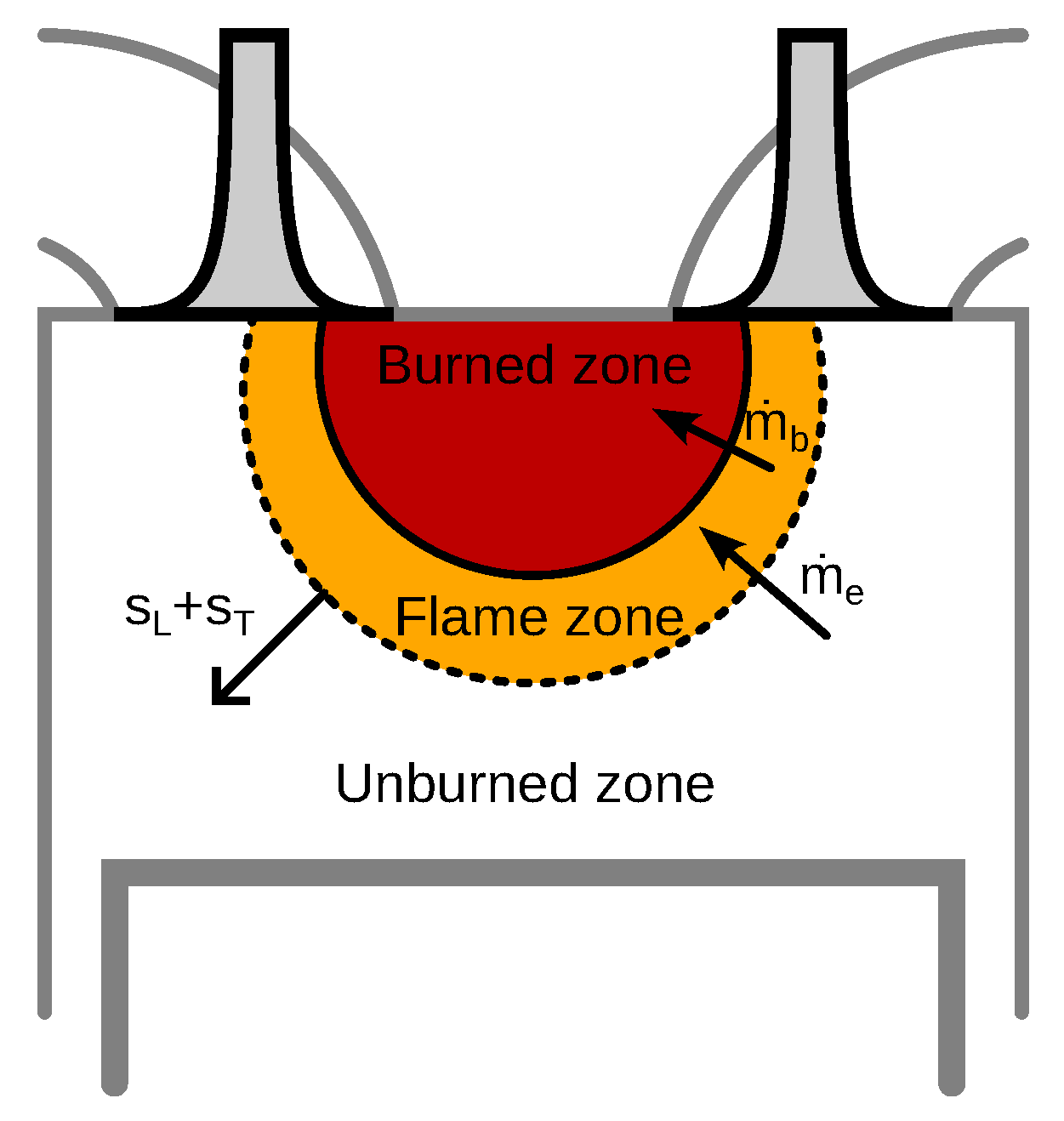
Figure 1. Visualization of the phenomenological combustion model SI-turb.
Thermo 02 00024 g001
Figure 2. Parameters of the 4 cubic Hermite spline functions that combine to the adjustable piston trajectory.
Thermo 02 00024 g002
Figure 3. Illustration of the valve timing set up. Valve lifts are adjusted according to the stroke length based on the valve lift curve of the reference engine.
Thermo 02 00024 g003
Figure 4. Optimized piston trajectories at full (top) and part (bottom) load operation for different maximum piston acceleration limits.
Thermo 02 00024 g004
Figure 5. Evolution of the piston dead center positions for full and part load operation as a function of a maximum piston acceleration limit.
Thermo 02 00024 g005
Figure 6. Pressure over volume diagram comparing the full and part load operation of the optimized piston trajectories without acceleration or velocity limit compared to the reference case.
Thermo 02 00024 g006
Figure 7. Evolution of the phase lengths for full and part load operation as a function of a maximum piston acceleration limit.
Thermo 02 00024 g007
Figure 8. Evolution of the normalized pumping losses for full and part load operation as a function of the maximum piston acceleration limit.
Thermo 02 00024 g008
Figure 9. Evolution of the indicated power output of the cylinder for full and part load operation as a function of the maximum piston acceleration limit.
Thermo 02 00024 g009
Figure 10. Evolution of the indicated efficiency for full and part load operation as a function of maximum piston acceleration limit.
Thermo 02 00024 g010
Figure 11. Pressure over volume diagram comparing pumping losses between the reference case and the optimized piston trajectory without acceleration limit.
Thermo 02 00024 g011
Figure 12. Heat release rates for the optimized piston trajectories at full (top) and part (bottom) load operation for different maximum piston acceleration limits.
Thermo 02 00024 g012
Figure 13. Timings for 5%, 50% and 95% of combusted fuel for the optimized piston trajectories at full (left) and part (right) load operation for different maximum piston acceleration limits.
Thermo 02 00024 g013
Figure 14. Evolution of the normalized wall heat losses for full and part load operation as a function of maximum piston acceleration limit.
Thermo 02 00024 g014
Table 1. Comparison of combustion parameters between experimental measurement and simulation for model validation.
IngnitionCenter of
Heat
Release
Burn Duration
(10–90%)
Indicated Mean
Effective
Pressure
°CA°CA°CA°CA
Full loadexperiment11.34719.68224.28210.5448
simulation11.30223.6211.542
Part loadexperiment26.0510.57721.864.26
simulation10.5821.936.28
Table 2. Values for piston acceleration, power and efficiency for comparing the reference case to the optimization results.
ReferenceOptimized
Piston acc. limit m / s 2 730010,00020,00050,000100,000
Max. piston acc. m / s 2 72557288999819,96649,90665,85969,479
Max. piston speed m / s 15.219.925.3435.7743.9843.9443.96
Indicated powerkW13.514.215.816.717.517.817.8
Indicated efficiency%42.544.546.849.051.451.851.9
Publisher’s Note: MDPI stays neutral with regard to jurisdictional claims in published maps and institutional affiliations.