Abstract
The study of heat transfer in ground heat exchangers (GHEs) considering the fluid advection inside the pipes; the heat transfer between the fluid and the ground through the grout material; and the thermal interaction between GHEs is a challenging task. The present paper presents a new semi-analytical method that takes into account the aforementioned effects to consider both the short- to long-term effects of GHEs. The heat transfer between the fluid and grout was studied by a transient multipole expansion considering time-dependent fluid temperatures and an advection model for the pipes obtained from an energy balance on the heat carrier fluid. Thermal interactions were analyzed using an equivalent borehole method while penalizing the transient multipole expansion to include thermal interaction effects. Validation of the short-term predictions was performed by comparing the proposed model to experimental data found in the literature and to an FEA model. The proposed model was then compared with a FEA model in long-term simulations of a geothermal field comprised of 24 GHEs for multi-annual simulation. The method resulted in substantial reduction in computational time while preserving good accuracy when compared with the FEA model.
1. Introduction
One of the renewable energy sources that has been growing steadily worldwide in the last decade is geothermal energy [1]. Ground coupled heat pump (GCHP) systems are among the most efficient geothermal systems used for heating and cooling buildings [2]. GCHP systems consist of one (or several) heat pump that supplies heating or cooling to a building through the ground via ground heat exchangers (GHEs). GHEs are a core part of the GCHP system and consist of boreholes containing one or several U-tubes through which a heat-carrier fluid flows, and it is backfilled with grout material. In each of the GCHP design, control and operation phases, it is necessary to understand the heat transfer process between not only one but several GHEs. For instance, meeting the energy demands of a building requires that the GHEs are adequately sized so that returning fluid temperatures remain within the operating bounds of the GCHP system. Fluid temperature variations can be predicted from a model of the heat transfer between the fluid and the soil given ground thermal loads, accounting for possible thermal interactions between GHEs located in close proximity. Thus, improvements in the accuracy of heat transfer models lead to improvements in the accuracy of the design of GHEs.
Heat transfer phenomena are studied on different time scales, from short-term to long-term effects. Short-term effects are due to the flow of the fluid inside the U-tube coupled with the heat conduction between the pipes and the grout. At this time scale that ranges from minutes to a few hours, the thermal capacity of the grout decreases the rate of heat propagation between the fluid and the soil, and not taking this phenomenon into account can lead to an overestimation of the fluid temperatures [3]. The short-term effects end when quasi-steady conditions are reached inside the GHE, i.e., when temperature gradients are constant under a constant ground load. Long-term effects, spanning days to hundreds of years, include thermal interactions between boreholes and axial heat transfer effects due to interaction with the surface and the ground below the GHEs. It is necessary to consider both the short- and long-term effects to properly design a field of GHEs and ensure proper operation of a GCHP system throughout its life cycle [4].
Long-term heat transfer outside GHEs is studied both analytically and numerically. The well-known classical analytical solutions correspond to the infinite line source (ILS) [5] and the cylindrical heat source (CHS) [6]. Analytical solutions can be superimposed in time and space to consider variable ground loads and thermal interactions between GHEs. An important limitation of these classical solutions is that they cannot represent axial effects. Eskilson [7] solved the tridimensional heat transfer problem using a finite difference method. GHEs were represented as hollow cylinders with uniform and equal—but time-varying—temperatures. The model was used to produce dimensionless unit-step response functions, called g-functions, that give the relation between the borehole wall temperature and the heat extraction rates. Like analytical solutions, g-functions can be superimposed on time to consider variable ground loads. The g-function is defined by:
where is the borehole wall temperature, is the undisturbed ground temperature, is the thermal conductivity, Q is the total heat extraction rate into the borefield, L is the borehole length and is the number of boreholes.
Eskilson [7] proposed the analytical finite line source (FLS) to estimate the g-function of a single borehole. The FLS was later superimposed on space to evaluate g-functions of fields of GHEs [8,9,10]. For larger fields, the FLS can lead to important errors in the g-functions due to a mismatch of the boundary conditions at the borehole wall between the FLS (uniform and equal heat extraction rates) and the g-functions (uniform and equal temperatures). These errors can be eliminated by discretizing the GHEs to consider the variation in heat extraction rates along the lengths of GHEs and their variations in time to reproduce the uniform temperature condition of Eskilson [11,12]. In reality, neither the heat extraction rates nor the borehole wall temperatures are uniform along the lengths of the boreholes, since heat transfer is driven by the temperature difference between the fluid and the borehole wall. A more proper boundary condition is that of an imposed inlet fluid temperature, considering the internal thermal resistances of the boreholes and the piping connections between them [13,14,15]. The g-functions—and thus the returning fluid temperatures—are dependent on the borehole thermal resistances and the fluid mass flow rate. Spatial and temporal superposition of the FLS solution are also used for network-based models that study, at every time step, the complete distribution of the borehole wall temperatures considering the hydraulic connections between GHEs [16,17,18]. The computational requirements of analytical models increase as the complexity of the boundary condition increases. In the case of the imposed inlet fluid temperature, a system of equations must be built and solved to evaluate heat extraction rate profiles and borehole wall temperature profiles along all GHEs in the field. Prieto and Cimmino [19] proposed a method to limit the sizes of the systems of equations by forming groups of similarly behaving boreholes and modeling each of these groups using a single equivalent borehole. This results in an efficient and robust method that allows the study of geothermal fields composed of thousands of GHEs.
Knowing that internal configurations have a direct impact on the thermal interactions among boreholes and the long-term responses of GHEs, some researchers have coupled short-terms models with long-term models to conduct simulations. Yavuzturk and Spitler [20] were the first to introduce an extension of the g-function considering short time steps while including thermal capacity inside the GHE but disregarding the thermal capacity in the fluid. Later, Xu and Spitler [21], based on the work from Yavuzturk and Spitler [20], developed a one-dimensional model using a finite volume method, where the fluid is considered as an annular volume within the pipe, along with an equivalent thermal capacity. Brussieux and Bernier [22] coupled a finite volume method for the interior of a GHE with the CHS solution for the exterior of a GHE, resulting in the definition of -functions for short-term effects. Claesson and Javed [8] coupled an equivalent geometry model for the interior of the GHE [23] and used the FLS solution to study thermal interactions between the GHEs. Li et al. [24] used the analytical infinite composite-medium line source (ICMLS) [25] to model the insides of GHEs and the g-functions to account for thermal interactions among GHEs. In all aforementioned cases, despite the coupling of the short- to long-term solutions, the methods do not consider the advection inside the pipes and consider that all the GHEs have the same borehole wall temperature, which is not the case, as demonstrated by Cimmino [13] and Monzó et al. [26]. Pasquier and Marcotte [27] developed a response model based on a thermal resistance and capacitances (TRC) method to generate the thermal response factor of a GHE and estimate the fluid temperatures. Laferrière et al. [28] considered the axially-discretized thermal resistances and capacitances (TRC) model of Bauer et al. [29] coupled to an advection model and to g-functions, using a single uniform temperature at the wall of a GHE that represents the entire bore field. Recently, Alaie et al. [30] developed a solution based on the TRC method proposed by Minaei and Maerefat [31] and the segment-to-segment response factors proposed by Cimmino and Bernier [12] to consider both short- to long-term responses. As opposed to the earlier methods, their method does not consider that borehole wall temperatures are the same for all GHEs and thus achieves better representations of the distribution of heat extraction rates and temperatures within the field of GHEs. Additionally, there exist mesh-dependent approaches, such as those of Al-Khoury and Bonnier [32] and Diersch et al. [33,34], which are able to impose many boundary conditions and use many arrangements of GHEs; however, these methods are computationally demanding when considering multiple boreholes and including short- to long-term effects.
Axially-discretized methods become computationally demanding when very large fields of GHEs are considered. Thus, there is a need for accurate and computationally-efficient models that consider short-term effects, including advection in the pipes, and are able to simulate not only a single GHE but thousands. Coupled short- and long-term models can also benefit from recent advancements in short-term models, such as the transient multipole methods. Rivero and Hermanns [35] proposed a solution by means of matched asymptotic expansion to evaluate the thermal resistances in a spectral domain. Prieto and Cimmino [36] developed a transient multipole expansion to describe the variations in fluid, pipe and borehole wall temperatures in the time domain. In both approaches, the fluid thermal capacity and the advection of the fluid through the pipes are not taken into account.
This paper introduces a new methodology to study the transient heat transfer for both the interiors and exteriors of GHEs, considering fluid flow inside the pipes, fluid-to-soil heat conduction via grout, thermal interactions among GHEs and axial effects. The equivalent borehole method of Prieto and Cimmino [19] is used to model the exteriors of the GHEs, including thermal interactions between GHEs. The transient multipole method of Prieto and Cimmino [36] is used to model the interiors of the GHEs, including temperature penalization to account for thermal interactions. A finite difference model of fluid advection inside the pipes is used to consider the axial distributions of fluid temperatures and heat extraction rates. The model was first compared against the sandbox test of Beier et al. [37] to validate the accuracy of the short-term response, and then against a multi-annual simulation of a thermally interacting field of 24 boreholes using a finite element analysis (FEA) solver based on Diersch et al. [33,34] to show that the method is able to include both short-term effects and thermal interactions between boreholes for larger periods of time.
2. Mathematical Model
Figure 1 shows a borefield composed of vertical GHEs, i and j, of the same dimensions and separated by a horizontal distance . All GHEs are connected in parallel and are fed a heat carrier fluid at the same inlet temperature and mass flow rate. Each GHE is composed of a single U-tube (although the presented model can be extended to any U-tube configuration). The geometrical parameters are the same for each GHE and include: the borehole length L, the buried depth D, the borehole radius , the pipe outer radius with wall thickness and the U-tube shank spacing e. The thermal properties are considered homogeneous, isotropic and constant. and are the thermal conductivities (k) of the grout (b) and soil (s), respectively. and are the thermal diffusivities () of the grout and soil, respectively.
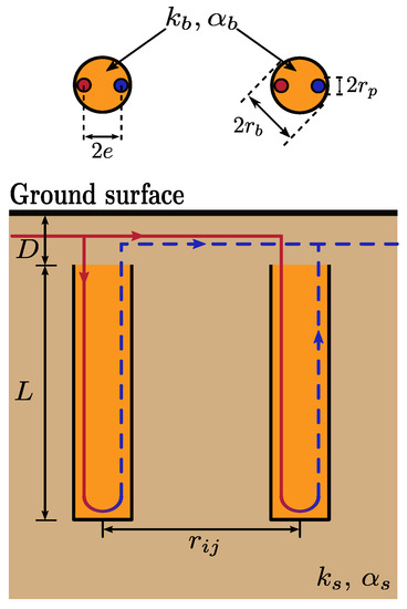
Figure 1.
Field of 2 vertical boreholes of equal dimensions.
The horizontal conduction heat transfer inside the GHE is studied in a transient state using the transient multipole expansion method developed by Prieto and Cimmino [36]. This solution is extended to consider time-dependent fluid temperatures inside the U-tube by means of a coefficient updating scheme. The radial and axial heat conduction in the soil around GHEs, and the interactions between GHEs, are modeled with the FLS solution by considering thermal interactions between equivalent boreholes as proposed by Prieto and Cimmino [19]. The transient multipole method is coupled to the FLS solution to consider both of the short- and long-term effects around GHEs, and to a discretized finite difference model of the advection heat transfer process inside the U-tubes. The proposed model was compared to a finite element analysis (FEA) model, based on the methodology developed by Diersch et al. [33,34], with specific modifications to ensure solution stability, as will be discussed in Section 2.4.
2.1. 2D Transient Heat Transfer with Time-Dependent Fluid Temperatures
2.1.1. Transient Multipole Expansion
The short-term transient heat transfer problem in the local vicinity of a GHE j is modeled in 2D for a horizontal cross-section of the GHE, considering conduction in the grout () and the soil (). The heat transfer problem relies on the transformation of coordinates based on geometrical characteristics of the GHE; thus, a point in the 2D-polar space could be expressed at any center with translated coordinates , as shown in Figure 2. The combination of the convection from the fluid to the pipe inner surfaces and the conduction across the pipes is represented as Robin boundary conditions at the pipe outer surfaces (at a radius from a pipe axis). The thermal capacitance of the pipes is neglected.
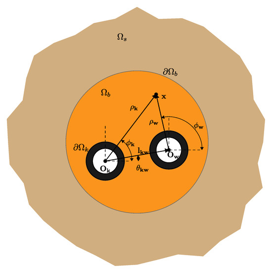
Figure 2.
Computational domain of a GHE.
The temperature at a far-field boundary (at ) is considered constant and equal to the undisturbed ground temperature . For constant fluid temperatures inside N arbitrary positioned pipes and a uniform initial temperature in the grout and soil (i.e., in ), the transient heat transfer problem in radial coordinates is given by:
where is equal to the thermal diffusivity in the grout or soil ( and ) for indices , respectively; is the dimensionless fluid to outer pipe wall thermal resistance of pipe k; and is the fluid to outer pipe wall thermal resistance. is the fluid temperature at pipe k in a GHE j.
Following the method of Prieto and Cimmino [36], the transient heat transfer problem with non-homogeneous boundary conditions for is separated into two sub-problems: a transient heat transfer problem with homogeneous boundary conditions for , and a steady-state heat transfer problem with non-homogeneous conditions for . The complete solution is then given by superposition, with .
The homogeneous transient heat transfer problem is then:
The non-homogeneous steady-state heat transfer problem is given by:
The solution to the homogeneous transient heat transfer problem is obtained by means of separation of variables and expressed as a Fourier–Bessel expansion:
where is the w-eigenvalue associated with the separation of variables sub-problem for each domain d satisfying the continuity condition for a GHE j. are the quasi-orthogonal eigenfunctions related to the eigenvalue for each domain d in GHE j.
For the grout domain (), containing N arbitrarily positioned pipes, the quasi-orthogonal eigenfunction is expressed as follows:
and for the soil domain ():
where J and are Bessel and Hankel functions of the first kind; M is the number of terms of the multipole expansion; and , and are coefficients introduced to match the boundary conditions in Equations (3b)–(3e). are the Fourier–Bessel coefficients satisfying the initial condition (Equation (3f)) and are given by:
The solution to the non-homogeneous steady-state heat transfer problem defined in Equation (4) is treated as a multipole expansion for a T-complete basis. For the grout domain (), containing N arbitrarily positioned pipes, the solution is expressed as follows:
and for the soil domain ():
where is the minimum external radius of the pipes; is an arbitrary radius and is equal to ; and h is the number of terms in the complete expansion. Similarly to multipole expansion for the quasi-orthogonal eigenfunctions, terms , , , , and are determined by matching the boundary conditions in Equations (4b)–(4e). According to Prieto and Cimmino [36], the values of and , and are set to 0. Here, the authors note that, for the present method, keeping all terms expressed in Equation (10) stabilizes the integration in Equation (8), where terms and , are small when matching the far-field boundary with m. For more details concerning the evaluation of eigenvalues and coefficients to match the boundary conditions in both problems, readers are referred to Prieto and Cimmino [36].
2.1.2. Time-Dependent Fluid Temperatures
Prieto and Cimmino [36] introduced a coefficient updating scheme to consider the variations in fluid temperatures as step-wise variations at each time step n for every (where ). The initial temperatures in Equations (3f) and (8) are replaced by the temperature at the end of the latest time step as follows:
Therefore, the Fourier–Bessel coefficients are calculated using this scheme at each time step:
with
where is the solution of the steady-state problem considering the fluid temperatures at the n-th time step, and in a GHE j. Note that when Equations (11) are substituted into Equation (8), the sums in Equations (11) disappear, since the integrals with terms are 0 if due to the quasi-orthogonal condition in the whole domain .
As written, Equation (12) is computationally intensive, since at every time step the integrals expressed in Equation (13) must be calculated. However, using the linearity in the steady-state problem described by Equation (4), it is possible to decompose the temperature field as a weighted sum of the fluid temperatures at each pipe. The temperature field can be expressed as N subproblems, and subtracting from the global problem yields:
where are the weighting functions in the domain d for a subproblem l in a GHE j:
where is the Kronecker delta function which takes the value 1 if and 0 otherwise. Equations (14) and (15) constitute a decomposition on N subproblems representing a unitary pulse at each pipe for each ; therefore, is time independent. Solving follows the same multipole expansion structure shown in Section 2.1.1.
The terms are independent of the fluid temperatures and thereby only need to be evaluated once at the initialization of a simulation.
2.2. Thermal Interactions between Ground Heat Exchangers
A temperature penalization approach is proposed to extend the transient multipole model to 3D, including axial heat transfer and thermal interactions between boreholes. Following the method of Cimmino and Bernier [12], each GHE is divided into segments (totaling layers), and each segment is modeled as a line heat source with a uniform heat extraction rate positioned at the axis of the GHE segment. Figure 3 shows a uniform discretization for two boreholes i and j separated with a distance . Each segment u has a length . The finite line source (FLS) solution can then be superimposed to evaluate a penalty on the temperatures predicted by the transient multipole method. Additionally, the equivalent borehole method of Prieto and Cimmino [19] is used to simplify the thermal interaction problem and obtain a computationally-efficient simulation model of the bore field by only requiring the simulation of a limited number of equivalent boreholes instead of the entire field of boreholes.
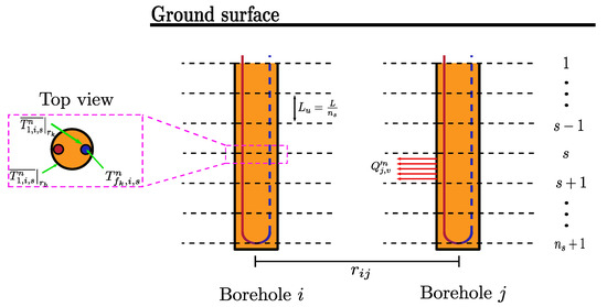
Figure 3.
() segments discretization of boreholes i and j.
2.2.1. Spatial and Temporal Superposition of the Finite Line Source Solution
The temperature drop at the borehole wall of a segment u of a borehole i at time can be evaluated from the spatial and temporal superposition of the analytical FLS solution:
where is the temperature drop at the wall of segment u of borehole i at time ; is the temperature at the wall of segment u of borehole i at time ; is the heat extraction rate per unit length of segment v of borehole j from time to ; and is the segment-to-segment thermal response factor for the borehole wall temperature change over segment u of borehole i caused by heat extraction from segment v of borehole j.
The segment-to-segment response factor is given by the FLS solution:
where is the radial distance between boreholes i and j (with ), is the error function and is the integral of the error function.
Recently, Prieto and Cimmino [19] proposed a methodology to account for thermal interactions among boreholes as interactions between equivalent boreholes sharing similar borehole wall temperatures and heat extraction rates. The field is divided into equivalent boreholes using a hierarchical aglomerative algorithm. Each equivalent borehole represents a group composed of boreholes. The temperature drop at the borehole wall of a segment u of an equivalent borehole at time is then:
where is the temperature drop at the wall of segment u of equivalent borehole at time ; is the heat extraction rate per unit length of segment v of equivalent borehole from time to ; and is the equivalent segment-to-segment response factor for the borehole wall temperature change over segment u of equivalent borehole caused by heat extraction from segment v of equivalent borehole .
The equivalent segment-to-segment response factor is given by the average segment-to-segment response factors for the borehole wall temperature change along segments u of all boreholes in group due to the heat extraction at all segments v of all boreholes in group :
To reduce the computation time involved in the Equation (21), a load aggregation scheme is employed and presented in Appendix A. This scheme is already implemented in the pygfunction library [38], which was used here both for the aggregation of loads (Equation (21)) and for the calculation of segment-to-segment response factors (Equation (22)).
2.2.2. Penalization of the Transient Multipole Solution
A penalization technique is proposed to couple the transient multipole method presented in Section 2.1 with the equivalent borehole method. The transient multipole method can be used to evaluate the borehole wall heat extraction rate on ground layers, and the equivalent borehole method can be used to evaluate the borehole wall temperature change over segments (see Figure 3). Thus, an interpolation scheme is introduced to evaluate the heat extraction rate over a segment u from the transient multipole solution of its two delimiting layers, s and (with ):
where is the heat extraction rate per unit borehole length of a segment u of equivalent borehole . Expressions for the temperature derivatives at the borehole wall are given in Appendix B.
The borehole wall temperature drop at a layer s is obtained from the borehole wall temperature drops at the two adjoining segments and u (with ):
where is the borehole wall temperature drop at a layer s of an equivalent borehole . For the top () and bottom () layers:
The penalization is applied to the transient multipole expansion solution for each layer s by introducing the difference between the temperature drop at borehole wall for an equivalent borehole and the temperature drop at the same layer s by means of the transient multipole expansion, and Equation (17):
where is the j-th Fourier–Bessel coefficient at time step for a layer s in an equivalent borehole , and are the eigenvalues related to a layer s in an equivalent borehole . Expressions for the average temperature at the borehole wall are given in Appendix B.
The complete solution by means of transient multipole expansion for a particular layer s in an equivalent borehole at time step in the grout and soil is then:
where are the weighting functions for a layer s in an equivalent borehole in domain d (i.e., grout and soil).
Although the complete solution in Equation (28) looks computationally intensive due to eigenvalues, eigenfunctions, integrals and weighting functions, in practical applications, all boreholes possess a uniform geometry along their length and across the field. These terms thus only need to be evaluated once at the initialization of the simulation, except for the Fourier–Bessel coefficients that depend on the layer and the time step. Another interesting thing in Equation (28) is that even though , and are considered constant, the undisturbed ground temperature could change at each equivalent borehole, enabling the inclusion of thermal gradients and layered solutions when the soil thermal properties are not isotropic.
2.3. Advection Inside the Pipes
The model described in Section 2.1.1 and Section 2.2 allows the evaluation of ground temperatures based on known fluid temperature profiles at each pipe k at every equivalent borehole . This model needs to be coupled to a model of advection inside the pipes to complete the simulation model and predict fluid and ground temperatures based on ground loads.
Assuming quasi-steady plug flow inside the pipes and neglecting heat conduction in the direction of flow (i.e., only considering heat convection between the fluid and the inner pipe wall), energy balances on a layer at downward-flowing pipe p and an upward-flowing pipe q are given by:
where z is the axial position along the pipe (positive in the downward direction); and are the fluid density and specific heat at constant pressure, respectively; and is the average mass flow rate in a U-tube containing pipes p and q for an equivalent borehole at the particular time step .
The fluid to outer pipe thermal resistance, , is given by the sum of the film resistance at the inner pipe wall and the conduction resistance across the pipe wall:
where is the Nusselt number, is the Reynolds number, is the Prandtl number and is the pipe thermal conductivity.
An implicit finite difference scheme is used to solve the problem. The GHE is discretized into layers, according to Figure 3. The discretized energy balance on a control volume delimited by two consecutive ground layers is given by:
The number of unknowns for the fluid temperatures per equivalent borehole, , at each time step in Equation (31), is equal to . A continuity condition is imposed at the bottom of the equivalent borehole:
where pipes but belong to the same U-tube.
The system of equations is completed by imposing the ground loads , for the complete borefield. In this case, boreholes are assumed to be connected in parallel:
where and are the inlet and outlet temperatures at time step n in the borefield and is the total mass flow rate, with the mass flow rate per borehole.
As the borefield is parallel-connected, the inlet temperature is the same for each equivalent borehole :
The outlet temperature of the borefield, , is obtained by mixing of the fluid at the outlet of all equivalent boreholes:
The problem is then complete, and it is possible to estimate the fluid temperatures at each equivalent borehole while imposing the heat extracted or rejected from the ground. An iterative scheme is used to solve the simulation model at each time step n:
- Calculate fluid temperatures, , using the pipe temperatures at the previous time step () as a first guess in Equation (31) with their boundary conditions and ground loads at time step n;
- Update the coefficients in Equation (27) using the fluid temperatures , heat transfer rates and average borehole wall temperatures calculated in steps (1) and (2);
- Recalculate according to Equation (28) using the new coefficients obtained in step (3);
- Compute the new fluid temperatures as in step (1) with the new pipe temperature calculated in step (4);
- Repeat from (2) if the difference of between the previous and current iterations is greater than C.
The method converges quickly, usually after two or three iterations. In this case, a linear system is solved with a guessed or updated value for ; thus, the unknowns in the system of equations for estimating the fluid temperatures are equal to . For the limiting case when the ground load is 0 W, the mass flow is set to 0 kg/s. Therefore, the solution of Equations (29) does not require solving a system of equations, since the term containing the derivative with respect to z is eliminated.
2.4. Finite Element Modeling
A reference finite element analysis (FEA) model was developed to validate the proposed method. Diersch et al. [33,34] developed a complete FEA model that includes the transient effects inside and outside GHEs and thermal interactions between them. This is an extension of the model previously proposed by Al-Khoury and Bonnier [32]. The same mathematical formalism is used in the present paper with some modifications.
The method was created on double-continuum finite element (i.e., one continuum media for the soil and one for the GHEs) space based on Galerkin discretization with 6-node prismatic elements for the 3D model. Each GHE is simulated as a line element surrounded by six nodes that virtually represent the borehole wall, located at a distance greater than , as presented in Diersch et al. [34]. Figure 4 shows the discretizations used for the two simulations used to validate the proposed semi-analytical methodology. First, the discretization shown in Figure 4a corresponds to a single borehole and was used for the comparison against experimental data. Then, Figure 4b shows the discretization for a borefield composed of 24 GHEs that was used in multi-annual simulations.
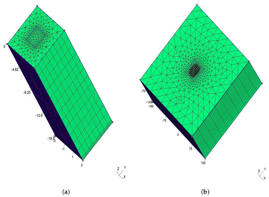
Figure 4.
Finite element discretization for model validation. (a) Mesh for Beier’s experiment. (b) Mesh for a borefield with 24 GHE.
For each line element, short-term effects were modeled using the TRC model developed by Bauer et al. [29,39]. The correction noted by Bauer et al. [39] and presented in FEFLOW white papers (Section 1.5.5) [40] was used when negative internal thermal resistances were present. Depending on the number of U-tubes, each node over the line element presents two pairs of temperatures: two for the inlet temperature and the grout temperature where the inlet pipe is located, and two for the outlet temperature and the grout temperature where the outlet pipe is located. The TRC model is coupled to the FE-discretized equations considering a steady-state problem for a given borehole wall temperature, as solved by Eskilson and Claesson [41], to predict the fluid temperatures inside the pipes. This procedure is the same as that described by Diersch et al. [33].
A Picard iteration was employed to solve the system of equations and ensure the temperatures converge. Diersch et al. [34] suggest that the GHE domain should be separated from the whole domain and only later included to influence the soil by means of Schur complement operation. However, in the present FEA model, the Picard iteration achieved convergence after one or two iterations without the need to separate domains. Additionally, due to the initialization of the model, a few iterations with a small time step (i.e., for a fixed time step ) are required to stabilize the heat transport between the fluid and grout. After this stabilization, larger time steps () can be used.
3. Validation
The proposed method and the reference FEA model were first validated by comparison to the experimental results of Beier et al. [37] for a single borehole. Then, the proposed method was validated against the FEA model for a multi-year simulation of a borefield comprised of 24 boreholes. Inlet and outlet fluid temperatures and borehole wall temperatures were compared in both cases. The accuracy of the method was evaluated by computing the root mean square error (RMSE) and temperature differences between models and an experiment.
For the proposed method, the discretization along the GHE was done using 12 segments based on the recommendation of Cimmino and Bernier [12]. Following the recommendations of Prieto and Cimmino [36], the order of the transient multipole expansion was set to and , corresponding to the homogeneous transient heat equation and non-homogeneous steady-state heat equation, respectively, and the first 100 eigenvalues were used for each simulation. All calculations were done on a personal computer with 16 GB of RAM and a 6-core processor (12 threads) running at normal speed of 2.60 GHz and maximum speed of 4.80 GHz.
3.1. Sandbox Test
Beier et al. [37] designed a sandbox test widely used in the context of short-term response validation of a GHE. The experiment consists of an average heat injection of 1051 W while maintaining an average mass flow rate of 0.197 kg/s in an 18 m long single U-tube GHE for 3106 min (approximately 52 h). The dimensions and parameters used for the experiment are shown in Table 1. Since in the experiment the GHE included an aluminum housing that affects heat transfer to the soil, Pasquier and Marcotte [27] use a modified thermal conductivity of the grout that preserves the borehole thermal resistance reported in the experiment. Therefore, the thermal conductivity calculated by Pasquier and Marcotte [27] was used in the proposed method.

Table 1.
Sandbox test parameters.
The time step used in the simulation corresponds to the resolution time reported in the experiment and was equal to 60 s. Regarding the FEA model, 7260 6-node prismatic elements were used, equivalent to 4144 nodes in total. A square domain was proposed to consider the soil part with 6 m per side to avoid that the boundary conditions affect the thermal response of the GHE. The length of the FEA along the GHE axis was equal to m. The ground load and mass flow rate reported in Beier et al. [37] were variable in time. Instead of using the average of ground load and mass flow rate, time varying values were used. Figure 5 shows the ground load and mass flow rate over the duration of the experiment.
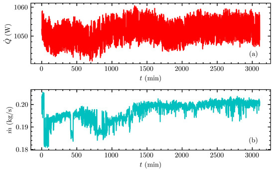
Figure 5.
Beier et al. [37] experiment: (a) ground load and (b) mass flow rate.
Figure 6 shows the inlet and outlet fluid temperatures and the average borehole wall temperatures calculated with the proposed method, (a) the sandbox test and (b) the FEA model, showing good agreement. Both the proposed method and the FEA model were shown to accurately predict temperatures when compared to the experimental results.
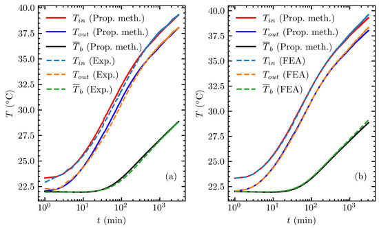
Figure 6.
Comparison of the proposed model with (a) the experimental data of Beier et al. [37] and (b) the FEA model.
The comparison between the proposed model and the experimental data is shown in Figure 6a, resulting in RMSEs for inlet and outlet fluid temperatures and for the average borehole temperature equal to , and C, respectively. The maximum absolute errors for inlet and outlet fluid temperatures occurred at the 76th minute of the simulation and were C and C, respectively. In contrast, the maximum absolute error for the average borehole wall temperature occurred at the 196th minute and was equal to C. The fact that the errors did not occur at the same time for inlet and outlet fluid temperatures and the borehole wall is explained by the fact that the heat transfer process inside the borehole reached a quasi-steady state (or constant heat flux) at a time in the order of . Figure 6b shows the comparison between the FEA model and the proposed method computing inlet and outlet fluid temperature and average borehole wall temperature, similar to what was shown for comparison with the experimental data. For this case, the RMSEs for the inlet and outlet fluid temperatures and average borehole wall temperature were equal to , and C, respectively. The maximum absolute errors for each temperature, , and , occurred at the end of the simulations with values equal to , and C.
Figure 7 shows a comparison of the fluid temperature profiles along the pipes between the proposed model and the FEA model at four different times, corresponding to 1, 10, 100 and 1000 min. Arrows indicate fluid flow direction. For the inlet pipe, the maximum absolute errors for 1, 10, 100 and 1000 min were equal to 0.003, 0.047, 0.013 and 0.125 C. Similarly, for the outlet pipe, the maximum absolute errors were equal to 0.002, 0.048, 0.013 and 0.125 C, corresponding to 1, 10, 100 and 1000 min of the simulation. The maximum absolute errors for inlet and outlet pipes were expected to be approximately equal, since the energy balance is preserved by the ground load in the discretization of the advection equation.
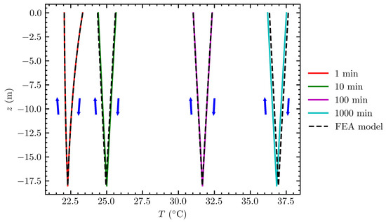
Figure 7.
Fluid temperature profiles along pipes at 4 different times.
The calculation time for Beier’s experiment by means of the proposed method was equal to s, including s for the initialization and s for the solution of the system of equations and coefficient updating scheme.
3.2. Multi-Annual Simulation of a Geothermal Field
Two simulations were used to evaluate the accuracy of the proposed method for long-term and short-term temperature predictions. A first multi-annual simulation was performed for a period of 10 years using a h time step to evaluate the long-term accuracy of the method, followed by a period of 7 days using a time step of 1 min to evaluate the short-term accuracy of the method. The borefield was comprised of 24 boreholes in a rectangular configuration. Every GHE received the same inlet temperature and the same mass flow rate. The parameters used in the simulation are shown in Table 2.

Table 2.
Borefield parameters.
The borefield was divided into equivalent boreholes that shared similar borehole wall temperatures and heat extraction rates using the methodology proposed by Prieto and Cimmino [19]. Figure 8 shows the borefield studied, in this case a rectangular configuration where each consecutive borehole was 6 m equidistant both horizontally and vertically, and the equivalent boreholes were identified. Equivalent boreholes denoted by the numbers I, , each represent 12, 8 and 4 GHEs, respectively. The FEA model was composed of 123,828 6-node prismatic elements with 65,934 nodes in a ground domain, 300 m per side and an axial length equal to 140 m.
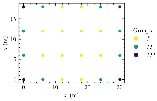
Figure 8.
Equivalent boreholes for a field of 24 GHEs.
3.2.1. Simulation of a 10-Year Period
Figure 9 shows the complete simulation for the first 10 years of heat extraction and heat rejection with the ground (), including inlet and outlet ( and ) temperature and the average borehole wall temperature for each equivalent borehole (, , ) calculated with the proposed method. Figure 9a shows the ground loads ( corresponds to heat extraction with the ground, negative otherwise) for the 10-year period, generated using the synthetic ground load profile of Bernier et al. [42]. The maximum heat extraction and rejection were equal to 93,502 and −76,704 W, respectively. The average net heat transfer for all 10 years was equal to 3761 W, which means an imbalance towards heat extraction. The impact of this imbalance is shown in Figure 9b,c, exhibiting decreasing behavior in both fluid temperatures and borehole wall temperature at the end of the simulation. The maximum and minimum inlet fluid temperatures were and C, respectively, and the maximum and minimum outlet fluid temperatures were and C, respectively. At the end of the simulation, the fluid had a temperature of C for both and , since there was no heat exchange at this time. This represents a difference between the temperature at the beginning of the simulation and the end of the simulation equal to C. For the average borehole wall temperature for each equivalent borehole, the maximum and minimum temperatures in the 10-year period were, respectively, and C for equivalent borehole I; and C for equivalent borehole ; and and C for equivalent borehole . At the end of the simulation, the equivalent boreholes (I, , ) presented average borehole wall temperatures equal to , and C, respectively. Although the variation in the borehole wall temperature between the equivalent boreholes was small, it existed and shows the need to simulate in detail a field composed of several GHEs for larger periods of time. It is also worth mentioning that if the ground loads maintain their imbalance for a longer time, the average borehole wall and fluid temperatures will tend to decrease until they reach steady-state.
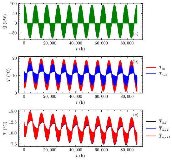
Figure 9.
Multi-annual simulation over 10 years with the proposed method: (a) ground loads, (b) inlet and outlet fluid temperatures and (c) average borehole wall temperature at each equivalent borehole.
Figure 10 compares the inlet and outlet fluid temperatures evaluated with the proposed model and the FEA model. The difference between predicted inlet fluid temperatures is denoted , and the difference between predicted outlet fluid temperatures is denoted . The results corresponding to the time steps of the minimum and maximum differences, and at the end of simulation, are presented in Table 3. Lastly, the RMSEs for the inlet and outlet fluid temperatures were 0.13 and 0.14 C over the 10th simulation year, respectively. Therefore, the inlet and outlet temperatures show good agreement when compared with the FEA model.
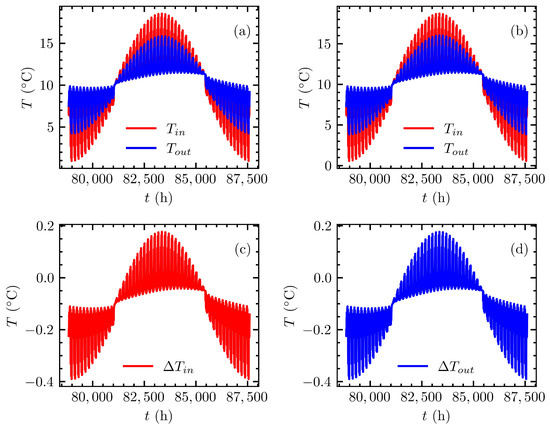
Figure 10.
Comparison of predicted inlet and outlet fluid temperatures during the 10th year: (a) proposed method, (b) FEA model, (c) error of the inlet temperature and (d) error of the outlet temperature.

Table 3.
Errors of fluid temperatures during the 10th year.
The behavior between the soil and the GHE can be studied through the behavior of the borehole wall temperature. For this purpose, according to the groups identified in Figure 8, the average borehole wall temperature for each of the equivalent boreholes was calculated in the FEA model to compare with the proposed methodology. Figure 11 shows the average borehole wall temperature for each of the equivalent boreholes for the proposed method and the FEA model, and the error between each of them for the 10th simulation year. For Figure 11a–c, the average borehole wall temperature for each equivalent borehole was estimated by means of the proposed method; for Figure 11d–f, by the FEA model; and Figure 11g–i shows errors between FEA and the proposed model, for the 10th year. The results corresponding to the time steps of the minimum and maximum differences and at the end of simulation are presented in Table 4. The largest error (in magnitude) was reached when the minimum temperature was reached. The RMSEs between FEA and proposed method were 0.10, 0.09 and 0.10 C, for each equivalent borehole, I, and , respectively. The errors show that the proposed model is able to predict with reasonable accuracy the thermal response between GHE and the soil.
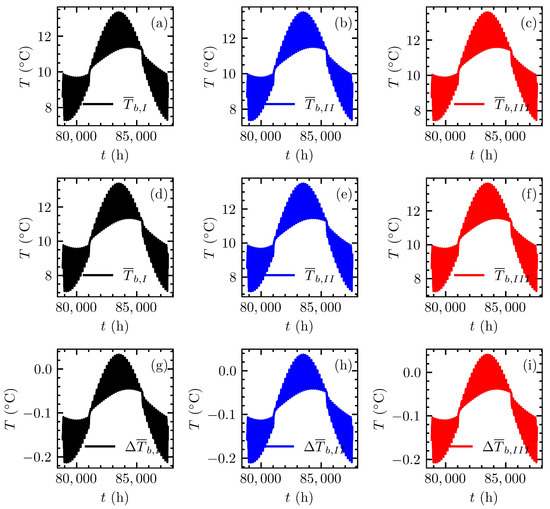
Figure 11.
Comparison of predicted borehole wall temperatures for each equivalent group (I, , ) during the 10th year: (a–c) proposed method, (d–f) FEA model and (g–i) error between models.

Table 4.
Errors on borehole wall temperatures during the 10th year.
The calculation time for this simulation was s: s dedicated to the initialization procedures (i.e., integrals, eigenvalues, coefficients, etc.) and s to the solution of the systems of equations and iterations for the period of 10 years with a time step equal to h.
3.2.2. Short-Term Effects after 10 Years
For the validation of the proposed method with respect to the short-term effects, an additional period of 7 days was simulated following the 10 years of simulation. The time step during this period was set to 1 min. The FEA model was initialized using the final results of the 10-year simulation as initial conditions.
Figure 12 shows the inlet and outlet fluid temperatures and the borehole wall temperatures for each of the equivalent boreholes for the FEA model and the proposed method, and a comparison of the results. Figure 12a,b shows the temperatures obtained using the proposed method, and Figure 12c,d shows the same temperatures obtained with the FEA model. Figure 12e,f shows the differences between the FEA and proposed method. Table 5 presents the inlet and outlet fluid temperatures at the time of the maximum and minimum errors and at the end of the simulation, and the differences between the FEA and the proposed model. The RMSEs between the two models were and C for the inlet and outlet fluid temperatures, respectively. This shows that the proposed method is able to accurately estimate the fluid temperatures when the short-term effects are considered. Table 6 compares the average borehole wall temperatures at each equivalent borehole at the times of the maximum and minimum errors and at the end of the simulation, and the differences between the FEA and the proposed model. The RMSE for each equivalent borehole, I, and , was 0.16, 0.16 and 0.15 C, respectively. As previously noted, these results show good agreement when compared with the FEA model.
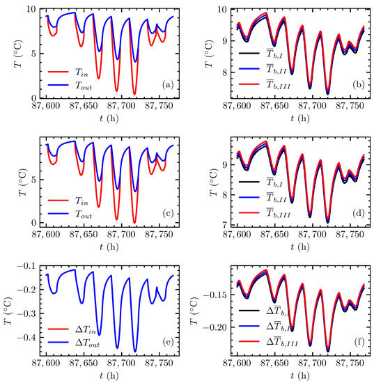
Figure 12.
Comparison of predicted inlet and outlet fluid temperatures and borehole wall temperatures for each equivalent group (I, , ) during the 7-day period: (a,b) proposed method, (c,d) FEA model, (e) errors of the inlet and outlet fluid temperatures, and (f) error of the borehole wall temperatures.

Table 5.
Errors of fluid temperatures during the 7-day period.

Table 6.
Errors of borehole wall temperatures during the 7-day period.
Figure 13 shows the fluid temperature profiles and the borehole wall temperature profiles for each of the equivalent boreholes along their lengths estimated with the proposed method and the FEA for the time step where the largest difference (in magnitude) between the two methods was obtained, which in this case corresponded to 7029 min.
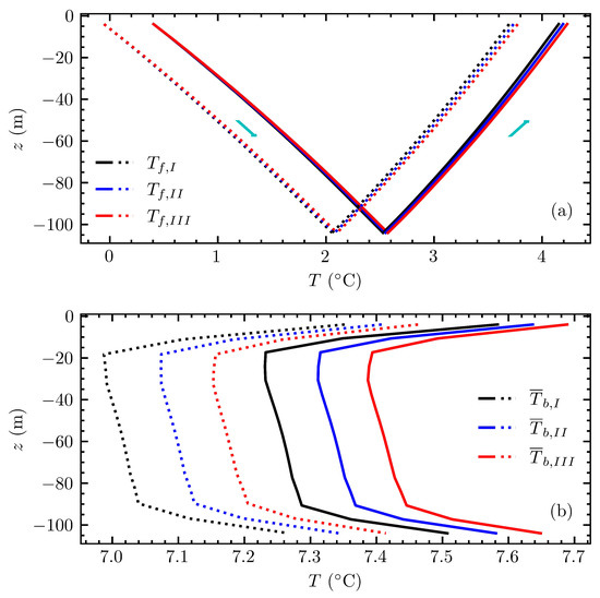
Figure 13.
Fluid and borehole wall temperature profiles for each equivalent borehole at 7029 min: (a) fluid temperature profiles for the FEA (dotted line) and the proposed method (solid line) for each equivalent borehole, and (b) equivalent borehole wall temperature profiles for the FEA method (dotted line) and the proposed method (continuous line).
The arrows indicate the fluid flow direction for each pipe. The inlet temperatures for each equivalent borehole for the FEA and proposed method were equal to −0.05 and 0.4 C, respectively. This amounts to the error previously computed as −0.46 C between FEA and the proposed method. The outlet temperatures for the proposed method were equal to 4.15 C for I, 4.19 C for and 4.23 C for . On the other hand, for the FEA the temperatures were equal to 3.69 C for I, 3.73 C for and 3.76 C for .
Figure 13b shows the equivalent borehole wall temperature profiles along the lengths of the GHEs for the FEA and proposed model. According to results in Table 6, the difference between FEA and proposed method for each equivalent borehole was preserved, and were similar to the differences in the average temperature, being , and C boreholes I, and , respectively. A small difference was observed at all equivalent boreholes, top and bottom, equal to −0.22 C on both parts.
4. Conclusions
This paper presented a novel approach to the study of heat transfer in a field of thermally interacting GHEs where the heat capacity effects of the fluid, grout and soil are included. In the proposed method, the heat transfer inside the GHE is studied by the transient multipole expansion and coupled with the outside of the GHE by penalizing the interior solution with the equivalent borehole method to include the interactions between the GHEs. The advection inside the pipes is modeled by the energy balance along the pipes and discretized using a finite difference scheme. The method drastically reduces the dimensions of the system of equations due to the use of the equivalent borehole method to limit the number of modeled boreholes.
The main contributions of this paper are listed below:
- The method is able to be used in efficient short-term simulations by extending the transient multipole expansion [36] with an efficient coefficient updating scheme to compute fluid and GHE temperatures.
- It is no longer necessary to separate the solutions for short- and long-term effects as done by some researchers [8,24,28], since the heat extraction rates are calculated by the extension of the transient multipole expansion; therefore, the transition between time scales is done naturally by the approaching exact solution. Additionally, no condition is assumed at the borehole wall.
- Calculation times show that it is possible to perform computationally efficient simulations, even when both short- to long-term effects are included. The majority of this calculation time is due to the initialization (210 s on every simulation). The initialization time for the multipole method is independent of the time step and the number of boreholes. The initialization time for the equivalent borehole method is only weakly dependent on the number of boreholes and the number of time steps. The simulations for Beier’s experiment, the 10-year borefield simulation and the 7-day borefield simulation were done in 4 s, 100 s and 16 s, respectively.
The method was first validated against experimental data provided by Beier et al. [37] for a single GHE and against an FEA simulation of the same experiment. The maximum errors for the inlet fluid temperature, outlet fluid temperature and average borehole wall temperature were 0.556, 0.519 and 0.253 C, respectively, when compared to the experimental data; and 0.317, 0.317 and 0.270 C, respectively, when compared to the FEA method. The validation showed that the proposed model compares well with the FEA method, and that both methods compare favorably with the experiment. Differences between the proposed method and the FEA method were expected, since the two methods use different models for the interiors of the GHEs. A 10-year simulation of a field of 24 GHEs was then presented to evaluate the long-term accuracy of the proposed method when compared to the FEA method. A 10 year period was simulated with a h time step, followed by a 7-day period with a time step of 1 min to evaluate the short-term accuracy of the proposed method in the context of long-term simulations. For the 10-year period, the last year presented maximum and minimum differences with the FEA method of 0.18 and −0.39C, respectively, for both the inlet and outlet fluid temperatures. For the 7-day period, the maximum and minimum differences with the FEA method were −0.24 and −0.46 C, respectively, for both the inlet and outlet fluid temperatures.
The method is not restricted to applications where the GHEs are connected in parallel, but could also be extended to consider series connections between the boreholes by modifying the model in Section 2.3. The method could also be extended to include stratified solutions for anisotropic soils, adapting, for example, the solution by Abdelaziz et al. [43]. Additionally, by specific modifications of the FLS solution, the method could include effects such as groundwater flow by making use of proposed solutions such as the moving infinite line source (MILS) by Diao et al. [44], the moving finite line source (MFLS) by Molina-Giraldo et al. [45] or the stratified MFLS by Luo et al. [46]. This will, however, require future work to adapt the equivalent borehole method to consider groundwater flow during the clustering process.
Author Contributions
Conceptualization, C.P. and M.C.; methodology, C.P. and M.C.; software, C.P. and M.C.; validation, C.P.; formal analysis, C.P.; investigation, C.P.; resources, M.C.; data curation, C.P.; writing—original draft preparation, C.P.; writing—review and editing, C.P. and M.C.; visualization, C.P.; supervision, M.C.; project administration, M.C.; funding acquisition, M.C. All authors have read and agreed to the published version of the manuscript.
Funding
This study is funded by the Natural Sciences and Engineering Research Council of Canada (NSERC) (grant number: RGPIN-2018-04471).
Institutional Review Board Statement
Not applicable.
Informed Consent Statement
Not applicable.
Data Availability Statement
Not applicable.
Conflicts of Interest
The authors declare no conflict of interest.
Appendix A. Load Aggregation
The temporal superposition process described in Equation (22), repeated here, is instead solved using a load aggregation algorithm:
The load aggregation algorithm presented by Javed and Claesson [47] is used. The load history is discretized in time using geometrically expanding cells:
where is the width of the first aggregation cell (equal to the simulation time step), is the number of cells per aggregation level, and is the floor operator. Cells are generated until last value is larger than the maximum simulation time.
Each aggregated load contributes to the average borehole wall temperature for each segment as follows:
where are the aggregated loads in each cell p at a time .
For , aggregated loads at a time are calculated according to the aggregated loads on the previous time step :
The first aggregated load () has its value equal to the average load since the last time step. Here, loads are constant during a time step:
Appendix B. Additional Expressions for the Transient Multipole Method
In addition to the expressions presented in Prieto and Cimmino [36], the proposed method requires the evaluation of the average temperatures at the pipe walls () and the average temperature at the borehole wall (), along with their derivatives (e.g., ). Their evaluation necessitates expressions for averages and derivatives of the eigenfunctions () for the homogeneous problem, and the average temperatures () and derivatives for the steady-state non-homogeneous problem.
For the homogeneous problem, the average and derivatives of the eigenfunction at the pipe boundary () are given by:
where
At the borehole wall boundary ():
For the steady-state non-homogeneous problem, the average and derivatives of the multipole expansion at the pipe boundary () are given by:
where
At the borehole wall boundary ():
References
- Lund, J.; Boyd, T. Direct utilization of geothermal energy 2015 worldwide review. Geothermics 2016, 60, 66–93. [Google Scholar] [CrossRef]
- Self, S.; Reddy, B.; Rosen, M. Geothermal heat pump systems: Status review and comparison with other heating options. Appl. Energy 2013, 101, 341–348. [Google Scholar] [CrossRef]
- Bernier, M.; Shirazi, A. Thermal capacity effects in borehole ground heat exchangers. Energy Build. 2013, 67, 352–364. [Google Scholar]
- Ahmadfard, M.; Bernier, M. Modifications to ASHRAE’s Sizing Method for Vertical Ground Heat Exchangers. Sci. Technol. Built Environ. 2018, 24, 803–817. [Google Scholar] [CrossRef]
- Ingersoll, L.; Zobel, O.; Ingersoll, A. Heat Conduction with Engineering and Geological Applications; McGraw-Hill: New York, NY, USA, 1948. [Google Scholar]
- Carslaw, H.; Jaeger, J. Conduction of Heat in Solids; Oxford University Press: Oxford, UK, 1959. [Google Scholar]
- Eskilson, P. Thermal Analysis of Heat Extraction Boreholes. Ph.D. Thesis, University of Lund, Lund, Sweden, 1987. [Google Scholar]
- Claesson, J.; Javed, S. An Analytical Method to Calculate Borehole Fluid Temperatures for Time-scales from Minutes to Decades. ASHRAE Trans. 2011, 117, 279–288. [Google Scholar]
- Lamarche, L.; Beauchamp, B. A new contribution to the finite line-source model for geothermal boreholes. Energy Build. 2007, 39, 188–198. [Google Scholar] [CrossRef]
- Zeng, H.; Diao, N.; Fang, Z. A finite line-source model for boreholes in geothermal heat exchangers. Heat Transf.—Asian Res. 2002, 31, 558–567. [Google Scholar] [CrossRef]
- Cimmino, M.; Bernier, M.; Adams, F. A contribution towards the determination of g-functions using the finite line source. Appl. Therm. Eng. 2013, 51, 401–412. [Google Scholar] [CrossRef]
- Cimmino, M.; Bernier, M. A semi-analytical method to generate g-functions for geothermal borefields. Int. J. Heat Mass Transf. 2014, 70, 641–650. [Google Scholar] [CrossRef]
- Cimmino, M. The effects of borehole thermal resistances and fluid flow rate on the g-functions of geothermal bore fields. Int. J. Heat Mass Transf. 2015, 91, 1119–1127. [Google Scholar] [CrossRef]
- Cimmino, M. Fluid and borehole wall temperature profiles in vertical geothermal boreholes with multiple U-tubes. Renew. Energy 2016, 96, 137–147. [Google Scholar] [CrossRef]
- Cimmino, M. Semi-Analytical Method for g-Function Calculation of Bore Fields with Series- and Parallel-Connected Boreholes. Sci. Technol. Built Environ. 2019, 25, 1007–1022. [Google Scholar] [CrossRef]
- Cimmino, M. A finite line source simulation model for geothermal systems with series- and parallel-connected boreholes and independent fluid loops. J. Build Perform. Simul. 2018, 11, 414–432. [Google Scholar] [CrossRef]
- Lamarche, L. Mixed Arrangement of Multiple Input-Output Borehole Systems. Appl. Therm. Eng. 2017, 124, 466–476. [Google Scholar] [CrossRef]
- Lazzarotto, A. A Network-Based Methodology for the Simulation of Borehole Heat Storage Systems. Renew. Energy 2014, 62, 265–275. [Google Scholar] [CrossRef]
- Prieto, C.; Cimmino, M. Thermal interactions in large irregular fields of geothermal boreholes: The method of equivalent boreholes. J. Build. Perform. Simul. 2021, 14, 446–460. [Google Scholar] [CrossRef]
- Yavuzturk, C.; Spitler, J. A short time step response factor model for vertical ground loop heat exchangers. ASHRAE Trans. 1999, 105, 475–485. [Google Scholar]
- Xu, X.; Spliter, J. Modeling of vertical ground loop heat exchangers with variable convective resistance and thermal mass of the fluid. In Proceedings of the Ecostock America, Pomona, NJ, USA, 31 May–2 June 2006. [Google Scholar]
- Brussieux, Y.; Bernier, M. Universal short-time g*-functions: Generation and application. Sci. Technol. Built Environ. 2019, 25, 993–1006. [Google Scholar] [CrossRef]
- Javed, S.; Claesson, J. New analytical and numerical solutions for the short-term analysis of vertical ground heat exchangers. ASHRAE Trans. 2011, 117, 3–12. [Google Scholar]
- Li, M.; Li, P.; Chan, V.; Lai, A. Full-scale temperature response function (G-function) for heat transfer by borehole ground heat exchangers (GHEs) from sub-hour to decades. Appl. Energy 2014, 136, 197–205. [Google Scholar] [CrossRef]
- Li, M.; Lai, A. Analytical model for short-time responses of ground heat exchangers with U-shaped tubes: Model development and validation. Appl. Energy 2013, 104, 510–516. [Google Scholar] [CrossRef]
- Monzó, P.; Puttige, A.; Acuña, J.; Mogensen, P.; Cazorla, A.; Rodriguez, J.; Montagud, C.; Cerdeira, F. Numerical modeling of ground thermal response with borehole heat exchangers connected in parallel. Energy Build. 2018, 172, 371–384. [Google Scholar] [CrossRef] [Green Version]
- Pasquier, P.; Marcotte, D. Joint use of quasi-3D response model and spectral method to simulate borehole heat exchanger. Renew. Energy 2014, 51, 281–299. [Google Scholar] [CrossRef]
- Laferrière, A.; Cimmino, M.; Picard, D.; Helsen, L. Development and validation of a full-time-scale semi-analytical model for the short- and long-term simulation of vertical geothermal bore fields. Geothermics 2020, 86, 101788. [Google Scholar] [CrossRef]
- Bauer, D.; Heidemann, W.; Diersch, H.-J.G. Transient 3D analysis of borehole heat exchanger modeling. Geothermics 2011, 40, 250–260. [Google Scholar] [CrossRef]
- Alaie, O.; Maddahian, R.; Heidarinejad, G. Investigation of thermal interaction between shallow boreholes in a GSHE using the FLS-STRCM model. Renew. Energy 2021, 175, 1137–1150. [Google Scholar] [CrossRef]
- Minaei, A.; Maerefat, M. Thermal resistance capacity model for short-term borehole heat exchanger simulation with non-stiff ordinary differential equations. Geothermic 2017, 70, 260–270. [Google Scholar] [CrossRef]
- Al-Khoury, R.; Bonnier, P.G. Efficient finite element formulation for geothermal heating systems. Part II: Transient. Int. J. Num. Meth. Eng. 2006, 67, 725–745. [Google Scholar] [CrossRef]
- Diersch, H.-J.G.; Bauer, D.; Heidemann, W.; Rühaak, W.; Schätzl, P. Finite element modeling of borehole heat exchanger systems: Part 1. Fundamentals. Comp. Geosci. 2011, 37, 1122–1135. [Google Scholar]
- Diersch, H.-J.G.; Bauer, D.; Heidemann, W.; Rühaak, W.; Schätzl, P. Finite element modeling of borehole heat exchanger systems: Part 2. Numerical simulation. Comp. Geosci. 2011, 37, 1136–1147. [Google Scholar] [CrossRef]
- Rivero, J.M.; Hermanns, M. Enhanced multipole method for the transient thermal response of slender geothermal boreholes. Int. J. Therm. Sci. 2021, 164, 106531. [Google Scholar] [CrossRef]
- Prieto, C.; Cimmino, M. Transient multipole expansion for heat transfer in ground heat exchangers. Sci. Technol. Built Environ. 2021, 27, 253–270. [Google Scholar] [CrossRef]
- Beier, R.; Smith, M.; Spitler, J. Reference data sets for vertical borehole ground heat exchanger models and thermal response test analysis. Geothermics 2001, 40, 79–85. [Google Scholar] [CrossRef]
- Cimmino, M. pygfunction: An open-source toolbox for the evaluation of thermal response factors for geothermal borehole fields. In Proceedings of the eSim, Montreal, QC, Canada, 9–10 May 2018; pp. 492–501. [Google Scholar]
- Bauer, D.; Heidemann, W.; Müller-Steinhagen, H.; Diersch, H.-J.G. Thermal resistance and capacity models for borehole heat exchangers. Int. J. Energy Res. 2011, 35, 312–320. [Google Scholar] [CrossRef]
- DHI-WASY. FEFLOW Finite Element Subsurface Flow and Transport Simulation System—White Papers; DHI-WASY: Berlin, Germany, 2010; Volume 5. [Google Scholar]
- Eskilson, P.; Claesson, J. Simulation model for thermally interacting heat extraction boreholes. Num. Heat Transf. 1988, 13, 149–165. [Google Scholar]
- Bernier, M.; Pinel, P.; Labib, R.; Paillot, R. A Multiple Load Aggregation Algorithm for Annual Hourly Simulations of GCHP Systems. HVAC R Res. 2004, 10, 471–487. [Google Scholar] [CrossRef]
- Abdelaziz, S.; Ozudogru, T.; Olgun, C.; Martin, J. Multilayer Finite Line Source Model for Vertical Heat Exchangers. Geothermics 2014, 51, 406–416. [Google Scholar] [CrossRef]
- Diao, N.; Li, Q.; Fang, Z. Heat transfer in ground heat exchangers with groundwater advection. Int. J. Therm. Sci. 2004, 43, 1203–1211. [Google Scholar] [CrossRef]
- Molina-Giraldo, N.; Blum, P.; Zhu, K.; Bayer, P.; Fang, Z. A moving finite line source model to simulate borehole heat exchangers with groundwater advection. Int. J. Therm. Sci. 2011, 50, 2506–2513. [Google Scholar] [CrossRef]
- Luo, Y.; Cheng, N.; Xu, G. Analytical modeling and thermal analysis of deep coaxial borehole heat exchanger with stratified-seepage-segmented finite line source method (S3-FLS). Energy Build. 2022, 257, 111795. [Google Scholar] [CrossRef]
- Javed, S.; Claesson, J. A load aggregation method to calculate extraction temperaturesof borehole heat exchangers. ASHRAE Trans. 2012, 118, 530–539. [Google Scholar]
Publisher’s Note: MDPI stays neutral with regard to jurisdictional claims in published maps and institutional affiliations. |
© 2022 by the authors. Licensee MDPI, Basel, Switzerland. This article is an open access article distributed under the terms and conditions of the Creative Commons Attribution (CC BY) license (https://creativecommons.org/licenses/by/4.0/).