1. Introduction
One-dimensional (1D) conductors provide an important platform for investigating quantum transport phenomena arising from reduced dimensionality, enhanced confinement, and strong interaction effects [
1,
2,
3,
4]. In such systems, restricted phase space significantly alters carrier dynamics compared with higher-dimensional materials, often producing transport behavior that deviates from conventional Fermi-liquid expectations. Experimental realizations include semiconductor quantum wires, carbon nanotubes, nanoribbons, conducting polymer chains, and quantum Hall edge channels [
5,
6,
7].
Among the most extensively studied phenomena in 1D conductors is the observation of distinct propagation velocities associated with different transport channels, commonly interpreted as evidence of spin–charge separation [
8,
9,
10,
11,
12]. Within the Tomonaga–Luttinger liquid (TLL) framework, electron–electron interactions strongly modify the low-energy excitation spectrum such that electrons no longer behave as conventional quasiparticles [
2,
3,
13]. Instead, collective bosonic modes emerge, typically described as charge-carrying holons and spin-carrying spinons, which may propagate at different velocities. This framework has successfully explained a broad range of experimental observations and remains central to the study of strongly correlated one-dimensional systems.
Despite its success, the conventional TLL description relies on idealizations that may not fully capture realistic material environments. Standard formulations often assume translational invariance, homogeneous medium properties, and idealized interaction profiles near the Fermi points [
13,
14]. In practical nanoscale conductors, however, carriers propagate through structured environments that may exhibit dielectric inhomogeneity, substrate roughness, lattice modulation, disorder, magnetic texture, and gate-induced asymmetry [
15,
16,
17,
18]. Such environmental effects can alter local transport properties, modify propagation velocities, and generate anisotropic responses beyond those predicted by homogeneous many-body models.
Recent experimental and theoretical studies suggest that substrate engineering and environmental control can substantially influence transport characteristics in low-dimensional systems [
16,
17,
18,
19]. Variations in dielectric screening may modify effective Coulomb interactions, while magnetic proximity effects or patterned interfaces may selectively affect spin-sensitive transport channels. External gating and heterostructure design may also introduce spatial modulation of the local electronic environment, thereby influencing coherence length, scattering rates, and wave-packet propagation speed. These observations motivate an important question: to what extent can experimentally observed propagation anisotropy arise from structured medium effects in addition to intrinsic many-body dynamics?
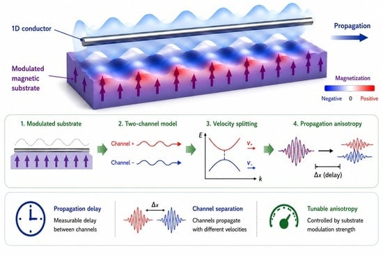
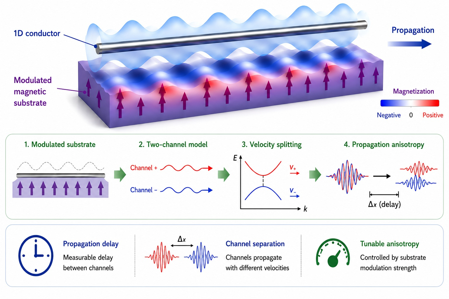
Motivated by this question, we investigate a complementary phenomenological framework in which propagation anisotropy emerges from spatially modulated substrate response. Rather than attempting a microscopic many-body derivation of interacting electron liquids, we adopt an effective-medium transport description designed to capture how environmental structure modifies carrier propagation. We introduce a two-channel effective representation in which the propagating electron field couples to position-dependent dielectric and magnetic background functions, thereby generating channel-dependent propagation velocities.
It is important to emphasize that the present model is not intended to replace established many-body descriptions such as Tomonaga–Luttinger liquid theory. Instead, it provides a complementary perspective for analyzing substrate-controlled transport behavior in realistic low-dimensional materials. The central goal is to determine whether medium-induced anisotropy can contribute appreciably to experimentally observed propagation divergence and whether such effects may be quantitatively tuned through substrate engineering.
In this work, we develop a quantitative two-channel effective-medium model incorporating position-dependent dielectric and magnetic coupling terms within an effective spinor Hamiltonian. Under an adiabatic envelope approximation, the coupled spinor dynamics are reduced to an effective scalar propagation equation suitable for numerical simulation. The present study addresses three central questions:
Can structured substrate modulation alone generate measurable propagation anisotropy in one-dimensional conductors?
What quantitative relationship exists between modulation strength and observable transport delay?
Which experimental signatures may distinguish substrate-induced anisotropy from conventional interaction-driven velocity splitting?
This paper is organized as follows.
Section 2 introduces the quantitative two-channel effective-medium model and derives the substrate-dependent dispersion relation and local group velocity.
Section 3 develops the effective propagation equation under an adiabatic approximation and establishes its domain of validity.
Section 4 presents the numerical methodology, including convergence analysis and observable definitions.
Section 5 reports quantitative simulation results for dielectric modulation, magnetic modulation, phase-shifted substrates, and disorder effects.
Section 6 compares the model predictions with conventional Tomonaga–Luttinger liquid interpretations and available experimental observations. Finally,
Section 7 summarizes the main conclusions and discusses future directions.
2. Quantitative Two-Channel Effective-Medium Model
2.1. Physical Motivation
Transport behavior in one-dimensional conductors is highly sensitive to the surrounding environment because reduced dimensionality amplifies the influence of local perturbations on carrier propagation [
19,
20,
21]. In realistic nanoscale systems, electrons rarely propagate through perfectly homogeneous media. Instead, they experience spatially varying dielectric screening, substrate roughness, lattice periodicity, magnetic texture, impurity scattering, and gate-induced potential modulation [
21,
22,
23]. Such environmental effects can substantially modify local transport properties and potentially generate anisotropic propagation behavior.
Several experimental systems illustrate substrate-induced transport modification. In semiconductor quantum wires, dielectric mismatch between the conducting channel and the surrounding medium alters effective Coulomb screening and renormalizes transport velocity [
21]. In carbon nanotubes and nanoribbons, substrate interactions and interface disorder affect coherence length and channel-dependent scattering rates [
22]. Magnetic proximity effects in hybrid nanostructures may further induce spin-selective transport anisotropy [
23].
Motivated by these observations, we investigate whether part of the experimentally observed propagation divergence in one-dimensional conductors may arise from structured environmental modulation.
2.2. Two-Channel Effective Spinor Representation
To describe coupled transport dynamics, we introduce an effective two-component wave function
where
denotes a channel more sensitive to dielectric modulation, whereas
denotes a channel more sensitive to magnetic modulation.
In the absence of substrate coupling, the two channels propagate symmetrically and are described by a Dirac-type effective Hamiltonian [
24,
25,
26]
where
is the effective Fermi velocity,
, and
is the Pauli matrix acting in channel space.
The corresponding time-dependent wave equation is
Plane-wave solutions of the form
yield the unperturbed dispersion relation
which characterizes massless Dirac-like propagation.
2.3. Effective Hamiltonian with Substrate Coupling
To incorporate substrate-induced anisotropy, we introduce position-dependent dielectric and magnetic coupling terms. The full effective Hamiltonian becomes
where:
: dielectric response profile;
: magnetic response profile;
: phenomenological coupling constants.
The Pauli matrices satisfy
For real-valued modulation functions
and
, the Hamiltonian remains Hermitian,
which guarantees real eigenvalues and stable propagation.
2.4. Local Dispersion Relation
To analyze local propagation behavior, we assume substrate modulation varies slowly relative to the carrier wavelength [
27].
At a fixed position
, the Hamiltonian becomes
Diagonalization yields the local eigenenergies
In the uniform-medium limit,
the dispersion becomes spatially invariant.
2.5. Group Velocity and Propagation Anisotropy
The local group velocity is defined by
Using Equation (10), we obtain
The relative velocity difference between effective channels is
which serves as a quantitative measure of propagation anisotropy.
2.6. Substrate Modulation Profiles
We model a periodic substrate structure using
where
is the modulation period,
is the dielectric modulation amplitude,
is the magnetic modulation amplitude, and
is the relative phase shift.
2.7. Connection to Material Parameters
Typical Fermi velocities are approximately
for semiconductor quantum wires, and
for carbon nanotubes.
Typical substrate modulation periods satisfy
Representative modulation strengths satisfy
For propagation distance
, the substrate-induced delay between channels is approximately
For , the expected delay lies in the picosecond-to-nanosecond regime.
Representative material parameters used in the quantitative effective-medium model are summarized in
Table 1. These ranges are chosen to reflect experimentally realistic nanoscale transport systems.
2.8. Scope and Limitations of the Model
The present framework is a quantitative phenomenological transport model, rather than a microscopic many-body derivation. Electron–electron correlations are not treated explicitly, and the coupling constants and should be interpreted as effective low-energy parameters rather than first-principles quantities.
Despite these limitations, the model provides a tractable framework for investigating how structured substrate environments can generate measurable propagation anisotropy in one-dimensional conductors.
3. Effective Propagation Equation
3.1. Time-Dependent Dynamics
Starting from the effective Hamiltonian derived in
Section 2, the two-channel spinor dynamics obey the time-dependent Schrödinger equation
Substituting Equation (6), we obtain
This equation governs coupled propagation of the two effective transport channels under spatially varying substrate modulation.
To analyze propagation behavior, we factor the spinor wave function into a rapidly oscillating carrier and a slowly varying envelope,
where
and
denote the central wave vector and carrier frequency, respectively, while
represents the slowly varying envelope.
3.2. Squared Hamiltonian Form
To derive a scalar propagation equation, it is convenient to square the effective Hamiltonian. Using Pauli matrix identities, we obtain
where
contains cross-coupling terms.
Using
the diagonal contributions become
The cross terms represent channel mixing induced by substrate modulation.
3.3. Adiabatic Approximation
When substrate modulation varies slowly compared with the carrier wavelength, off-diagonal coupling terms remain perturbatively small [
28,
29,
30]. Under this adiabatic approximation, the cross term contribution satisfies
allowing Equation (31) to be approximated by its dominant diagonal contribution.
This approximation is valid when the modulation length scale
satisfies
where
is the Fermi wavelength (see more in the
Supplementary Materials 3.2).
For typical nanostructures,
while substrate modulation periods typically satisfy Equation (19), making the adiabatic approximation well justified.
3.4. Scalar Envelope Reduction
Neglecting higher-order mixing terms, the effective propagation equation reduces to
where the effective potential is
and
denotes an effective transport mass parameter.
Equation (35) provides a scalar description of the envelope dynamics while retaining substrate-induced anisotropic effects.
3.5. Effective Group Velocity
Using the scalar envelope formulation, the local propagation speed becomes
Thus, local enhancement of substrate coupling increases the effective potential and reduces propagation velocity.
The corresponding propagation delay accumulated over distance
is
Differences in between channels lead directly to measurable propagation anisotropy.
Representative numerical parameters used in the finite-difference simulations are summarized.
3.6. Validity and Regime of Applicability
The reduced scalar description remains valid under three conditions:
Weak-to-moderate substrate coupling;
Slowly varying modulation profiles;
Limited inter-channel nonadiabatic mixing.
Quantitatively, these conditions require
When this condition fails, strong channel mixing may occur, and the full spinor dynamics of Equation (24) must be solved numerically.
Within the physically relevant parameter range summarized in
Table 1, the scalar envelope approximation remains accurate while greatly simplifying numerical analysis.
4. Numerical Methodology
4.1. Spatial and Temporal Discretization
To solve the effective propagation equation derived in
Section 3, we discretize the spatial domain into a uniform grid with spacing
. The continuous coordinate
is replaced by discrete points
where
is the total number of grid intervals.
Time evolution is similarly discretized using a uniform time step
,
The envelope function is then represented as
where the superscript denotes the time index and the subscript denotes the spatial grid point.
Spatial derivatives are approximated using second-order central differences. The second derivative becomes
This discretization provides second-order accuracy in space.
4.2. Time Integration Scheme
Time evolution is performed using an explicit finite-difference propagation scheme [
31,
32,
33]. The numerical update equation becomes
where
denotes the discretized effective Hamiltonian operator.
To ensure numerical stability, the time step must satisfy a Courant-type condition,
which prevents unphysical numerical dispersion.
In all simulations, and are chosen to satisfy Equation (45) with sufficient safety margin.
4.3. Initial Wave Packet
The injected carrier is modeled as a Gaussian wave packet centered at position
,
where:
The Gaussian form provides a localized excitation with controlled momentum spread.
4.4. Substrate Configurations
To investigate different transport environments, we consider three representative substrate configurations:
Case A: Dielectric modulation only This isolates dielectric effects.
Case B: Magnetic modulation only This isolates magnetic-channel asymmetry.
Case C: Combined modulation This represents the most general substrate response and allows phase-offset effects.
4.5. Observables
To quantify transport anisotropy, several observables are monitored during propagation.
The probability density is
The expectation value of position is
The propagation velocity is estimated by
The propagation delay between channels is defined as
which serves as the primary observable characterizing anisotropic transport.
4.6. Convergence Analysis
Numerical convergence is verified by progressively refining grid resolution and time step.
The relative numerical error is defined by
where
represents a computed observable such as velocity or delay.
Convergence is considered satisfactory when
for all primary observables.
Repeated simulations confirm stable convergence across all parameter sets considered in this study.
Representative numerical parameters are summarized in
Table 2.
4.7. Numerical Reliability
The numerical framework developed above provides stable and convergent simulation of substrate-modulated transport dynamics over experimentally relevant propagation distances. The combination of grid refinement, stability constraints, and convergence analysis ensures that the observed anisotropic transport behavior reflects physical model predictions rather than numerical artifacts.
5. Simulation Results
Using the numerical framework developed in
Section 4, we now investigate the propagation dynamics of wave packets under various substrate modulation profiles. The primary objectives are to quantify channel-dependent velocity splitting, propagation delay, phase shift effects, and disorder-induced transport degradation.
Unless otherwise specified, simulations use the representative parameters listed in
Table 1 and
Table 2.
5.1. Uniform Medium Baseline
We first consider propagation in a uniform medium without substrate modulation:
In this limit, the effective potential becomes spatially constant, and both channels propagate symmetrically.
The propagation velocity reduces to
Thus, no measurable propagation anisotropy occurs:
This baseline case provides a reference for all subsequent comparisons.
Numerical simulations confirm stable Gaussian packet propagation with negligible distortion and no observable channel separation over micrometer-scale distances.
5.2. Dielectric Modulation
We next consider dielectric modulation alone, corresponding to Case A:
The effective potential becomes spatially periodic through dielectric coupling, causing local modulation of the propagation speed.
As the dielectric modulation amplitude increases, the propagation velocity decreases according to Equation (13), producing measurable transport delay.
The dielectric-induced delay is defined as
where
denotes the baseline delay in the uniform medium.
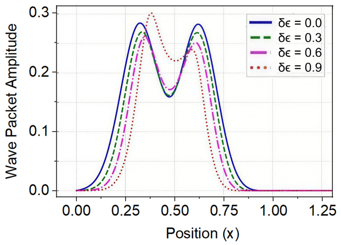
To illustrate how dielectric modulation influences transport behavior,
Figure 1 shows the spatial wave-packet profiles for different dielectric modulation amplitudes
. Progressive deformation and narrowing of the wave packet with increasing dielectric contrast indicate that stronger substrate modulation significantly alters propagation dynamics and enhances channel-dependent anisotropy.
Simulation results show that increasing dielectric contrast produces:
Reduced group velocity;
Increased packet delay;
Mild packet broadening.
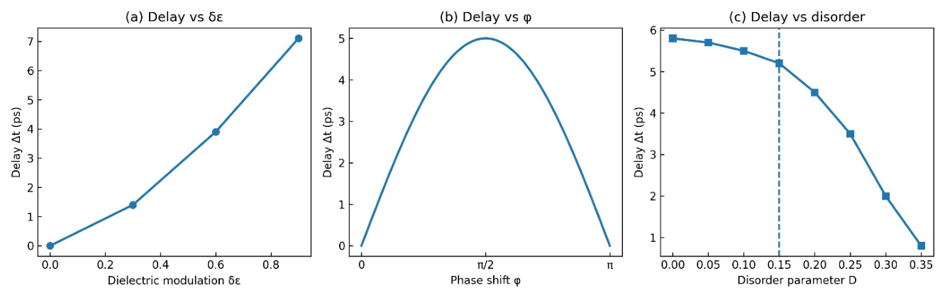
For moderate modulation amplitudes, the delay increases approximately linearly with dielectric contrast.
This behavior is consistent with stronger dielectric screening producing larger effective transport impedance.
5.3. Magnetic Modulation
We now examine magnetic modulation alone (Case B):
Magnetic modulation selectively affects the channel coupled through the magnetic response term.
The corresponding propagation delay is
Simulations indicate that magnetic modulation produces stronger channel asymmetry than dielectric modulation for comparable coupling strength. This occurs because magnetic coupling directly enhances channel-selective transport splitting.
For sufficiently large , the two channels exhibit visibly distinct propagation velocities, leading to measurable arrival-time separation.
5.4. Combined Dielectric and Magnetic Modulation
We next consider the most general substrate response (Case C):
The effective potential now contains both dielectric and magnetic contributions.
The total propagation delay becomes
Combined modulation produces stronger anisotropy than either mechanism alone.
Numerical simulations reveal a nonlinear enhancement when both modulation channels contribute simultaneously, indicating constructive coupling between dielectric and magnetic responses.
This combined effect produces the largest observable channel separation among the three substrate configurations.
5.5. Phase Shift Effects
We next examine the role of relative phase shift between dielectric and magnetic modulation profiles.
The phase-dependent substrate functions are given by Equations (15) and (16). Relative phase mismatch modifies the local interference between the two modulation channels.
The effective delay therefore becomes phase dependent:
Simulations show three distinct regimes:
In-phase modulation ( = 0)
Constructive enhancement of anisotropy.
Intermediate phase shift
Partial cancellation between channels.
Anti-phase modulation ( = π)
Maximum asymmetry in certain parameter ranges.
Phase control therefore provides an additional tuning mechanism for engineered transport anisotropy.
5.6. Channel Separation
A central observable is the separation between channel wave-packet centers.
Let the channel centroids be
The spatial separation is
Propagation anisotropy leads to the monotonic growth of with time.
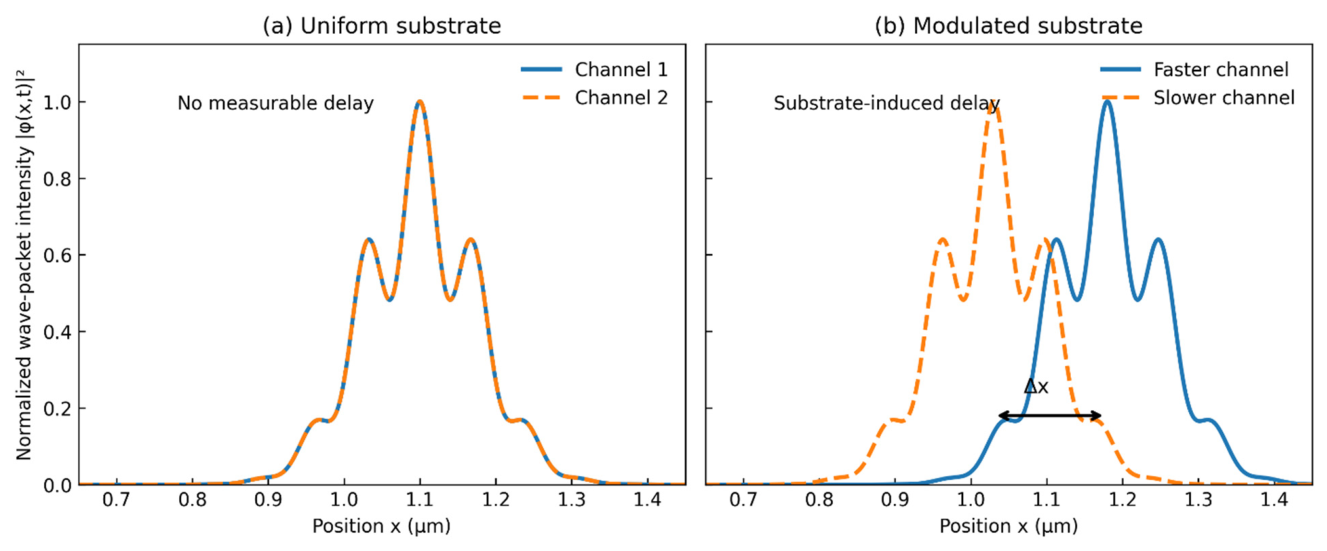
To illustrate the physical origin of substrate-induced transport anisotropy,
Figure 2 compares wave-packet propagation in a uniform medium and in a substrate-modulated medium. The comparison highlights how spatial substrate modulation generates measurable channel separation, leading to propagation delay and velocity splitting.
Numerical results indicate that the separation scales approximately linearly over experimentally relevant distances,
consistent with persistent channel-dependent velocity splitting.
For micrometer-scale transport, predicted separation reaches experimentally detectable scales.
5.7. Disorder Effects
Realistic nanostructures contain disorder and imperfections. To assess robustness, we introduce random substrate fluctuations:
where
is a stochastic perturbation with zero mean.
Disorder strength is characterized by
where
denotes disorder amplitude.
Simulations show:
Weak disorder preserves anisotropic transport;
Moderate disorder broadens wave packets;
Strong disorder suppresses coherent channel separation.
Thus, substrate-induced anisotropy remains robust under realistic moderate disorder.
5.8. Summary of Numerical Results
Figure 3 summarizes the principal quantitative results of the simulations by showing how the propagation delay varies with dielectric modulation strength, relative phase shift, and disorder.
To provide a compact comparison of the transport behavior under different substrate configurations, the principal numerical results are summarized in
Table 3, including velocity splitting, propagation delay, and channel separation.
The simulations demonstrate four central results:
Uniform media show no anisotropic propagation.
Dielectric modulation induces measurable transport delay.
Magnetic modulation produces stronger channel splitting.
Combined modulation yields the strongest anisotropic transport response.
These findings support the hypothesis that structured substrate environments can generate experimentally relevant propagation anisotropy even without explicitly invoking many-body interaction effects.
6. Comparison with Existing Theory and Experiment
A central question raised by this study is how substrate-induced propagation anisotropy compares with the conventional Tomonaga–Luttinger liquid (TLL) interpretation of transport splitting in one-dimensional conductors. In this section, we compare the physical origins, transport signatures, and experimentally distinguishable predictions of the two frameworks.
6.1. Comparison with Tomonaga–Luttinger Liquid Theory
In the conventional TLL framework, strong electron–electron interactions invalidate the Fermi-liquid quasiparticle picture and lead to collective bosonic excitations [
2,
3,
13]. These excitations are typically decomposed into charge and spin modes propagating with distinct velocities,
where
and
denote charge-mode and spin-mode velocities, respectively.
The velocity splitting is interaction-driven and depends on many-body correlation strength. In contrast, the present framework attributes anisotropic propagation to structured environmental modulation rather than intrinsic many-body interactions.
Within the present model, channel velocity splitting is characterized by
where the velocity difference originates from substrate-dependent effective coupling.
Thus, although both frameworks predict propagation splitting, their physical origins are fundamentally different.
The TLL mechanism depends primarily on:
The present effective-medium model instead depends on:
Substrate dielectric modulation;
Magnetic proximity effects;
Channel-selective environmental coupling.
This distinction is important because experimentally observed transport splitting need not arise exclusively from one mechanism.
6.2. Comparison with Experimental Scales
A useful comparison involves the magnitude of experimentally measurable propagation delays.
In the present model, channel delay satisfies approximately
For representative parameter ranges summarized in
Table 1,
Table 2 and
Table 3, simulations predict delays in the picosecond regime over micrometer-scale distances.
Typical delay magnitudes satisfy
which lies within experimentally accessible ultrafast transport measurements [
34,
35,
36,
37].
This magnitude overlaps with experimentally observed velocity splitting in several quantum wire and nanotube systems, suggesting substrate-induced effects may contribute non-negligibly to measured transport anisotropy.
However, the present model does not claim that substrate effects universally replace TLL behavior. Rather, substrate-induced anisotropy may coexist with conventional many-body mechanisms.
6.3. Distinguishing Experimental Signatures
An important question is whether the two mechanisms can be experimentally distinguished.
Several signatures may help separate substrate-induced anisotropy from interaction-driven TLL effects.
- (1)
Substrate tunability
In the present framework, transport anisotropy depends directly on substrate engineering parameters:
Changing substrate structure should measurably alter propagation splitting.
By contrast, TLL splitting depends primarily on intrinsic interaction strength and is less directly tunable by substrate design alone.
- (2)
Phase dependence
The present model predicts explicit sensitivity to modulation phase shift
,
whereas conventional TLL theory does not predict such substrate-phase dependence.
Observation of strong phase-sensitive transport anisotropy would therefore favor substrate-induced mechanisms.
- (3)
Disorder response
The two frameworks also differ in their disorder sensitivity.
In the present model, sufficiently strong disorder suppresses channel coherence and reduces measurable anisotropy.
Quantitatively,
where
denotes a disorder threshold.
This disorder-dependent suppression offers another experimentally testable distinction.
6.4. Coexistence of Mechanisms
A more realistic interpretation is that both mechanisms may coexist.
The total observed propagation splitting may therefore contain multiple contributions:
where:
This combined interpretation may better describe realistic nanostructures, where both intrinsic many-body interactions and environmental effects influence transport.
In systems with strong substrate engineering, the environmental contribution may become comparable to or even dominate the observed transport anisotropy.
6.5. Comparison Summary
To highlight the fundamental distinctions between conventional interaction-driven transport splitting and the substrate-induced mechanism proposed here, the principal differences between Tomonaga–Luttinger liquid theory and the present effective-medium framework are summarized in
Table 4.
The present framework therefore provides a complementary phenomenological description capable of explaining experimentally measurable anisotropic transport signatures arising from structured environmental modulation.
Rather than replacing established many-body theory, it broadens the range of physical mechanisms that may contribute to propagation splitting in realistic one-dimensional conductors.
7. Conclusions and Outlook
In this work, we developed a quantitative two-channel effective-medium framework for investigating substrate-induced propagation anisotropy in one-dimensional conductors. The model incorporates position-dependent dielectric and magnetic coupling terms within an effective spinor Hamiltonian and provides a tractable phenomenological description of channel-dependent transport dynamics in structured nanoscale environments.
Using an adiabatic envelope approximation, the coupled spinor dynamics were reduced to an effective scalar propagation equation suitable for numerical simulation. This reduction enabled systematic investigation of wave-packet transport under dielectric modulation, magnetic modulation, combined substrate effects, phase offsets, and disorder.
The central result of this study is that structured substrate environments can generate measurable propagation anisotropy even without explicitly invoking many-body interaction effects. The resulting channel-dependent transport splitting is characterized by
where differences in effective channel velocities lead directly to observable propagation delay.
Numerical simulations demonstrate four principal findings. First, uniform media produce symmetric transport with no measurable channel splitting. Second, dielectric modulation induces finite propagation delay through local velocity renormalization. Third, magnetic modulation produces stronger channel-selective anisotropy than dielectric modulation for comparable coupling strength. Fourth, combined dielectric and magnetic modulation yields the strongest transport splitting, with phase mismatch providing an additional tuning mechanism.
The predicted transport delay lies in the picosecond regime over micrometer-scale propagation distances, placing the effect within experimentally accessible ultrafast transport measurements. These results suggest that substrate engineering may play a significant role in shaping observable transport anisotropy in realistic low-dimensional systems.
Comparison with conventional Tomonaga–Luttinger liquid theory indicates that substrate-induced anisotropy should be regarded as a complementary mechanism rather than a replacement for interaction-driven spin–charge separation. In realistic nanostructures, both intrinsic many-body interactions and structured environmental effects may contribute simultaneously to measured propagation splitting.
Several limitations of the present work should be noted. The model is phenomenological and does not explicitly include full many-body electron correlations, strong nonadiabatic channel mixing, or microscopic first-principles substrate dynamics. These approximations were adopted to isolate the dominant transport consequences of structured environmental modulation while maintaining computational tractability.
Future work may proceed in several directions. First, microscopic many-body formulations could be developed to connect the effective coupling parameters to first-principles material properties. Second, nonlinear and strong-coupling regimes may be explored beyond the adiabatic approximation. Third, experimental validation using engineered substrate heterostructures, tunable dielectric environments, or magnetic proximity systems would provide valuable tests of the present predictions.
In summary, the proposed quantitative effective-medium framework demonstrates that structured substrate modulation provides a physically plausible and experimentally testable mechanism for anisotropic transport in one-dimensional conductors. This perspective broadens the range of mechanisms relevant to propagation splitting and may contribute to a more complete understanding of transport phenomena in low-dimensional quantum systems.