
Article

Through Analysis of Thin Films Based on Small-Molecule and Polymer NFA Blends for Photovoltaic Conversion: From Neat Materials to Ternary Systems

by
Mohamed el A. Kramdi
1,2,
Aral Karahan
1,
Takeshi Watanabe
3,
Hidehiro Sekimoto
4,
Simon Desbief
1,
Gilles Quéléver
1,
Olivier Margeat
1,
Jörg Ackermann
1,
Carmen M. Ruiz Herrero
2 and
Christine Videlot-Ackermann
1,*
1
Aix-Marseille University, CNRS, CINAM, 13007 Marseille, France
2
IM2NP, Aix-Marseille Université, 13397 Marseille, France
3
Industrial Application Division, Japan Synchrotron Radiation Research Institute (JASRI), Sayo 679-5198, Japan
4
Department of Physical Science and Materials Engineering, Iwate University, Morioka 020-8551, Japan
*
Author to whom correspondence should be addressed.
Physchem 2026, 6(1), 12; https://doi.org/10.3390/physchem6010012
Submission received: 16 November 2025 / Revised: 23 January 2026 / Accepted: 4 February 2026 / Published: 9 February 2026
(This article belongs to the Topic Polymer Physics)

Abstract

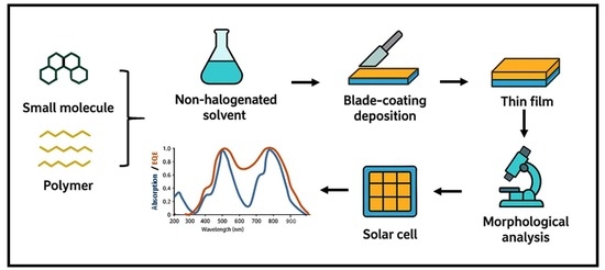
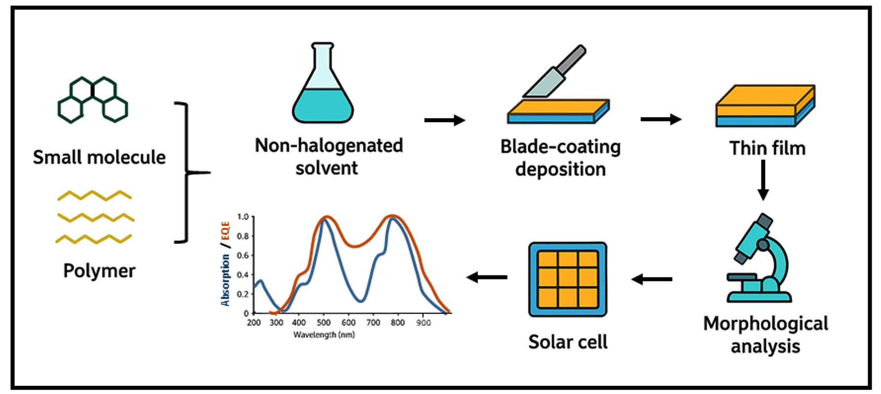
Focusing on PM6 as the electron-donating polymer and the non-fullerene acceptors Y12 and PY-IT, this study investigates their chemical, optical, and morphological properties, as well as their compatibility in bulk heterojunction (BHJ) architectures. All materials were characterized in thin-film form using Fourier transform infrared (FTIR), and Raman spectroscopy. Binary blends of PM6:Y12 and PM6:PY-IT, along with the ternary PM6:PY-IT:Y12 system, were dissolved in o-xylene and processed into active layers by blade coating under ambient conditions. Optical properties were analyzed in solution and in thin films, providing insights into light-absorption efficiency and spectral complementarity. Nanoscale morphology and molecular packing were examined using atomic force microscopy (AFM) and grazing-incidence wide-angle X-ray scattering (GIWAXS), revealing correlations between material organization and device performance. The results highlight the importance of optimizing material selection, ink formulation, and film morphology to maximize charge-generation efficiency. Power-conversion efficiencies (PCEs) of 13.95%, 12.04%, and 12.17% were achieved for PM6:Y12, PM6:PY-IT, and PM6:PY-IT:Y12 devices, respectively. The ternary PM6:PY-IT:Y12 system demonstrated performance comparable to PM6:PY-IT, with improved miscibility and nearly aggregate-free morphologies, suggesting potential for further efficiency gains. These findings offer valuable guidance for designing high-performance, sustainable active layers, contributing to the development of next-generation organic photovoltaic technologies.

Graphical Abstract

1. Introduction

Interest in organic semiconductors has surged dramatically over the past two decades, driven by their unique mechanical properties and versatile processing capabilities [1,2,3,4]. The ability to process organic semiconductors from solution and deposit them using various techniques has paved the way for numerous new applications, such as the development of next-generation optoelectronic devices, including organic solar cells (OSCs) [5,6,7], organic light-emitting diodes (OLEDs) [8,9], and organic field-effect transistors (OFETs) [10,11]. Recent advances with non-fullerene acceptors (NFAs) materials have pushed power conversion efficiencies (PCEs) beyond 20% under standard 1 sun AM1.5G illumination [5,6]. In this context, organic thin films have garnered significant research attention in recent years due to their excellent compatibility with a wide range of substrates, including glass, organic buffer layers, and metal films [12]. They display a central role in operational efficiency of these devices, as this efficiency is highly dependent on the nanoscale organization of organic semiconductors. This organization, encompassing molecular packing, crystallinity, and phase separation, directly governs charge transport, exciton diffusion, and light absorption [7]. Consequently, a detailed understanding of the interplay between molecular structure, processing conditions, and resulting film morphology is essential for the rational design of high-performance devices.
Conjugated polymers and small molecules have emerged as key players of organic electronics because of their tunable optoelectronic behavior, ease of solution processing, and mechanical flexibility [13]. In OSCs, for instance, the formation of well-defined donor-acceptor interface at the nanometer scale is crucial for efficient exciton dissociation. Additionally, for optimal charge collection, the organization orientation and crystallinity of the active layers are essential. Despite significant progress, controlling the morphology of organic thin films remains a major challenge, as subtle variations in molecular structure and/or processing parameters can dramatically alter device performance [5,6,13].
For most OSCs, the active layer consists of a pair of organic semiconductors, namely an electron donor and an electron acceptor, co-dissolved in a single solvent at various donor-to-acceptor (D:A) ratios. This blend forms a bulk heterojunction (BHJ), a structure widely used in OSCs [14]. Such a configuration enables efficient exciton dissociation and charge transport, resulting in improved photovoltaic performance and higher power conversion efficiencies (PCE) compared to simple bilayer structures. A promising strategy to enhance further the effectiveness of this category of solar cells involves introducing a third component into the active layer, leading to the formation of a ternary heterojunction OSC [15]. In such devices, a single photoactive layer composed of three materials is used, eliminating the need for multiple stacked layers. The host matrix typically consists of one donor (D1) and one acceptor (A1), while the third component, present in a smaller proportion, is referred to as the guest. Depending on its role, this additional material can act either as a secondary donor (D2) or as a secondary acceptor (A2), resulting in ternary systems described as D1:D2:A1 or D1:A1:A2. Recent studies show that adding a third component in NFA-based ternary blends significantly improves the efficiency of OSCs. PCE values typically range from 17% to 19%, with some studies reporting values up to 19.5% [16,17,18,19,20,21,22]. These improvements are attributed to better film morphology, enhanced light absorption, and reduced recombination losses, resulting from optimized interactions between the donor, acceptor, and the third component.
Initially, fullerene derivatives were the primary choice for electron acceptors in organic photovoltaic (OPV) devices, but they predominantly absorb in the high-energy region of the visible spectrum, leaving much of the lower-energy range unexploited. The development of NFAs has provided a powerful alternative, offered complementary absorption and improved electronic properties compared to fullerenes [23,24,25]. This breakthrough has accelerated significant progress in the design of NFA molecules, with notable examples such as ITIC, IDTBR, and the Y-series compounds [23,26]. In recent years, polymerized small-molecule acceptors (PSMAs) based on the Y-series core structures have led to remarkable progress in enhancing the PCE of all-polymer solar cells (all-PSCs) [27,28,29]. In their 2020 study, Luo et al. described the development and preparation of PY-IT, a well-engineered PSMA featuring a backbone analogous to that of Y5, incorporating thiophene-based linkers to optimize its electronic structure and morphology [30]. Since, PY-IT has drawn particular attention due to its excellent photovoltaic properties in all-PSC devices, and a record PCE of 20.8% was recently achieved by combining PY-IT with small-molecule non-fullerene acceptors [31,32]. However, these high PCE values were obtained using halogenated solvents for ink preparation, with films deposited via spin-coating in controlled environments. In 2025, Kramdi et al. successfully fabricated all-polymer OPV devices based on a PM6:PY-IT blend using doctor-blade coating under ambient conditions in air [33]. o-Xylene was employed in the process as a greener alternative to conventional halogenated solvents such as chlorobenzene, thereby enhancing the overall sustainability. The resulting PM6:PY-IT all-polymer OPVs demonstrated excellent performance, achieving a PCE of 15%. External quantum efficiency (EQE) spectra indicated that optical absorption is closely related to device performance.
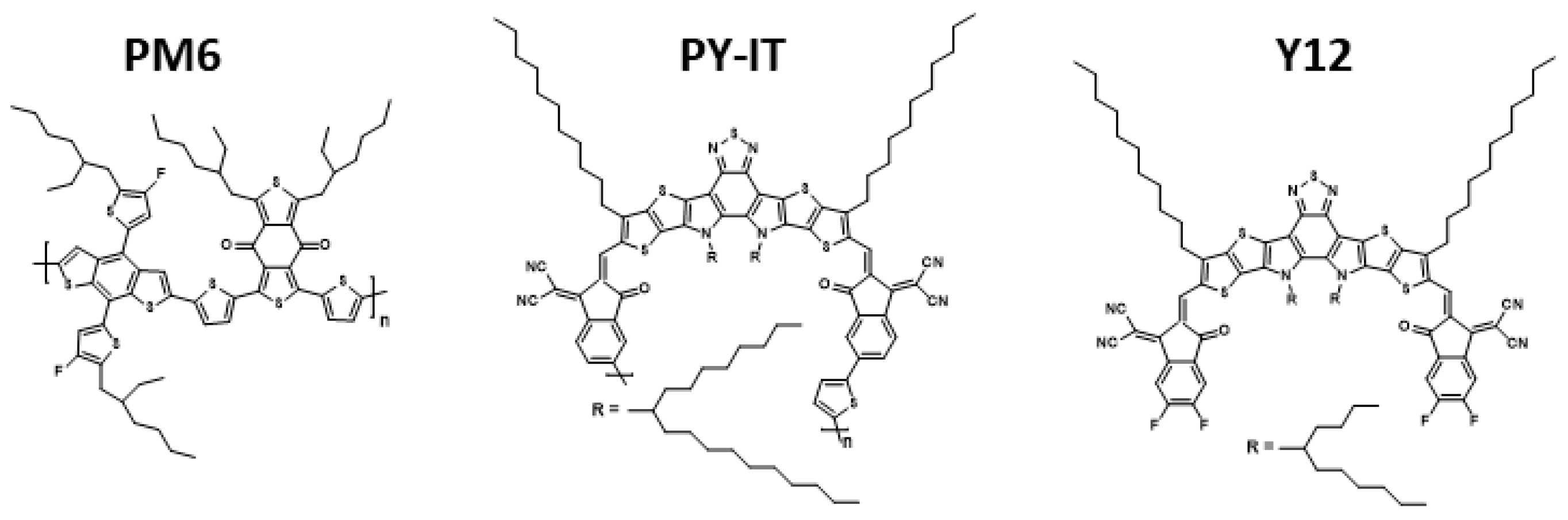
In this context, the present study focuses on the morphological characterization of such high-performance organic semiconductors and their blends, analyzing both neat materials and multi-component systems. Specifically, we investigate PM6 acting as the electron-donating polymer, the small-molecule Y12, and the polymer PY-IT as NFAs (Figure 1). PM6 is a widely utilized donor polymer, noted for its strong absorption in the visible spectrum and its ability to form ordered domains when blended with acceptors such as NFAs. Inks formulated from binary blends of PM6:Y12 and PM6:PY-IT, as well as the ternary blend PM6:PY-IT:Y12 in o-xylene, were prepared and deposited as active layers in OSCs using doctor-blade coating under ambient conditions in air. All individual materials (PM6, PY-IT, Y12) were systematically characterized using Fourier transform infrared (FTIR) and Raman spectroscopy to confirm their chemical structure and composition prior to device fabrication. Optical properties, both in solution and in thin films of the neat materials and their blends, provided a systematic characterization of their light-harvesting capabilities and spectral complementarity, which are critical for understanding and optimizing exciton generation and device performance up to 12.04% and 12.17% for PM6:PY-IT and PM6:PY-IT:Y12, respectively. The PM6:Y12 blend was used as a reference for a blend with a small-molecule NFA, Y12, to highlight the impact of this combination on device performance. Notably, all devices were fabricated with an active area of 0.25 cm2, which is four times larger than the active area typically reported in the literature, underscoring the robustness and scalability of the device performance [31,32]. This study systematically investigates the morphology of blends using advanced techniques as atomic force microscopy (AFM) and grazing-incidence wide-angle X-ray scattering (GIWAXS) to uncover the molecular and nanoscale factors influencing film formation and device efficiency, providing valuable guidelines for designing next-generation organic optoelectronic systems.

2. Materials and Methods

Materials. Indium tin oxide (ITO)-coated glass substrates, measuring 25 mm by 25 mm and featuring 15 Ω/sq resistance, were sourced from Lumtec, Taiwan. o-Xylene (C6H4(CH3)2, anhydrous 97%) and analytical standard 1,2,3,4-tetrahydronaphthalene (Tetralin) were procured from Sigma-Aldrich (Merck, Darmstadt, Germany), Saint-Quentin-Fallavier, France. PM6 (Mw~125–150 kDa, PDI~2.5) and Y12 came from 1-Material, and PY-IT was obtained from Solarmer (Mw = 18 kDa, purity > 99%). PEDOT:PSS (CLEVIOSTM AI 4083) and PDINN (purity > 98%) were supplied by Ossila. Ag (purity 99.99%) was purchased from Kurt J. Lesker Company, Dresden, Germany. All commercially available materials were utilized as received and kept under a nitrogen environment.
Ink formulation and preparation. Binary blend inks of PM6:Y12 and PM6:PY-IT were dissolved in o-xylene with 3.5% (v/v) Tetralin. For PM6:Y12, a 1:1.2 donor:acceptor ratio and a concentration of 20 mg·mL−1 were used; for PM6:PY-IT, a 1:1 ratio with 15 mg·mL−1 concentration was applied. A ternary blend of PM6:PY-IT:Y12 was dissolved in o-xylene with 3.5% (v/v) Tetralin, using a 1:1:0.2 ratio and 20 mg·mL−1 total concentration. Inks were finalized using a previously reported, carefully optimized protocol [33].
Thin films deposition. Using static blade-coating at room temperature in air, the PM6:Y12, PM6:PY-IT, and PM6:PY-IT:Y12 active layers were deposited at various sweep speeds. Blade-coating was performed with a Coat-Master 510 from Erichsen (Valence, France), equipped with a microprocessor-controlled film applicator and a drying time recorder for precise process control. For the OPV-specific layers, sweep speeds of 0.6–1.9 mm/s were used, resulting in active layer thicknesses of 88–100 nm, respectively. The coating gap was set to 60 μm, with an ink volume of 30 μL applied for all blends. Post-deposition, the active layers were annealed in air at 100 °C for 5 min.
Characterizations. FTIR spectra were recorded using a PerkinElmer Spectrum 100 spectrometer (PerkinElmer Company, Shelton, CT, USA). Raman measurements were carried out using a HR800-UV Horiba-Jobin Yvon spectrometer (Horiba Company, Vénissieux, France) equipped with an Olympus metallographic microscope (Evident Europe GmbH Company, Hamburg, Germany). The samples were excited with the red line of a He-Ne laser (λ = 632.8 nm). Prior to each measurement, the spectrometer was calibrated using a monocrystalline silicon wafer, with the Si-Si vibrational mode at 520.7 cm−1 serving as the reference. UV-Vis-NIR absorption spectra of the active layers were measured with a Cary 5000 spectrophotometer (Agilent Company, Santa Barbara, CA, USA). NMR data was recorded at 298 ± 3 K on a Bruker Avance NEO nanobay 400 MHz spectrometer (Bruker Company, Wissembourg, France), CDCl3 was used as a deuterated solvent. A Bruker DEKTAK XT stylus profilometer (Bruker Company, Wissembourg, France), with a 1 mg tip force, was used to measure the thickness of the films. AFM analysis of the blend layer surfaces was performed at ambient conditions with a Park XE-100 (Park Systems Company, Orsay, France), using tapping mode and silicon tips (MikroMash) having a theoretical resonant frequency of 300 kHz.
High-brightness synchrotron radiation at BL19B2, SPring-8 (Sayo, Japan), was employed to analyze the thin films. GIWAXS was carried out with a PILATUS 300K 2D X-ray detector (Dectris Japan K.K., Hyogo, Japan). The X-ray wavelength and incident angle were 0.100 nm and 0.13°, respectively, and crystal coherence lengths were determined via the Scherrer equation [34]:
τ = K λ β c o s θ
where τ represents the size of the ordered (crystalline) domains, which may be equal to or smaller than the grain size, and is defined as the crystal coherence length (CCL). K is a dimensionless shape factor, typically close to unity; in most cases, K ≈ 0.9 [35]. λ denotes the X-ray wavelength, β is the full width at half maximum (FWHM) of the diffraction peak in radians after correcting for instrumental broadening, and θ is the Bragg angle. Analytically, the FWHM was used to estimate the spatial extent over which ordered regions, such as crystallites, coherently diffract or scatter, according to the Scherrer equation.
Solar Cells. Devices were fabricated in the conventional OPV structure ITO/PEDOT:PSS/active layer/PDINN/Ag. The preparation of the various layers was carried out following a procedure detailed in a previous study [33]. PDINN was dissolved at 1 mg.mL−1 in methanol and spin-coated at 3000 rpm inside a glovebox to serve as hole transporting layer (HTL). A 100 nm Ag upper electrode was deposited by thermal evaporation in the glovebox at 2 × 10⁻⁶ mbar, with a shadow mask defining a device area of 0.25 cm2. EQE measurements were conducted following a previously reported setup [33].

3. Results

3.1. Physicochemical Characterization of Neat Materials

Understanding the molecular structure and chemical composition of organic semiconductors is essential for correlating their intrinsic properties with device performance. In this work, the electron-donating polymer PM6 and the non-fullerene acceptors PY-IT and Y12 were investigated using complementary spectroscopic techniques. Due to the poor solubility of the polymeric materials, NMR analysis could only be performed on the small-molecule compound Y12. The obtained NMR spectrum (Figure S1) is in good agreement with previously reported data in the literature [36]. Consequently, the structural characterization of the polymers was carried out using FTIR and Raman spectroscopy measured in thin-film form. These techniques enable verification of the molecular structure, identification of functional groups and bonding motifs, and evaluation of backbone integrity and side-chain incorporation.
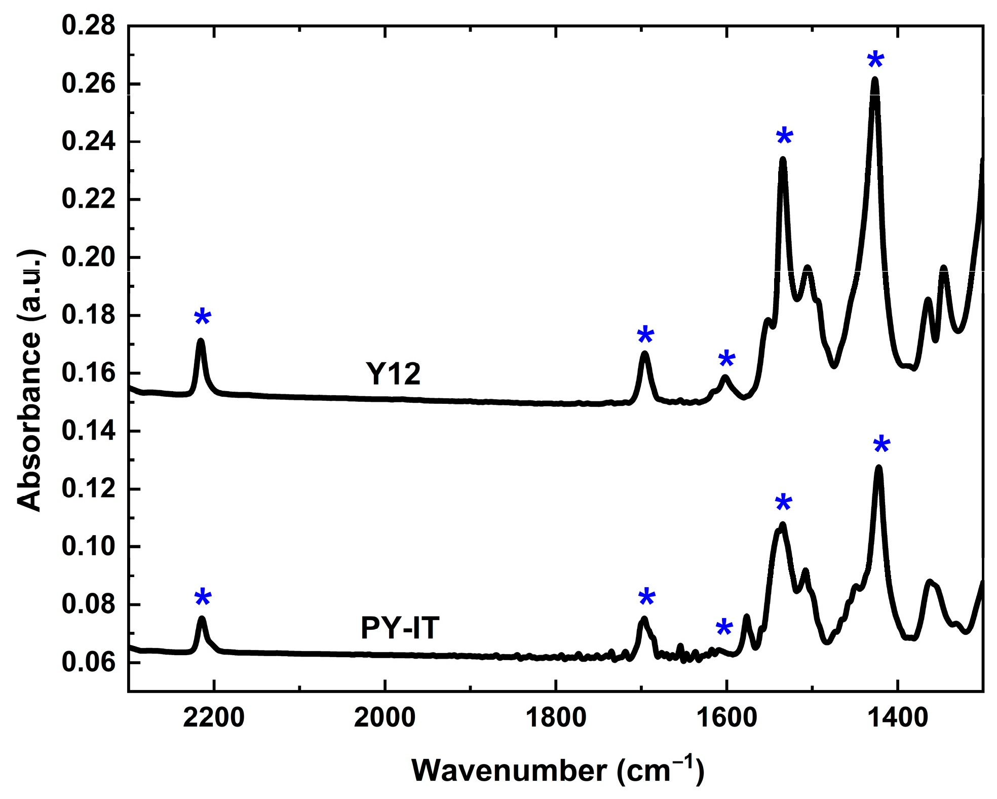
Figure 2 presents the FTIR absorption spectra of both NFAs, Y12, and PY-IT. The small molecule and polymer display similar trends, characterized by peaks at 2215 cm−1, 1696 cm−1, 1602 cm−1, 1534 cm−1 and 1422 cm−1. Compared to Y6, Y12 exhibits only a minor difference in the alkyl side chain on the central core (Y6 has a 2-ethylhexyl chain, while Y12 has a 2-butylhexyl chain); nevertheless, the observed peaks remain consistent with those reported for Y6 in the literature [37]. The peaks at 1602 cm−1 correspond to the C=N stretching vibration of the fused benzothiadiazole aromatic core, while the C≡N stretching mode appears at 2215 cm−1. The peaks at 1534 cm−1 are attributed to the malononitrile moieties, dominated by C-C vibrations, and the C=C stretching mode of the conjugated plane is observed at 1422 cm−1. The peaks at 1696 cm−1 are assigned to the unsaturated carbonyl stretching vibrations (C=O) of the terminal groups. The correspondence of the FTIR peaks indicates that the polymer and small molecules share the same vibrational signatures, reflecting similar functional groups and bonding motifs in their molecular frameworks, thereby confirming the expected chemical structure of the backbone in Y12 and PY-IT. In comparison, the FTIR spectrum of PM6 exhibits characteristic vibrational features associated with its conjugated backbone and alkyl side chains, consistent with its donor polymer structure [38,39]. The ester carbonyl (C=O) stretching is observed around 1700–1720 cm−1, confirming the presence of electron-withdrawing ester groups in the polymer backbone. The conjugated aromatic and vinylene units give rise to C=C stretching vibrations near 1600 cm−1, and C-H bending modes from both the aromatic rings and alkyl chains appear in the 1450–1400 cm−1 region. Overall, the spectrum confirms the expected chemical structure of PM6, with clear signatures of its conjugated backbone, ester functionalities, and side chains, which are essential for its optoelectronic performance.
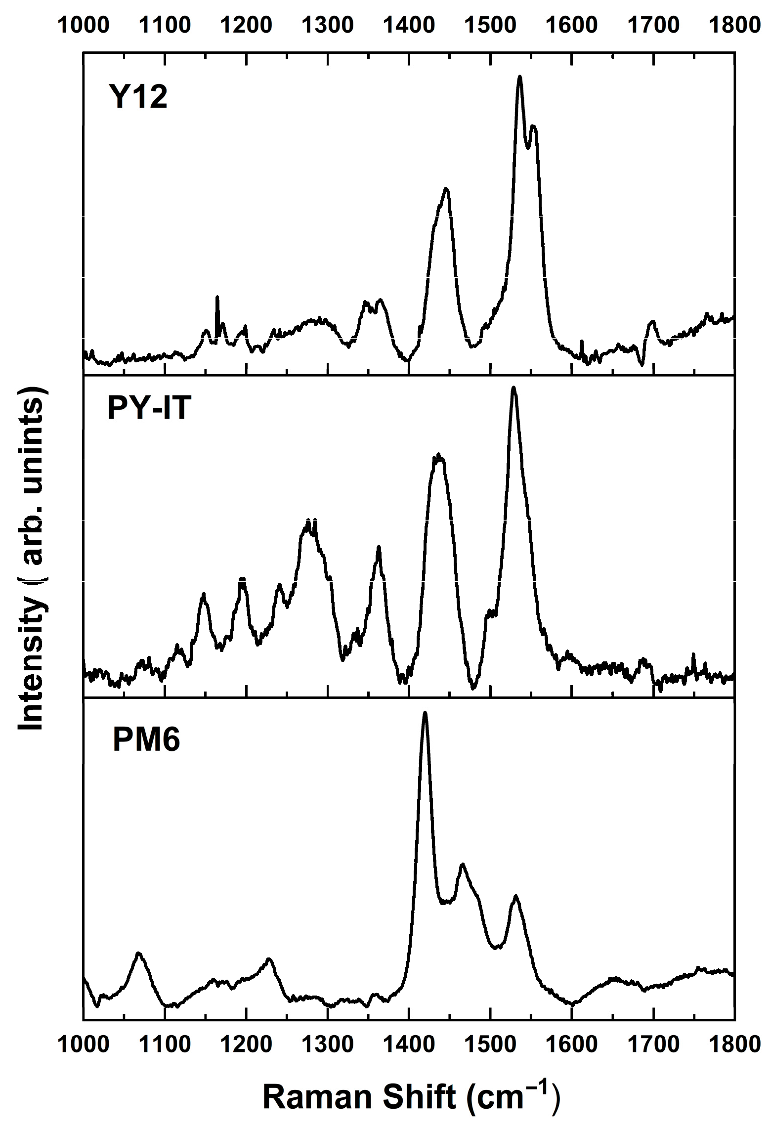
Raman spectroscopy was employed to complement the FTIR analysis. As shown in Figure 3, all three films exhibit well-resolved vibrational features. The Raman spectrum of PM6 displays characteristic peaks in the 1400–1600 cm−1 range [40]. The prominent peak at 1420 cm−1 is assigned to thiophene ring stretching, while the peak at 1467 cm−1 arises from coupled thiophene backbone stretching and delocalized vibrational modes of the aromatic BDT core. A higher-frequency peak at 1532 cm−1 corresponds to vibrations of the BDT backbone, involving symmetrical benzene ring stretching coupled with thiophene backbone motions. For PY-IT, the Raman spectrum obtained is consistent with previous reports in the literature [41]. The main peaks can be attributed to overlapping vibrational modes: the band at 1529 cm−1 corresponds to symmetric C=C stretching of C=C bonds attached to the five-membered carbon rings; the peak at 1500 cm−1 arises from asymmetric C–C and C–N stretching within the central pyrrole units; and the feature at 1436 cm−1 is assigned to asymmetric C–C stretching of the thiophene units. Lower-intensity peaks in the 1000–1200 cm−1 region are likely due to collective distortions of entire rings or fused-ring groups, as well as C–S stretching within thiophene rings. For Y12, although this material has not been extensively characterized in the literature, most observed peaks correspond closely to the principal vibrational modes reported for the Y-family acceptors [41,42], suggesting similar backbone and side-chain vibrational behavior.
Overall, the combined FTIR and Raman analyses confirm that PM6, PY-IT, and Y12 possess the expected chemical structures and well-defined vibrational signatures. These results provide a solid structural foundation for interpreting their optical properties, nanoscale morphology, and photovoltaic performance in subsequent studies.

3.2. Optical Properties in Solution

Figure 1 displays the molecular structures of PM6, PY-IT and Y12. PM6 exhibits an alternating copolymer structure, consisting of two repeating conjugated units: (i) a donor unit based on benzo[1,2-b:4,5-b′]dithiophene (BDT) and (ii) an acceptor unit derived from benzodithiophene-dione (BDD). The polymer backbone alternates between BDT and BDD units in a repeating push–pull (D-A) configuration. This design yields in a planar and extended π-conjugated backbone, allowing efficient π-π stacking between polymer chains. Both Y12 and PY-IT are characterized by a distinctive “Y-shaped” or “V-shaped” molecular architecture. They feature a rigid, fused conjugated central core, specifically 2,2′-bithiophene-fused benzothiadiazole (BTD), with alkyl side chains to improve solubility and promote favorable molecular packing in thin films. This central core plays a critical role in promoting π-π stacking and strong intermolecular interactions, which play a crucial role in controlling the layer morphology. Additionally, PY-IT exhibits a more linear and extended structure, incorporating thiophene units along its backbone to further enhanced conjugation.
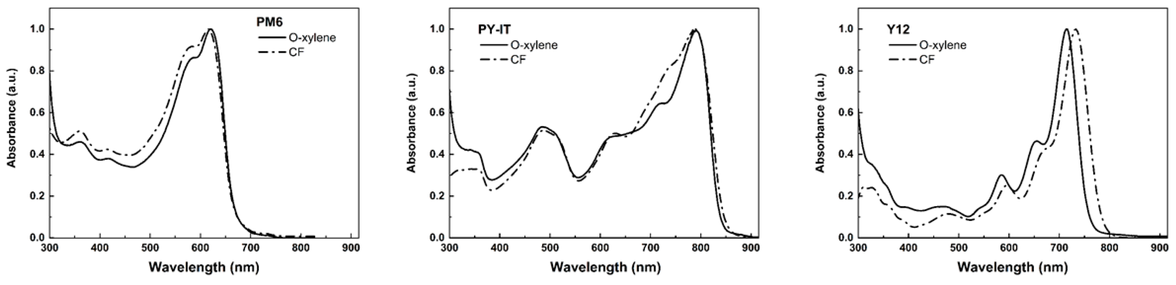
Normalized UV–Vis spectra of the neat materials in diluted o-xylene and chloroform (CF) solution are displayed in Figure 4. Table S1 gives the characteristic peaks of the neat materials in solution, while Table S2 lists the band/peak position with their corresponding assignment. Materials were highly soluble in CF due to their alkyl side chains, which facilitates solution processing in chlorinated solvents. A combination of hotplate heating, magnetic stirring, and vortexing was applied to ensure optimal solubility of the materials in o-xylene [33]. PM6 shows a UV band at 350–450 nm corresponding to local π-π* transitions on its aromatic units, while its main band at 500–600 nm indicates an extended π-π* transition accompanied by moderate intramolecular charge transfer (ICT) along the polymer chain. A shoulder at 580–620 nm reflects vibronic transitions associated with high effective conjugation. A moderate bathochromic shift in o-xylene (peak maximum at 616 nm in CF and 621 nm in o-xylene) highlights more stretched chains with increased conjugation. In CF solution, Y12 and PY-IT exhibited their main absorption peaks at longer wavelengths, 733 nm for Y12 and 788 nm for PY-IT, respectively. Compared to PM6, Y12 and PY-IT display strong absorption in the near-infrared (NIR) region. The difference in main absorption peaks for Y12 in CF (733 nm) and o-xylene (715 nm), as well as the constant absorption peak for PY-IT at 788 nm regardless of the solvent, can be explained by several factors related to molecular size and solvent interactions. Y12 exhibits a UV band at 400–500 nm due to local π-π* transitions on terminal aromatic units, and a broad main band from 650 to 850 nm resulting from dominant ICT, indicating strong electron transfer between donor and acceptor moieties. The absorption maximum around 780–820 nm corresponds to the S0→S1 transition, reflecting a small optical gap. PY-IT displays a UV band at 350–450 nm for local π-π* transitions, while its main band between 600 and 900 nm demonstrates very intense ICT, suggesting extensive electronic delocalization across the molecule; its absorption edge above 850 nm corresponds to low-energy transitions, consistent with a narrow optical gap. Overall, the progression from PM6 to PY-IT highlights an increase in ICT strength and conjugation length, correlating with red-shifted absorption and enhanced charge-transfer character. Small molecules like Y12 tend to have more pronounced electronic transitions that can be affected by the solvent environment. The difference in the absorption peaks is likely due to solvent–solute interactions; for instance, CF is more polar than o-xylene, and polar solvents typically cause a redshift by stabilizing the excited state of the molecule. In contrast, the polymeric structure of PY-IT reduces its sensitivity to solvent effects, resulting in a consistent absorption profile across different solvents. The conjugation and flexibility of the molecule influence how the absorption peak shifts in different solvents. Therefore, the size, structure, and solvation effects on Y12 contribute to the observed spectral changes, while PY-IT remains unaffected due to its molecular characteristics. Another notable difference is the bandwidth: PY-IT exhibits a broader absorption band compared to Y12, reflecting the polymer’s conformational disorder versus the higher rigidity of Y12.
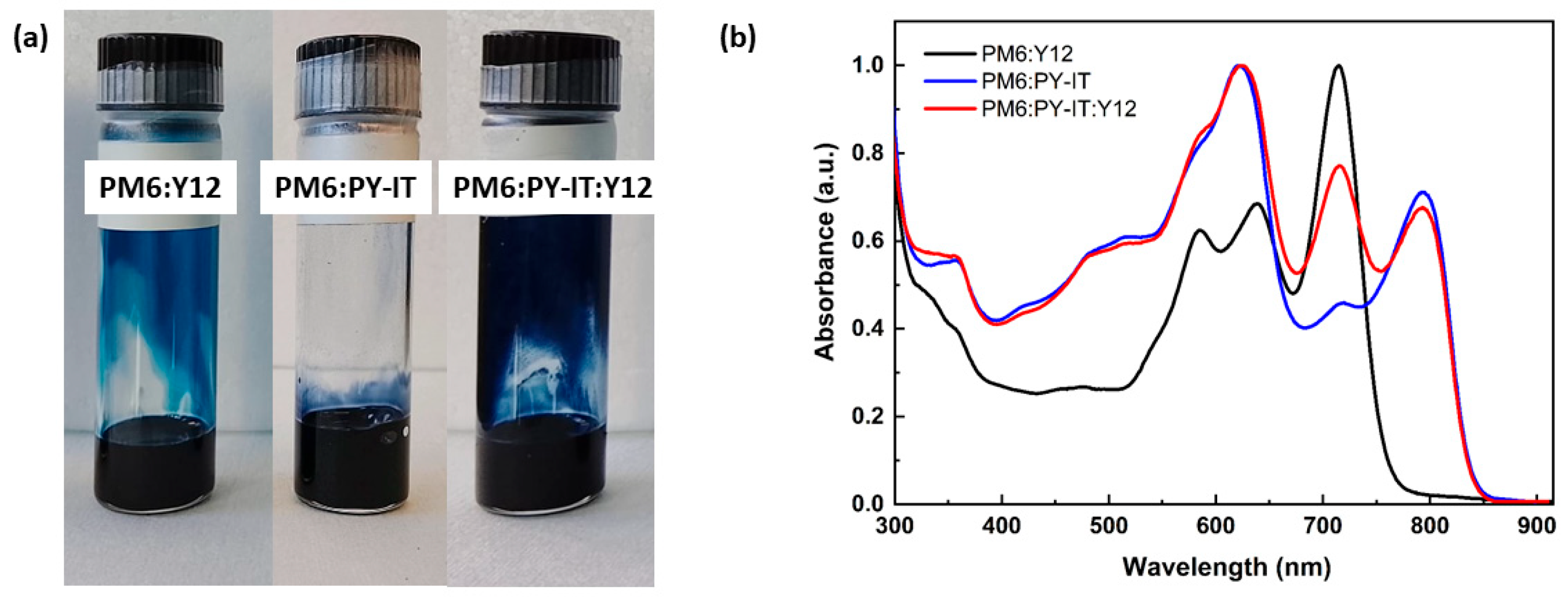
Figure 5a shows a photograph of the three o-xylene-based inks: PM6:Y12, PM6:PY-IT, and PM6:PY-IT:Y12. To ensure a consistent comparison, the same three steps in ink formulation, hotplate heating, magnetic stirring, and vortex mixing were applied to all three blends [33]. The images indicate that the inks are homogeneous and free from any visible aggregates in solution, a critical prerequisite for achieving a uniform and effective film formation through doctor blade coating. In solution, PM6:Y12, PM6:PY-IT, and PM6:PY-IT:Y12 exhibited distinct primary absorption bands, reflecting the characteristic signatures of the materials present in each blend (Figure 5b). Table S1 gives the characteristic peaks of the blends in solution compared to neat materials. PM6:Y12 exhibits a well-defined absorption profile, featuring a twisted, structured first peak around 600 nm. The spectrum reveals a prominent maximum at 585 nm, assigned to Y12, and a second peak at 639 nm, attributed to PM6. The most intense absorption feature, located at 715 nm, is directly assigned to Y12, in line with the PM6:Y12 ratio of 1:1.2 which favors the absorption of Y12 due to its higher content in the blend. In blends containing PY-IT, the absorption extends up to 800 nm. PM6:PY-IT exhibits two distinct absorption peaks: one at 621 nm, attributed to PM6, and another at 795 nm, assigned to PY-IT. It is noteworthy that the spectrum of the ternary PM6:PY-IT:Y12 blend exhibits three distinct absorption peaks, each corresponding to the dominant contributions of the individual materials in the blend (623 nm to PM6, 715 nm to Y12 and 793 nm to PY-IT). Consequently, the absorption spectrum of this ternary blend exhibits a more continuous absorption profile across the entire visible range, with an extension into the NIR region, thereby enhancing its overall light-harvesting capability.

3.3. Optical Properties in Thin Films

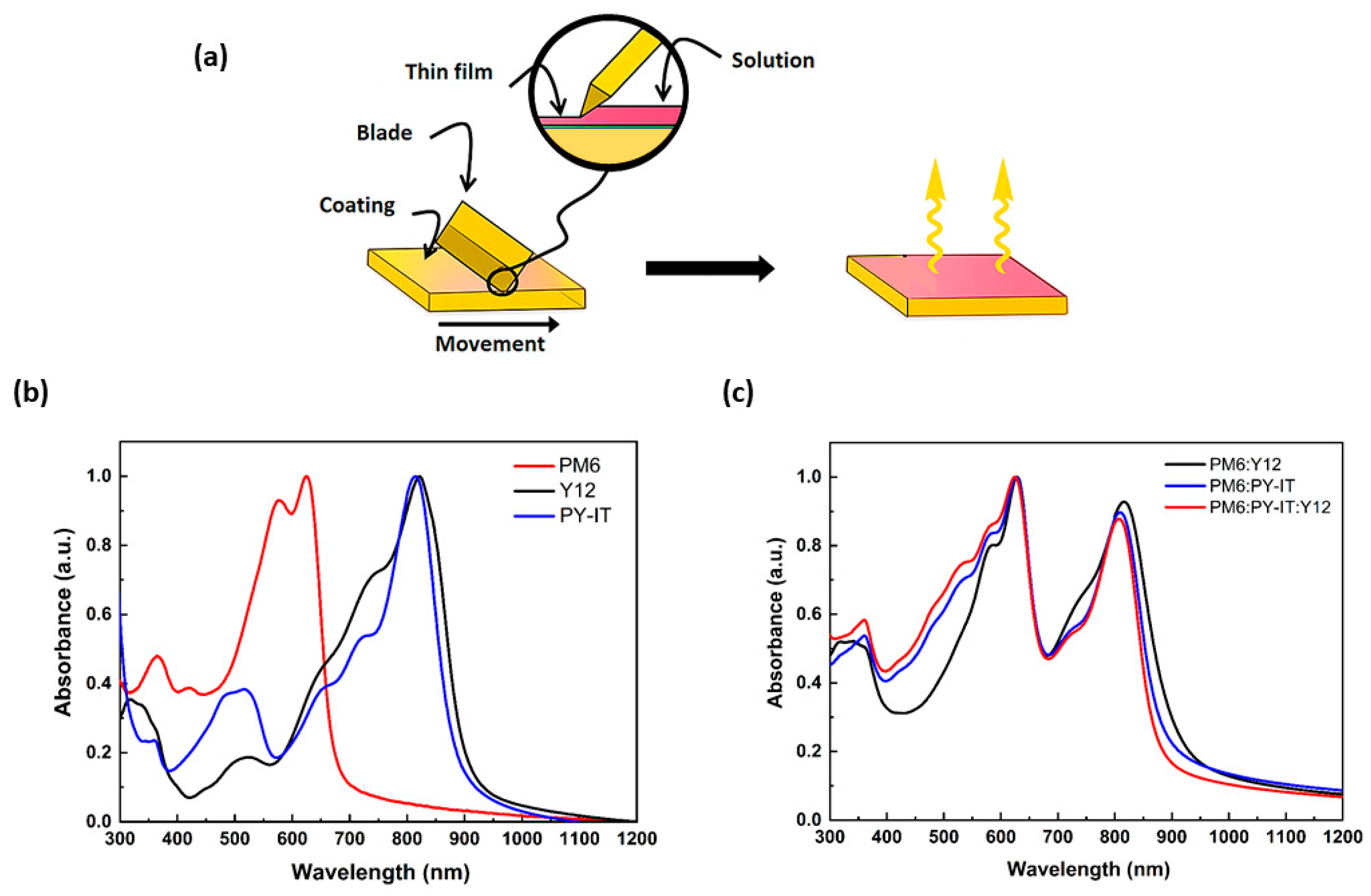
Using a doctor-blade coater, thin films of the blend solutions in o-xylene were deposited under ambient conditions (Figure 6a). To ensure consistent film quality, parameters including blade height, coating speed, and solution concentration were carefully optimized. Finally, the films were annealed on a hot plate at 100 °C for 5 min to ensure complete solvent removal and uniform film formation. Figure 6b illustrates the UV–Vis absorption spectra, normalized, of the neat materials in thin films. Table S1 gives the characteristic peaks of the neat materials in film. The absorption of PM6 is primarily observed in the 450–700 nm range, while Y12 absorbs mainly between 600 and 950 nm, with a peak at 821.5 nm. As a polymerized Y derivative, PY-IT exhibits absorption predominantly between 600 and 950 nm, reaching a maximum at 814 nm and covering the NIR region. Notably, when transitioning from solution to film, both Y12 and PY-IT show significantly red-shifted peaks, which suggests the occurrence of π-π interactions between molecules and ordered aggregation in the solid state. The pronounced vibronic features provide strong evidence of enhanced molecular ordering and aggregation in the solid-state films. While a moderate spectral broadening is observed for both PM6 and PY-IT films upon transitioning from solution to thin film, Y12 displays a pronounced broadening of approximately 150 nm, reflecting strong π–π stacking and intermolecular interactions among its rigid conjugated backbones.
Figure 6c displays the normalized thin-film spectra of the PM6:Y12, PM6:PY-IT and PM6:PY-IT:Y12 blend films. Despite variations in the D:A ratio, the absorption characteristics of the acceptor component are almost unchanged across the 750–950 nm range in all three blend films. The PY-IT-based inks, including PM6:PY-IT and PM6:PY-IT:Y12 blends, show slightly enhanced absorption between 450 and 550 nm, displaying clear spectral features typical of the PY-IT polymer (Figure S2). Additionally, the well-defined spectral features observed in the blends matched exactly those of the neat materials, confirming that each component, particularly PY-IT, dissolves properly in o-xylene, yielding a homogeneous and well-mixed blend (Figure S2). As for the absorption spectra of the solution-based blends, the first peak around 625 nm (PM6:Y12: 629 nm, PM6:PY-IT: 627 nm and PM6:PY-IT:Y12: 624 nm) is primarily attributed to the absorption of PM6, while the second peak, located toward the NIR region (PM6:Y12: 816 nm, PM6:PY-IT: 809 nm and PM6:PY-IT:Y12: 807 nm) is associated with the acceptor materials (Table S1). Compared to the neat films, the absorption maxima in the blend films have shifted slightly, to longer wavelengths (by 3–5 nm) for the PM6 peak and to shorter wavelengths (by 5–7 nm) for Y12 and PY-IT peaks. The shift in absorption maxima observed in the blended film can be attributed to the molecular interactions between the components in the blend [43]. The slight red shift in the absorption maximum of PM6 suggests that the presence of Y12 and PY-IT induces some degree of interaction or reorganization in the PM6 molecular structure, potentially leading to a lowering of the electronic energy levels and thus a shift to longer wavelengths. On the other hand, the slight blue shift observed for Y12 and PY-IT in the blend indicates that these molecules are likely experiencing interactions with the PM6 component that increase their electronic energy levels, which could lead to a shift in the absorption maxima to shorter wavelengths. These changes are likely due to modifications in molecular packing, π-π stacking, or other intermolecular interactions, which influence the electronic structure and optical properties, reflecting the complex interplay between blend composition, molecular organization, and intermolecular forces.

3.4. Analysis by AFM

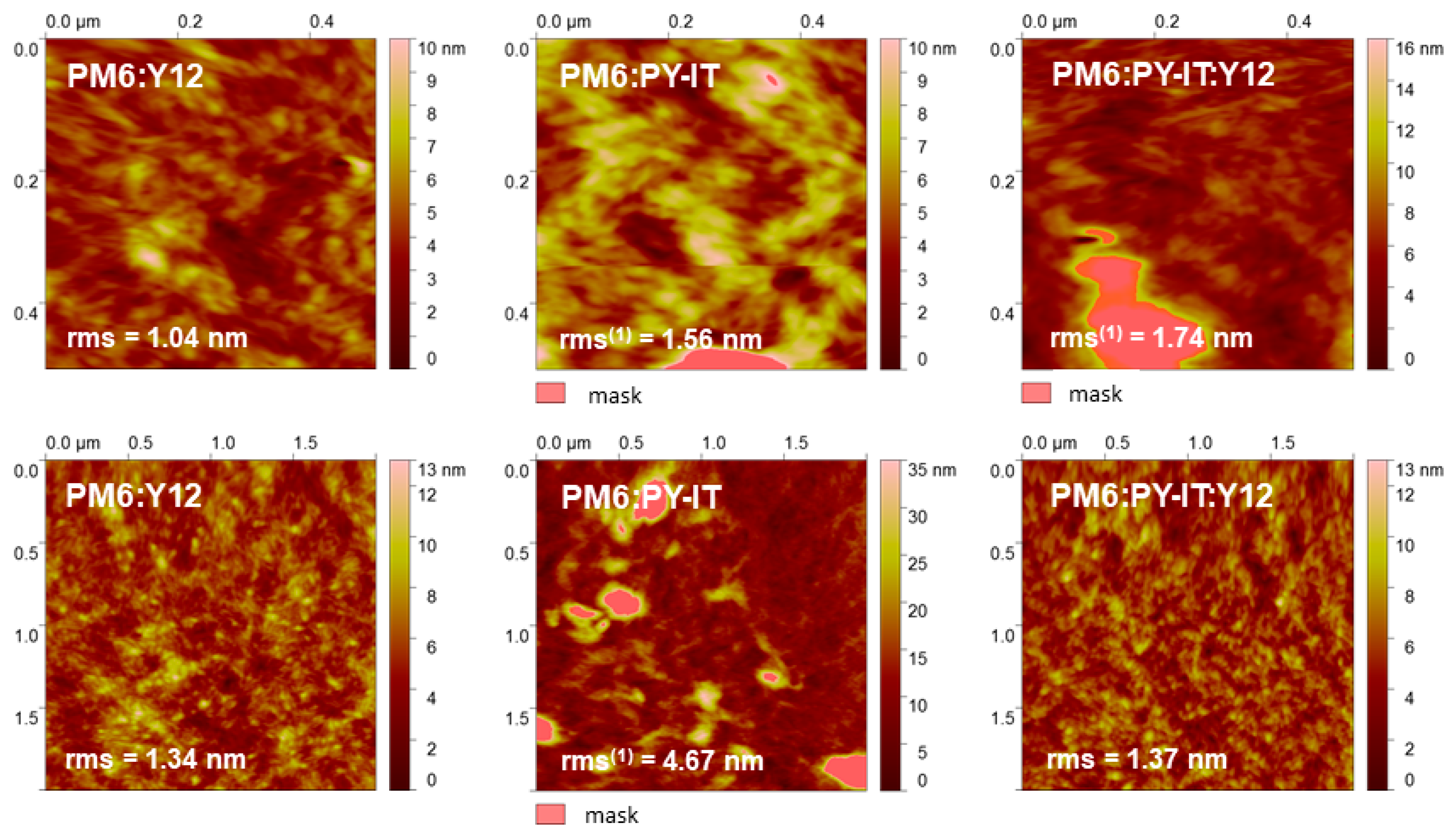
Before depositing the active layer via doctor-blade coating (Figure 6a), a PEDOT:PSS buffer layer was spin-coated onto the ITO substrate. The AFM image presented in Figure 7 reveals the surface topography of the PM6:Y12, PM6:PY-IT and PM6:PY-IT:Y12 layers with nanoscale resolution. The morphology appears relatively homogeneous, with well-defined domains distributed across the scanned area. The contrast in the image suggests differences in the local height profile, with brighter regions corresponding to elevated features and darker regions to depressions. This height variation indicates the presence of nanoscale features that contribute to the overall surface roughness. For the estimation of the root-mean-square (RMS) roughness values, higher aggregates were excluded from the calculation to avoid biasing the measurement (see Figure S3 in SI for corresponding AFM images not using the mask option).
The PM6:Y12 film exhibits relatively low and consistent roughness values, increasing slightly from 1.04 nm at 0.5 × 0.5 µm2 to 1.34 nm at 2 × 2 µm2, indicating uniformly distributed domains within a highly textured but continuous morphology. PM6 retains its distinct rice-shaped nanograin morphology within the blends [33]. For the PM6:PY-IT blend, an increase in roughness is observed (1.56 nm at 0.5 × 0.5 µm2 and 4.67 nm at 2 × 2 µm2). However, prominent bright features suggest the presence of localized aggregates or domains with substantially greater thickness, which, when included in the calculation, results in an increased RMS value (2.13 nm at 0.5 × 0.5 µm2 and 7.81 nm at 2 × 2 µm2 in Figure S3). At 2 × 2 µm2, the characteristic fine structure of PM6’s rice-shaped grains is no longer clearly resolved, representing the most significant observation. However, upon incorporating the small molecule Y12 into the ternary PM6:PY-IT:Y12 system, the distinct rice-shaped nanometer-scale grain features of PM6 are retained, suggesting that the PM6 polymer chains preserve their intrinsic organization. Additionally, at 2 × 2 µm2, a comparable RMS (1.37 nm for PM6:PY-IT:Y12 vs. 1.35 nm for PM6:Y12) is measured. Phase images reinforce this slightly more heterogeneous aspect for PM6:PY-IT blend with more noticeable phase contrast variations (Figure S4). Furthermore, the ternary film displays notable morphological changes at higher scale, including a reduced number of clusters and a significantly lower RMS (Figure S5). These observations indicate enhanced solubility and improved miscibility of the components in solution, facilitated by the presence of the small molecule Y12.

3.5. Analysis by GIWAXS

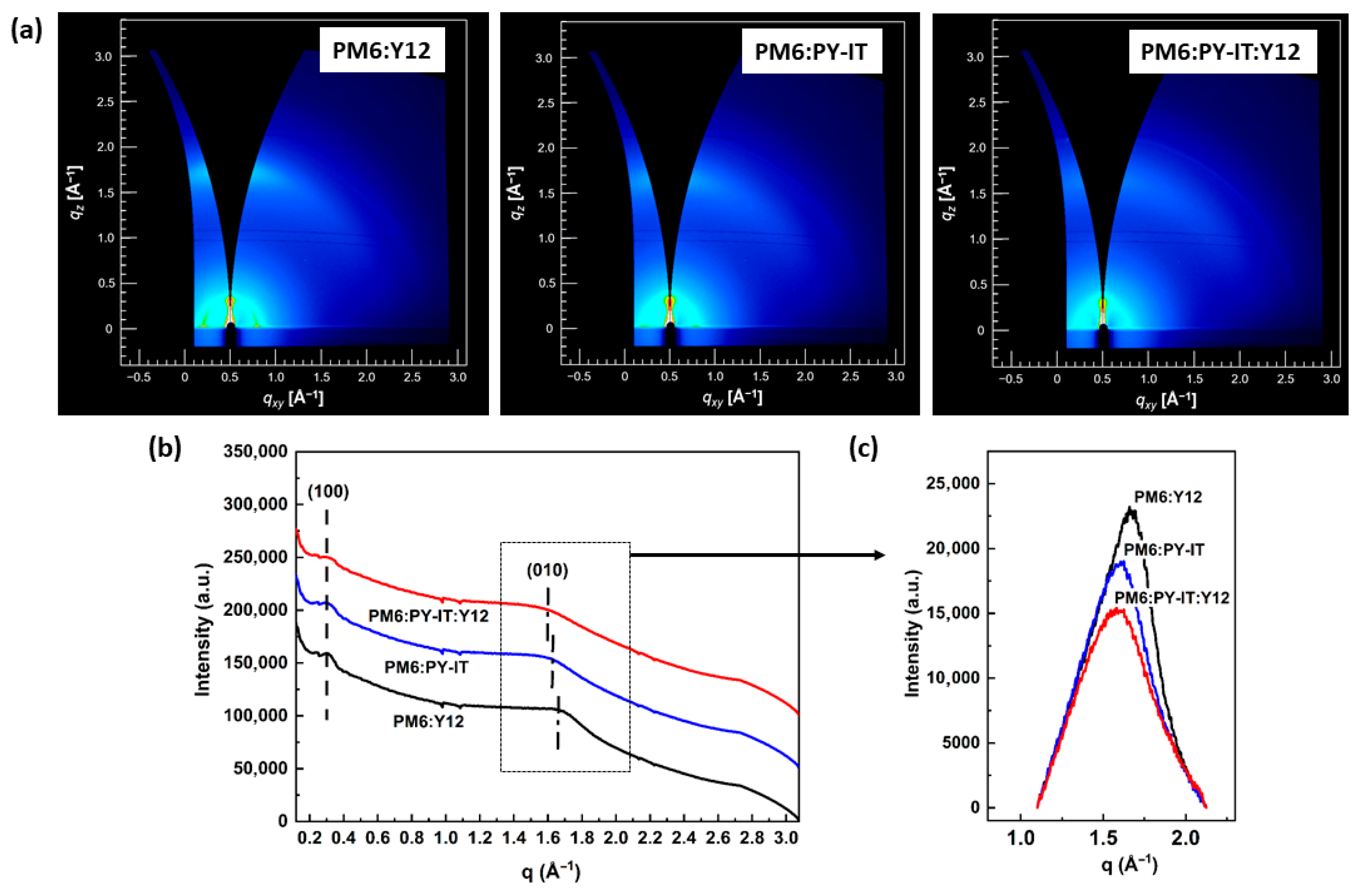
To study the crystallinity and molecular packing of the blend films, GIWAXS was employed. With a low incident angle, GIWAXS penetrates deeply into the film, providing valuable insights into thin-film morphology and structure [44]. GIWAXS measurements in this study provide insights into the nanoscale percolating networks seen in AFM. Figure 8a shows the 2D GIWAXS patterns of films based on PM6:Y12, PM6:PY-IT and PM6:PY-IT:Y12. Figure 8b displays the integrated intensities at qz as a function of qxy. The peak indexed as (100) at q = 0.30 Å−1 originates from the edge-on lamellar arrangement of PM6, exhibiting a d-spacing of 2.09 nm [33]. The (010) peaks at approximately 1.60–1.67 Å−1 relate to the diffraction peaks arising from π-π stacking of the acceptors (Y12, PY-IT), which are associated adopting a face-on orientation with respect to the substrate (Table 1). Both (100) and (010) peaks are clearly observed, highlighting the structural organization resulting from the interactions of PM6 with Y12 or PY-IT. Interestingly, the blends show a strikingly similar structural arrangement.
The (010) peaks observed at q = 1.67 Å−1, 1.62 Å−1 and 1.60 Å−1 correspond to π−π stacking distances of 3.74 Å, 3.87 Å, and 3.92 Å for PM6:Y12, PM6:PY-IT, and PM6:PY-IT:Y12 blends, respectively (Figure 8c). In the PM6:Y12 blend, the π-π stacking distance is slightly shorter, which can be attributed to Y12’s 3.54 Å spacing resulting from its simpler structure. In the PM6:PY-IT:Y12 blend, the incorporation of Y12 molecules interferes with and disrupts the organization of the PY-IT polymer chains, both near and within the PY-IT domains. This interference causes a slight distortion in the PY-IT network, leading to a modest increase in the π-π stacking distance, from 3.87 Å to 3.92 Å, compared to the PM6:PY-IT blend. The CCL, calculated by Equation (1), decreases across the blends from 1.87 nm in the PM6:Y12 blend to 1.80 nm in PM6:PY-IT, and further to 1.66 nm in the PM6:PY-IT:Y12-based ternary blend. The decrease in the CCL values from PM6:Y12 to PM6:PY-IT:Y12 blend correlates with the observed variations in π-π stacking distances, indicating that the more ordered molecular arrangement (i.e., PM6:Y12) leads to the formation of more compact and larger enriched domains.
Through GIWAXS, deeper insights into the molecular stacking and crystallinity of the nanoscale structures observed in AFM can be obtained. These observations indicate that the organic materials interact properly during ink preparation, leading to a highly optimized donor–acceptor interface.

3.6. EQE Spectral Profile

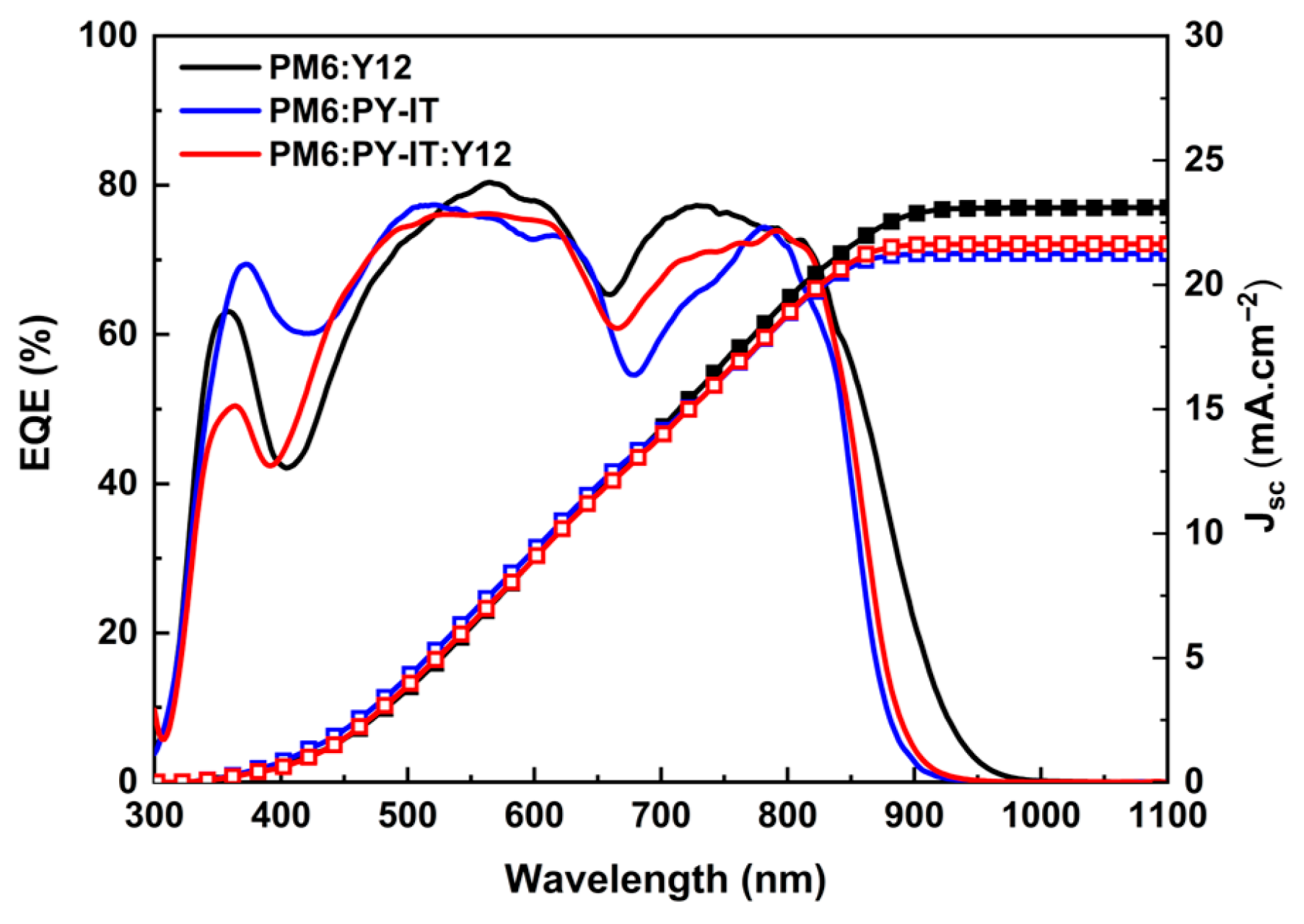
OPVs were fabricated using the conventional configuration described in the experimental part. The same batch of PM6 was used as the donor material in the fabrication of devices. The EQE spectra of the devices are shown in Figure 9. The EQE spectral profile clearly highlights the variations in efficiency across different wavelength ranges. The devices tested had an active area of 0.25 cm2. Table 2 summarizes the photovoltaic parameters, including open-circuit voltage (Voc), short-circuit current density (Jsc), fill factor (FF), and power conversion efficiency (PCE). Devices based on PM6:PY-IT and PM6:PY-IT:Y12 exhibit higher Voc values compared to PM6:Y12. This phenomenon is due to the higher LUMO level of PY-IT compared to Y12, which creates a larger energy offset with PM6’s HOMO (Figure S6). The devices exhibit wide spectral sensitivity over 350–900 nm, achieving maximum EQE values greater than 75%, reflecting their high photoelectric performance. The presence of two well-defined peaks further validates that both materials, PM6 and Y12 or PY-IT, participate in the photoelectric conversion. The peak at the shorter wavelength is primarily attributed to the absorption of PM6, with additional contributions from Y12 or PY-IT, while the second peak, as depicted in Figure 6, originates from the absorption of the NFA. As a result, the clearly defined background structural organization seen in AFM images is essential for improving PCE by effectively reducing the impact of aggregates in PY-IT-based devices (all-polymer PM6:PY-IT and ternary PM6:PY-IT:Y12 blends). As shown in Figure 6c, slight variations in the absorption spectra correspond to similar trends in the EQE spectra, emphasizing the relationship between optical absorption and device performance. Slightly enhanced absorption in the 350–550 nm region for the PM6:PY-IT and PM6:PY-IT:Y12 blends boosts EQE within the same range, while the pronounced and structured peak of PY-IT results in lower EQE in the 700–800 nm region. However, this is partially compensated by a higher EQE intensity in the PM6:PY-IT:Y12 blend, which brings its EQE profile closer to that of the PM6:Y12 blend. This effect is also evident in the integrated JSC values with 21.25 mA.cm−2 and 21.65 mA.cm−2 for the PM6:PY-IT and PM6:PY-IT:Y12-based devices, respectively (Table 2). A higher Jsc values of 23.09 mA.cm−2 for the PM6:Y12-based device can be ascribed to a nearly square EQE spectrum between 400 and 900 nm. This characteristic is considered ideal for improving the overall efficiency of OSCs. The integrated Jsc values are within 6% of the measured values, demonstrating a high level of consistency and confirming the accuracy of the experimental data. In the ternary blend, the EQE profile evolves further toward a flat, broad-spectrum response, leading to even higher performance. Although not prominent visible in the absorption spectrum of the ternary blend, Y12 likely contributes to enhancing light absorption over a wider range of wavelengths, thereby improving spectral efficiency.

4. Conclusions

This study provides a detailed investigation of the molecular structures, chemical and optical properties, and film morphologies of the polymer donor PM6 and non-fullerene acceptors PY-IT and Y12. The well-designed structures of both the polymer and small molecules enable efficient light absorption across a broad range of wavelengths. The blend films were prepared using doctor-blade coating techniques in air, employing non-halogenated o-xylene as the solvent. This approach ensured uniformity and homogeneity of the films, producing high-quality active layers suitable for OSC devices. The absorption spectra and AFM images demonstrate the effective blending of PM6, PY-IT, and Y12, resulting in favorable molecular ordering, π-π stacking, and enhanced light-harvesting capabilities within the active layers. The incorporation of Y12 in the ternary blend improves the miscibility of the two polymers, facilitating the formation of more homogeneous films on a large scale. This, in turn, enables the fabrication of OSCs with comparable performance to those based on binary blends with PCE of 12%, but with a slightly broader spectral signature due to enhanced absorption in the NFA region. Further insights into the films’ molecular arrangement and crystallinity were gained through GIWAXS analysis, revealing a correlation between molecular arrangement and overall morphology. The combination of morphological observations from AFM and GIWAXS with the excellent photon conversion efficiencies indicated by the EQE spectra highlights the importance of controlling film structure to optimize OSC performance. Additionally, ternary PM6:PY-IT:Y12-based devices offer a promising strategy to achieve a nearly square EQE spectrum between 400 and 900 nm, extending the absorption range.

Supplementary Materials

The following supporting information can be downloaded at https://www.mdpi.com/article/10.3390/physchem6010012/s1, Table S1: Characteristic peaks of the neat materials and blends in solution and in films; Table S2: Spectral analysis of PM6, Y12 and PY-IT in solution; Figure S1: NMR spectrum of Y12; Figure S2: (a) Normalized absorption spectra of PM6 (grey), PY-IT (blue) and PM6:PY-IT (blue line) thin films. (b) Normalized absorption spectra of PM6 (grey), PY-IT (blue) and PM6:PY-IT:Y12 (red line) thin films; absorption spectra of Y12 (orange) is given proportional to a ratio 0.2 compared to 1 for PM6 and PY-IT. Dashed lines are used as visual guides to indicate the peak positions corresponding to the material structures; Figure S3: AFM topography images of PM6:Y12, PM6:PY-IT and PM6:PY-IT:Y12 blends; Figure S4: AFM phase images of PM6:Y12, PM6:PY-IT and PM6:PY-IT:Y12 blends. Figure S5: AFM topography and phase images of PM6:Y12, PM6:PY-IT and PM6:PY-IT:Y12 blends. RMS(1) indicates the roughness value using the mask, and RMS the value without the mask. Figure S6: Energy levels of PM6, PY-IT and Y12.

Author Contributions

Conceptualization, C.V.-A. and C.M.R.H.; methodology, C.V.-A.; validation, C.V.-A., C.M.R.H. and M.e.A.K.; investigation, M.e.A.K., A.K., T.W., H.S. and S.D.; resources, C.V.-A., J.A., O.M., G.Q. and C.M.R.H.; data curation, C.V.-A., M.e.A.K., J.A. and O.M.; writing—original draft preparation, C.V.-A.; writing—review and editing, C.V.-A., G.Q. and J.A.; visualization, C.V.-A.; supervision, J.A., C.V.-A. and C.M.R.H.; project administration, C.V.-A.; funding acquisition, J.A. and C.V.-A. All authors have read and agreed to the published version of the manuscript.

Funding

This research was funded by the French Research Agency (ANR, project ANR-22-CE06-0018, MONOPOLY) and has received funding from the European Union’s Horizon Europe research and innovation programme under the Marie Skłodowska-Curie grant agreement No. 101169056.

Data Availability Statement

The data are contained within the article.

Acknowledgments

C.V.-A., J.A., O.M., G.Q., C.M.R.H. and M.e.A.K. gratefully acknowledge the financial support from the French Research Agency (ANR, project ANR-22-CE06-0018, MONOPOLY). C.V.-A., J.A., O.M., and A.K. also express their sincere gratitude to the European Research Executive Agency (REA) for funding through the Marie Skłodowska-Curie Actions Doctoral Networks under the MENTOR project (grant number 101169056). The synchrotron radiation experiments were performed at BL19B2 in Spring-8 with the approval of the Japan Synchrotron Radiation Research Institute (JASRI) (Proposal No. 2018A2065). C.V.A. expresses her special thanks to Noriyuki Yoshimoto for setting up the collaboration for GIWAXS experiments.

Conflicts of Interest

The authors declare no conflicts of interest. The funders had no role in the design of the study; in the collection, analyses, or interpretation of data; in the writing of the manuscript; or in the decision to publish the results.

Abbreviations

The following abbreviations are used in this manuscript:
PEDOT:PSSPoly(2,3-dihydrothieno-1,4-dioxin)-poly(styrenesulfonate)
ITOIndium tin oxide
Y52,2′-((2Z,2′Z)-((12,13-bis(2-ethylhexyl)-3,9-diundecyl-12,13-dihydro-[1,2,5]thiadiazolo[3,4-e]thieno[2″,3″:4′,5′]thieno[2′,3′:4,5]pyrrolo[3,2-g]thieno[2′,3′:4,5]thieno[3,2b]indole-2,10-diyl)bis(methanylylidene))bis(3-oxo-2,3-dihydro-1H-indene-2,1-diylidene))-dimalononitrile
PM6Poly[(2,6-(4,8-bis(5-(2-ethylhexyl)-4-fluorothiophen-2-yl)-benzo[1,2-b:4,5-b′]dithiophene))-alt-(5,5-(1′,3′-di-2-thienyl-5′,7′-bis(2-ethylhexyl)benzo[1′,2′-c:4′,5′-c′]dithiophene-4,8-dione))]
Y122,2′-((2Z,2′Z)-((12,13-bis(2-butyloctyl)-3,9-diundecyl-12,13-dihydro-[1,2,5]thiadiazolo[3,4-e]thieno[2″,3″:4′,5′]thieno[2′,3′:4,5]pyrrolo[3,2-g]thieno[2′,3′:4,5]thieno[3,2-b]indole-2,10-diyl)bis(methanylylidene))bis(5,6-difluoro-3-oxo-2,3-dihydro-1H-indene-2,1-diylidene))dimalononitrile
PY-ITPoly[[12,13-bis(2-octyldodecyl)-12,13-dihydro-3,9-diundecylbisthieno[2″,3″:4′,5′]thieno[2′,3′:4,5]pyrrolo[3,2-e:2′,3′-g][2,1,3]benzothiadiazole-2,10-diyl]methylidyne[1-(dicyanomethylene)-1,3-dihydro-3-oxo-2H-inden-yl-2-ylidene]-2,5-thiophenediyl[1-(dicyanomethylene)-1,3-dihydro-3-oxo-2H-inden-yl-2-ylidene]methylidyne]
PDINNN,N′-Bis{3-[3-(Dimethylamino)propylamino]propyl}perylene-3,4,9,10-tetracarboxylic
diimide

References

  1. Li, Y. (Ed.) Organic Optoelectronic Materials; Springer International Publishing: Cham, Switzerland, 2015; Volume 91. [Google Scholar]
  2. Forrest, S.R. Organic Electronics: Foundations to Applications; Oxford University Press: Oxford, UK, 2020; pp. 1–1014. [Google Scholar]
  3. Basiricò, L.; Mattana, G.; Mas-Torrent, M. Editorial: Organic Electronics: Future Trends in Materials, Fabrication Techniques and Applications. Front. Phys. 2022, 10, 888155. [Google Scholar] [CrossRef] [Scilit]
  4. Zhang, Q.; Hu, W.; Sirringhaus, H.; Müllen, K. Recent Progress in Emerging Organic Semiconductors. Adv. Mater. 2022, 34, e2108701. [Google Scholar] [CrossRef] [Scilit]
  5. Wang, Y.; Gao, C.; Lei, W.; Yang, T.; Liang, Z.; Sun, K.; Zhao, C.; Chen, L.; Zhu, L.; Zeng, H.; et al. Achieving 20% Toluene-Processed Binary Organic Solar Cells via Secondary Regulation of Donor Aggregation in Sequential Processing. Nano-Micro Lett. 2025, 17, 206. [Google Scholar] [CrossRef] [Scilit]
  6. Zhu, L.; Zhang, M.; Zhou, G.; Wang, Z.; Zhong, W.; Zhuang, J.; Zhou, Z.; Gao, X.; Kan, L.; Hao, B.; et al. Achieving 20.8% organic solar cells via additive-assisted layer-by-layer fabrication with bulk p-i-n structure and improved optical management. Joule 2024, 8, 3153–3168. [Google Scholar] [CrossRef] [Scilit]
  7. Carrillo-Sendejas, J.C.; Maldonado, J.-L. Progress in organic solar cells: Materials, challenges, and novel strategies for niche applications. APL Energy 2025, 3, 021501. [Google Scholar] [CrossRef] [Scilit]
  8. Hong, G.; Gan, X.; Leonhardt, C.; Zhang, Z.; Seibert, J.; Busch, J.M.; Bräse, S. A Brief History of OLEDs-Emitter Development and Industry Milestones. Adv. Mater. 2021, 33, e2005630. [Google Scholar] [CrossRef] [Scilit]
  9. Banerjee, S.; Singh, P.; Purkayastha, P.; Kumar Ghosh, S. Evolution of Organic Light Emitting Diode (OLED) Materials and their Impact on Display Technology. Chem. Asian J. 2024, 20, e202401291. [Google Scholar] [CrossRef] [Scilit]
  10. Facchetti, A. Semiconductors for organic transistors. Mater. Today 2007, 10, 28–37. [Google Scholar] [CrossRef] [Scilit]
  11. Katz, H.E.; Huang, J.L. Thin-Film Organic Electronic Devices. Annu. Rev. Mater. Sci. 2009, 39, 71–92. [Google Scholar] [CrossRef] [Scilit]
  12. Wei, L.; Yang, Y.; Zhan, L.; Yin, S.; Chen, H. Optimizing Exciton and Charge-Carrier Behavior in Thick-Film Organic Photovoltaics: A Comprehensive Review. Nano-Micro Lett. 2026, 18, 10. [Google Scholar] [CrossRef] [Scilit] [PubMed]
  13. Wu, Q.; Ding, S.; Sun, A.; Xia, Y. Recent progress on non-fullerene acceptor materials for organic solar cells. Mater. Today Chem. 2024, 41, 102290. [Google Scholar] [CrossRef] [Scilit]
  14. Scharber, M.C.; Sariciftci, N.S. Efficiency of bulk-heterojunction organic solar cells. Prog. Polym. Sci. 2013, 38, 1929–1940. [Google Scholar] [CrossRef] [Scilit] [PubMed]
  15. Gasparini, N.; Salleo, A.; McCulloch, I.; Baran, D. The role of the third component in ternary organic solar cells. Nat. Rev. Mater. 2019, 4, 229–242. [Google Scholar] [CrossRef] [Scilit]
  16. Qiao, Y.; Li, Y.; Guo, X.; Li, C. Designing a Third Component for Ternary Organic Solar Cells by Tailoring the Acceptor Structure. J. Phys. Chem. C 2025, 129, 1029–1034. [Google Scholar] [CrossRef] [Scilit]
  17. Doumon, N.Y.; Yang, L.; Rosei, F. Ternary organic solar cells: A review of the role of the third element. Nano Energy 2022, 94, 106915. [Google Scholar] [CrossRef] [Scilit]
  18. Trippodo, E.; Campisciano, V.; Feng, L.-W.; Chen, Y.; Huang, W.; Alzola, J.M.; Zheng, D.; Sangwan, V.K.; Hersam, M.C.; Wasielewski, M.R.; et al. Air-stable ternary organic solar cells achieved by using fullerene additives in non-fullerene acceptor-polymer donor blends. J. Mater. Chem. C 2023, 11, 8074–8083. [Google Scholar] [CrossRef] [Scilit]
  19. Wang, S.; Wang, L.; Zhang, J.; Gao, H.; Xiao, M.; Song, H. Third-component engineering in organic solar cells: Material innovations, morphological control, and synergistic enhancement. Nano Energy 2025, 143, 111329. [Google Scholar] [CrossRef] [Scilit]
  20. Zhang, Y.; Li, G. Functional third components in nonfullerene acceptor-based ternary organic solar cells. Acc. Mater. Res. 2020, 1, 158–171. [Google Scholar] [CrossRef] [Scilit]
  21. Zhan, L.; Li, S.; Li, Y.; Sun, R.; Min, J.; Chen, Y.; Fang, J.; Ma, C.-Q.; Zhou, G.; Zhu, H.; et al. Manipulating charge transfer and transport via intermediary electron acceptor channels enables 19.3% efficiency organic photovoltaics. Adv. Energy Mater. 2022, 12, 2201076. [Google Scholar] [CrossRef] [Scilit]
  22. Ma, R.; Yan, C.; Fong, P.W.-K.; Yu, J.; Liu, H.; Yin, J.; Huang, J.; Lu, X.; Yan, H.; Li, G. In situ and ex situ investigations on ternary strategy and co-solvent effects towards high-efficiency organic solar cells. Energy Environ. Sci. 2022, 15, 2479–2488. [Google Scholar] [CrossRef] [Scilit]
  23. Lin, Y.; Wang, J.; Zhang, Z.-G.; Bai, H.; Li, Y.; Zhu, D.; Zhan, X. An Electron Acceptor Challenging Fullerenes for Efficient Polymer Solar Cells. Adv. Mater. 2015, 27, 1170–1174. [Google Scholar] [CrossRef] [Scilit]
  24. Yuan, J.; Zhang, Y.; Zhou, L.; Zhang, G.; Yip, H.-L.; Lau, T.-K.; Lu, X.; Zhu, C.; Peng, H.; Johnson, P.A.; et al. Single-Junction Organic Solar Cell with over 15% Efficiency Using Fused-Ring Acceptor with Electron-Deficient Core. Joule 2019, 3, 1140–1151. [Google Scholar] [CrossRef] [Scilit]
  25. Zhang, G.; Zhao, J.; Chow, P.C.Y.; Jiang, K.; Zhang, J.; Zhu, Z.; Zhang, J.; Huang, F.; Yan, H. Nonfullerene acceptor molecules for bulk heterojunction organic solar cells. Chem. Rev. 2018, 118, 3447–3507. [Google Scholar] [CrossRef] [Scilit]
  26. Holliday, S.; Ashraf, R.S.; Wadsworth, A.; Baran, D.; Yousaf, S.A.; Nielsen, C.B.; Tan, C.H.; Dimitrov, S.D.; Shang, Z.; Gasparini, N.; et al. High-efficiency and air-stable P3HT-based polymer solar cells with a new non-fullerene acceptor. Nat. Commun. 2016, 7, 11585. [Google Scholar] [CrossRef] [Scilit]
  27. Yu, H.; Wang, Y.; Kim, H.K.; Wu, X.; Li, Y.; Yao, Z.; Pan, M.; Zou, X.; Zhang, J.; Chen, S.; et al. A Vinylene-Linker-Based Polymer Acceptor Featuring a Coplanar and Rigid Molecular Conformation Enables High-Performance All-Polymer Solar Cells with Over 17%Efficiency. Adv. Mater. 2022, 34, 2200361. [Google Scholar] [CrossRef] [Scilit] [PubMed]
  28. Xiao, H.; Lv, J.; Liu, M.; Guo, X.; Xia, X.; Lu, X.; Zhang, M. An Efficient Polymer Acceptor with Fluorinated Linkers enables all Polymer Solar Cells with an Efficiency of 15.7%. J. Mater. Chem. A 2023, 11, 5584–5592. [Google Scholar] [CrossRef] [Scilit]
  29. Kataria, M.; Chau, H.D.; Kwon, N.Y.; Park, S.H.; Cho, M.J.; Choi, D.H. Y-Series-Based Polymer Acceptors for High-Performance All-Polymer Solar Cells in Binary and Non-binary Systems. ACS Energy Lett. 2022, 11, 3835–3854. [Google Scholar] [CrossRef] [Scilit]
  30. Luo, Z.; Liu, T.; Ma, R.; Xiao, Y.; Zhan, L.; Zhang, G.; Sun, H.; Ni, F.; Chai, G.; Wang, J.; et al. Precisely Controlling the Position of Bromine on the End Group Enables Well-Regular Polymer Acceptors for All-Polymer Solar Cells with Efficiencies over 15%. Adv. Mater. 2020, 32, 2005942. [Google Scholar] [CrossRef] [Scilit]
  31. Qiu, W.; Liao, C.; Li, Y.; Deng, M.; Duan, Y.; Xu, X.; Peng, Q. Breaking 20% Efficiency of all-Polymer Solar Cells via Benzo[1,2-d:4,5-d′]Bisthiazole-Based Terpolymer Donor Strategy for Fine Morphology Optimization. Adv. Funct. Mater. 2025, 35, 2503009. [Google Scholar] [CrossRef] [Scilit]
  32. Chen, H.; Huang, Y.; Zhang, R.; Mou, H.; Ding, J.; Zhou, J.; Wang, Z.; Li, H.; Chen, W.; Zhu, J.; et al. Trimeric carbazole phosphonic acid hole-transporting molecules with robust processability enhance the efficiency of organic solar cells to 20%. Nat. Mater. 2025, 24, 444–453. [Google Scholar] [CrossRef] [Scilit]
  33. Kramdi, M.E.A.; Karahan, A.; Abbassi, L.; Watanabe, T.; Sekimoto, H.; Margeat, O.; Ackermann, J.; Ruiz Herrero, C.M.; Videlot-Ackermann, C. Blade-coated all-polymer organic solar cells with 15% efficiency using eco-friendly solvent systems. ACS Appl. Mater. Interfaces 2025, 17, 58479–58490. [Google Scholar] [CrossRef] [Scilit]
  34. Scherrer, P. Bestimmung der Größe und der inneren Struktur von Kolloidteilchen mittels Röntgenstrahlen. Nachrichten von der Gesellschaft der Wissenschaften zu Göttingen. Math. Phys. Kl. 1918, 2, 98–100. [Google Scholar]
  35. Langford, J.I.; Wilson, A.J.C. Scherrer after Sixty Years: A Survey and Some New Results in the Determination of Crystallite Size. J. Appl. Crystallogr. 1978, 11, 102–113. [Google Scholar] [CrossRef] [Scilit]
  36. Hong, L.; Yao, H.; Wu, Z.; Cui, Y.; Zhang, T.; Xu, Y.; Yu, R.; Liao, Q.; Gao, B.; Xian, K.; et al. Eco-Compatible Solvent-Processed Organic Photovoltaic Cells with Over 16% Efficiency. Adv. Mater. 2019, 31, 1903441. [Google Scholar] [CrossRef] [Scilit] [PubMed]
  37. Prasad, S.; Araujo, C.M.G.; Moons, E. Role of the donor on the light-induced degradation of Y6 non-fullerene acceptors in PM6:Y6 blend films. J. Mater. Chem. C 2026. [Google Scholar] [CrossRef] [Scilit]
  38. Pacheco, K.; Araújo Souza, J.P.; Koehler, M.; Jayaraman, E.; Garcia Martos, D.; Turkovic, V.; Madsen, M.; Stolz Romana, L. Enhancing organic solar cell lifetime through humidity control using BCF in PM6:Y6 active layers. Sustain. Energy Fuels 2024, 8, 4972–4979. [Google Scholar] [CrossRef] [Scilit]
  39. Quiroz Avalos, Y.A.; Eynaud, Q.; Perkhun, P.; Rivaton, A.; Köntges, W.; Schröder, R.R.; Koganezawa, T.; Yoshimoto, N.; Bharwal, A.K.; Duché, D.; et al. Insights into the relationship between molecular and order-dependent photostability of ITIC derivatives for the production of photochemically stable blends. J. Mater. Chem. C 2024, 12, 4130–4141. [Google Scholar] [CrossRef] [Scilit]
  40. Cho, H.W.; Jee, M.H.; Elbashier, E.; Kim, J.; Roe, J.; Son, J.; Lee, Y.; Lee, D.C.; Cho, S.; Gordon, K.C.; et al. Mitigating Photo-Aging of Donor Polymer via Crosslinking for Long-Term Organic Solar Cell Performance. Adv. Funct. Mater. 2025, 36, e18984. [Google Scholar] [CrossRef] [Scilit]
  41. de la Perrelle, J.M.; McAfee, H.J.; Dolan, A.; Goh, Z.; Dela Peña, T.A.; Ma, R.; Wu, J.; Huang, D.M.; Kee, T.W. Ultrafast Singlet Exciton Dissociation in Y-Series Acceptors. J. Phys. Chem. Lett. 2025, 16, 10306–10315. [Google Scholar] [CrossRef] [Scilit]
  42. Xu, H.; Han, J.; Chen, S.; Liu, Y.; Huerta Hernandez, L.; Bertrandie, J.; Babics, M.; Alam, S.; Rosas Vlalva, D.; Paleti, S.H.K.; et al. Dissecting the structure-stability relationship of Y-series electron acceptors for real-world solar cell applications. Joule 2023, 7, 2135. [Google Scholar] [CrossRef] [Scilit]
  43. Kupgan, G.; Chen, X.K.; Brédas, J.L. Molecular packing of non-fullerene acceptors for organic solar cells: Distinctive local morphology in Y6 vs. ITIC derivatives. Mater. Today Adv. 2021, 11, 100154. [Google Scholar] [CrossRef] [Scilit]
  44. Mahmood, A.; Wang, J.-L. A Review of Grazing Incidence Small- and Wide-Angle X-Ray Scattering Techniques for Exploring the Film Morphology of Organic Solar Cells. Sol. RRL 2020, 4, 2000337. [Google Scholar] [CrossRef] [Scilit]
Figure 1. Chemical structure of PM6, PY-IT and Y12.
Physchem 06 00012 g001
Figure 2. FTIR absorption spectra of neat Y12 and PY-IT films on KBr. The asterisks indicate the characteristic peaks of each compound.
Physchem 06 00012 g002
Figure 3. Raman spectra of neat Y12, PY-IT and PM6 films.
Physchem 06 00012 g003
Figure 4. Absorption spectra of neat materials in o-xylene and CF solutions.
Physchem 06 00012 g004
Figure 5. Inks (a) and absorption spectra of PM6:Y12, PM6:PY-IT and PM6:PY-IT:Y12 blends in o-xylene solution (b).
Physchem 06 00012 g005
Figure 6. Schematic representations of thin film preparation by doctor-blade deposition (a). Absorption spectra of neat materials (b) and PM6:Y12, PM6:PY-IT and PM6:PY-IT:Y12 blends in thin films (c).
Physchem 06 00012 g006
Figure 7. AFM topography images of PM6:Y12, PM6:PY-IT and PM6:PY-IT:Y12 blends. RMS(1) indicates the roughness value using the mask.
Physchem 06 00012 g007
Figure 8. (a) 2D-grazing incidence X-ray diffraction patterns and (b) corresponding integrated profiles of PM6:Y12, PM6:PY-IT and PM6:PY-IT:Y12 blends. (c) Zoom-in of the (010) peak.
Physchem 06 00012 g008
Figure 9. EQE spectra and integrated Jsc of OPVs based on PM6:Y12, PM6:PY-IT and PM6:PY-ITY12 blends.
Physchem 06 00012 g009
Table 1. Characteristic of (010) peaks.
Blendsq (Å−1)dπ–π (Å)CCL (nm)
PM6:Y121.673.741.87
PM6:PY-IT1.623.871.80
PM6:PY-IT:Y121.603.921.66
Table 2. Photovoltaic parameters of PM6:Y12, PM6:PY-IT and PM6:PY-IT:Y12 blends.
Active LayersVoc (V)Jsc (mA/cm2)FF (%)PCE (%)Jsc Integrated (mA/cm2)
PM6:Y120.81224.3469.9013.9523.09
PM6:PY-IT0.89321.3563.1312.0421.25
PM6:PY-IT:Y120.93520.7762.6612.1721.65
Disclaimer/Publisher’s Note: The statements, opinions and data contained in all publications are solely those of the individual author(s) and contributor(s) and not of MDPI and/or the editor(s). MDPI and/or the editor(s) disclaim responsibility for any injury to people or property resulting from any ideas, methods, instructions or products referred to in the content.