


Abstract
Samples of medium-carbon low alloyed steel (0.45 wt% C, 2.61 wt% Mn, 1.57 wt% Si) with bainite microstructure were welded using the cold metal transfer method. A series of single welding “dots” was made to produce welding joints using austenitic welding wires. The heat input was adjusted to the minimal possible level of 500–800 J per “dot”. Tensile tests of welded samples demonstrated that quality welds were obtained. All samples were broken via welded metal, showing tensile strength 530–670 MPa, which is inherent to the material of the welding wires. It was determined that the time required for phase transformations in the heat-affected zone during the thermal cycle is an order of magnitude greater than the time of temperature flash during producing a single welding “dot”. The results of extensive hardness measurements of material in the heat-affected zone, along with macro- and microstructure investigations, are presented. It has been demonstrated that cold metal transfer welding technology can be successfully used for welding steel with high carbon equivalent and bainite microstructure without preheating and with minimal deterioration of properties in the heat-affected zone.
1. Introduction
High-strength steels (HSSs) are critically important materials for modern industry. In comparison with conventional construction steels, HSS possess significantly higher yield strength, enabling several significant enhancements in construction. One of the most important benefits of HSS implementation is the significant reduction in construction weight. A multiple increase in yield strength compared to conventional structural steels allows for significant material savings without loss of the load-bearing capacity of steel elements, which is beneficial in many industries such as mechanical, marine, and civil engineering [1,2,3,4,5]. The generally accepted classification distinguishes HSSs as steels with yield strength in the range of 460–700 MPa. Steels possessing yield strength over 700 MPa are referred to as ultra-high-strength steel (UHSS) [6].
The exceptional advantages of the implementation of HSS and UHSS are offset by the difficulties in obtaining equally strong joints, especially when different welding techniques are used. On the other hand, welding is an indispensable method for joining conventional, HSS, and UHSS in mass production. Therefore, successful usage of HSS and UHSS is inevitably connected with the necessity of obtaining welding joints of acceptable quality [7].
Different techniques of fusion welding, for example, MIG/MAG arc welding [8,9], are widely used for welding HSS and UHSS. Also, other processes like electron/laser beam welding [10,11,12,13,14,15], spot welding [16,17,18,19,20], and even friction stir welding [21,22] can be successfully used if welding parameters are precisely controlled. The most important parameter to be controlled is heat input.
The greater the heat input into the heat-affected zone (HAZ), the higher the probability of defects appearing when welding HSS and UHSS. This is because of enhanced carbon equivalent, which is responsible for higher resistance of the austenite in the temperature range of diffusional transformation. If some volume of metal in HAZ undergoes phase transformation during heating and becomes austenitic, it should transform reversely during subsequent cooling. If carbon equivalent and, hence, stability of austenite are high enough, then reverse cooling results in displacive transformation and appearance of brittle martensite. Therefore, when welding HSS and UHSS, it is necessary to implement welding techniques with as low heat input as possible but still enough to ensure acceptable quality welding joints [6].
Steels with bainite microstructure are widely investigated [23,24,25,26,27,28,29] and practically used [30,31,32,33,34,35] as high-strength and wear-resistant materials. The transformation-induced plasticity (TRIP) effect is one of the key reasons governing high strength and other properties of bainite steels as steels with a higher amount of retained austenite [36,37,38,39,40,41]. Welding such steels, as in most cases with HSS and UHSS, is difficult because of the high carbon equivalent. As usual with high carbon equivalent steels, welding of bainitic steels is connected with such problems as martensite formation with subsequent cold cracks and carbide precipitation [42].
Ideally, it would be desirable to preserve the initial bainite microstructure in HAZ without martensite formation after welding. To achieve this result, some investigations propose after-welding austempering of welding joints of bainitic steel [43]. While this approach guarantees obtaining bainitic microstructure throughout HAZ, it is hard or impossible to implement if the welded construction is too large to be placed into the furnace. So, the question is, if it is possible at all to preserve bainitic microstructure in HAZ when welding bainitic HSS or UHSS?
The assumption is that it is possible if a very precise heat input control method is used. For example, if heat input is high enough to smelt filler wire metal and a thin layer of base metal surface, but low enough to heat HAZ to above critical temperatures during sufficient time for α-γ transformation.
Cold metal transfer (CMT) is a modern welding technique that is used for welding steels and other materials with highly precise control of heat input [44,45,46]. During the CMT welding process, the welding wire moves to a metal surface with subsequent contact when a metal droplet is detached (short circuit stage). Then, a computer-controlled wire feeder lifts the wire, the arc is ignited, and the wire melts. As a result of a series of such cycles, the metal is transferred into the weld pool with minimal heat input. Typical frequency of reciprocating movement of welding wire during the CMT process is 80–90 Hz [47].
The goal of this work was to investigate the possibility of utilizing the CMT process with the lowest possible heat input for welding of medium-carbon low-alloyed UHSS steel with bainite microstructure. The results of this study could contribute to solving the problem of weldability of high-strength steels with high carbon equivalent and bainite microstructure.
2. Materials and Methods
Steel containing 0.45 wt% C, 2.61 wt% Mn, and 1.57 wt% Si was smelted in a 50 kg induction furnace (National University Zaporizhzhia Polytechnic, Zaporizhzhia, Ukraine), poured into 50 mm diameter sand molds, and then refined via electro-slag remelting. Resulting ingots were forged into 15 mm thick and 130 mm wide strips. Samples for heat treatment and subsequent welding were cut transversely from a forged strip with a 0.8 mm thick abrasive disk and water cooling (Type 1). Additionally, a block that was 55 × 50 mm was cut from the same forged strip and heat-treated. Then, samples for welding with a thickness of 1.5 to 2 mm were cut crosswise from this heat-treated block with electric spark cutting (Type 2). A sample for dilatometry investigations (2 mm × 2 mm × 10 mm) was cut from a forged strip with a 0.8 mm thick abrasive disk and water cooling.
The composition of steel was chosen after extensive research of the publications devoted to the third-generation UHSSs with lower bainite microstructure [28]. Several considerations are important to determine the final composition of steel. The austempering temperature should be at the level of 250 °C. Lower temperature (e.g., 200 °C) results in an enormous increase in austempering time. Higher temperature (e.g., 300 °C) provides a significantly lower strength of steel. These considerations lead to the requirement that Ms should be slightly lower than 250 °C. Carbon and manganese are the elements strongly influencing Ms, though an excessive amount of Mn leads to a significant increase in austempering time at 250 °C. Therefore, the content of Mn was restricted and determined to be about 2.5 wt%. With this content of Mn, the necessary amount of carbon for proper Ms adjustment is about 0.45 wt%. This amount of carbon is high enough to achieve the yield strength at the level of 1000–1500 MPa [48]. The silicon (about 1.5 wt%) is necessary to avoid cementite precipitation during austempering [23,24,25].
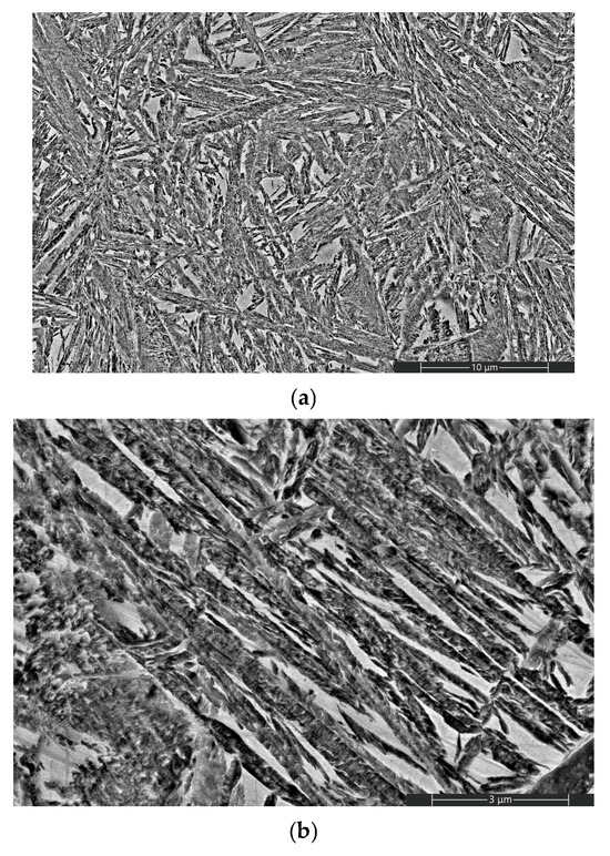
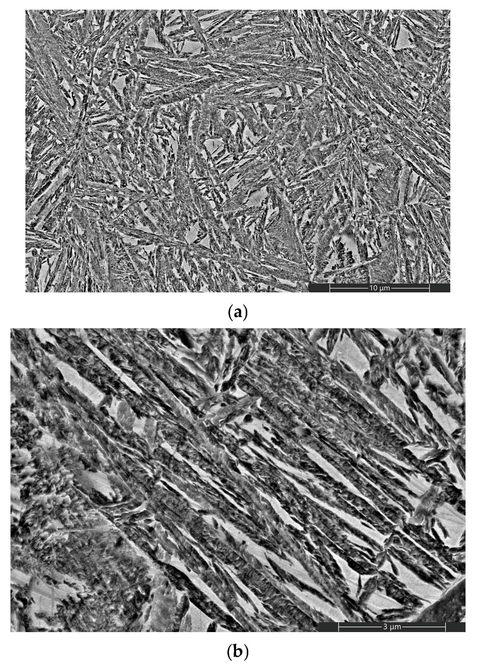
Samples of Type 1 were heat-treated according to the following route: heating in an air electric furnace in argon atmosphere to 890 °C, holding for 15 min, and transferring to a solder bath at 250 °C. Austempering time at 250 °C was 5 h. Since the austempering temperature was above the martensite start temperature (Ms) for these steels, the resulting microstructure was lower bainite. Results of dilatometry for Ms measurement and SEM pictures of bainite microstructure are shown in the Section 3.
A block cut from forged strip (for samples of Type 2) was heat-treated according to the following parameters: heating in an air electric furnace to 900 °C, holding for 30 min, air cooling for 5 min, followed by placement into the second electric furnace, preliminarily heated to 250 °C. Final holding time at 250 °C was 5 h. This heat treatment was made to obtain a bainite microstructure with only air cooling. It was possible because the critical cooling rate for this steel is lower than 0.5 °C/s (see results of dilatometry in the Section 3).
Heating samples for quenching and austempering was made using atmosphere electric furnaces Nabertherm (Nabertherm GmbH, Lilienthal, Germany) and Thermconcept KLS 03/10/M (Thermconcept GmbH, Bremen, Germany) with automatic temperature control. Type 1 samples for austempering were heated in an argon atmosphere to avoid decarburization. The temperature of the solder bath during austempering at 250 °C was maintained automatically using a thermocouple and a controller device.
The heat-treated samples were welded by the CMT method with pre-selected parameters. The idea was to limit the time of welding and, consequently, the heat input to the possible minimums using the CMT welding technique.
A single welding act was considered as the production of a single welding “dot”. After producing a “dot”, the welding joint was cooled down to normal temperature during a short pause. Therefore, the welding process consists of producing a series of dots with pauses between every subsequent “dot”. Each “dot” should be produced with the optimized quantity of short circuits. If the number of short circuits is insufficient, then heat input is also insufficient, and no quality fusion is achieved. If the number of short circuits is excessive, then heat input is also excessive, and welding defects can appear. The optimal quantity of short circuits per “dot” was 20 to 25. Detailed explanations of how welding parameters were chosen are provided in the Supplementary Materials.
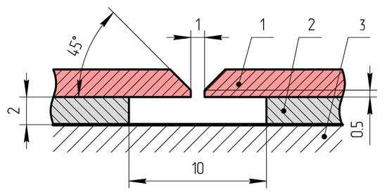
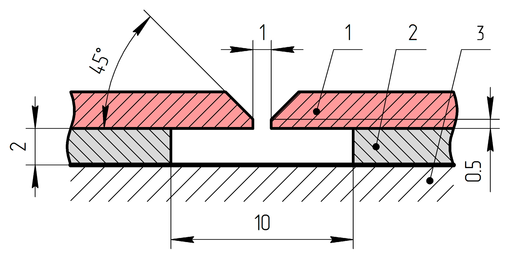
Before welding, samples were placed on a fixture as shown in Figure 1. Each sample was welded with 5 or 6 “dots”. Austenitic welding wires 308LSi (Superon Technik India Pvt. Ltd., Gurgaon, India) and RW 307Si (Rodacciai S.p.A., Bosisio Parini, Italy) (diameter 1.2 mm) were used for welding Type 1 samples. Two samples of Type 1 were welded with each type of welding wire. A sample of Type 2 was welded with 308LSi wire. After welding, the samples were ground to remove excess weld metal.
Figure 1.
Schematic view of a fixture for welding: 1—welded sample; 2—sample support; 3—workbench table.
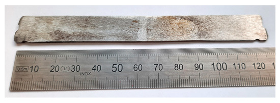
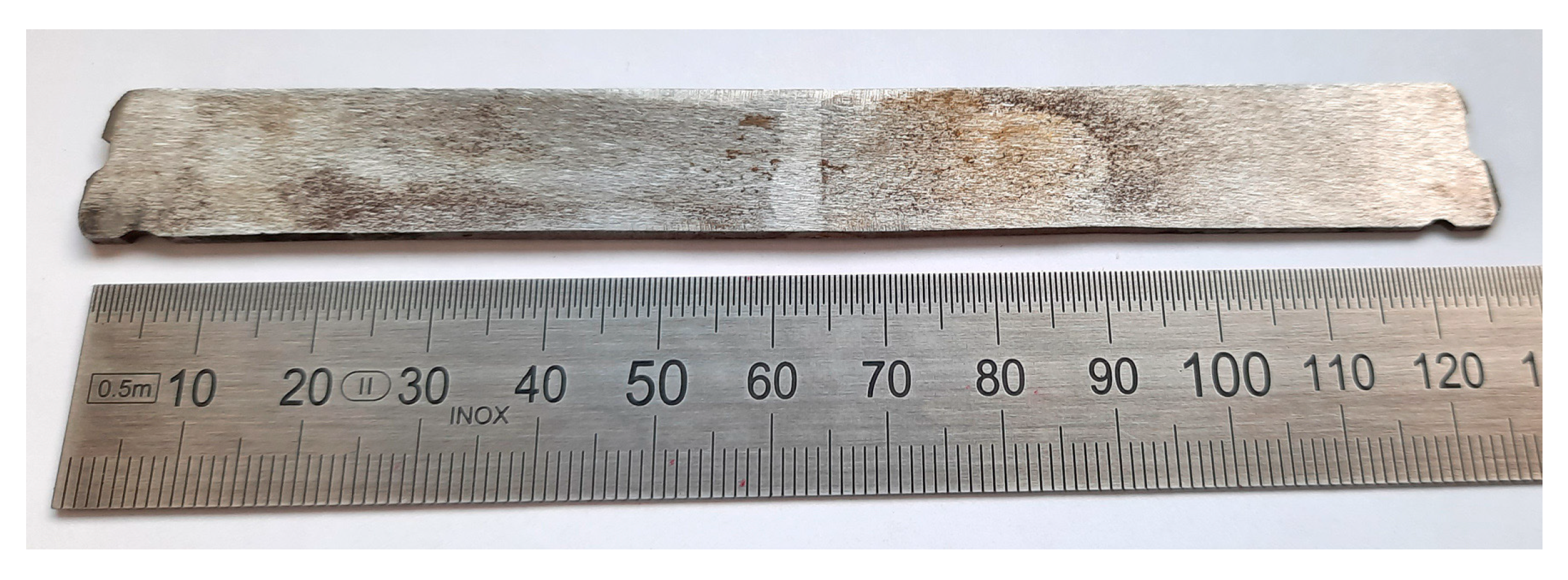
One of the welded samples of Type 1 is shown in Figure 2.
Figure 2.
Welded sample of Type 1.
Figure 3 shows the Type 1 sample after welding with RW 307Si wire and a tensile test. A piece for metallography was cut from this sample, as shown with a dashed line (1). Another small piece (2) for martensite quenching was also cut. Quenching to martensite was necessary just to compare bainite and martensite microstructures, and also to determine the hardness of untempered martensite for this steel composition. Sample (2) was martensite quenched from 890 °C (holding time 5 min, cooling in water).
Figure 3.
Type 1 sample after welding and tensile test: 1—place for cutting a piece for metallography; 2—piece for martensite quenching.
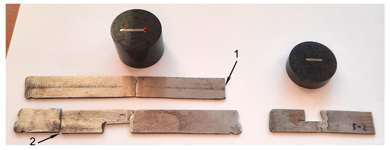
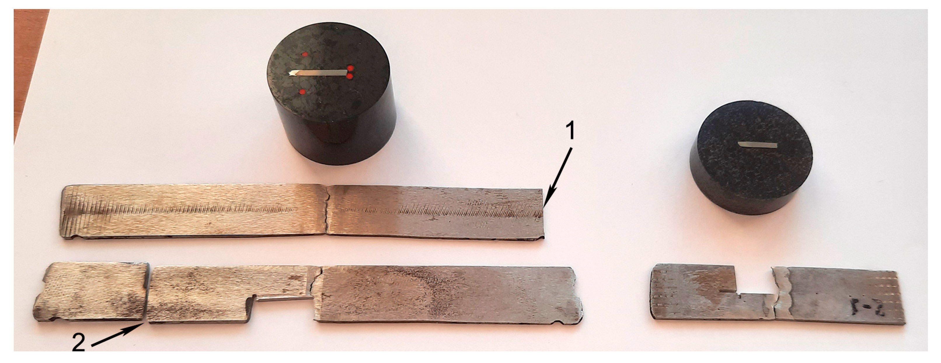
Figure 4 represents two Type 1 samples welded with RW 307 Si wire and a Type 2 sample welded with 308LSi wire. Pieces for microstructure investigations were cut from samples of Type 1 and Type 2 and prepared in due course (two black mounting resins on Figure 4). Arrow (1) indicates a place where a piece for martensite quenching was taken from. Arrow (2) indicates a cut that was made just because a piece of the Type 1 sample was too long to be fixed in the holder of the cutting machine.
Figure 4.
Samples of Type 1 and Type 2 after welding, tensile tests. Pieces for metallography and quenching are cut off.
Samples were welded using equipment of Triada Ltd. Co, Zaporizhzhia, Ukraine: a Fronius TPS500i power supply (Fronius International GmbH, Pettenbach, Austria), a Yaskawa Motoman MA14400 manipulator (Yaskawa Electric Corp., Kitakyushu, Japan), a WF 60i Robacta Drive welding wire feeder (Fronius International GmbH, Pettenbach, Austria), and a Fronius MTB 500i WR welding torch (Fronius International GmbH, Pettenbach, Austria). CO2 + Ar mix of welding gases (Ar + 2% CO2) was used as shielding gas. Compositions of welding wires are presented in the Supplementary Materials.
Tensile testing was conducted using TIRAtest 2820 (TIRA GmbH, Schalkau, Germany) and UIT STM 100 (Ukrintech Ltd., Kharkiv, Ukraine) testing machines for samples Type 1 and Type 2, respectively, under a crosshead speed of 2 mm/min. Raw results of tensile tests are presented in the Supplementary Materials.
Samples for microstructure observation were prepared using a standard grinding-polishing procedure with subsequent etching in 3% nital. Macro- and microstructure of the welding joint were investigated with optical microscope Axio Imager A2m (Carl Zeiss Microscopy Deutschland GmbH, Oberkochen, Germany) and scanning electron microscopes Apreo 2 S (Thermo Fisher Scientific Brno s.r.o., Brno, Czech Republic) and ZEISS EVO 40 (Carl Zeiss AG, Oberkochen, Germany). Hardness measurements were made with computer controlled KB30S hardness tester (KB Prüftechnik GmbH, Rhein-Pfalz-Kreis, Germany).
Dilatometry investigations were made with a Quenching Dilatometer L78 Rita (LINSEIS Messgeräte GmbH, Selb, Germany).
3. Results and Discussion
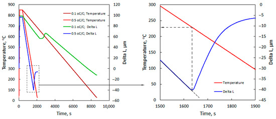
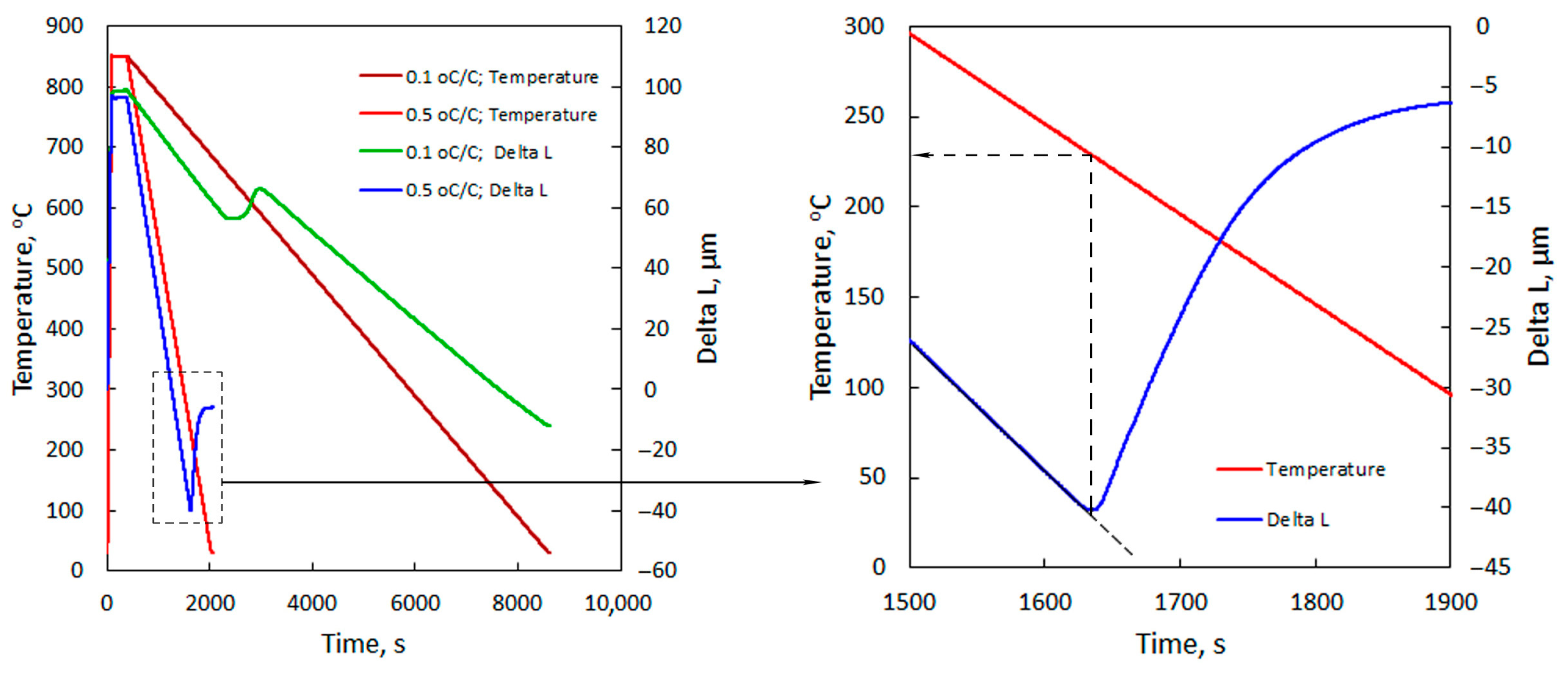
Dilatometry investigations demonstrated several significant properties of experimental steel (Figure 5). No diffusional transformation was observed at a cooling rate of 0.5 °C/s. Instead, martensite transformation took place at a temperature of about 230 °C. At a lower cooling rate (0.1 °C/s), a diffusive transformation was detected. Since Ms for experimental steel is below 250 °C, no martensite should appear during austempering at 250 °C.
Figure 5.
Results of dilatometry investigations of experimental steel.
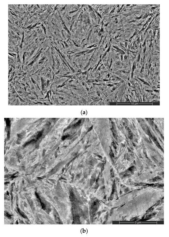
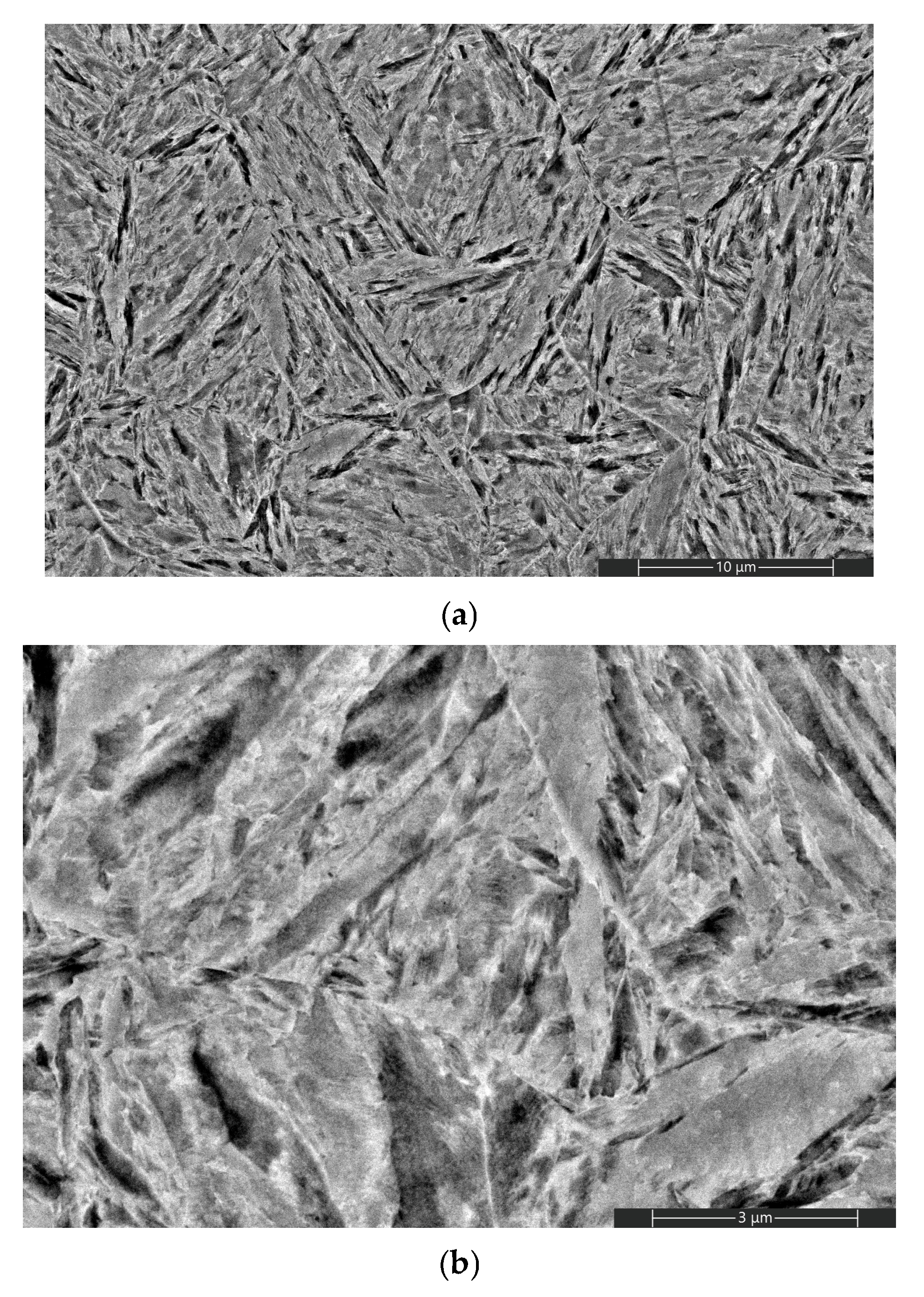
SEM micrographs of experimental steel after austempering at 250 °C for 5 h. and after quenching from 890 °C are shown in Figure 6 and Figure 7, respectively. The difference between these microstructures is obvious, especially at higher magnification. Figure 6 demonstrates a typical carbide-free bainite microstructure, which can be found in numerous references, for example, refs. [24,25]. Figure 7 shows a significantly coarser microstructure of untempered martensite. The hardness values of experimental steel after quenching and austempering also differ significantly: 720–730 HV1 after quenching and 500–520 HV1 after austempering.
Figure 6.
SEM micrographs at different magnifications of experimental steel after austempering at 250 °C over 5 h: (a) ×3000; (b) ×10,000.
Figure 7.
SEM micrographs at different magnifications of experimental steel after quenching from 890 °C: (a) ×3000; (b) ×10,000.
Table 1 and Table 2 provide welding parameters for Type 1 and Type 2 samples, respectively. Data are reported according to those recorded by the power supply. Some values of arc power do not exactly match values of current and voltage because of a very short period of welding and fluctuating current and voltage.
Table 1.
Welding parameters used for samples of Type 1.
Table 2.
Welding parameters used for sample of Type 2.
In Table 3, tensile test results are shown.
Table 3.
The results of tensile tests.
Conventional tensile strength of material for 308LSi and RW 307Si welding wires is around 620–640 MPa in as welded condition. The chemical composition of these wires is similar to that of stainless steel AISI 304, which possesses ultimate strength in the range of 500–700 MPa. RW 307Si wire also contains manganese; therefore, this material is prone to increased hardening during plastic deformation.
All samples were broken through the weld metal. Some plastic deformation occurred in all specimens before failure. Thus, quality welds in all samples were obtained.
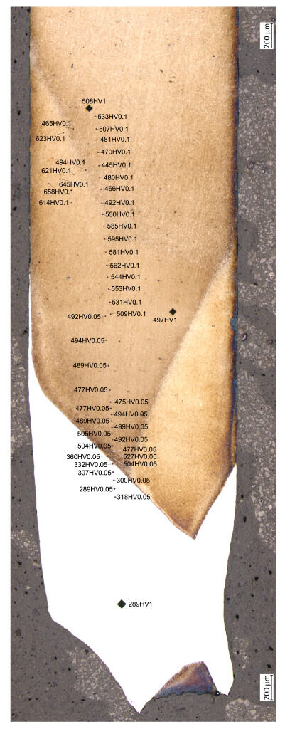
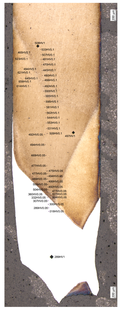
Figure 8 represents a panoramic view of the Type 1 sample welded with RW 307Si wire. Different loads were used for hardness measurements. One Newton load was used to test the base metal far from the HAZ and also the weld metal far from the fusion line. Higher load allows avoiding the influence of local microstructure fluctuations. Lower loads, i.e., 0.05 N and 0.1 N, were used for extensive microhardness measurements across HAZ.
Figure 8.
Panoramic view of Type 1 sample welded with RW 307Si wire.
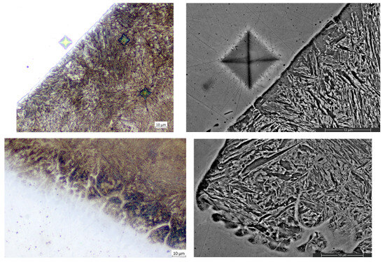
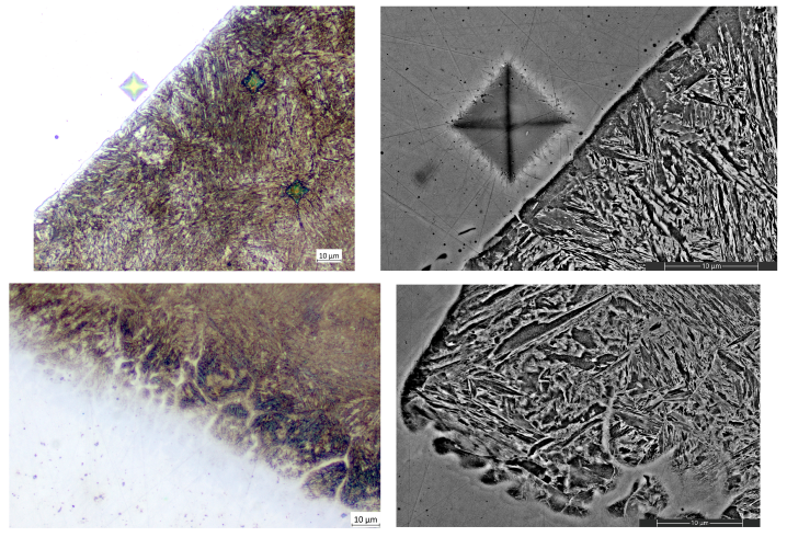
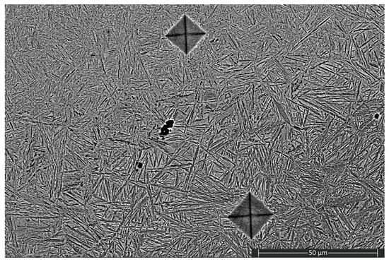
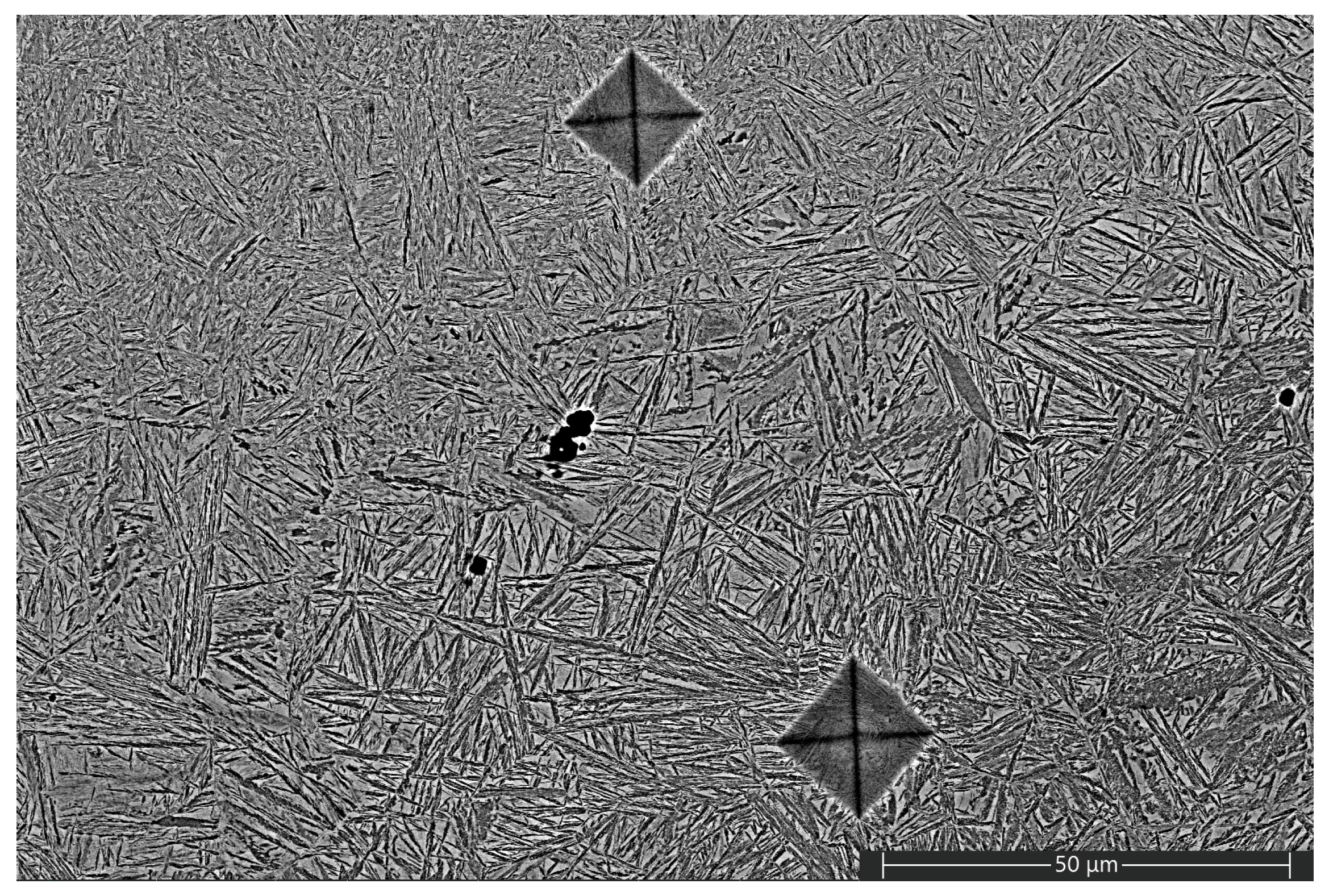
In the vicinity of the fusion line, no martensite was detected according to the hardness values obtained. Also, no cracks are visible. Optical and SEM micrographs indicate that near the fusion line, bainite-like microstructure is observed (Figure 9). Figure 10 sows SEM image of two closely located indents corresponding to microhardness values 623 HV0.1 and 425 HV0.1.
Figure 9.
Optical and SEM micrographs of fusion line of Type 1 sample welded with RW 307Si wire.
Figure 10.
SEM micrograph of indents 623 HV0.1 and 425 HV0.1.
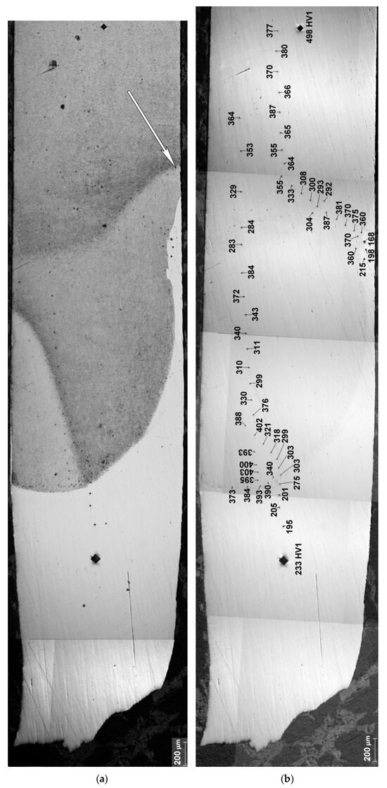
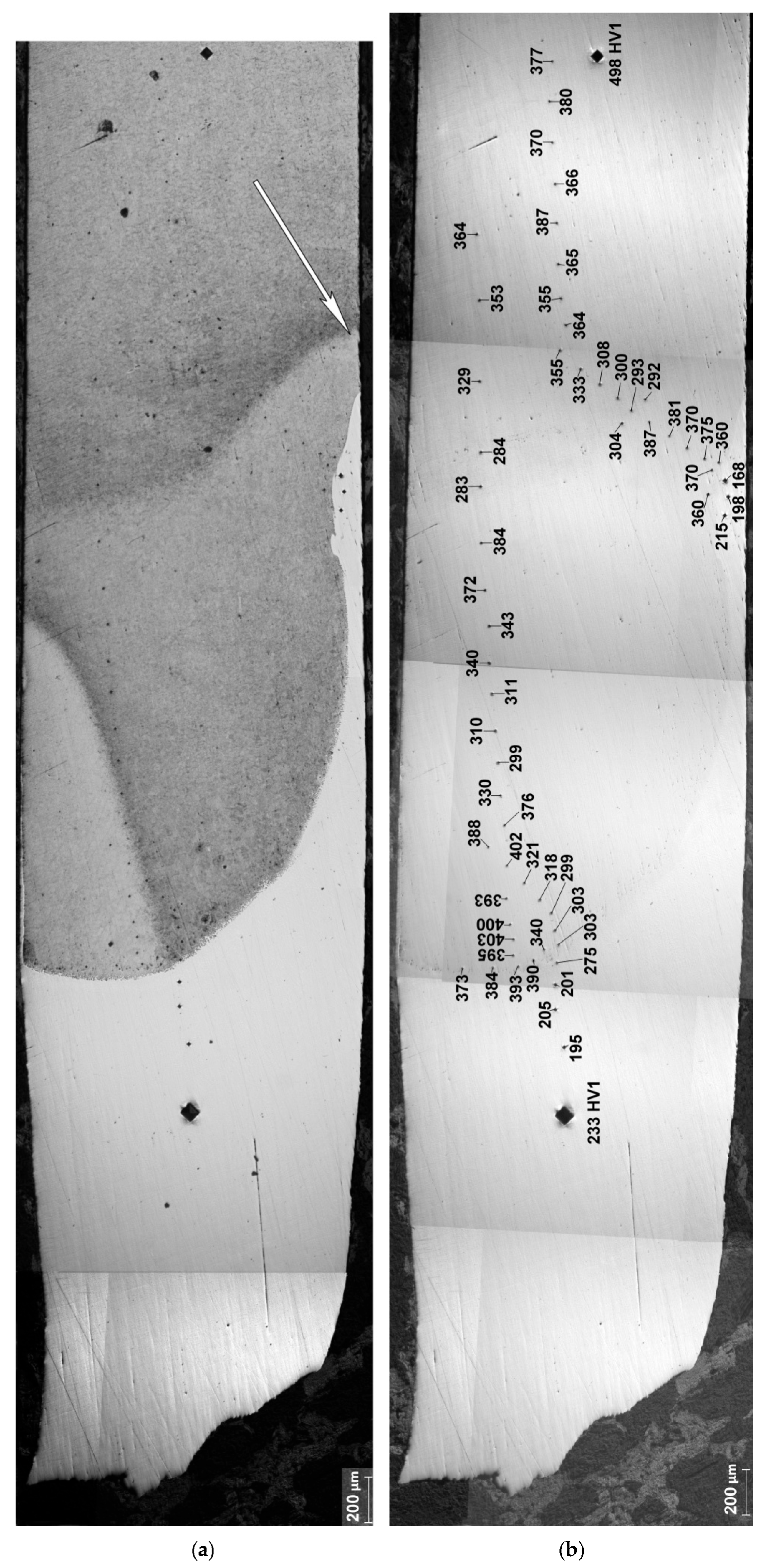
Figure 11 represents a panoramic view of the Type 2 sample welded with 308LSi wire. The general picture here is the same as for the Type 1 sample, although the hardness values in HAZ are systematically lower.
Figure 11.
Panorama of HAZ for Type 2 sample: (a) after hardness measurement and etching; (b) after hardness measurements before etching.
Macrostructure of welding joint (Figure 11a) demonstrates white non-etched austenitic filling metal and etched base metal with characteristic areas of HAZ. The distinctive zone that separates brighter areas of HAZ from darker ones is shown with an arrow.
Macrohardness measurements (Figure 11b) showed a typical hardness value for an austenitic weld metal (about 230 HV1) and base metal with the expected bainite microstructure (about 500 HV1). Extensive microhardness measurements along the HAZ and fusion line were also made (Figure 11b). As a result, it is necessary to emphasize some important observations.
Hard local zones were not revealed in HAZ. All values of microhardness are at the level of that for the base metal or less. The highest hardness in HAZ was observed in the very vicinity of the fusion line. The absence of hard zones indicates the absence of martensite; that is why cracks were not observed in HAZ.
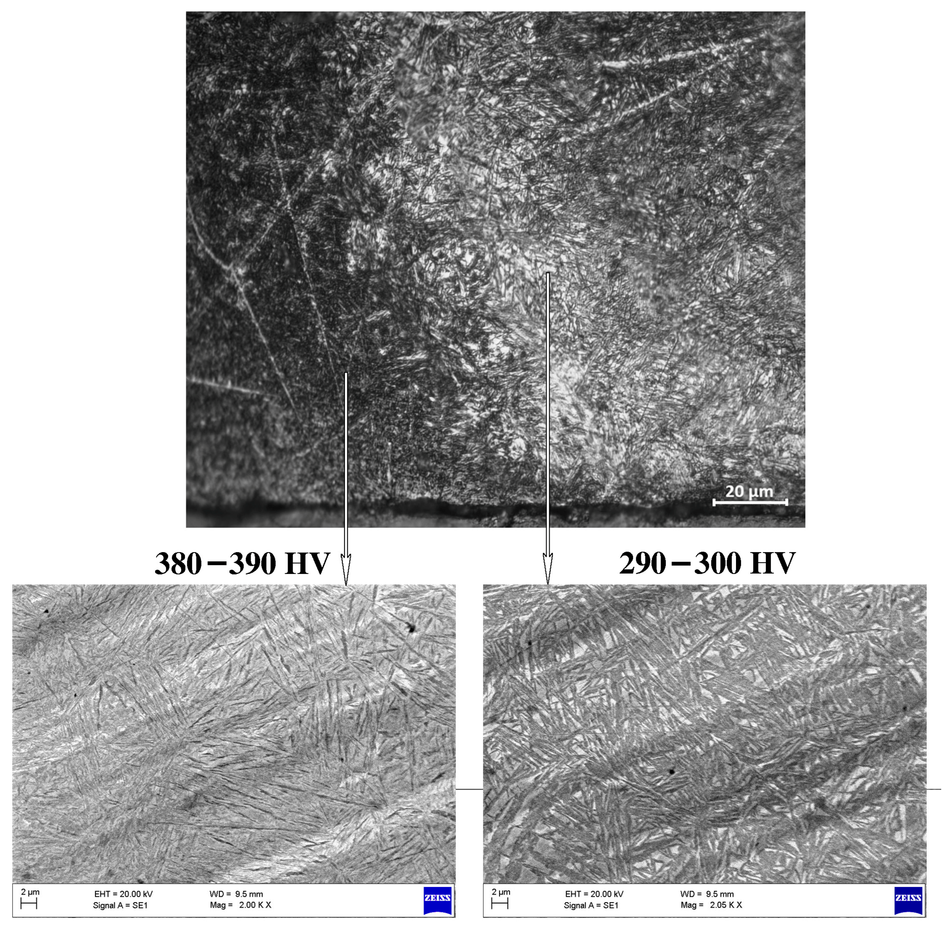
Another important observation is a local softening of the material at a certain distinctive distance from the fusion line (arrow in Figure 11a). Corresponding indents after microhardness measurements indicate a drop in microhardness from 380–390 HV0.05 to 290–300 HV0.05. Further increase in distance from the fusion line leads to a gradual increase in microhardness back to the level of base metal microhardness. This pattern of change in hardness depending on the distance from the fusion line is also observed in other areas of HAZ. Optical and SEM micrographs reveal a distinctive feature of the softening zone (Figure 12). It appears that an increased amount of austenite is present locally in HAZ on the certain distance from the fusion line.
Figure 12.
Optical and SEM micrographs of local softening zone.
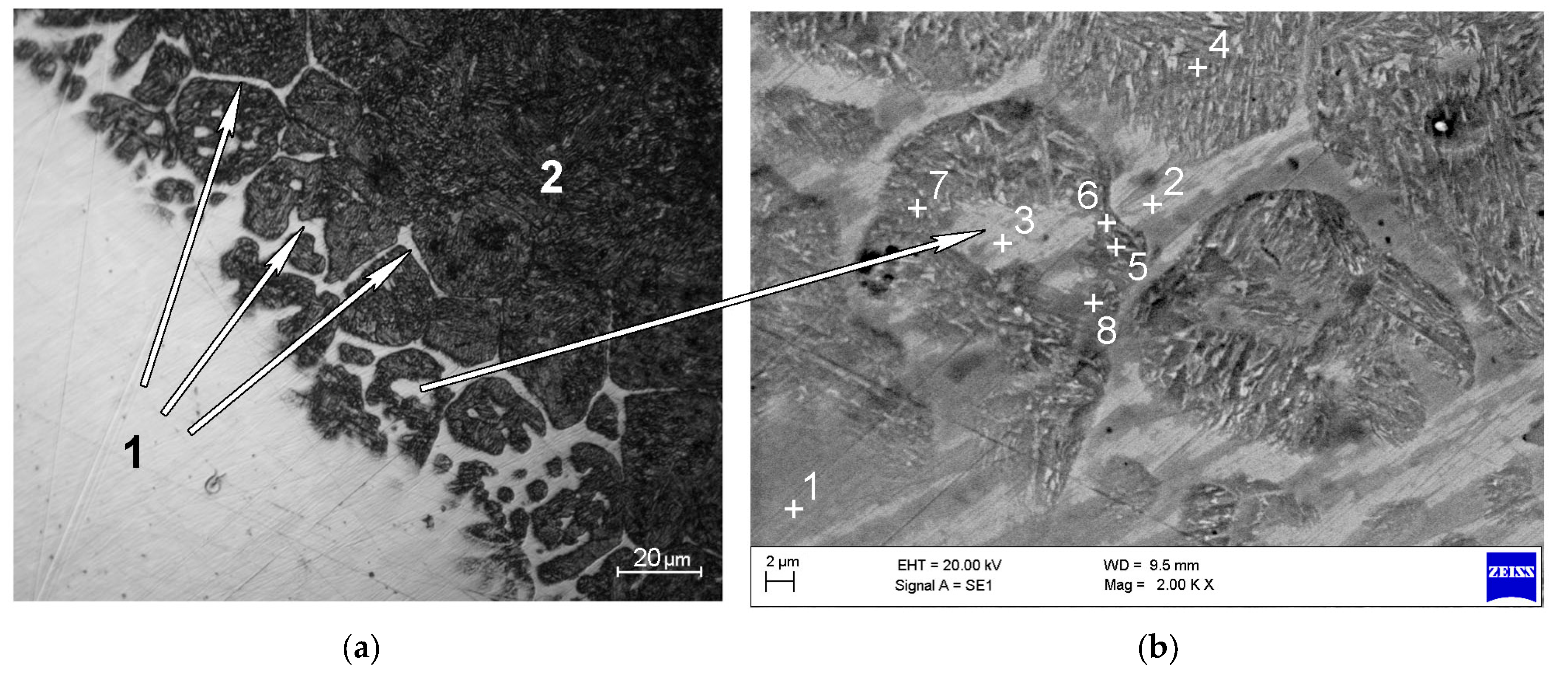
A 308LSi welding wire nominally contains Cr, Ni, Si, and Mn in quantities about (wt%) 20, 10, 1, and 1.5, respectively. Due to high Cr content, the weld metal possesses high corrosion resistance and remains unetched (white). This is clearly visible in Figure 13a (1). Also, a lot of white locations are visible along the fusion line inside the base metal at a depth of about 20–40 µm (three arrows from fusion metal on Figure 13a). Most of these white locations look like weld metal that surrounds incompletely melted grains of base metal. But some of them appear as islands inside the grains of unmelted base metal. The arrow between Figure 13a,b points to one of these locations.
Figure 13.
Local view of fusion line: (a) optical micrograph; (b) SEM micrograph with place of EDX.
There is no way for molten metal to get inside the grain of unmolten metal. The one possible explanation of appearance of “white islands” is the diffusion of alloying elements from molten grain boundaries through unmolten metal. If one supposes that the direction of diffusion is perpendicular to the grain boundary, than maximum concentration of alloying elements should be in the central zone of the partially molten grain of the base metal as a cumulative result of diffusional flows. As soon as the concentration of Cr in the central zone exceeds some threshold (about 10%), this central zone obtains high corrosion resistance and appears as an unetched “white island” inside.
Local chemical compositions around “white islands” according to EDX data are shown in Table 4. Point #3 corresponds to “white island” with enhanced content of Cr and Ni (10% and 7%, respectively) in the center of a partially melted grain of the base metal. Points #5, #6, and #7, which are very close to point #3 and surround it, contain Cr and Ni in quantities of about 1% each.
Table 4.
Local chemical composition in fusion line according to EDX data.
4. Discussion
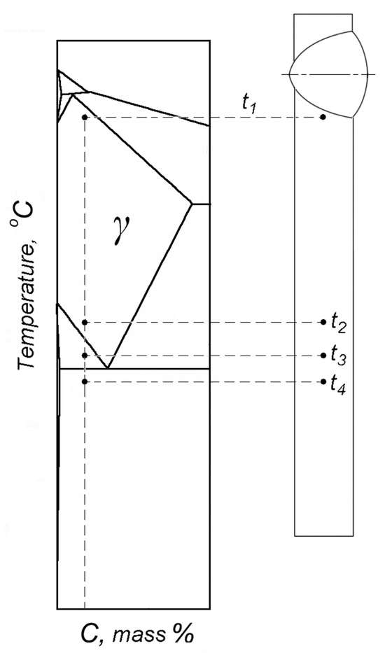
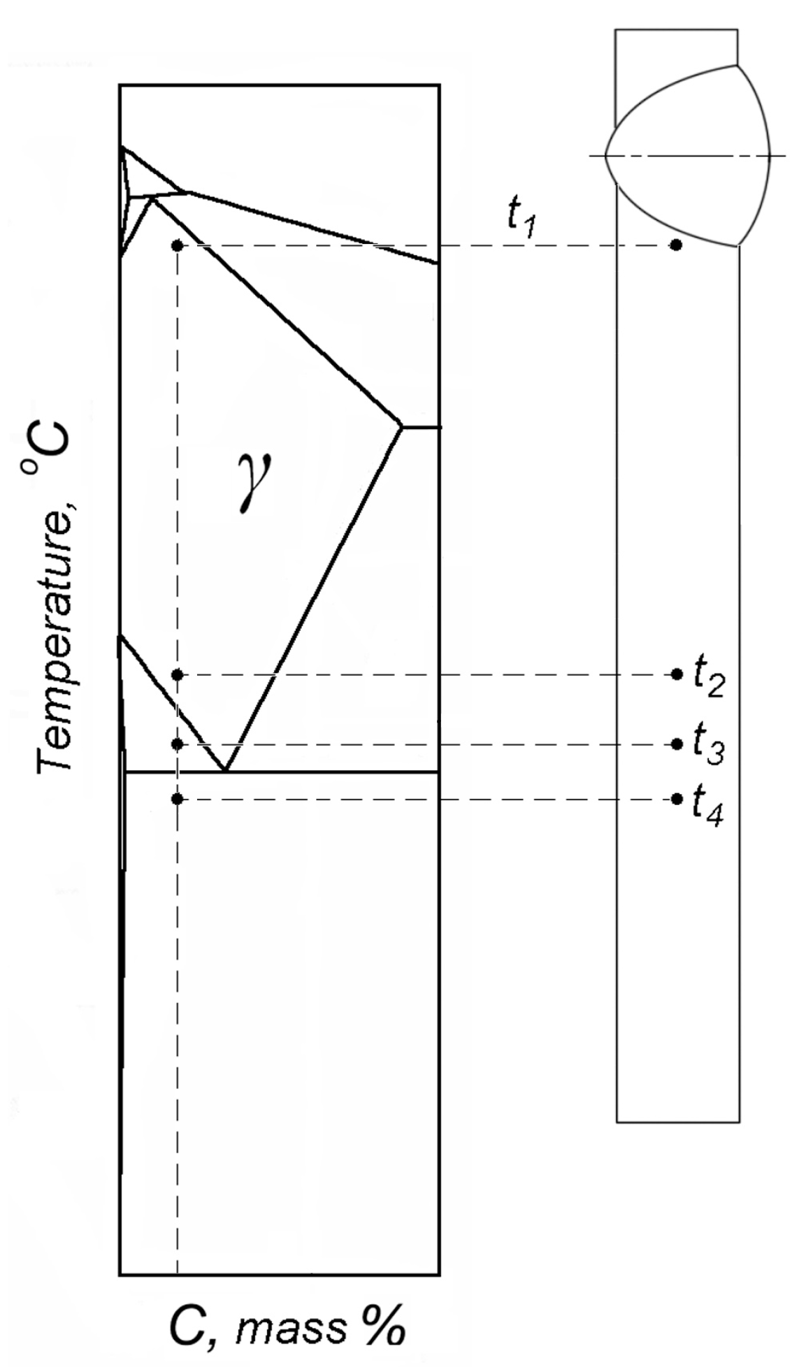
The microstructure of the different areas of the heat-affected zone is usually predicted by taking into account the phase diagram of the corresponding steel and the peak temperature of the thermal cycle developed during the welding process. For example, the phase diagram for the Fe-C-2.5 wt% Mn system can be considered for the steel composition used in the present work (Figure 14).
Figure 14.
Schematic diagram for predicting the microstructure of HAZ of experimental steel. Adapted from ref. [49].
When the material in HAZ is heated to temperatures in the range from t1 to t2, the austenite should appear. Because of the very low critical cooling rate (Figure 4), subsequent air cooling should result in martensite transformation. Therefore, high hardness of about 725 HV1 is expected in the HAZ in the vicinity of the fusion line in the distance where temperatures between t1 and t2 are developed. As this is not the case, the following circumstances can be accepted as an explanation.
The temperature field in the vicinity of a single CMT point can be represented by the equation for an impulse point heat source:
where R—distance from heat source, m; t—time, s; Q—heat input, J; c—specific heat capacity, J × kg−1 × K−1; γ—density of material, kg × m−3; and a—coefficient.
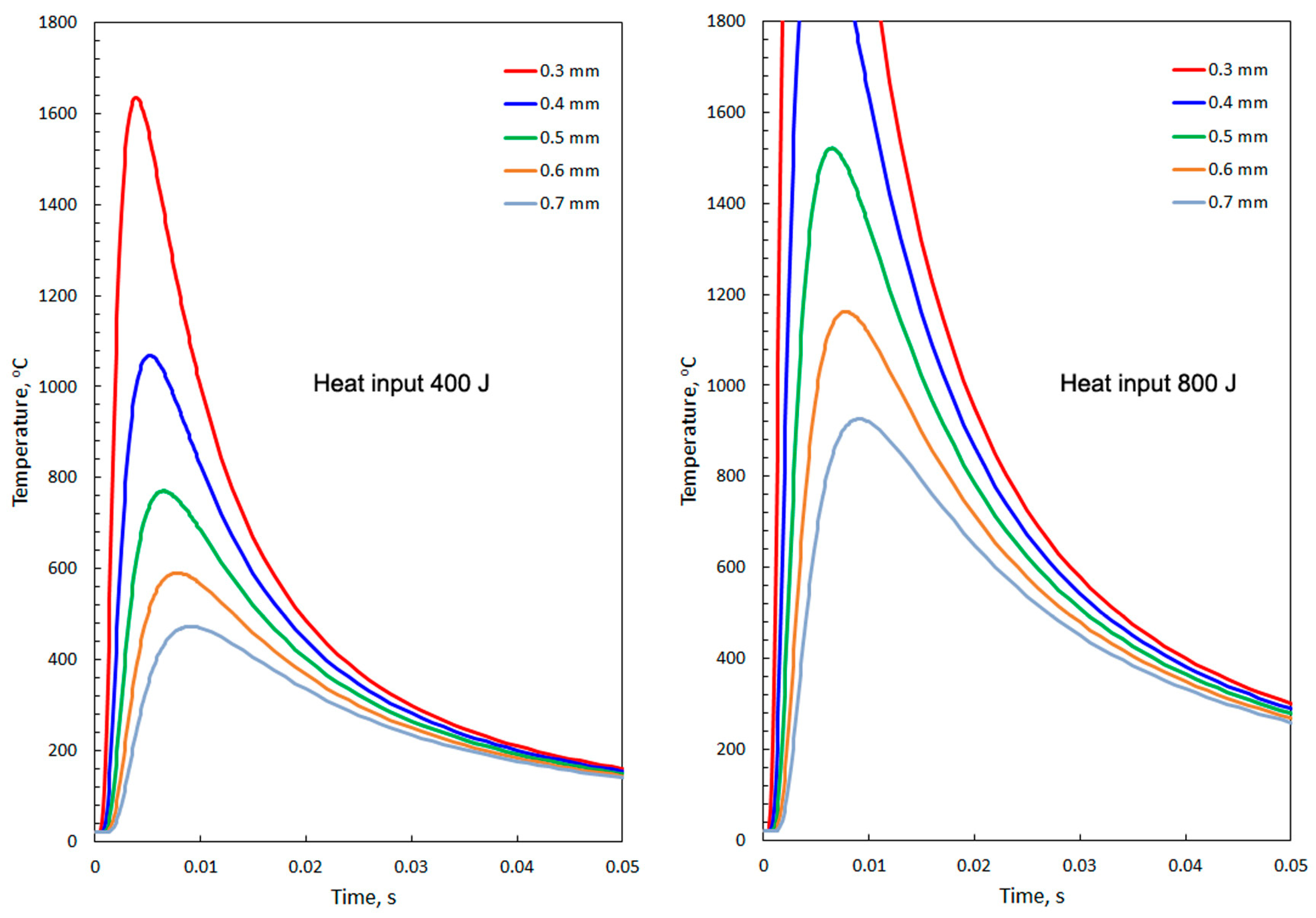
Assuming that the specific heat capacity and density of steel are 450 J × kg−1 × K−1 and 7.8 kg × m−3, respectively, the diagrams for thermal cycle were calculated for different values of heat input (Figure 15). Heat input levels are 800 J and 400 J. The first one corresponds to maximum heat input per single CMT “dot”, while the second one is 50% less, accounting for heat loss because of radiation.
Figure 15.
Calculated temperature field in HAZ after producing one CMT “dot”.
According to calculations, the material in HAZ is subjected to temperatures above Ac1 (approximately 720 °C) during a very short period of time (less than 0.05 s). For martensite to appear in the heat-affected zone, it is necessary for bainitic ferrite to transform into austenite, followed by equalization of the carbon concentration.
In ref. [50], a model is proposed for ferrite–austenite transformation in dual phase steel DP1000 during intercritical annealing. The chemical composition of steel is close to that of the steel that is investigated in this work. The main difference is much lower carbon content in DP1000 steel, i.e., 0.17 wt%. The authors assume that at the beginning of transformation, a cementite immediately transforms into austenite; therefore, austenite at the first moment is supersaturated with carbon (6.67 wt%). Hence, the ferrite (0.17 wt% C)–austenite (6.67 wt% C or less) interface is considered in the model. Different heating rates were modeled, and the minimum time to appear the first portion of austenite was 2 s.
In our case, in steel with a bainite microstructure, the laths of bainitic ferrite and austenite are in contact. Typical carbon concentrations in bainitic ferrite and austenite in lower bainite in medium carbon steel are reported elsewhere [51,52] and are 0.16 wt% and 1.20 wt%, respectively. Therefore ferrite–austenite interface in lower bainite of medium carbon steel can be correctly represented by the model [50] despite the much lower carbon content in DP1000 steel.
Comparison of temperature field calculation (Figure 15) and modeling of ferrite–austenite transformation [50] leads to the conclusion that there is no time for phase transformation in HAZ during formation of a single CMT “dot”. Time needed for ferrite–austenite transformation is at least one order of magnitude greater. These considerations can be taken as a preliminary explanation of why the hardness of HAZ is lower than that of martensite.
The results obtained in the present work indicate that it is practically possible to weld steels with high carbon equivalent using impulse techniques like CMT at very low heat input without the appearance of martensite in heat affected zone. Further research is needed to clarify the peculiarities of microstructure development in bainite steels subjected to very fast thermal cycles.
5. Conclusions
Samples of steel with high carbon equivalent (0.45 wt% C, 2.61 wt% Mn, 1.57 wt% Si) were heat-treated to carbide-free bainite microstructure and then welded with cold metal transfer technology without preheating and at very low heat input. Tensile tests of welded samples were performed. Also, the macro- and microstructure of the heat-affected zone of welded samples have been observed, along with extensive microhardness measurements. As a result of the research, the following conclusions can be drawn.
Precisely adjusted parameters of cold metal transfer welding with heat input about 500–800 J per one “dot” allow producing defect-free welding joints of medium-carbon low alloyed steel with bainite microstructure.
Tensile tests demonstrated that the fracture took place in the fusion metal only. In a heat-affected zone, neither cracks nor locations with hardness inherent to martensite were found. According to optical microscopy and SEM observations, bainite microstructure was preserved in the heat-affected zone, including locations near the fusion line.
The results obtained are discussed in terms of the time required for phase transformations in the heat-affected zone during the thermal cycle. It is shown that the time of temperature flash at low heat input is an order of magnitude shorter than the time required for the diffusive phase transformation of the material.
Supplementary Materials
The following supporting information can be downloaded at: https://www.mdpi.com/article/10.3390/constrmater6010009/s1, Video S1: Explanation CMT welding technology; Table S1. Parameters of preliminary CMT welding experiments; Table S2. Parameters of a “dot” made with 22 short circuits; Figure S1. Steel rod with a series of “dots” made with different quantity of short circuits; Figure S2. Macrostructure of a “dot” made by 22 short circuits and SEM image of fusion line; Figure S3. Samples welded with 308L Si wire; Figure S4. Samples welded with RW 307 Si wire.
Author Contributions
Conceptualization, M.B., V.L. and V.G.; formal analysis, M.B., V.L. and A.E.; methodology, M.B., O.K. (Oleksii Kapustyan) and O.K. (Olexandr Klymov); investigation, M.B., O.K. (Oleksii Kapustyan), O.K. (Olexandr Klymov), A.E. and V.G.; resources, M.B., D.M. and A.E.; data curation, M.B., A.E. and O.K. (Oleksii Kapustyan); writing—original draft preparation, M.B., V.G., O.K. (Oleksii Kapustyan), A.E. and O.K. (Olexandr Klymov); writing—review and editing, V.L., R.K. and D.M.; visualization, M.B., R.K., D.M. and A.E.; supervision, M.B. and R.K.; project administration, M.B. and D.M.; funding acquisition, M.B. All authors have read and agreed to the published version of the manuscript.
Funding
This research was funded by the National Research Foundation of Ukraine, grant number 2021.01/0189 (“New materials with a gradient nanostructure for load-bearing structures of the increased reliability and human security under special conditions”).
Data Availability Statement
All authors of this article agreed to share and republish their research data. The original contributions presented in this study are included in the article. Further inquiries can be directed to the corresponding authors.
Conflicts of Interest
The authors declare no conflicts of interest.
References
- Liu, X.; Chung, K.-F.; Ho, H.-C.; Xiao, M.; Hou, Z.-X.; Nethercot, D.A. Mechanical Behavior of High Strength S690-QT Steel Welded Sections with Various Heat Input Energy. Eng. Struct. 2018, 175, 245–256. [Google Scholar] [CrossRef] [Scilit]
- Amraei, M.; Ahola, A.; Afkhami, S.; Björk, T.; Heidarpour, A.; Zhao, X.-L. Effects of Heat Input on the Mechanical Properties of Butt-Welded High and Ultra-High Strength Steels. Eng. Struct. 2019, 198, 109460. [Google Scholar] [CrossRef] [Scilit]
- Yan, J.-B.; Luo, Y.-L.; Lin, X.; Luo, Y.-B.; Zhang, L. Effects of the Arctic Low Temperature on Mechanical Properties of Q690 and Q960 High-Strength Steels. Constr. Build. Mater. 2021, 300, 124022. [Google Scholar] [CrossRef] [Scilit]
- Yang, L.; Gao, S.; Huang, Y.; Sun, M.; Li, Y. Effect of Microstructure on Tensile and Fatigue Properties of Laser-Welded DP780 and DP980 High-Strength Steel Joints. Mater. Sci. Eng. A 2019, 754, 535–555. [Google Scholar] [CrossRef] [Scilit]
- Gao, S.; Li, N.; Huang, Y.; Yan, J.; Yang, L. Experimental Study of Fatigue Behaviour of Q690qENH Bridge Weathering High-Strength Steel Welded Joints. Thin-Walled Struct. 2023, 190, 110954. [Google Scholar] [CrossRef] [Scilit]
- Gao, S.; Yue, Y.; Zhang, D.; Li, N.; Huang, Y.; Yan, J.; Yang, L. Effect of Heat Input on the Mechanical Properties of Welded Q960E Ultra-High Strength Steel Butt Joints. Eng. Struct. 2024, 303, 117503. [Google Scholar] [CrossRef] [Scilit]
- Tümer, M.; Schneider-Bröskamp, C.; Enzinger, N. Fusion Welding of Ultra-High Strength Structural Steels—A Review. J. Manuf. Process. 2022, 82, 203–229. [Google Scholar] [CrossRef] [Scilit]
- Ullah Khan, N.; Rajput, S.K.; Gupta, V.; Verma, V.; Soota, T. To Study Mechanical Properties and Microstructures of MIG Welded High Strength Low Alloy Steel. Mater. Today Proc. 2019, 18, 2550–2555. [Google Scholar] [CrossRef] [Scilit]
- Lahtinen, T.; Vilaça, P.; Infante, V. Fatigue Behavior of MAG Welds of Thermo-Mechanically Processed 700MC Ultra High Strength Steel. Int. J. Fatigue 2019, 126, 62–71. [Google Scholar] [CrossRef] [Scilit]
- Ye, Z.; Yang, B.; Wang, W.; Yang, J.; Huang, J. High Strength Low Alloy Steel Joint Fabricated by Laser Welding with Real-Time High-Frequency Resistance Heating. J. Mater. Process. Technol. 2024, 332, 118573. [Google Scholar] [CrossRef] [Scilit]
- Lei, Z.; Cao, H.; Cui, X.; Wen, Z.; Li, L.; Zhang, Q. Study on the Suppression of Solidification Cracks in Narrow Gap Laser Welding of High-Strength Steel Based on Dual-Beam Gradient Control Weld Solidification. J. Mater. Process. Technol. 2024, 329, 118440. [Google Scholar] [CrossRef] [Scilit]
- Lei, Z.; Cao, H.; Cui, X.; Ma, Y.; Li, L.; Zhang, Q. A Novel High Efficiency Narrow-Gap Laser Welding Technology of 120 mm High-Strength Steel. Opt. Lasers Eng. 2024, 178, 108232. [Google Scholar] [CrossRef] [Scilit]
- Rajalingam, P.; Rajakumar, S.; Sonar, T.; Kavitha, S. A Comparative Study on Resistance Spot and Laser Beam Spot Welding of Ultra-High Strength Steel for Automotive Applications. Int. J. Lightweight Mater. Manuf. 2024, 7, 648–661. [Google Scholar] [CrossRef] [Scilit]
- Lemke, J.; Höfemann, M.; Biegler, M.; Rethmeier, M. Process Strategies for Optimizing the Cooling Behaviour of Laser-Welded Tailor Welded Blanks Made of Advanced High Strength Steels (AHSS). Procedia CIRP 2024, 124, 570–573. [Google Scholar] [CrossRef] [Scilit]
- Song, S.; Aminzadeh, A.; Bakhtiari, R.; Ghassemi-Armaki, H.; Butcher, C.; Biro, E. A Review of Forming Behavior and Influencing Mechanisms in Laser-Welded Advanced High-Strength Steels. Mater. Sci. Eng. A 2025, 946, 149101. [Google Scholar] [CrossRef] [Scilit]
- Manladan, S.M.; Jang, Y.; Lee, Y.-K.; Park, Y. Challenges and Advances in Resistance Spot Welding of Ultra-High Strength Hot-Stamped Steels: Coating Effect, Softening Phenomena, and Mechanical Performance. J. Mater. Res. Technol. 2024, 33, 7862–7887. [Google Scholar] [CrossRef] [Scilit]
- Yao, Z.; Omiya, M.; Ma, N.; Geng, P.; Wang, Q. Local Shear Fracture Properties in Heat-Affected Zone of Resistance Spot-Welded Advanced High-Strength Steel. J. Mater. Res. Technol. 2024, 32, 2200–2213. [Google Scholar] [CrossRef] [Scilit]
- Yang, K.; El-Sari, B.; Olfert, V.; Wang, Z.; Biegler, M.; Rethmeier, M.; Meschut, G. Expulsion Prevention in Resistance Spot Welding of Dissimilar Joints with Ultra-High Strength Steel: An Analysis of the Mechanism and Effect of Preheating Current. J. Manuf. Process. 2024, 124, 489–502. [Google Scholar] [CrossRef] [Scilit]
- Park, H.; Yoo, J.; Lee, J.-J.; Kang, Y.; Seo, K.M.; Lee, C.-H.; Ha, H.-Y.; Lee, T.-H.; Jung, S.-P.; Kim, H.-J.; et al. Impact of Hydrogen Embrittlement on the Tensile-Shear Property of Resistance Spot-Welded Advanced High-Strength Martensitic Steels. Int. J. Hydrogen Energy 2024, 71, 319–333. [Google Scholar] [CrossRef] [Scilit]
- Okigami, F.; Avedissian, N.; Ghassemi-Armaki, H.; Gao, X.; Zhang, W. Numerical Modeling of Liquid Metal Embrittlement Initiation during Resistance Spot Welding of Third Generation Advanced High Strength Steel—Effect of Welding Schedule and Electrode Alignment. J. Manuf. Process. 2024, 110, 173–191. [Google Scholar] [CrossRef] [Scilit]
- Kabirmohammadi, M.; Yazdani, S.; Ghasemi, A.; Peng, Z.; Saeid, T.; Pouranvari, M. Insights into the Microstructural Evolution and Strengthening Mechanisms of Friction Stir Spot Welded Advanced High Strength Ultrafine Bainitic Steel. Mater. Charact. 2024, 216, 114291. [Google Scholar] [CrossRef] [Scilit]
- Cui, H.B.; Hu, Y.W.; Chen, S.; Wang, C.X.; Tang, X. Control of the Microstructural Evolution and Toughness of Welded Joints by Preheating and Subsequent Cooling in Hybrid Friction Stir Welding of Q960 High Strength Steel. Mater. Today Commun. 2024, 39, 109363. [Google Scholar] [CrossRef] [Scilit]
- Caballero, F.G.; Bhadeshia, H.K.D.H.; Mawella, K.J.A.; Jones, D.G.; Brown, P. Very Strong Low Temperature Bainite. Mater. Sci. Technol. 2002, 18, 279–284. [Google Scholar] [CrossRef] [Scilit]
- Lin, S.; Borgenstam, A.; Stark, A.; Hedström, P. Effect of Si on Bainitic Transformation Kinetics in Steels Explained by Carbon Partitioning, Carbide Formation, Dislocation Densities, and Thermodynamic Conditions. Mater. Charact. 2022, 185, 111774. [Google Scholar] [CrossRef] [Scilit]
- Caballero, F.G.; Bhadeshia, H.K.D.H. Very Strong Bainite. Curr. Opin. Solid State Mater. Sci. 2004, 8, 251–257. [Google Scholar] [CrossRef] [Scilit]
- Rementeria, R.; Morales-Rivas, L.; Kuntz, M.; Garcia-Mateo, C.; Kerscher, E.; Sourmail, T.; Caballero, F.G. On the Role of Microstructure in Governing the Fatigue Behaviour of Nanostructured Bainitic Steels. Mater. Sci. Eng. A 2015, 630, 71–77. [Google Scholar] [CrossRef] [Scilit]
- Garcia-Mateo, C.; Caballero, F.G. Ultra-High-Strength Bainitic Steels. ISIJ Int. 2005, 45, 1736–1740. [Google Scholar] [CrossRef] [Scilit]
- Brykov, M.; Efremenko, V.; Gallino, I.; Petrišinets, I.; Kapustyan, O.; Klymov, O.; Efremenko, A.; Girzhon, V. Low-Alloyed Spring Steel: Nanostructure and Strength After Austempering. Metals 2025, 15, 1061. [Google Scholar] [CrossRef] [Scilit]
- Avila, D.D.S.; Van Bohemen, S.M.C.; Huizenga, R.M.; Offerman, S.E.; Santofimia, M.J. Shortening the Heat Treatment of Third Generation Advanced High Strength Steels by Forming Carbide Free Bainite in the Presence of Martensite. Mater. Sci. Eng. A 2025, 931, 148241. [Google Scholar] [CrossRef] [Scilit]
- Crouch, I.G.; Cimpoeru, S.J.; Li, H.; Shanmugam, D. Armour Steels. In The Science of Armour Materials; Elsevier: Amsterdam, The Netherlands, 2017; pp. 55–115. [Google Scholar] [CrossRef] [Scilit]
- Szymański, M. Rails with Bainitic Microstructure. Probl. Kolejnictwa-Railw. Rep. 2021, 65, 115–119. [Google Scholar] [CrossRef] [Scilit]
- Bai, L.Q.; Ding, Z.Y.; Wang, J.L.; Xie, Z.J.; Yang, Z.N.; Shang, C.J. Predicting Mechanical Properties of Bainitic Rail Steels Based on Microstructure Digitalization and Machine Learning. J. Mater. Res. Technol. 2025, 35, 2136–2143. [Google Scholar] [CrossRef] [Scilit]
- Zhang, F.C.; Yang, Z.N.; Kang, J. Research progress in bainitic steel used for railway crossing. J. Yanshan Univ. 2013, 37, 1–7. [Google Scholar]
- Sswley, K.; Sun, J. Advanced rail steels: Investigating the bainitic option. Railw. Track Struct. 1997, 3, 22–27. [Google Scholar]
- Zhang, F.C.; Wang, T.S.; Zhang, P.; Zheng, C.L.; Lv, B.; Zhang, M.; Zheng, Y.Z. Sliding wear and low cycle fatigue properties of new carbide free bainitic rail steel. Scr. Mater. 2008, 59, 294–296. [Google Scholar] [CrossRef] [Scilit]
- Huang, M.; He, B.; Li, Y.; Wang, M. TRIP-Assisted Multiphase Steel. In High Strength Steels; Elsevier: Amsterdam, The Netherlands, 2025; pp. 95–136. [Google Scholar]
- Hesse, O.; Liefeith, J.; Kunert, M.; Kapustyan, A.; Brykov, M.; Efremenko, V. Bainite in steels with high resistance against abrasive wear. Tribol. Und Schmier. 2016, 63, 5–13. [Google Scholar]
- Brykov, M.N.; Akrytova, T.O.; Osipov, M.J.; Petryshynets, I.; Puchy, V.; Efremenko, V.G.; Shimizu, K.; Kunert, M.; Hesse, O. Abrasive Wear of High-Carbon Low-Alloyed Austenite Steel: Microhardness, Microstructure and X-Ray Characteristics of Worn Surface. Materials 2021, 14, 6159. [Google Scholar] [CrossRef] [Scilit]
- Koval’, A.D.; Efremenko, V.G.; Brykov, M.N.; Andrushchenko, M.I.; Kulikovskii, R.A.; Efremenko, A.V. Principles for Developing Grinding Media with Increased Wear Resistance. Part 1. Abrasive Wear Resistance of Iron-Based Alloys. J. Frict. Wear 2012, 33, 39–46. [Google Scholar] [CrossRef] [Scilit]
- Hesse, O.; Merker, J.; Brykov, M.; Efremenko, V. On the strength of low-alloy steels with increased carbon content against abrasive wear. Tribol. Schmier. 2013, 60, 37–43. [Google Scholar]
- Zurnadzhy, V.; Efremenko, V.; Petryshynets, I.; Dabalà, M.; Franceschi, M.; Wu, K.; Kováč, F.; Chabak, Y.; Puchy, V.; Brykov, M. Alternative Approach for the Intercritical Annealing of (Cr, Mo, V)-Alloyed TRIP-Assisted Steel before Austempering. Metals 2022, 12, 1814. [Google Scholar] [CrossRef] [Scilit]
- Fang, K.; Yang, J.G.; Zhao, D.L.; Song, K.J.; Yan, Z.J.; Fang, H.Y. Review of Nanobainite Steel Welding. AMR 2012, 482–484, 2405–2408. [Google Scholar] [CrossRef] [Scilit]
- Fang, K.; Yang, J.G.; Liu, X.S.; Song, K.J.; Fang, H.Y.; Bhadeshia, H.K.D.H. Regeneration Technique for Welding Nanostructured Bainite. Mater. Des. 2013, 50, 38–43. [Google Scholar] [CrossRef] [Scilit]
- Zhang, Y.; Chen, C.; Wang, C.; Xiong, R.; Zhang, K. Effect of Shielding Gas on Keyhole Stability and Pores in Laser-CMT Hybrid Welding of Ultra-High Strength Steel. J. Manuf. Process. 2024, 132, 948–962. [Google Scholar] [CrossRef] [Scilit]
- Wang, X.; Wu, Y.; Pan, H.; Yao, C.; Huang, J. Microstructure and Softening of Advanced High-Strength Steel QP1180 Lap Joints Welded with CMT. Mater. Lett. 2021, 287, 129282. [Google Scholar] [CrossRef] [Scilit]
- Molochkov, D.; Kulykovskyi, R.; Brykov, M.; Hesse, O. The Influence of Surface Irregularities on the Mechanical Properties of Thin-Walled Wire and Arc Additively Manufactured Parts. J. Eng. Sci. 2023, 10, A10–A17. [Google Scholar] [CrossRef] [Scilit]
- Chen, M.; Zhang, D.; Wu, C. Current Waveform Effects on CMT Welding of Mild Steel. J. Mater. Process. Technol. 2017, 243, 395–404. [Google Scholar] [CrossRef] [Scilit]
- Gao, G.; Gao, B.; Gui, X.; Hu, J.; He, J.; Tan, Z.; Bai, B. Correlation between Microstructure and Yield Strength of As-Quenched and Q&P Steels with Different Carbon Content (0.06–0.42 wt% C). Mater. Sci. Eng. A 2019, 753, 1–10. [Google Scholar] [CrossRef] [Scilit]
- Rabald. Review of the book Handbuch der Sonderstahlkunde, 3rd ed., Vol. 1, by E. Houdremont (Ed.) & H.-J. Wiester (Collab.). Mater. Corros. 1957, 8, 559. [Google Scholar] [CrossRef] [Scilit]
- Ollat, M.; Militzer, M.; Massardier, V.; Fabregue, D.; Buscarlet, E.; Keovilay, F.; Perez, M. Mixed-Mode Model for Ferrite-to-Austenite Phase Transformation in Dual-Phase Steel. Comput. Mater. Sci. 2018, 149, 282–290. [Google Scholar] [CrossRef] [Scilit]
- Franceschi, M.; Morales-Rivas, L.; Cordova-Tapia, E.; Jimenez, J.A.; Dabalà, M.; Garcia-Mateo, C. Study of Bainite and Martensite Tempering in a Medium C High Si Steel. Microstructural Disparities and Equilibrium Convergence. J. Mater. Res. Technol. 2024, 32, 2931–2944. [Google Scholar] [CrossRef] [Scilit]
- Tiwari, P.; Varshney, A. Effect of Part Size on Microstructure of Medium Carbon High Silicon Steel during Austempering. Mater. Today Commun. 2025, 46, 112578. [Google Scholar] [CrossRef] [Scilit]



Disclaimer/Publisher’s Note: The statements, opinions and data contained in all publications are solely those of the individual author(s) and contributor(s) and not of MDPI and/or the editor(s). MDPI and/or the editor(s) disclaim responsibility for any injury to people or property resulting from any ideas, methods, instructions or products referred to in the content. |
© 2026 by the authors. Licensee MDPI, Basel, Switzerland. This article is an open access article distributed under the terms and conditions of the Creative Commons Attribution (CC BY) license.