Abstract
Textile-reinforced concrete (TRC) sandwich panels with lightweight cores are a promising solution for sustainable and slender building envelopes. However, their structural performance depends strongly on the shear connection between the outer shells. This study investigates the flexural behavior of TRC sandwich panels with glass fiber-reinforced polymer (GFRP) rod connectors under four-point bending. Three full-scale specimens were manufactured with high-performance concrete (HPC) face layers, an expanded polystyrene (EPS) core, and 12 mm GFRP rods as shear connectors. The panels were tested up to failure, with measurements of load–deflection behavior, crack development, and interlayer slip. Additionally, a linear-elastic finite element model was developed to complement the experimental campaign, capturing the global stiffness of the system and providing complementary insight into the internal stress distribution. The experimental results revealed stable load-bearing behavior with ductile post-cracking response. A degree of composite interaction of γ = 0.33 was obtained, indicating partially composite action. Slip measurements confirmed effective shear transfer by the GFRP connectors, while no brittle failure or connector rupture was observed. The numerical analysis confirmed the elastic response observed in the tests and highlighted the key role of the GFRP connectors in coupling the TRC shells, extending the interpretation beyond experimental results. Overall, the study demonstrates the potential of TRC sandwich panels with mechanical connectors as a safe and reliable structural solution.
1. Introduction
Sandwich panels have a broad range of applications worldwide, particularly in Europe and North America, due to their versatile structural properties and excellent insulation capabilities. These panels are typically composed of at least two outer layers and a core material, which may include various types of connectors to enhance structural integrity [1]. The structural performance of these panels depends on the type, arrangement, and properties of the connectors or core material, which define whether they behave as fully composite, partially composite, or non-composite systems [2]. However, determining this structural behavior in advance remains challenging, especially for novel designs using advanced materials like textile-reinforced concrete (TRC) and glass fiber-reinforced polymer (GFRP) connectors. This uncertainty regarding composite action highlights the need for experimental and numerical investigations to assess the actual performance and validate the assumptions used in design.
When the connectors possess sufficient stiffness, the sandwich panel functions as a bending beam, effectively distributing loads across its structure. Conversely, if the connectors are not sufficiently stiff, the outer layers, assuming they have identical stiffness, act independently, meaning the load is primarily borne by one plate [3]. Recent studies have shown that TRC can enhance the mechanical performance of sandwich panels by improving their load-bearing capacity while reducing weight [4,5,6].
The construction methodology of sandwich panels offers several advantages, including high-quality control during prefabrication, ease of installation, and excellent thermal insulation properties [7,8]. The insulation core, typically made of expanded polystyrene (EPS) or mineral wool, helps reduce thermal bridging, leading to improved energy efficiency in buildings. Previous studies on TRC sandwich panels with foam cores have already demonstrated the potential of combining lightweight insulation with thin concrete shells [9]. However, some drawbacks exist, such as limited flexibility in panel design and potential long-term durability concerns, particularly in aggressive environmental conditions [10,11,12]. To mitigate these challenges, GFRP connectors and textile reinforcements made of materials like carbon, alkali-resistant (AR) glass, or basalt are used to enhance structural integrity and durability [10]. Despite these developments, the mechanical interaction between outer TRC layers and the core—particularly the effectiveness of GFRP connectors in transferring shear forces—has not yet been fully investigated in large-scale elements.
The novel contribution of this work is threefold. First, it presents four-point bending tests on full-scale TRC sandwich panels with GFRP rod connectors and an EPS core, providing detailed measurements of load–deflection response, cracking behavior, and interlayer slip. Second, the degree of composite interaction is quantified directly from experimentally measured moment capacities and slip, rather than being inferred indirectly from stiffness-based assumptions, which are known to be sensitive to interface nonlinearity. Third, a calibrated linear-elastic finite element model is used to interpret the internal stress distribution in the TRC shells and connectors and to conduct a parametric study on layer thicknesses. Together, these results extend the existing knowledge on TRC–GFRP sandwich systems and offer guidance for the design and further optimization of such panels.
This research is part of the European Union (EU) project Iclimabuilt, which aims to reduce CO2 emissions and promote sustainable construction practices [12]. Within this framework, the present study focuses on a sandwich panel consisting of two outer layers made of TRC and an inner core of EPS insulation. GFRP connectors are used to provide mechanical interaction between the layers [13]. A detailed description of the panel geometry, reinforcement configuration, and connector layout is provided in Section 2.1.
2. Materials and Methods
2.1. Material Properties and Experimental Setup
The tested sandwich panel consists of two outer layers made of 30 mm TRC and an inner insulation core of 210 mm EPS, resulting in a total panel thickness of 270 mm. The panel dimensions are 2000 mm in length and 1000 mm in width. A single layer of carbon textile reinforcement was placed near the center of each concrete shell.
GFRP rods (Schöck Combar, 12 mm Ø) (Schöck Bauteile GmbH, Baden-Baden, Germany) were used as mechanical shear connectors. They were embedded perpendicularly (90° to the panel surface) through the entire thickness of the panel and arranged on a regular grid with 450 mm spacing along the span direction and 400 mm in the transverse direction. The first row of connectors was located 100 mm from each panel edge to ensure adequate anchorage. In addition, two connectors were placed at a 45° angle to facilitate safe lifting and handling of the panels during transport and testing. The connector layout and reinforcement configuration are illustrated in Figure 1. This construction was developed as part of the EU project Iclimabuilt to evaluate the structural performance of sustainable lightweight elements for façade and floor applications.
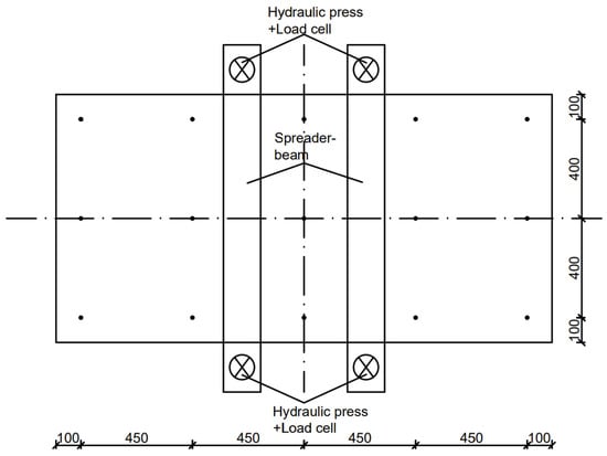
Figure 1.
Top View: Connector Layout and Hydraulic System.
Three precast sandwich panel specimens were tested under four-point bending to evaluate their structural performance. The panel geometry and material composition are summarized at the beginning of this section, while the following paragraphs describe the specific experimental configuration, including the loading setup, instrumentation, and boundary conditions. The EPS core primarily functioned as thermal insulation and was not considered a load-bearing element, whereas the two outer TRC layers were responsible for the mechanical load transfer.
The carbon textile reinforcement (product TUDALIT BZT2) (V. FRAAS Solutions in Textile GmbH, Helmbrechts, Germany) was used as a biaxial, factory-impregnated carbon grid. The main geometric and mechanical properties, including the mesh spacing in warp and weft directions, are summarized in Table 1. The polymer impregnation stabilizes the grid intersections, provides sufficient stiffness for handling, and ensures effective force transfer between the carbon filaments and the surrounding concrete.

Table 1.
Mechanical properties of textile reinforcement.
The concrete used had a compressive strength of fc,cube = 84.3 N/mm2 and a flexural tensile strength of 9.96 N/mm2, determined by testing six prisms (DIN EN 12390-5 [14]) and six cubes (DIN EN 12390-3 [15]). The concrete was classified as consistency class F4, ensuring proper flow around the textile reinforcement. A water-to-cement ratio (w/c) of 0.34 was maintained to balance workability and strength. The maximum aggregate size used in the mix was 8 mm, allowing for optimal embedding of the textile layers. The concrete mix composition used for the TRC layers is given in Table 2.
Table 2.
Concrete mix composition.
The GFRP shear connectors were tested separately on a series of ten specimens to determine their bond strength and elastic properties (DIN EN 1992-4 [16]). The main mechanical and bond properties of the GFRP connectors, obtained from manufacturer data and preliminary pull-out tests, are summarized in Table 3.
Table 3.
Main mechanical properties of the Schöck “Combar” connectors.
Pull-out strength and bond stress values were determined from six preliminary tests on GFRP connectors in accordance with DIN EN 1992-4 [16].
The specimens were fabricated as shown in Figure 2, using a sequential casting process in which each concrete layer was placed before the previously cast layer had hardened. First, a 15 mm layer of high-performance concrete (HPC) (a) was poured, followed by the placement of the carbon textile reinforcement (b), and then another 15 mm HPC layer was added (c), resulting in a 30 mm bottom shell. Immediately afterwards, the EPS insulation with pre-drilled holes was positioned on top, and the GFRP connectors were inserted through the EPS into the fresh lower HPC shell until they reached the formwork (d).
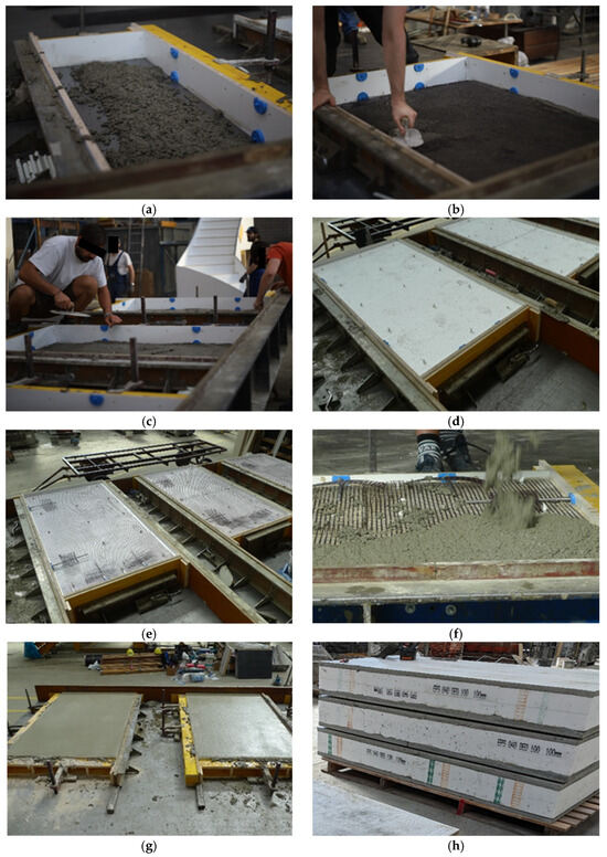
Figure 2.
Production process of the textile-reinforced concrete (TRC) sandwich panel: (a) casting the first concrete layer (15 mm); (b) placing the carbon textile reinforcement and pressing it into the fresh concrete to the target depth/position; (c) casting and troweling the second concrete layer (15 mm); (d) placing the EPS insulation layer and inserting the connector pins through the EPS; (e) placing the carbon textile reinforcement for the second layer, including additional reinforcement over the anchor zones; (f) casting the concrete for the second layer; (g) finishing the casting by troweling the top surface; (h) completed specimens.
Finally, the top shell was produced differently from the bottom shell. The carbon textile was placed directly on the EPS surface and locally attached to the GFRP rods to hold it at mid-height (15 mm) (e). In the top shell, the textile reinforcement was locally tied to the GFRP connectors, which led to slight local bulging of the mesh during casting (e,f). Due to the low density of the textile, it tended to float slightly so that fresh concrete could still flow underneath and form the required cover, and an additional textile layer was placed above the lifting anchors to ensure their secure embedding and to prevent failure of the anchors during handling and installation. Afterwards, the HPC was poured (f) and the surface was leveled using trowels (g). For the four-point bending configuration used in this study, this layer was predominantly in compression, so the small deviations in textile position were assumed to have a negligible influence on the flexural response, whereas accurate positioning of the reinforcement in the tensile zone was ensured. The panels were cured for 14 days before demolding (h), and the experiments were conducted 209 days after casting.
In both shells, the primary load transfer between the textile reinforcement and the GFRP connectors occurs indirectly through the surrounding concrete; the local ties in the upper shell were only used to control the textile position and do not represent a designed mechanical joint. Three nominally identical full-scale TRC sandwich panel specimens (SP1, SP2, and SP3) were subsequently tested under four-point bending to evaluate their structural performance.
2.2. Four-Point Bending Tests
The four-point bending tests were conducted at the Hochschule für Technik Wirtschaft und Kultur (HTWK) Leipzig (Leipzig, Germany), utilizing a setup with four servo-hydraulic presses, each capable of applying a maximum load of 400 kN. Two presses were arranged on each side to provide the loading points on the specimens, as shown in Figure 3. The support system was realized using pinned supports anchored to the foundation slab, allowing free rotation during specimen deflection. Load cells were attached to each press to accurately measure the applied forces.
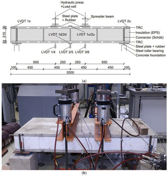
Figure 3.
Four-point bending test setup: (a) schematic view showing specimen geometry, loading and support arrangement, and linear Variable Differential Transformer (LVDT) positions; (b) photograph of the actual test setup.
The geometry of the test specimens, test setup, and the placement of LVDTs (Linear Variable Differential Transformers) (Hottinger Brüel & Kjær A/S, Darmstadt, Germany) are illustrated in Figure 3a, while Figure 3b presents a photograph of the actual test setup. The specimens were supported on concrete foundations with single and double bearings to ensure free rotation. Steel plates (300 mm wide) were used at the supports to avoid stress concentrations, and 20 mm thick hard rubber layers were added under the plates to distribute localized loads during specimen deformation.
LVDTs were used to measure vertical deflections, and relative slip between the shells. Their arrangement was as follows:
- LVDT 2 and LVDT 5: Positioned vertically under the specimens to measure the maximum deflection at the mid-span, placed approximately 40 mm from the specimen edge.
- LVDT 1, LVDT 3, LVDT 4, and LVDT 6: Positioned similarly to LVDT 2 and LVDT 5 but directly under the load application points.
- LVDT 1u and LVDT 2u: Placed on the top surface of the specimens to measure compression, with a 10 mm edge distance from the concrete edge.
- LVDT 1d and LVDT 2d: Positioned on the bottom surface of the specimens to measure tension strains, installed analogously to LVDT 1u and LVDT 2u.
- LVDT 1s and LVDT 2s: Used to measure the relative displacement between the upper and lower TRC shells (interlayer slip) near the supports. These were installed on both the left (1s) and right (2s) sides of the specimen. For each sensor, a small steel plate was rigidly fixed to the bottom TRC shell at mid-depth (15 mm from the bottom surface) directly above the support. The body of the LVDT was attached to this plate, and its measuring tip rested against a steel angle that was fixed to the upper TRC shell at the corresponding mid-depth (15 mm from the top surface). This arrangement allowed the specimen to rotate freely at the supports due to bending of the lower TRC shell, while the LVDTs recorded the horizontal slip between the two shells. The configuration is indicated schematically in Figure 3a and can also be seen in the photograph in Figure 3b.
All LVDTs were inductive displacement transducers with a nominal measurement range of 40 mm. Upon reaching the maximum measurable displacement, the LVDTs were removed to prevent damage.
The tests were carried out under displacement control, with the hydraulic system adjusted to reach 10 mm deflection within 60 s (constant deformation rate).
The loading continued until one of the following occurred:
- Significant cracking was observed in the TRC layers.
- A predefined maximum displacement was reached in the LVDTs.
- The failure of connectors or concrete layers occurred.
During testing, the displacement and strain values were continuously recorded to evaluate the load–deflection behavior and failure mechanisms.
2.3. Numerical Modeling
In addition to the experimental campaign, a linear-elastic finite element model (FEM) of the sandwich panel was developed using ANSYS Mechanical (Ansys 2024 R1) at Instituto Tecnológico de Aragón (ITA) (Zaragoza, Spain) to assess the structural response under four-point bending. The model is only focused on this linear-elastic material due to fact that the material characterization has been performed in the elastic regimen, and the modeling of the damage and multi-cracking process is out of the scope of this paper.
The geometry of the model replicated experimental specimens, including the panel dimensions (2000 mm × 1000 mm), TRC shell thickness (30 mm each), insulation core (EPS, 210 mm), and connector arrangement (GFRP rods with 12 mm diameter arranged on a 450 mm × 400 mm grid in span and transverse directions, respectively). Also, the model includes equivalent components for the supporting and loading system to match with experimental setup. This system includes two symmetric point loads and two pin supports. Figure 4 shows this model.
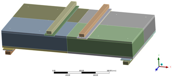
Figure 4.
Geometry of the finite element model.
The materials were modeled using linear-elastic isotropic properties: HPC for the TRC shells with E = 34,000 MPa (tested on 6 specimens; DIN EN 12390-13 [17]), and EPS with a stiffness (E = 4.5 MPa). The GFRP connectors were defined with E = 60,000 MPa and bonded ideally (perfect connection) to both TRC layers. No cracking, damage, or plasticity models were included, as the simulation aimed to reflect only the pre-cracking behavior.
To represent the interaction between shells, core, and connectors, the interfaces were idealized by tied contact conditions in the elastic range. Along the top and bottom surfaces of the EPS core, the degrees of freedom were tied to the adjacent TRC shells, enforcing full compatibility of displacements. Each GFRP connector was kinematically coupled to the TRC shells at its intersection points, representing perfect bond between connector and concrete, consistent with the assumption of “ideal bonding” mentioned above. No separate contact elements were defined between the connectors and the EPS core; due to the very low stiffness of the EPS, its contribution to axial and bending forces in the rods was assumed to be negligible. With this modeling strategy, interlayer slip and bond–slip effects were neglected, and the numerical results are restricted to the pre-cracking elastic range.
The mesh was generated primarily with linear hexahedral elements (≈99%), complemented by wedge elements where required. Mesh refinement was applied near the connectors to capture stress concentrations (Figure 5). Load steps were applied incrementally to monitor deflection and internal forces under increasing load levels. The results of the simulation are discussed in Section 3.4. The result includes the evaluation in the same position measured with LVDT.
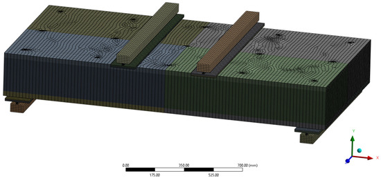
Figure 5.
Mesh of the finite element model.
3. Results
3.1. Structural Behavior
The structural performance of the sandwich panel under four-point bending was characterized by an initially linear elastic response up to approximately 8 kN, as shown in Figure 6. The three curves correspond to the three nominally identical specimens SP1, SP2, and SP3. This load level corresponds to the tensile strength of the TRC layer being exceeded, resulting in the initiation of flexural cracks in the bottom face. Based on the tangent to the initial portion of the load–deflection curve, the effective system stiffness in this range was determined to be approximately 3060 N/mm. This stiffness was determined as the slope of the initial linear portion of the global load–deflection curve (total load vs. mid-span deflection, averaged from the mid-span LVDTs).
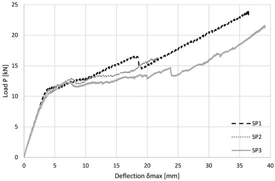
Figure 6.
Load–deflection curves of the three TRC sandwich panel specimens SP1, SP2, and SP3.
Following the first cracking event, the panel maintained its load-bearing capacity with only a moderate reduction in stiffness. This indicates that the textile reinforcement effectively bridged the cracks and contributed to load redistribution between the TRC shells. Importantly, no signs of brittle failure such as concrete spalling or sudden force drops were observed during the test. The area under the load–deflection curve, which reflects the system’s energy absorption capacity, confirms the structural contribution of both the textile reinforcement and the mechanical GFRP connectors. Even beyond the elastic limit, the applied load continued to increase steadily, demonstrating ductile behavior and stable crack propagation. This crack-bridging effect of textile reinforcement has also been reported in other TRC sandwich panel studies [18,19].
In the nonlinear region, minor slope changes appeared in the load–deflection curve. These irregularities were not caused by connector failure but were associated with the formation of additional flexural cracks and the resulting localized redistribution of internal forces in the TRC layers, particularly beneath the load introduction points and in the regions around the GFRP connectors. The corresponding crack pattern is illustrated in Figure 7.
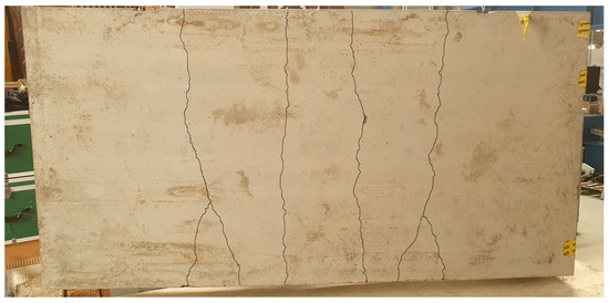
Figure 7.
Observed crack patterns after testing (bottom TRC layer and connector zones).
Based on the relative displacement between the TRC shells (S1/S2 ≈ 30 mm) and the connector embedment length of 210 mm, the deformation of the GFRP rods can be approximated as an S-shaped curvature. The estimated maximum bending angle per side (~8°) suggests that the connectors remained within their linear-elastic range during the entire test.
3.2. Moment–Normalized Deflection
To evaluate the degree of composite action, the experimental load–deflection results from Figure 6 were re-analyzed in terms of bending moment versus normalized deflection, as shown in Figure 8. Whereas Figure 6 presents the global response in terms of total load versus mid-span deflection, Figure 8 provides a derived, dimensionless representation that serves as the basis for quantifying the degree of composite interaction. The normalized deflection was defined as the ratio of the mid-span deflection to the clear span length of 1800 mm, with δ measured from the mid-span LVDTs:
where δ is the mid-span deflection and l = 1800 mm is the clear span length.
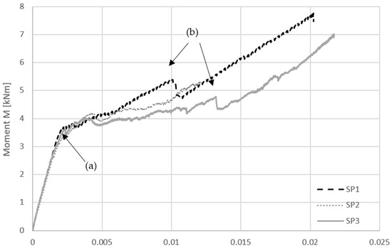
Figure 8.
Bending moment versus normalized mid-span deflection, derived from the global load–deflection response in Figure 6, with transition points between elastic and nonlinear behavior indicated.
The bending moment was calculated from the applied load and the loading configuration according to simple beam theory. Here, P denotes the total applied load from both presses, and the constant moment in the middle span is given as:
with a = 650 mm as the distance from the support to the load introduction point.
The resulting moment–normalized deflection curve shows a distinct linear range up to approximately δnorm = 0.002 m/m. Within this range, the panel exhibited purely elastic behavior. Based on this segment, the maximum transferable moment before cracking was determined as:
To assess the degree of composite interaction, this value was compared with two idealized reference cases:
- Non-composite system (Mnon):
In this simplified scenario, only one TRC shell (30 mm thick, 1000 mm wide) is assumed to carry the full bending load. Using the measured flexural tensile strength fctf = 9.96 N/mm2, the moment capacity of this single shell was estimated as:
- Fully composite system (Mfully):
In the fully composite case, both TRC shells contribute to bending with a lever arm of 240 mm (center-to-center distance between outer layers). The moment capacity was calculated using the same tensile strength and total effective force arm:
Using these values, the degree of composite action was estimated according to:
This result indicates that the panel behaves as a partially composite system. A full connection is not achieved, but the GFRP connectors enable significant interaction between the TRC layers. This classification is based on the fact that the experimental moment Mreal lies between the calculated limits for non-composite (Mnon) and fully composite (Mfully) behavior. This interpretation aligns with the observed interlayer slip behavior described in Section 3.3.
It should be noted that the value Mreal was determined based on the maximum elastic moment prior to the onset of cracking, as indicated by the linear segment of the experimental curve. Consequently, the contribution of the textile reinforcement—which only becomes active after cracking—was not included in this comparison.
Unlike some studies that compare stiffness using elastic moduli and moments of inertia (EI), for example Nguyen [20] and Lyu [21], the present evaluation relies on the measured bending moment capacities. This approach avoids the uncertainty of estimating effective EI values in nonhomogeneous sandwich cross-sections and provides a direct and experimentally grounded assessment of composite action.
Beyond the linear-elastic range, the moment–normalized deflection curve continues to rise, although at a decreasing slope ((a) in Figure 8). No abrupt drop in moment or signs of brittle failure were observed. Instead, the transition into the nonlinear range is smooth and gradual, suggesting a progressive formation of cracks in the TRC layers and an increasing contribution of the textile reinforcement to the load-bearing behavior. Small fluctuations in the moment curve were also observed, which can be attributed to the initiation and propagation of cracks ((b) in Figure 8). These observations are highlighted in Figure 8, where the transition points are marked, and they are consistent with the crack patterns shown in Figure 7.
Small changes in the slope of the curve—visible as minor inflection points—can be attributed to localized stiffness reductions caused by crack initiation and redistribution of internal forces. These effects are also evident in the corresponding crack patterns (see Section 3.1), where flexural cracks appeared predominantly in the bottom TRC shell, particularly near the GFRP connector zones.
Due to the accidental detachment of the LVDT at mid-span, the specimen SP1 could only be evaluated up to the linear-elastic range. As a result, no data beyond initial cracking could be recorded for SP1, whereas specimens SP2 and SP3 were fully monitored up to failure.
The applied method—based on directly measurable moment values—proves to be particularly suitable for systems with composite interfaces and nonlinear materials. This interpretation is further verified by the interlayer slip analysis in Section 3.3.
Comparable findings have been reported in recent studies. Cheng [22] investigated textile-reinforced mortar (TRM)-rib based sandwich panels with fiber-reinforced polymer (FRP) connectors and confirmed partially composite action through combined experimental slip measurements and FEM simulations. Similarly, Huang [19] conducted a numerical analysis on the out-of-plane shear performance of TRC sandwich panels, providing further validation that partial interaction and connector flexibility govern the overall structural response.
3.3. Interlayer Slip
To evaluate the interaction between the outer TRC layers of the sandwich panel, the relative displacement between the upper and lower shells was measured using two LVDTs (1s and 2s) placed near the supports. These sensors recorded the horizontal slip resulting from differential deformation under bending.
For each of the three nominally identical specimens (SP1–SP3), the slip shown in Figure 9 was calculated as the average of the readings from S1 and S2 and plotted against the corresponding mid-span deflection. The resulting slip–deflection curves are almost linear up to a vertical deflection of approximately 17 mm. Beyond this point, the curve remains nearly linear, with only a slight deviation from the initial slope. This behavior is illustrated in Figure 9, which shows the measured slip–deflection curves. This subtle change in curvature is likely caused by the initiation and propagation of cracks in the tensile TRC layer, which slightly alters the stiffness distribution without indicating a failure of the connectors.
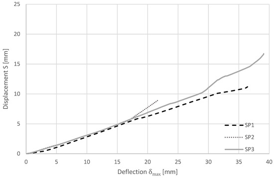
Figure 9.
Slip–deflection relationship measured from LVDTs 1s and 2s.
Throughout the loading process, the displacement progression remained smooth and continuous. This indicates that the GFRP connectors stayed structurally intact and continued to transfer shear forces between the TRC layers. While some relative movement occurred, the connectors clearly provided the necessary interaction for composite action.
This behavior aligns well with the interpretation in Section 3.2. The panel does not act as a fully rigid unit, but the presence of coordinated deformation and controlled slip confirms a partially composite system. The quantified composite action (γ = 0.33) supports this, and the interlayer slip measurements further verify the mechanical contribution of the GFRP connectors.
Based on the maximum measured relative displacement of approximately 17 mm between the outer shells (S1/S2), and an effective connector span within the core of 210 mm, the angular deformation of the GFRP rods can be estimated using simple trigonometry. Assuming an idealized S-shaped deformation, the angular deflection per side is:
This value confirms that the connectors experienced only moderate bending and remained well within their elastic range during the test. According to experimental studies on GFRP connectors in insulated sandwich panels, elastic behavior is typically maintained up to bending angles of approximately 10–15°, depending on the connector geometry [22,23]. Therefore, the measured deformation stayed safely below critical limits and did not compromise the integrity of the connectors.
Crack patterns observed (see Figure 7 in Section 3.1) after testing reinforce this conclusion: multiple cracks formed beneath the GFRP connector zones, particularly under the load application areas. These local effects likely contributed to the minor stiffness changes seen in the slip curves.
Overall, the slip behavior reflects a controlled, moderate interaction between the TRC layers. The GFRP connectors effectively transmitted shear forces, limiting interlayer displacement and enabling the panel to perform as a partially composite sandwich system, similar to observations in related studies [18,19].
3.4. Simulation Results
From the finite element model are evaluated some global and local responses. As global response, the elastic stiffness obtained from simulation is 3038 N/mm, with the measured value of 3060 N/mm. The global load–deflection behavior closely matched the initial slope observed in the test, confirming that the simplified linear-elastic material assumptions were sufficient to capture the system’s stiffness before cracking occurred.
Although no damage or cracking was modeled, the simulation provided insights into the load paths and stress redistribution within the composite system. The connectors effectively coupled the TRC shells during early loading, but the simulation confirmed that they were subjected to bending and shear deformation even within the linear regime. Figure 10 shows how the connectors are supporting compression stresses and Figure 11 shows that connectors outside of the symmetry plane supports relevant shear stresses.
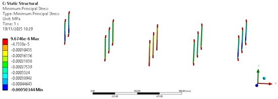
Figure 10.
Compression stress in connectors.
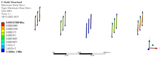
Figure 11.
Maximum shear stress in connectors.
The simulation results support the experimental interpretation that the panel does not behave as a fully composite system. Instead, the structure exhibits partial interaction between the shells. This effect is reflected in a clear linear relationship between the LVDTs (S1 and S2) and vertical deflection, such as is shown in Figure 12.
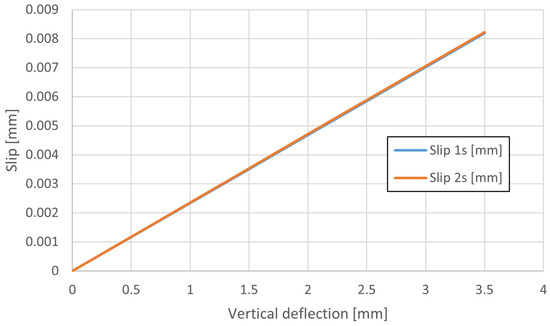
Figure 12.
Slip between the upper and bottom layer.
Stresses distribution over the panel determines that the two TRC layers behave as two independent layers in terms of stresses levels because the maximum tensile and compression stresses at each layer have similar magnitude, see Figure 13. This effect demonstrates that the TRC layers are connected but not fully coupled. It could be mitigated using a core layer with elastic modulus closer to the one of the TRC layers.
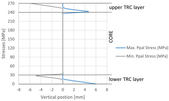
Figure 13.
Stresses in a vertical path in the center of the panel.
The numerical model provides a valuable tool for optimizing geometrical parameters—such as the number and orientation of connectors, and the thickness of layers—prior to the design phase. It enables the prediction of the elastic response of the system and the identification of critical zones that may require reinforcement in future designs. Thanks to its reduced evaluation time, the model can be used to explore a wide range of parameter combinations efficiently. Based on this capability, an optimization tool has been developed considering the following variables: number of connectors, connector angle, and layer thickness. Figure 14 presents some results of this optimization, showing the influence of layer thickness on two key outcomes: stiffness and maximum shear stresses in the connectors. The results indicate that TRC thickness has a stronger impact on both variables, while EPS thickness has a more moderate effect—its increase leads to higher stiffness but lower shear stresses in the connectors.
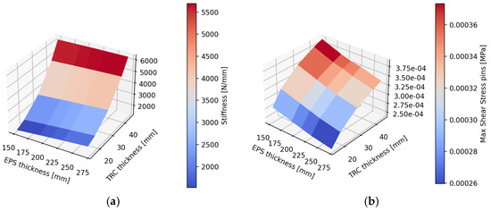
Figure 14.
Results of a parametric analysis for the thickness of the layers. (a) Stiffness and (b) Maximum shear stresses in connectors.
4. Discussion
This study combined full-scale four-point bending tests and linear-elastic finite element simulations to clarify how TRC sandwich panels with GFRP rod connectors behave in flexure. The results show that the investigated panel system develops a stable and ductile response, governed by partially composite action between the outer TRC shells.
Experimentally, the global moment–deflection behavior was linear up to a normalized mid-span deflection of about 0.002 m/m, which corresponds to first cracking of the tensile TRC shell. In this range, the measured bending stiffness agreed well with the FEM predictions, indicating that the panel geometry, material properties and connector layout were captured adequately in the numerical model. After cracking, the load–deflection curve continued to rise without sudden stiffness drops or concrete spalling. This stable post-cracking behavior confirms that the textile reinforcement effectively bridges cracks and that the GFRP connectors are capable of redistributing internal forces between the shells.
The evaluation of composite interaction, based on the experimentally obtained bending moment and the corresponding normalized deflection, yielded a degree of interaction of γ = 0.33. This value lies clearly between the fully composite and non-composite limits and therefore confirms that the panel behaves as a partially composite system. In practical terms, this means that a significant portion of the bending action is transferred between the shells through the GFRP connectors, but that assuming fully composite behavior would be unconservative. For design, it is therefore more appropriate to adopt a partially composite design approach that explicitly considers finite connector stiffness and interlayer slip.
The measured slip between the TRC shells and the observed crack patterns provides additional insight into the role of the connectors. The relative displacements remained moderate and were distributed smoothly along the span, while no connector failure or local crushing around the rods was detected. Together with the estimated S-shaped bending deformation of the connectors, this indicates that the connectors remained within their linear-elastic range for the tested load levels and that the chosen spacing and anchorage are sufficient to avoid brittle failure modes. The stress distributions obtained from the FEM along a vertical path in the center of the panel (Figure 13) show that both TRC shells develop comparable tensile and compressive stresses, confirming that both faces participate actively in bending even though full composite action is not achieved.
The parametric study on layer thicknesses further illustrates how the global panel response and the utilization of the connectors depend on the chosen geometry. Figure 14 shows that increasing the thickness of the TRC shells leads to a pronounced increase in global stiffness, but also to higher shear demands in the connectors, whereas a thicker EPS core has a more moderate effect on stiffness and tends to reduce connector shear stresses. Figure 15 summarizes the corresponding stress state in the faces by plotting the ratio between the principal stresses in the upper and lower TRC shells. The ratio of maximum principal stresses remains close to unity for all investigated configurations, which confirms that both faces are highly utilized in tension and contribute significantly to the flexural resistance. The ratio of minimum principal stresses exhibits a somewhat stronger dependence on shell thickness, particularly for the upper shell in the compression zone below the loading points. Overall, these trends emphasize that both TRC layers must be designed as active load-carrying faces and that appropriate combinations of shell and core thickness can be used to balance global stiffness, connector demand and face utilization for TRC–GFRP sandwich panels.
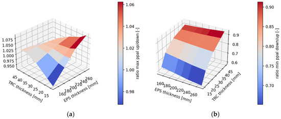
Figure 15.
Ratio between the principal stresses for both TRC layers. (a) Ratio of maximum principal stresses; (b) ratio of minimum principal stresses.
5. Conclusions
This study investigated the structural behavior of a full-scale TRC sandwich panel with an EPS insulation core and GFRP rod connectors by combining four-point bending tests with linear-elastic finite element simulations. The aim was to characterize the flexural response, quantify the degree of composite interaction between the outer TRC shells, and evaluate the stress distribution in the shells and connectors.
The experimental results showed a consistent and stable flexural behavior for the three nominally identical specimens. After first cracking of the bottom TRC shell, the load–deflection curves continued to rise without sudden force drops or concrete spalling, indicating a ductile response with stable crack propagation. The textile reinforcement effectively bridged the cracks, and no signs of connector failure were observed; interlayer slip remained moderate and compatible with a serviceable structural performance.
The evaluation of composite interaction based on bending moment versus normalized deflection demonstrated that the tested panel behaved as a partially composite system, with the experimental moment capacity lying between the non-composite and fully composite bounds. This confirms that a significant portion of the bending action is transferred between the shells via the GFRP connectors, but that assuming fully composite behavior would be unconservative. For the design of similar TRC sandwich panels, a partially composite design approach is therefore recommended, explicitly accounting for the finite stiffness of the connectors and possible interlayer slip.
The interlayer slip measurements and observed crack patterns confirmed that the GFRP connectors remained within their linear-elastic range for the loading levels considered and that slip was distributed smoothly along the span. This indicates that the chosen connector spacing and anchorage are adequate for avoiding brittle failures while still allowing deformation compatibility between the shells. The finite element model, although limited to linear-elastic behavior, reproduced the global elastic stiffness of the tested panels and provided insight into the stress distribution within the TRC shells and GFRP connectors. The parametric study on layer thicknesses showed that increasing the thickness of the TRC shells increases global stiffness but also the shear demand in the connectors, whereas a thicker insulation core reduces stiffness but decreases connector stresses. These trends offer guidance for the preliminary design and optimization of TRC sandwich panels with GFRP connectors and highlight their potential as lightweight, thermally efficient and mechanically reliable façade and floor elements. Future work should extend the numerical modeling to include non-linear material behavior and bond–slip to capture cracking and post-cracking response more accurately.
Author Contributions
Conceptualization, L.S. and B.H.-G.; methodology, L.S., M.S. and I.V., software, I.V.; validation, L.S. and I.V.; formal analysis, L.S. and I.V.; investigation, L.S., M.S., I.V. and B.H.-G.; resources, I.V. and L.S.; data curation, L.S. and I.V.; writing—original draft preparation, L.S., I.V. and B.H.-G.; writing—review and editing, L.S., M.S., I.V. and B.H.-G.; visualization, L.S. and I.V.; supervision, B.H.-G., K.H. and R.B.; project administration, B.H.-G. and R.B.; funding acquisition, B.H.-G. and R.B. All authors have read and agreed to the published version of the manuscript.
Funding
This research was conducted within the framework of the European project Iclimabuilt (H2020, Grant Agreement No. 952986). The authors gratefully acknowledge the financial support provided by the European Union’s Horizon 2020 research and innovation programme.
Data Availability Statement
The original contributions presented in this study are included in the article. Further inquiries can be directed to the corresponding author.
Conflicts of Interest
The authors declare that they have no conflicts of interest.
Abbreviations
The following abbreviations are used in this manuscript:
| ANSYS | Engineering Simulation Software used for FEM analysis |
| AR | Alkali-Resistant (typically referring to AR-glass fibers) |
| DIN | Deutsches Institut für Normung |
| EI | Flexural Rigidity (E = Elastic Modulus, I = Moment of Inertia) |
| EN | European Norm/European Standard |
| EPS | Expanded Polystyrene |
| EU | European Union |
| FEM | Finite Element Method |
| FRP | Fiber Reinforced Polymer |
| GFRP | Glass Fiber-Reinforced Polymer |
| HPC | High-performance concrete |
| HTWK | Hochschule für Technik, Wirtschaft und Kultur Leipzig |
| ITA | Instituto Tecnológico de Aragón |
| LVDT | Linear Variable Differential Transformer |
| TRC | Textile-Reinforced Concrete |
| TRM | Textile-Reinforced Mortar |
References
- Holm, A.; Künzel, H.M. Wärmedämmverbundsysteme—Planung und Ausführung; Fraunhofer IRB: Stuttgart, Germany, 2006. [Google Scholar]
- Bank, L.C. Composites for Construction: Structural Design with FRP Materials; John Wiley & Sons: Hoboken, NJ, USA, 2006. [Google Scholar]
- Carvelli, V.; Poggi, C. Mechanical behavior of sandwich panels with glass fibre reinforced polymer faces and foam core. Compos. Struct. 2001, 54, 485–492. [Google Scholar]
- Brameshuber, W.; Brockmann, T.; Wöhrle, R. Performance of textile reinforced concrete for lightweight sandwich structures. Cem. Concr. Compos. 2006, 28, 931–938. [Google Scholar]
- Venigalla, S.G.; Nabilah, A.B.; Nasir, N.A.M.; Safiee, N.A.; Aziz, F.N.A. Textile-Reinforced Concrete as a Structural Member: A Review. Buildings 2022, 12, 474. [Google Scholar] [CrossRef]
- Rambo, C.; Peled, A.; Bentur, A. Bending behavior of textile reinforced cementitious composites. Mater. Struct. 2005, 38, 651–658. [Google Scholar]
- Benayoune, A.; Samad, A.A.A.; Trikha, D.N.; Ali, A.A.A.; Ellinna, S.H. Structural behaviour of precast lightweight foam concrete sandwich panel with double shear truss connectors. Constr. Build. Mater. 2008, 22, 580–592. [Google Scholar] [CrossRef]
- Pozo-Lora, F.F.; Sorensen, T.J.; Al-Rubaye, S.; Maguire, M. State-of-the-Art and Practice Review in Concrete Sandwich Wall Panels: Materials, Design, and Construction Methods. Sustainability 2025, 17, 3704. [Google Scholar] [CrossRef]
- Smarzewski, P.; Barnat-Hunek, D. Experimental and numerical investigations on the flexural behavior of TRC sandwich panels with foam core. Constr. Build. Mater. 2021, 305, 124734. [Google Scholar]
- Chen, D.; Li, K.; Yuan, Z.; Cheng, B.; Kang, X. Shear Behavior of FRP Connectors in Precast Sandwich Insulation Wall Panels. Buildings 2022, 12, 1095. [Google Scholar] [CrossRef]
- Gil, L.; Mercedes, L.; Mendizabal, V.; Bernat-Maso, E. Shear Performance of the Interface of Sandwich Specimens with Fab-ric-Reinforced Cementitious Matrix Vegetal Fabric Skins. Appl. Sci. 2024, 14, 883. [Google Scholar] [CrossRef]
- Iclimabuilt Project. European Union Horizon 2020, Grant Agreement No. 952986. Available online: https://iclimabuilt.eu/ (accessed on 15 March 2025).
- Schöck Bauteile GmbH. Produktdatenblatt: Isokorb® Typ KXT—GFRP Connectors. 2023. Available online: https://www.schoeck.com (accessed on 15 March 2025).
- DIN EN 12390-5:2019-10; Testing Hardened Concrete—Part 5: Flexural Strength of Test Specimens; German Version EN 12390-5:2019. DIN: Berlin, Germany, 2019.
- DIN EN 12390-3:2019-10; Testing Hardened Concrete—Part 3: Compressive Strength of Test Specimens; German Version EN 12390-3:2019. DIN: Berlin, Germany, 2019.
- DIN EN 1992-4:2019-04; Eurocode 2—Design of Concrete Structures—Part 4: Design of Fastenings for Use in Concrete; German Version EN 1992-4:2018. DIN: Berlin, Germany, 2019.
- DIN EN 12390-13:2021-09; Testing Hardened Concrete—Part 13: Determination of Secant Modulus of Elasticity in Compression; German Version EN 12390-13:2021. DIN: Berlin, Germany, 2021.
- Smarzewski, P.; Barnat-Hunek, D. Analysis of shear behavior of sandwich beams with GFRP connectors and TRC faces. Compos. Struct. 2022, 287, 115306. [Google Scholar]
- Curbach, M.; Jesse, F.; Ortlepp, R.; Hegger, J. Textile reinforced concrete—From research to application. Struct. Concr. 2019, 20, 555–562. [Google Scholar]
- Nguyen, N.; Lee, J.Y.; Park, C.G. Shear behavior of GFRP connectors in insulated precast sandwich panels. Materials 2020, 13, 4803. Available online: https://www.mdpi.com/1996-1944/13/21/4803 (accessed on 15 March 2025).
- Lyu, Y.T. Evaluation of laminated composite beam theory accuracy. Adv. Struct. Eng. 2022, 25, 2501–2513. [Google Scholar] [CrossRef] [PubMed]
- Cheng, W.; Li, H.; Sun, Y.; Zhang, P. Flexural behavior of precast TRM sandwich panels with FRP composite rib connectors: Experimental and numerical investigation. Compos. Struct. 2024, 338, 117100. [Google Scholar]
- Huang, L.; Wu, Q.; Zhao, M.; Chen, Y. Numerical analysis of out-of-plane shear performance of TRC sandwich panels. Structures 2025, 60, 106487. [Google Scholar]


Disclaimer/Publisher’s Note: The statements, opinions and data contained in all publications are solely those of the individual author(s) and contributor(s) and not of MDPI and/or the editor(s). MDPI and/or the editor(s) disclaim responsibility for any injury to people or property resulting from any ideas, methods, instructions or products referred to in the content. |
© 2025 by the authors. Licensee MDPI, Basel, Switzerland. This article is an open access article distributed under the terms and conditions of the Creative Commons Attribution (CC BY) license (https://creativecommons.org/licenses/by/4.0/).