Non-Linear Numerical Modelling of Sustainable Advanced Composite Columns Made from Bamboo Culms


Abstract
:1. Introduction
1.1. Why Bamboo?
Environmental Benefits and Sustainability of Bamboo
1.2. Aim and Objectives
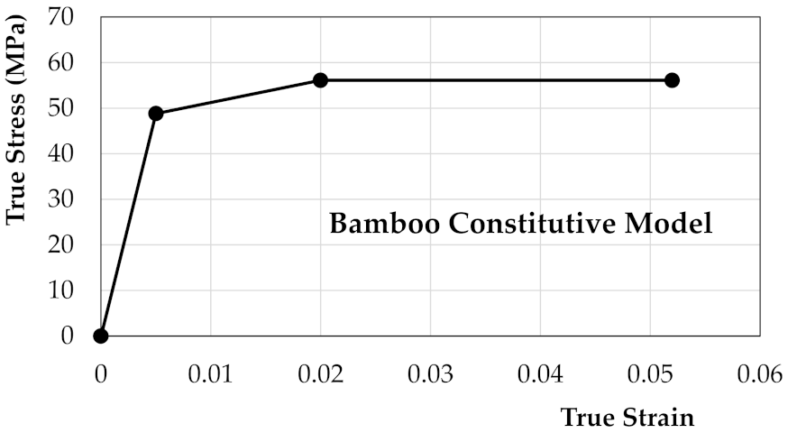
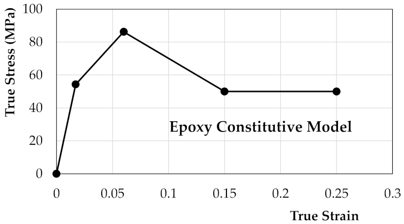
- Formulate constitutive models that describe the behaviours of the constituent parts of the composite bamboo columns, to be given as input to ABAQUS.
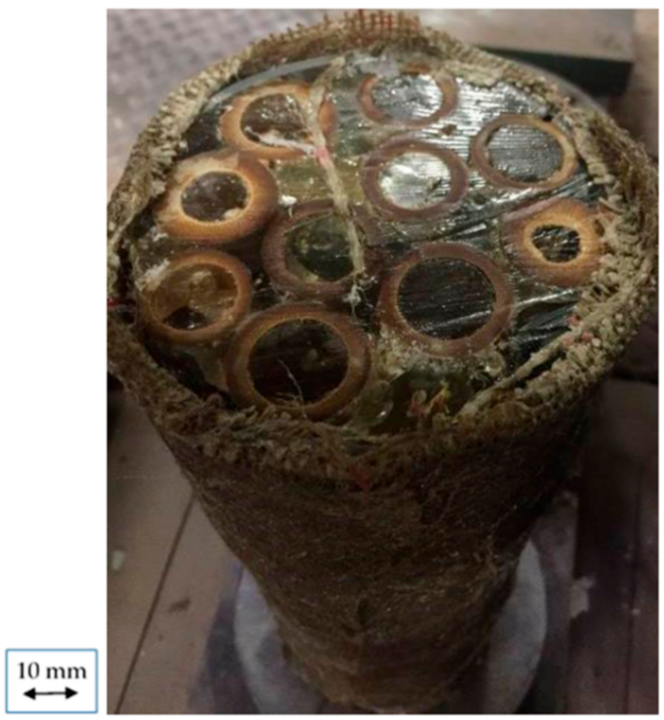
- Create numerical models that realistically represent the physical specimen produced, tested, and reported by Mofidi et al. [3].
- Use FEA to carry out a buckling analysis on the specimens under axial compressive loads considering the FEA method of analysis, Element types, and Imperfections as the parameters of the study.
- Extract the outputs from the FEA to determine the load-displacement behaviour, load at rupture, and stress distribution, and compare the results gained from the FEA with the experimental results in literature.
2. Literature Review
2.1. Research on Bamboo as a Construction Material
2.1.1. Research on Bamboo for Surface Applications
2.1.2. Research on Bamboo used as Load-Bearing Structural Members
2.2. Background to FEA of Advanced Composites
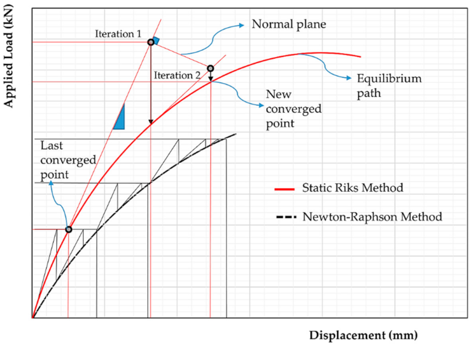
2.2.1. Static Riks Method
2.2.2. Linear Buckling/Eigenvalue Analysis
2.2.3. Imperfection Size
3. Numerical Modelling Methodology
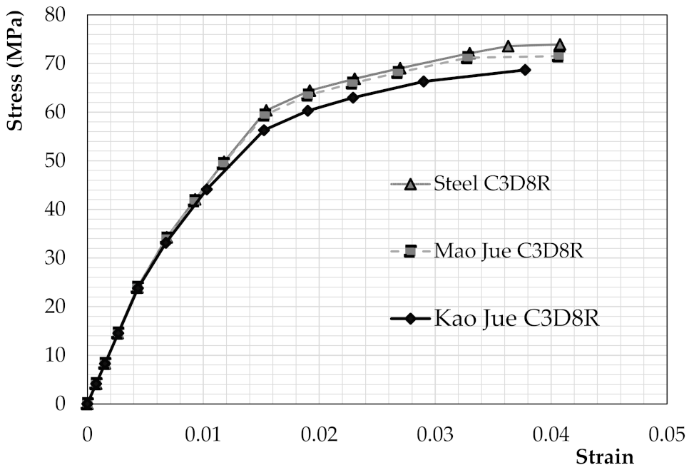
3.1. Material Properties Used as Input
3.1.1. Moso Bamboo
3.1.2. Epoxy
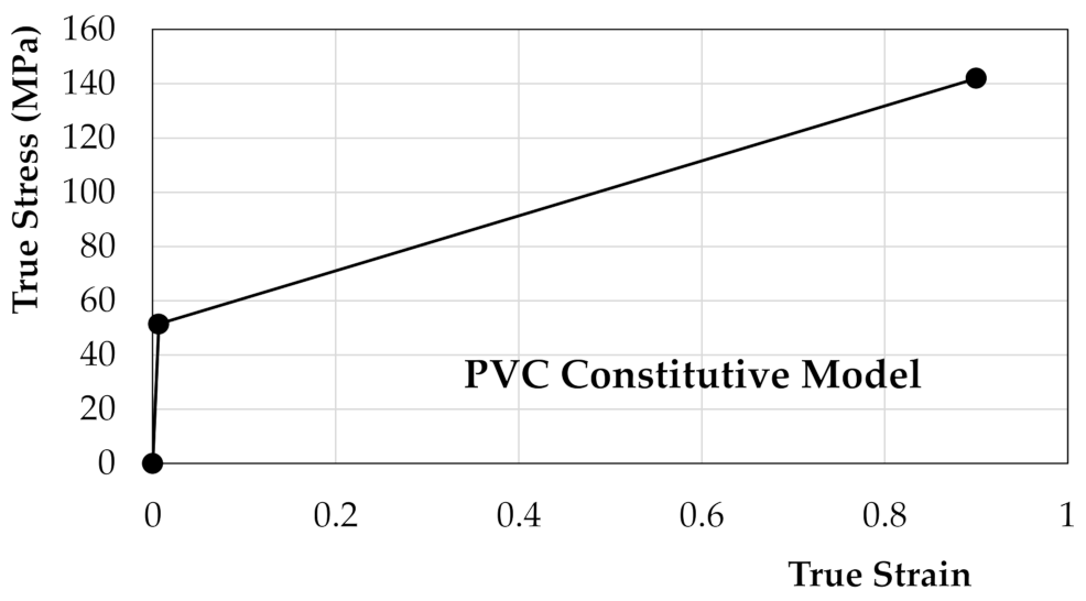
3.1.3. PVC
3.2. Eigenvalue Buckling Analysis
3.3. Contact/Interaction
3.4. Mesh Refinement and Element Types
3.5. Non-Linear Buckling Analysis Using Static Riks Method
4. Results and Discussion
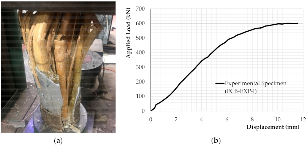
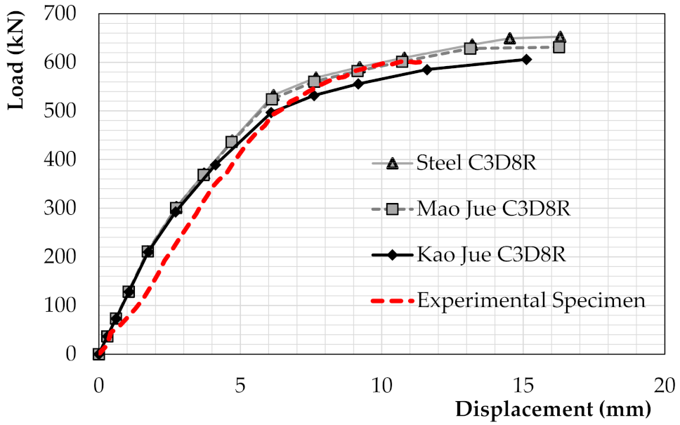
4.1. Load-Displacement Behaviour
4.2. Effect of Using Different Imperfection Sizes
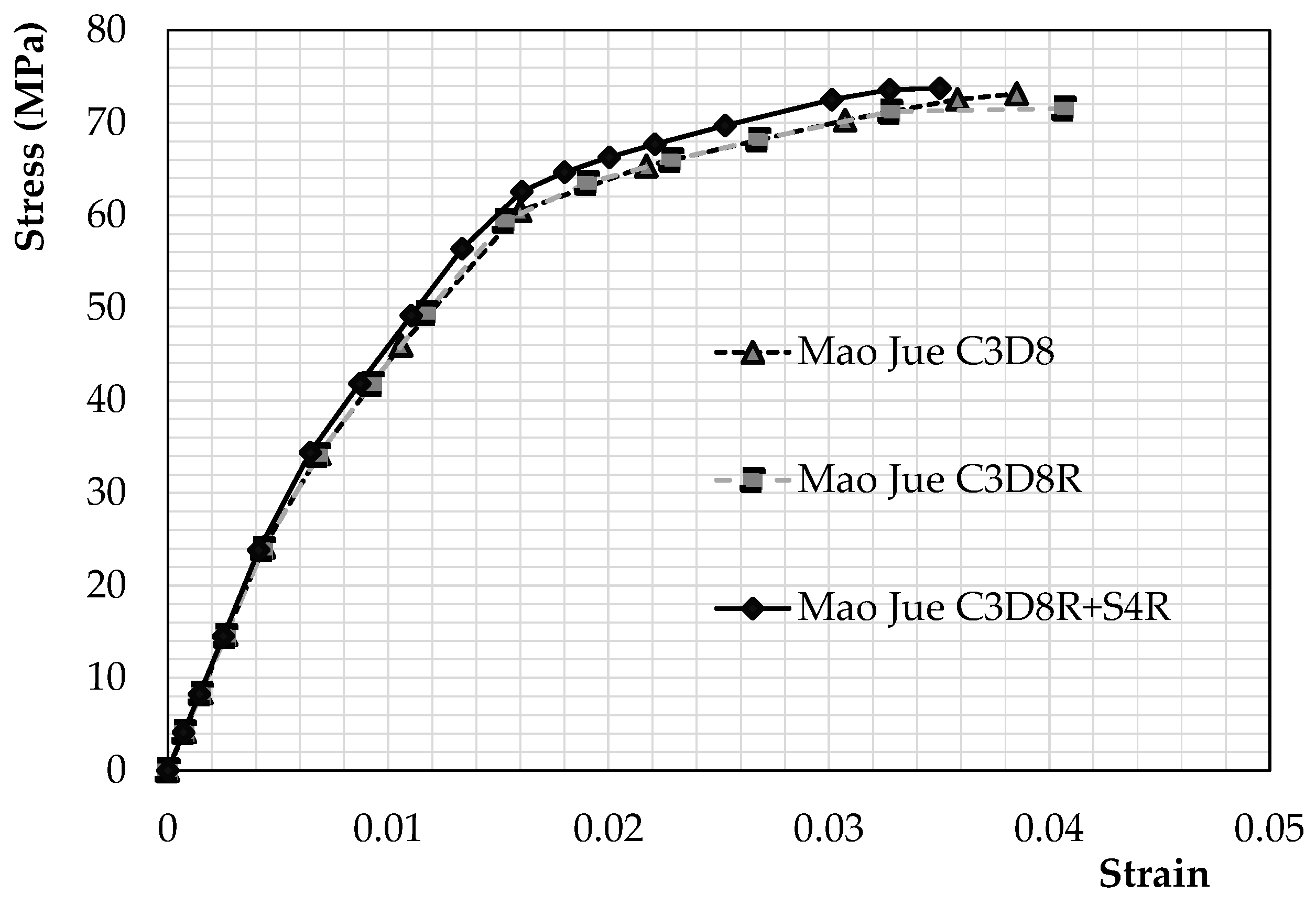
4.3. Effect of Using Different Element Types
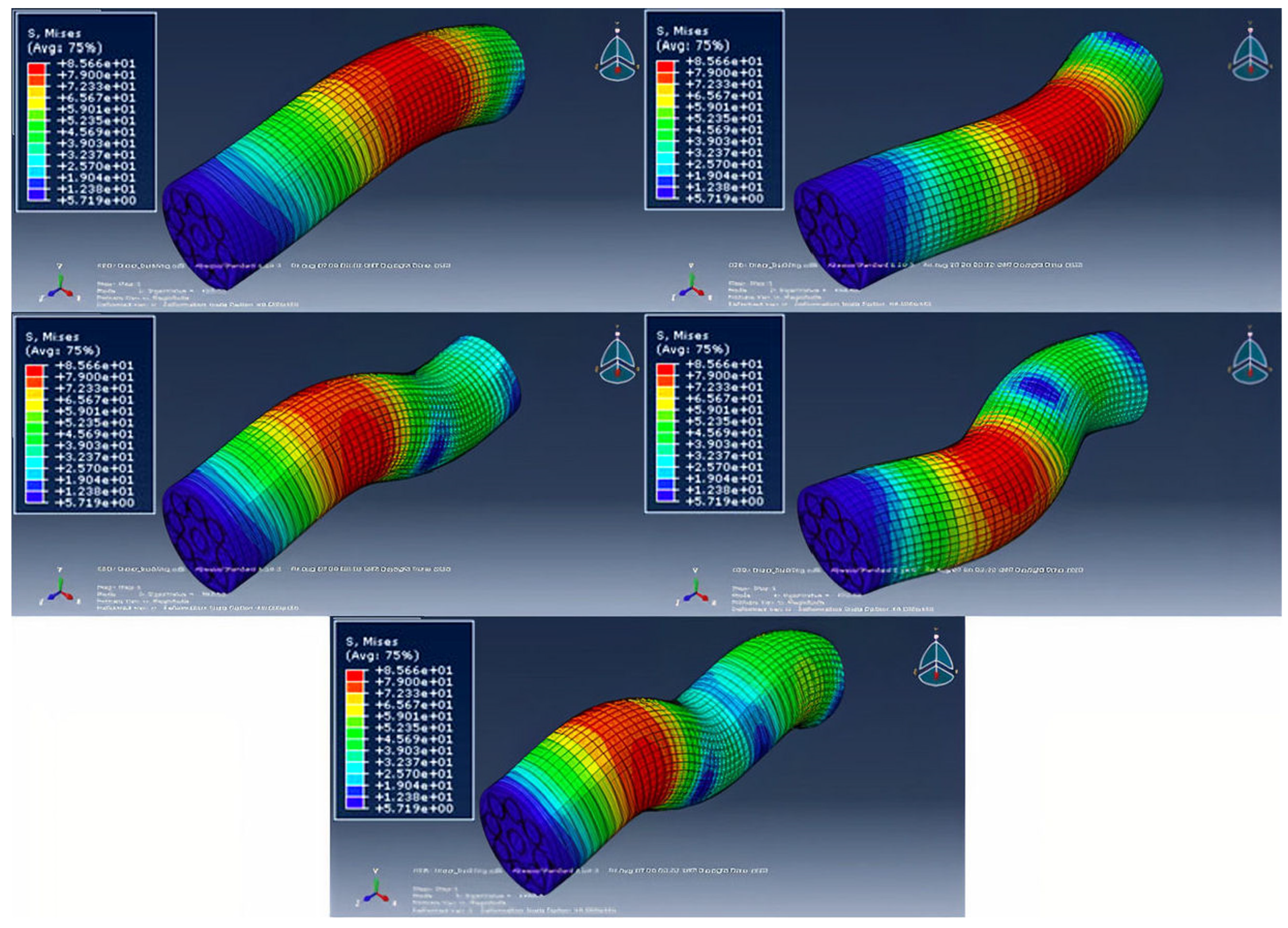
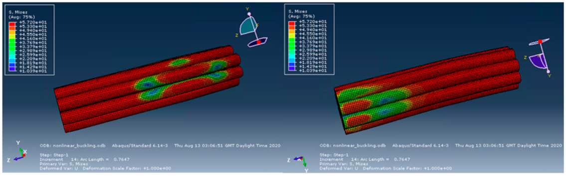
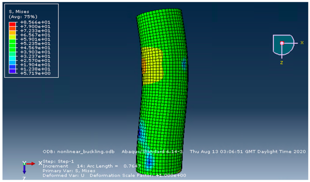
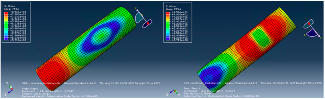
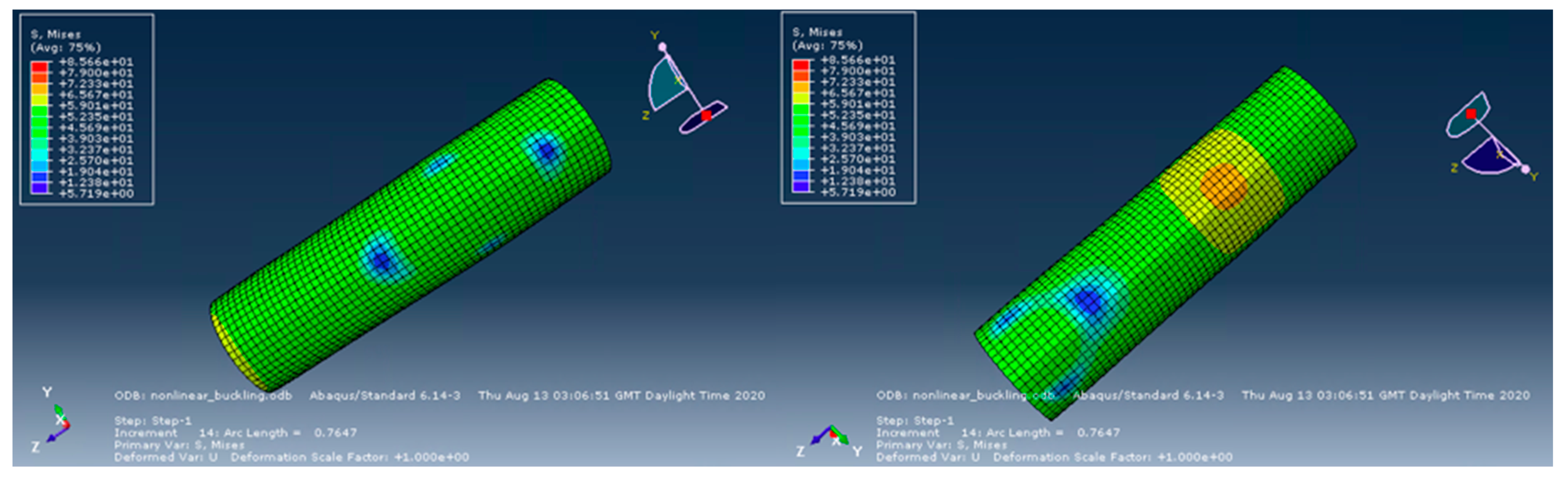
4.4. Stress Distributions
5. Conclusions
- The experimental results published by this group were supported by the FEA carried out in the present paper. The impressive load at rupture of the physical specimens (601.1kN) was either equalled or slightly exceeded by the results given by the numerical models. This confirmed the large increase in the compressive resistance of the composite member as compared to raw bamboo.
- When comparing the imperfections used for the composite bamboo models, those designed for raw bamboo work optimally as opposed to the steel imperfections based on Eurocode 3 that were also evaluated. In particular, the imperfection designed for raw Mao Jue bamboo gave results that were exceptionally close to the experimental values of load and axial deflections at rupture.
- Solid elements with reduced integration were shown to give results marginally closer to the experimental results as compared with identical elements without reduced integration.
- Shell elements were found to be sufficient when modelling the full culm Moso bamboo fibres in the model, producing outputs that were in line with the values given using solid elements. Shell elements produced the most precise prediction of axial displacement at failure.
- The stress distributions obtained by the software showed large stresses particularly in the fibres, with the matrix subject to high stress concentrations only at certain locations, and the confinement experiencing relatively moderate stresses throughout the part. This suggests that fibres that can withstand large axial compressive loads are essential to prevent failure of the composite as a whole. Bamboo performs considerably well in this role, creating advanced composites that perform exceptionally well under compressive loads, whilst being sustainable and having a low environmental impact.
Author Contributions
Funding
Data Availability Statement
Conflicts of Interest
References
- Feige, A.; Wallbaum, H.; Krank, S. Harnessing stakeholder motivation: Towards a Swiss sustainable building sector. Build. Res. Inf. 2011, 39, 504–517. [Google Scholar] [CrossRef]
- Hoffman, A.J.; Henn, R. Overcoming the social and psychological barriers to green building. Organ. Environ. 2008, 21, 390–419. [Google Scholar] [CrossRef] [Green Version]
- Mofidi, A.; Abila, J.; Ng, J.T.M. Novel Advanced Composite Bamboo Structural Members with Bio-Based and Synthetic Matrices for Sustainable Construction. Sustainability 2020, 129, 2485. [Google Scholar] [CrossRef] [Green Version]
- Nurdiah, E.A. The potential of bamboo as building material in organic shaped buildings. Procedia Soc. Behav. Sci. 2016, 216, 30–38. [Google Scholar] [CrossRef] [Green Version]
- Escamilla, E.Z.; Habert, G. Environmental impacts of bamboo-based construction materials representing global production diversity. J. Clean. Prod. 2014, 69, 117–127. [Google Scholar] [CrossRef]
- Vogtländer, J.; Van der Lugt, P.; Brezet, H. The sustainability of bamboo products for local and Western European applications. LCAs and land-use. J. Clean. Prod. 2010, 18, 1260–1269. [Google Scholar] [CrossRef]
- Asif, M. Sustainability of timber, wood and bamboo in construction. In Sustainability of Construction Materials; Woodhead Publishing: Shaxton, UK, 2009; pp. 31–54. [Google Scholar]
- Manandhar, R.; Kim, J.H.; Kim, J.T. Environmental, social and economic sustainability of bamboo and bamboo-based construction materials in buildings. J. Asian Archit. Build. Eng. 2019, 18, 49–59. [Google Scholar] [CrossRef]
- Smith, M. ABAQUS/Standard User’s Manual; Version 6.14; Dassault Systèmes Simulia Corp.: Providence, RI, USA, 2009; 862p. [Google Scholar]
- Sharma, B.; Gatóo, A.; Bock, M.; Ramage, M. Engineered bamboo for structural applications. Constr. Build. Mater. 2015, 81, 66–73. [Google Scholar] [CrossRef]
- Sharma, B.; Gatóo, A.; Ramage, M.H. Effect of processing methods on the mechanical properties of engineered bamboo. Constr. Build. Mater. 2015, 83, 95–101. [Google Scholar] [CrossRef]
- Huang, Z.; Sun, Y.; Musso, F. Assessment of bamboo application in building envelope by comparison with reference timber. Constr. Build. Mater. 2017, 156, 844–860. [Google Scholar] [CrossRef]
- Brink, F.E.; Rush, P.J. Bamboo Reinforced Concrete Construction; US Naval Civil Engineering Laboratory: Port Hueneme, CA, USA, 1966. [Google Scholar]
- Javadian, A.; Wielopolski, M.; Smith, I.F.; Hebel, D.E. Bond-behavior study of newly developed bamboo-composite reinforcement in concrete. Constr. Build. Mater. 2016, 122, 110–117. [Google Scholar] [CrossRef]
- Li, S.H.; Zeng, Q.Y.; Xiao, Y.L.; Fu, S.Y.; Zhou, B.L. Biomimicry of’ bamboo bast fiber with engineering composite materials. Mater. Sci. Eng. 1995, 3, 125–130. [Google Scholar] [CrossRef]
- Shen, L.; Yang, J.; Zhang, R.; Shao, C.; Song, X. The benefits and barriers for promoting bamboo as a green building material in China—An integrative analysis. Sustainability 2019, 11, 2493. [Google Scholar] [CrossRef] [Green Version]
- Henriques, J.; da Silva, L.S.; Valente, I.B. Numerical modeling of composite beam to reinforced concrete wall joints: Part I: Calibration of joint components. Eng. Struct. 2013, 52, 747–761. [Google Scholar] [CrossRef]
- Hrinda, G.A. Geometrically nonlinear static analysis of 3D trusses using the arc-length method. In Proceedings of the 13th International Conference on Computational Methods and Experimental Measurements, Hampton, Virginia, 2–4 July 2007; pp. 243–252. [Google Scholar]
- Zhao, M. On Nonlinear Buckling and Collapse Analysis using Riks Method. In Proceedings of the Abaqus Users’ Conference, Newport, Rhode Island, 19–22 May 2008; pp. 1–9. [Google Scholar]
- Ypma, T.J. Historical development of the Newton–Raphson method. SIAM Rev. 1995, 37, 531–551. [Google Scholar] [CrossRef] [Green Version]
- Thompson, S.P.; Loughlan, J. The active buckling control of some composite column strips using piezoceramic actuators. Compos. Struct. 1995, 32, 59–67. [Google Scholar] [CrossRef]
- Eurocode, C.E.N. 3: Design of Steel Structures-Part 1-1: General Rules and Rules for Buildings; CEN European Committee for Standardization: Brussels, Belgium, 2005. [Google Scholar]
- Yu, W.K.; Chung, K.F.; Chan, S.L. Axial buckling of bamboo columns in bamboo scaffolds. Eng. Struct. 2005, 27, 61–73. [Google Scholar] [CrossRef]
- Girão Coelho, A.; Simões da Silva, L.; Bijlaard, F. Numerical evaluation of the behaviour of the T-Stub. J. Struct. Eng. 2006, 132, 918–928. [Google Scholar] [CrossRef]
- Zhang, X.; Li, J.; Yu, Z.; Yu, Y.; Wang, H. Compressive failure mechanism and buckling analysis of the graded hierarchical bamboo structure. J. Mater. Sci. 2017, 52, 6999–7007. [Google Scholar] [CrossRef]
- Li, H.T.; Zhang, Q.S.; Huang, D.S.; Deeks, A.J. Compressive performance of laminated bamboo. Compos. Part B Eng. 2013, 54, 319–328. [Google Scholar] [CrossRef]
- Lopez, J. Optimizing the Mechanical Characteristics of Bamboo to Improve the Flexural Behavior for Biocomposite Structural Application. Master’s Thesis, California Polytechnic State University, San Luis Obispo, CA, USA, 2012; 309p. [Google Scholar]
- Fard, M.Y. Nonlinear inelastic mechanical behavior of epoxy resin polymeric materials. Ph.D. Thesis, Arizona State University, Tempe, Arizona, 2011; 192p. [Google Scholar]
- Cease, H.; Derwent, P.F.; Diehl, H.T.; Fast, J.; Finley, D. Measurement of Mechanical Properties of Three Epoxy Adhesives at Cryogenic Temperatures for CCD Construction; Fermi Lab Report Fermilab-TM-2366-A; Fermi National Accelerator Laboratory: Batavia, IL, USA, 2006; 19p. [Google Scholar]
- Yonan, S.A.; Silva, M.B.; Martins, P.A.F.; Tekkaya, A.E. Plastic flow and failure in single point incremental forming of PVC sheets. Express Polym. Lett. 2014, 8, 301–311. [Google Scholar] [CrossRef] [Green Version]
- Ognedal, A.S. Large-Deformation Behaviour of Thermoplastics at Various Stress States: An Experimental and Numerical Study. Ph.D. Dissertation, Norwegian University of Science and Technology, Trondheim, Norway, 2012; 303p. [Google Scholar]
- Kendall, M.J.; Siviour, C.R. Strain rate dependence in plasticized and un-plasticized PVC. EPJ Web Conf. 2012, 26, 02009. [Google Scholar] [CrossRef] [Green Version]
- Alves, L.M.; Martins, P.A.F. Understanding Invert Forming of Thin-Walled Polyvinyl Chloride Tubes Using a Die Based on a Mechanical Flow Formulation. Mater. Manuf. Process. 2009, 24, 1398–1404. [Google Scholar] [CrossRef]
- Ranganathan, S.I.; Abed, F.H.; Aldadah, M.G. Buckling of slender columns with functionally graded microstructures. Mech. Adv. Mater. Struct. 2016, 23, 1360–1367. [Google Scholar] [CrossRef]
- Poiate, I.A.; Vasconcellos, A.B.; Mori, M.; Poiate, E., Jr. 2D and 3D finite element analysis of central incisor generated by computerized tomography. Comput. Methods Programs Biomed. 2011, 104, 292–299. [Google Scholar] [CrossRef] [PubMed]
- Sadowski, A.J.; Rotter, J.M. Solid or shell finite elements to model thick cylindrical tubes and shells under global bending. Int. J. Mech. Sci. 2013, 74, 143–153. [Google Scholar] [CrossRef] [Green Version]
- Aten, Q.T.; Jensen, B.D.; Howell, L.L. Geometrically non-linear analysis of thin-film compliant MEMS via shell and solid elements. Finite Elem. Anal. Des. 2012, 49, 70–77. [Google Scholar] [CrossRef]
- Zhuang, Z.; Liu, Z.; Cheng, B.; Liao, J. Extended Finite Element Method; Tsinghua University: Beijing, China, 2014; 271p. [Google Scholar]


| Specimen | Load at Rupture (kN) | Area of Cross-Section (mm2) | End Shortening at Peak (mm) | Density of Specimen (kg/m3) | Axial Stress (MPa) | Gain (%) | Capacity Over Weight (kN/kN) |
|---|---|---|---|---|---|---|---|
| Control | 152.4 | 2764.6 | 5.75 | 1147.3 | 55.1 | − | 12,323 |
| FCB-EPX-I | 601.1 | 8332.3 | 13.82 | 1174.5 | 72.1 | 294.4 | 15,681 |
| Element Used | Imperfection (mm) | Load at Rupture (kN) | Axial Displacement at Rupture (mm) | Axial Stress at Rupture (MPa) |
|---|---|---|---|---|
| C3D8R | 2.67 | 652.4 | 16.31 | 73.93 |
| C3D8R | 3.40 | 631.2 | 16.26 | 71.52 |
| C3D8R | 6.40 | 606.0 | 15.11 | 68.67 |
| C3D8 | 2.67 | 655.3 | 15.49 | 73.55 |
| C3D8 | 3.40 | 645.4 | 15.41 | 73.13 |
| C3D8 | 6.40 | 607.2 | 15.26 | 68.80 |
| C3D8R + S4R | 3.40 | 650.8 | 14.01 | 73.74 |
Publisher’s Note: MDPI stays neutral with regard to jurisdictional claims in published maps and institutional affiliations. |
© 2021 by the authors. Licensee MDPI, Basel, Switzerland. This article is an open access article distributed under the terms and conditions of the Creative Commons Attribution (CC BY) license (https://creativecommons.org/licenses/by/4.0/).
Share and Cite
Richardson, C.; Mofidi, A. Non-Linear Numerical Modelling of Sustainable Advanced Composite Columns Made from Bamboo Culms. Constr. Mater. 2021, 1, 169-187. https://doi.org/10.3390/constrmater1030011
Richardson C, Mofidi A. Non-Linear Numerical Modelling of Sustainable Advanced Composite Columns Made from Bamboo Culms. Construction Materials. 2021; 1(3):169-187. https://doi.org/10.3390/constrmater1030011
Chicago/Turabian StyleRichardson, Cameron, and Amir Mofidi. 2021. "Non-Linear Numerical Modelling of Sustainable Advanced Composite Columns Made from Bamboo Culms" Construction Materials 1, no. 3: 169-187. https://doi.org/10.3390/constrmater1030011
APA StyleRichardson, C., & Mofidi, A. (2021). Non-Linear Numerical Modelling of Sustainable Advanced Composite Columns Made from Bamboo Culms. Construction Materials, 1(3), 169-187. https://doi.org/10.3390/constrmater1030011