
Article

Undrained Bearing Capacity of Strip Foundation Under Inclined Loading Lying on Two-Layered Slopes

1
InfraRES Laboratory, Mohammed Cherif Messaadia University, Souk-Ahras 41000, Algeria
2
3SR Laboratory, CNRS, Grenoble INP, University Grenoble Alpes, F-38000 Grenoble, France
*
Author to whom correspondence should be addressed.
Geotechnics 2026, 6(2), 42; https://doi.org/10.3390/geotechnics6020042

Submission received: 3 March 2026 / Revised: 20 April 2026 / Accepted: 23 April 2026 / Published: 26 April 2026

Abstract

This study investigates the undrained bearing capacity of strip foundations subjected to inclined loading on two-layer cohesive slopes using finite element limit analysis (FELA). Both lower bound (LB) and upper bound (UB) theorems with adaptive mesh refinement are employed to conduct comprehensive parametric analyses examining the influence of key geotechnical and geometric factors on the bearing capacity factor Nci and associated failure mechanisms. The parameters investigated include the interlayer shear strength ratio cu1/cu2, load inclination angle α, upper layer thickness ratio D/B, setback distance b/B, normalized undrained shear strength of the upper layer cu1/γB, and slope angle β. The results demonstrate that load inclination and interlayer strength contrast have a pronounced effect on the bearing capacity, while the failure mode transitions between foundation failure and overall slope failure depending on the geometric configuration. The numerical results are validated against existing published data, showing excellent agreement with a maximum relative error of 1.19%. Comprehensive design charts are provided to facilitate the bearing capacity estimation and failure pattern identification under various geometric and loading configurations, offering practical guidance for geotechnical engineers dealing with foundations on stratified slopes.

1. Introduction

The strip foundations located near natural slopes or excavated surfaces are commonly encountered in geotechnical engineering. The presence of slopes fundamentally affects the failure mechanisms and substantially reduces the bearing capacity compared to the level ground, requiring specialized design considerations and analysis.
Numerous approaches have been utilized to evaluate the bearing capacity of strip footings on slopes, including semi-empirical formulations [1,2], limit-equilibrium methods [3,4,5], slip-line techniques [6,7], and upper- or lower-bound solutions [8,9,10]. While these methods offer valuable observations and insights, they generally rely on predetermined failure mechanisms. For footing-on-slope systems, two distinct failure modes are relevant: (1) bearing capacity failure and (2) overall slope failure [9]. Their interaction complicates the selection of an appropriate mechanism. To circumvent this limitation, Georgiadis (2010a) [9] employed the finite element method (FEM) to examine the undrained bearing capacity of strip footings on slopes and also investigated the influence of load inclination [11,12], proposing design charts and equations derived from FEM results. Shiau et al. [13] adopted finite element limit analysis (FELA) to study undrained stability for strip footings on slopes, introducing a design procedure for the bearing capacity assessment and examining the effects of footing roughness and surface surcharge. More recently, Leshchinskyand Leshchinsky and Xie [14,15] evaluated the bearing capacity of strip footings on c′-φ′ slopes using a discontinuity layout optimization (DLO) framework, providing reduction coefficients for strip footing capacity, while Zhou et al. (2018) [16] used the same approach to elucidate failure mechanisms for footings located at slope crests.
Finite Element Limit Analysis (FELA) has become a widely recommended approach for evaluating the bearing capacity of footings in recent studies [17,18,19,20]. It provides an efficient solution to large two-dimensional problems on standard personal computers. Several FELA-based studies have advanced the understanding of footings on slopes. Shiau et al. [13] analyzed the undrained bearing capacity of strip footings on slopes and identified two potential failure modes: localized bearing failure and global slope instability. Xiao et al. [21] extended this work to two-layered slopes, using FELA to quantify the influence of soil strength variations on the bearing capacity. Keshavarz et al. [22] further investigated seismic bearing capacity in both homogeneous and heterogeneous slope conditions, examining how key parameters govern failure mechanisms.
The practical importance of slope–foundation interaction extends beyond purely academic interest, as evidenced by geohazard assessments in landslide-prone areas (Hamza et al., 2020) [23] and foundation interference studies in complex soil conditions (Hamza et al., 2022) [24]. From a theoretical standpoint, the limit analysis framework adopted herein builds on the classical stability of chart approaches (Michalowski, 2002) [25], while the experimental work of Huang and Chen (2019) [26] provides valuable physical insights into the footing behavior near slopes that complement the present numerical findings.
While inclined loading on homogeneous slopes and vertical loading on two-layer slopes have been studied separately in the literature, no comprehensive parametric study combining inclined loading, two-layer soil profiles, and variable slope geometry has been reported to date. The specific contribution of the present work lies in this combined treatment and in the derivation of dimensionless design charts directly applicable to practical geotechnical problems.
This investigation employs an adaptive finite element limit analysis (AFELA) framework developed by the authors to evaluate the undrained bearing capacity of strip footings on two-layered slopes under inclined loading. Rigorous upper and lower bound solutions for the bearing capacity factor Nci are computed and presented through comprehensive design charts and tables for practical use. The influence of soil strength parameters and geometric configurations on the bearing capacity is systematically quantified, and the governing failure mechanisms are analyzed in detail. The solutions are validated against previous studies to verify accuracy, identify differences, and establish their range of applicability.

2. Problem Formulation

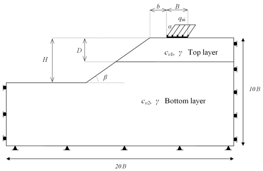
Figure 1 presents the geometrical layout of a strip footing-slope configuration. A strip footing of width B is located on a stratified soil profile consisting of two distinct layers and experiences a uniformly distributed load inclined at angle α measured from the vertical direction. The system geometry is characterized through the following normalized parameters: the setback ratio b/B (representing the horizontal distance from the foundation edge to the slope crest), the normalized slope height H/B, the slope inclination angle β, the thickness ratio of the upper soil layer D/B, and the dimensionless strength ratios cu1/γB and cu2/γB. In these expressions, γ signifies the soil unit weight, whereas cu1 and cu2 correspond to the undrained shear strength values of the upper and lower soil strata, respectively.
The dimensionless parameter cu1/γB represents the ratio of the undrained shear strength of the upper layer cu1 to the overburdened stress scale γB, where γ is the unit weight of the soil and B is the foundation width. This parameter controls the relative importance of soil cohesion with respect to the self-weight of the soil mass and governs the transition between cohesion-dominated and weight-dominated failure mechanisms. Low values of cu1/γB correspond to soft cohesive soils or wide foundations, while high values correspond to stiff clays or narrow foundations.

3. Finite Element Limit Analysis Model

Finite element limit analysis (FELA) integrates classical limit theorems from plasticity theory with finite element discretization to establish rigorous bounds on the ultimate bearing capacity. This approach generates two distinct bracketing solutions: the upper bound (UB) solution, obtained through kinematically admissible velocity fields, which furnishes an upper estimate of the failure load; whereas the lower bound (LB) solution, derived from statically admissible stress fields, which provides a lower estimate. Importantly, these two approaches constrain the actual bearing capacity within a definable range without necessitating predetermined failure mechanisms.
Wide use of the FELA method in geotechnical engineering [9,13,16,21,27,28,29,30] is noticed in recent years due to its high efficiency and precision. Optum G2 (V2023) based on the FELA method has been published [27]. The generation of the mesh is refined to meet the demand for efficiency and precision [21,31] and to ensure the precision of the modeling in this study. A mesh convergence study was performed using adaptive refinement. A total of five adaptive iterations were carried out, leading to a final mesh of approximately 5000 elements. Convergence was achieved with variations in the bearing capacity below 1% between successive refinement stages. The authors of [16,21] showed that a slope height greater than 3B does not have a significant effect on the value of the bearing capacity. In our study the normalized slope height H/B is fixed at 3. Additionally, Merifield et al. [32] investigated the bearing capacity of a strip footing resting on a two-layer clay deposit with a horizontal ground surface and proposed a modified bearing-capacity factor N c * , which can be expressed as:
N c * = q u   c u 1
where q u = q u i c o s ( α ) represents the vertical component of the applied load at failure (i.e., the maximum vertical load per unit area at failure), and cu1 is the undrained shear strength of the upper soil layer. In the present study, this definition is extended to the case of a two-layer slope subjected to an inclined load, and the dimensionless bearing capacity factor Nci is defined accordingly.
The normalization by cu1 is adopted consistently with Merifield et al. [32] and Xiao et al. [21], as the upper layer directly governs the local failure initiation beneath the foundation. This choice ensures direct comparability with existing solutions and provides a practical and convenient reference parameter for design applications.
The undrained soil bearing capacity subjected to inclined loading for this problem can be rewritten as:
N c i = q u   ( v e r t i c a l ) c u 1 = f β , D B , c u 1 γ B , c u 1 c u 2 , b B , α
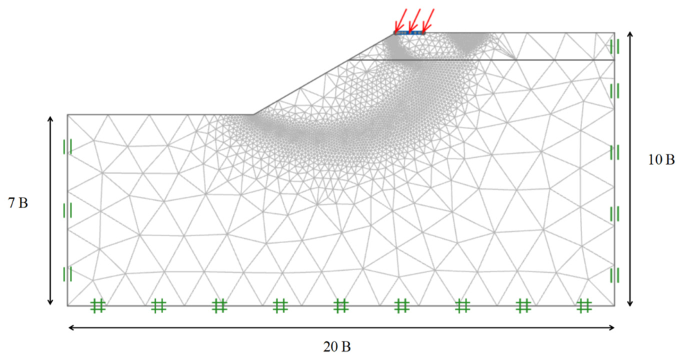
This study examines a comprehensive range of geotechnical and geometric parameters representative of real engineering conditions. The analyzed configurations include three characteristic slope angles (15°, 30°, and 45°), along with an extensive set of dimensionless ratios covering geometry (D/B, b/B) and normalized soil strength (cu1/γB, cu1/cu2). The load inclination angle α, measured from the vertical direction, varies between 0° and 25° in increments of 5°, consistent with typical values encountered in practice. This parametric approach enables the reproduction of various geotechnical scenarios, including two-layer soil profiles where the upper layer may be stronger (cu1/cu2 > 1) or weaker than the lower layer. Realistic boundary constraints are incorporated into the numerical model, with fixed conditions applied at the base and horizontal fixity imposed on the lateral edges. Soil characteristics include a unit weight γ equal to 20 kN/m3, with undrained behavior represented by the Tresca yield criterion. The footing-soil interface is modeled as fully rough, which is represented by a unit contact factor in the Optum G2 software. Strip footings are represented by rigid, weightless elements, thereby isolating and specifically analyzing the soil-foundation interaction. This methodology ensures the consistent simulation of shallow foundation behavior under various slope configurations, soil properties, and loading conditions, in accordance with current standards in geotechnical engineering research. Figure 2 presents the developed numerical model and its main characteristics.
It is noted that the present parametric study focuses on the bearing capacity of strip foundations on inherently stable two-layer slopes, i.e., slopes for which the factor of safety against slope failure F = N0 × cu/(γH) >> 1 in the absence of foundation loading (Taylor, 1937; Bishop, 1955; Janbu, 1954) [33,34,35]. This assumption ensures that the slope remains inherently stable and that the computed failure mechanisms are primarily governed by footing loading rather than global slope instability.
Only slopes satisfying F 1 are considered in order to isolate foundation-induced failure mechanisms. Under this condition, the failure mechanism is governed by the foundation–soil interaction, and the normalized strength parameter cu/(γB) is the relevant dimensionless group controlling the bearing capacity. The slope height H is assumed sufficiently large relative to the foundation width B; as such, the boundary effects on the failure mechanism are negligible.

4. Comparison with Prior Studies

4.1. Strip Footing on Horizontal Two-Layer Clay

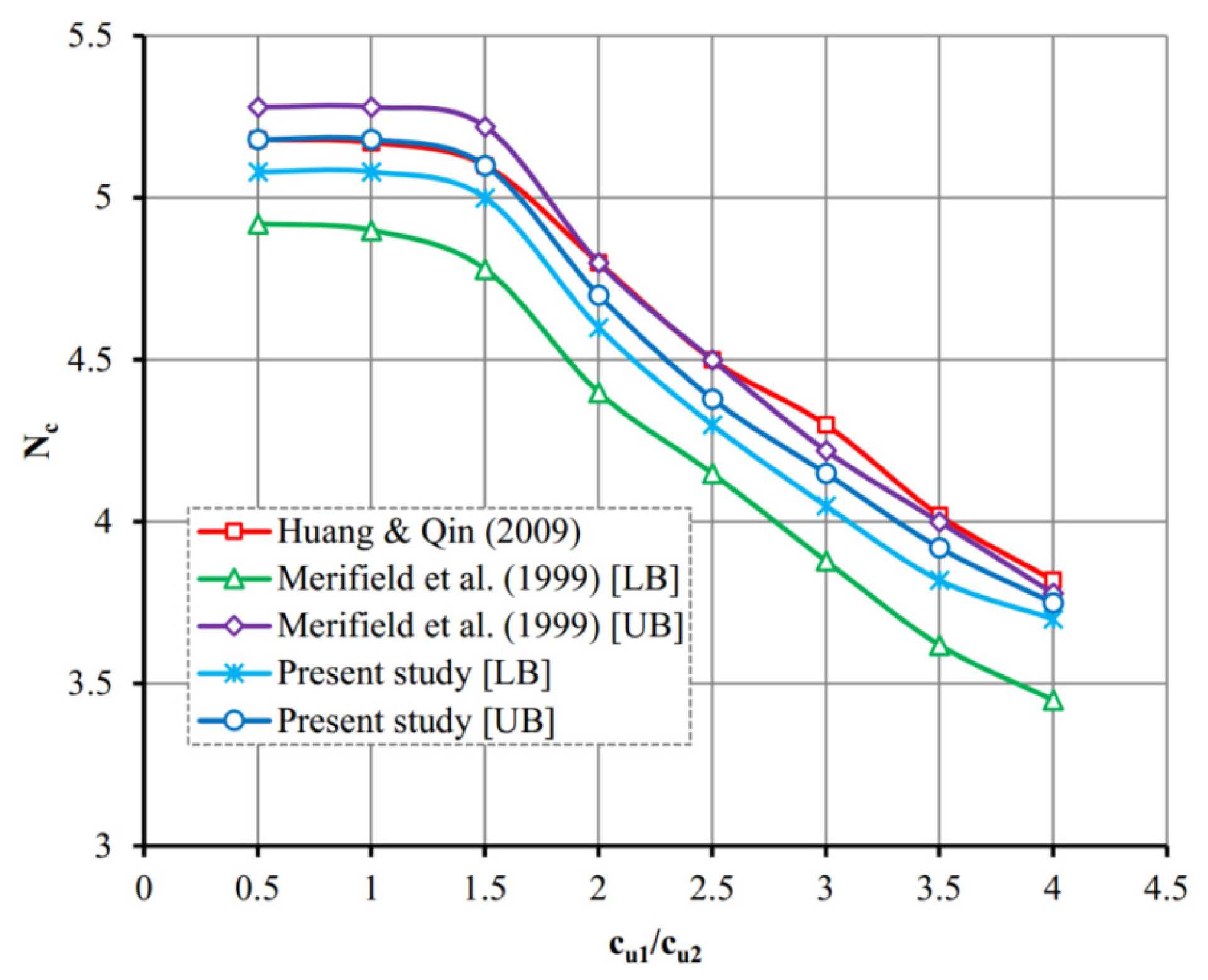
The present results for a strip footing resting on horizontal two-layer clay were validated against the FELA method by Merifield et al. [32] and the multi-rigid block upper bound (UB) solution by Huang and Qin [36]. Figure 3 presents how the modified bearing capacity factor Nc varies with the undrained shear strength ratio cu1/cu2. As depicted in Figure 3, the UB results from this study exhibit excellent agreement with the multi-rigid block UB solution reported by Huang and Qin. The current solution also demonstrates reasonable consistency with the findings of Merifield et al. [32]. However, the FELA method by Merifield et al. [32] yielded slightly higher results compared to the present analysis. This deviation is due to the adoption of an adaptive remeshing algorithm in the current analysis.

4.2. Strip Footing at Slope Crest on Uniform Slope

The proposed solutions for foundations on two-layer slopes with varying cu/γB, cu1/cu2, and D/B ratios were compared against the results of Xiao et al. [21], as presented in Table 1. The outcomes of both studies show close agreement, with the largest relative error of 1.19% recorded when cu/γB = 8, D/B = 0.5, and cu1/cu2 = 0.5.

5. Results and Interpretation

This section analyzes the effect of the principal parameters introduced in Equation (2) on the inclined load-bearing capacity factor Nci for undrained conditions. The numerical results are displayed in graphical form (Figure 4, Figure 5, Figure 6, Figure 7, Figure 8, Figure 9, Figure 10, Figure 11 and Figure 12) to ensure ease of practical application.

5.1. Influence of Upper Layer Normalized Shear Strength Parameter (cu1/γB)

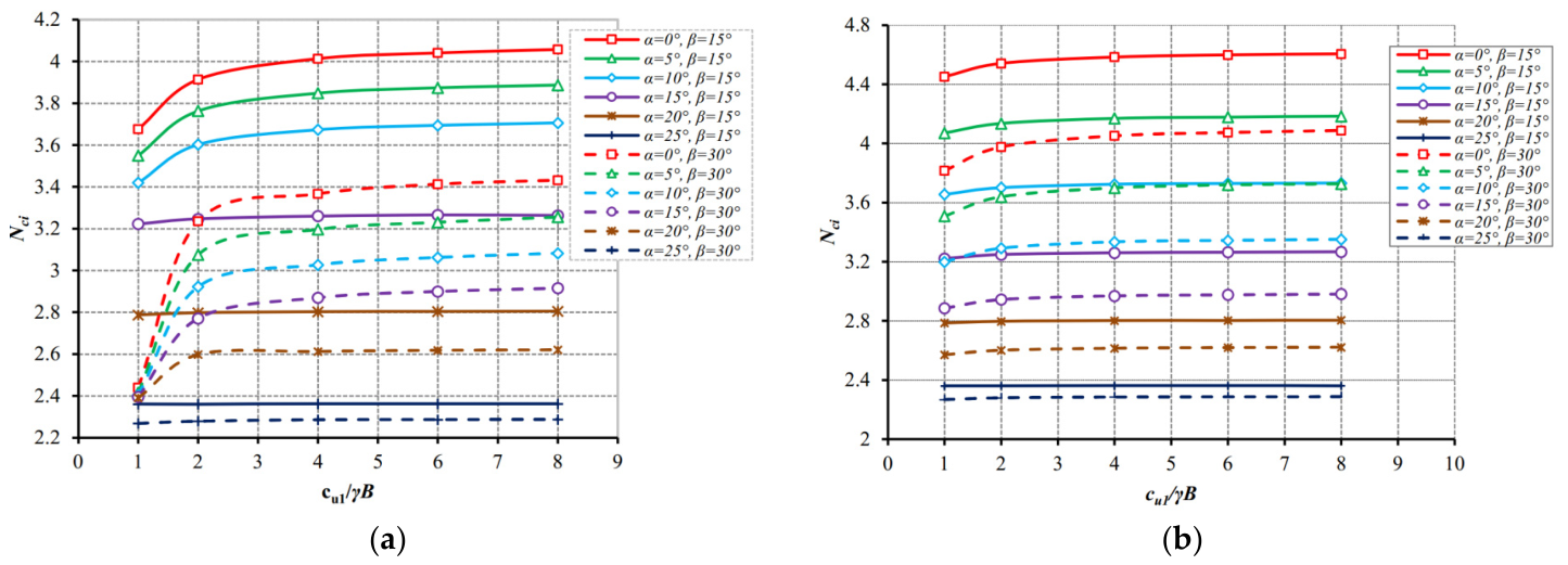
Figure 4 shows that for D/B = 0.75 at slope angles β = 15° and 30° and how the bearing capacity factor Nci varies with cu1/γB and α. Two-layer configurations are examined: cu1/cu2 = 0.5 (weak upper layer on strong lower layer) and cu1/cu2 = 1.5 (strong upper layer on weak lower layer). As expected, Nci values tend to increase with cu1/γB in all cases. The curves flatten when cu1/γB > 4, suggesting that higher cu1/γB values have a diminishing impact on slope bearing capacity, consistent with observations in Figure 4b. This convergence pattern is less pronounced at lower cu1/γB values.
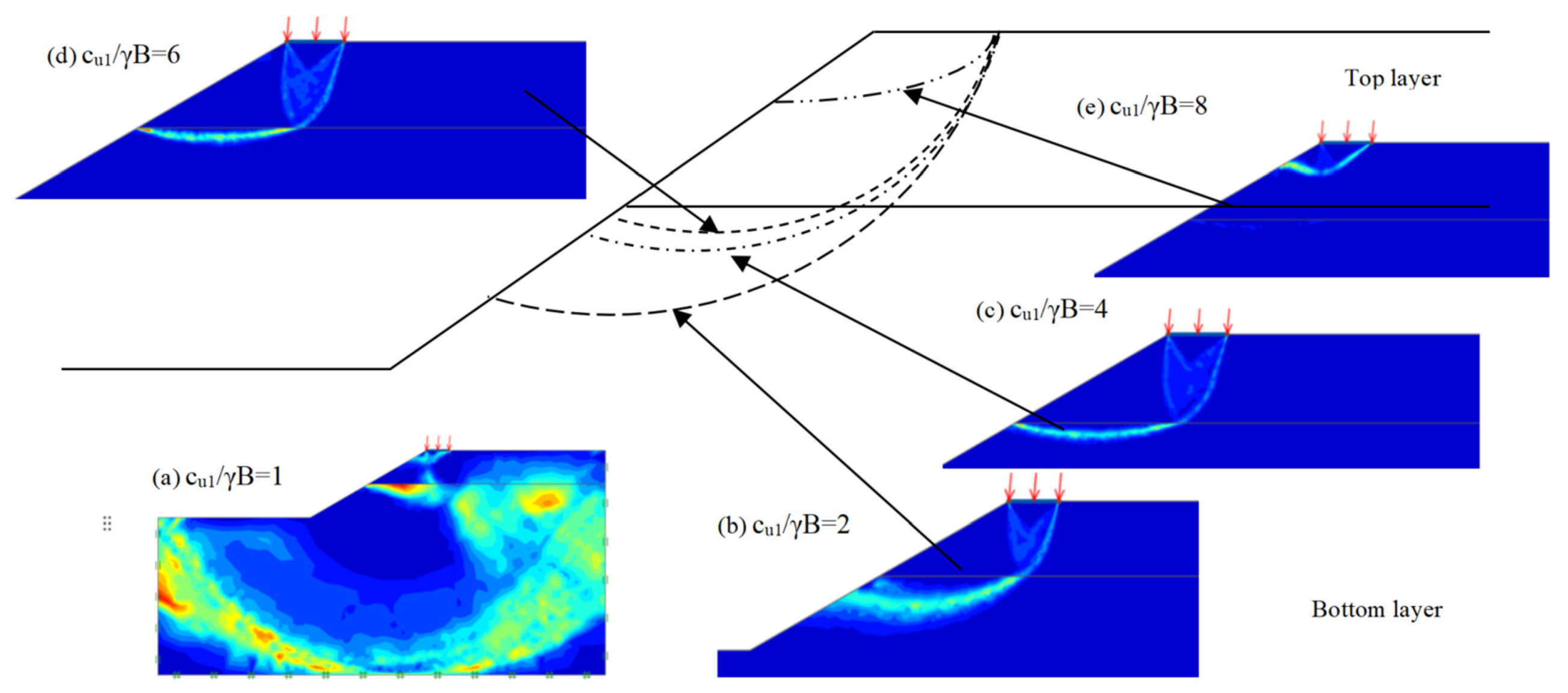
Figure 5 presents the influence of cu1/γB on failure mechanisms. Strip footings on two-layer slopes exhibit two principal failure mechanisms. It is worth noting that the global failure mode (observed in Figure 5a) arises specifically for low values of cu1 and cu2, where the insufficient shear strength of both layers triggers a full-domain failure propagating from the foundation base through the entire slope system, regardless of the model size. The second mechanism is localized foundation failure, characterized by a failure surface propagating from the footing to the slope face. In two-layer slope configurations, four failure sub-categories emerge depending on the slip line position. As shown in Figure 5e, when the slip line remains entirely within the upper layer, the lower layer plays no role in system behavior, suggesting that the upper layer strength is sufficient. Figure 5d reveals the slip line reaching the inter-layer boundary with its endpoint at this interface, allowing the lower layer to potentially contribute to shear resistance. The further downward extension of the slip line along the slope surface allows increased mobilization of lower layer bearing capacity. Figure 5b captures the critical scenario where the slip line penetrates the lower layer, maximizing the lower layer’s contribution to resisting external loads. Reduced cu1/γB values trigger a transition to global slope failure, as illustrated in Figure 5a.

5.2. Influence of the Inclined Loading Angle α

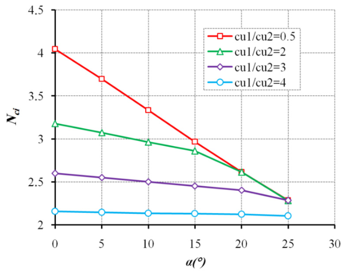
The influence of the Inclined Loading angle α on bearing capacity is examined through Figure 6, which shows the evolution of Nci versus α for an embedment ratio D/B = 1 and slope angle β = 30°. The approximately linear nature of these curves demonstrates an approximately linear relationship between Nci and α. The rate of the bearing capacity reduction is more pronounced when cu1/cu2 < 1 than when cu1/cu2 > 1.
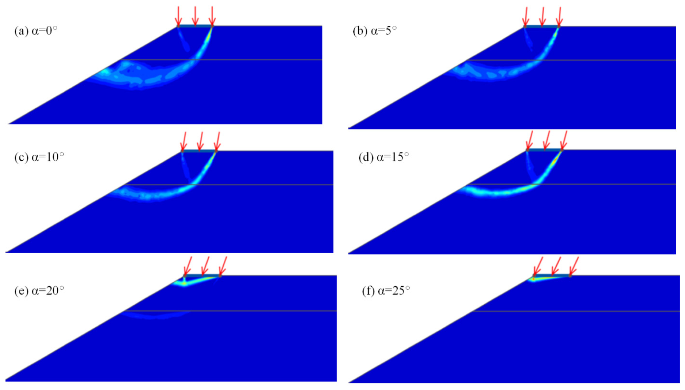
Figure 7 shows the upper bound failure patterns for β = 30°, D/B = 1, cu1/cu2 = 2, and cu1/γB = 4 with varying load inclination (α = 0° to 25° at 5° increments). A triangular wedge develops under the foundation, progressively shifting in the direction of the inclined loading as α increases. This is consistent with a significant influence of loading angle on the failure mechanism geometry. As anticipated, increasing inclination angles cause the failure zone to migrate toward the footing base, which may eventually lead to foundation sliding.

5.3. Effect of Slope Inclination β

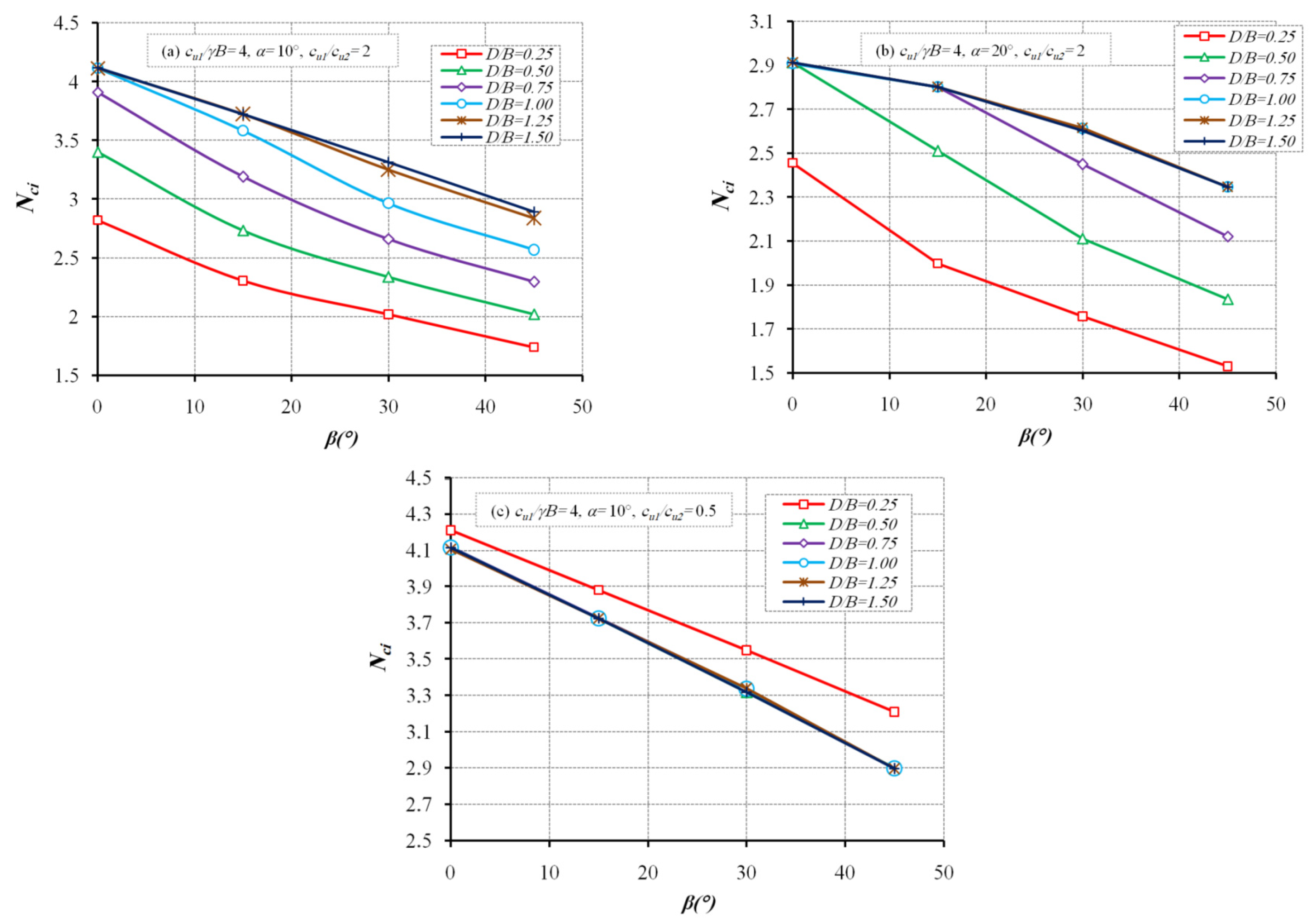
Figure 8 shows the evolution of the bearing capacity factor Nci with respect to slope angle β (0° to 45°) and embedment ratio D/B for a normalized shear strength cu1/γB = 4. Bearing capacity decreases progressively with steeper slopes, which is consistent with reduced passive resistance and lateral confinement, as reflected in the shallower failure mechanisms observed. A slope angle of β = 30° is therefore used as the baseline configuration for the subsequent parametric investigations.

5.4. Effect of Upper Layer Thickness Ratio (D/B)

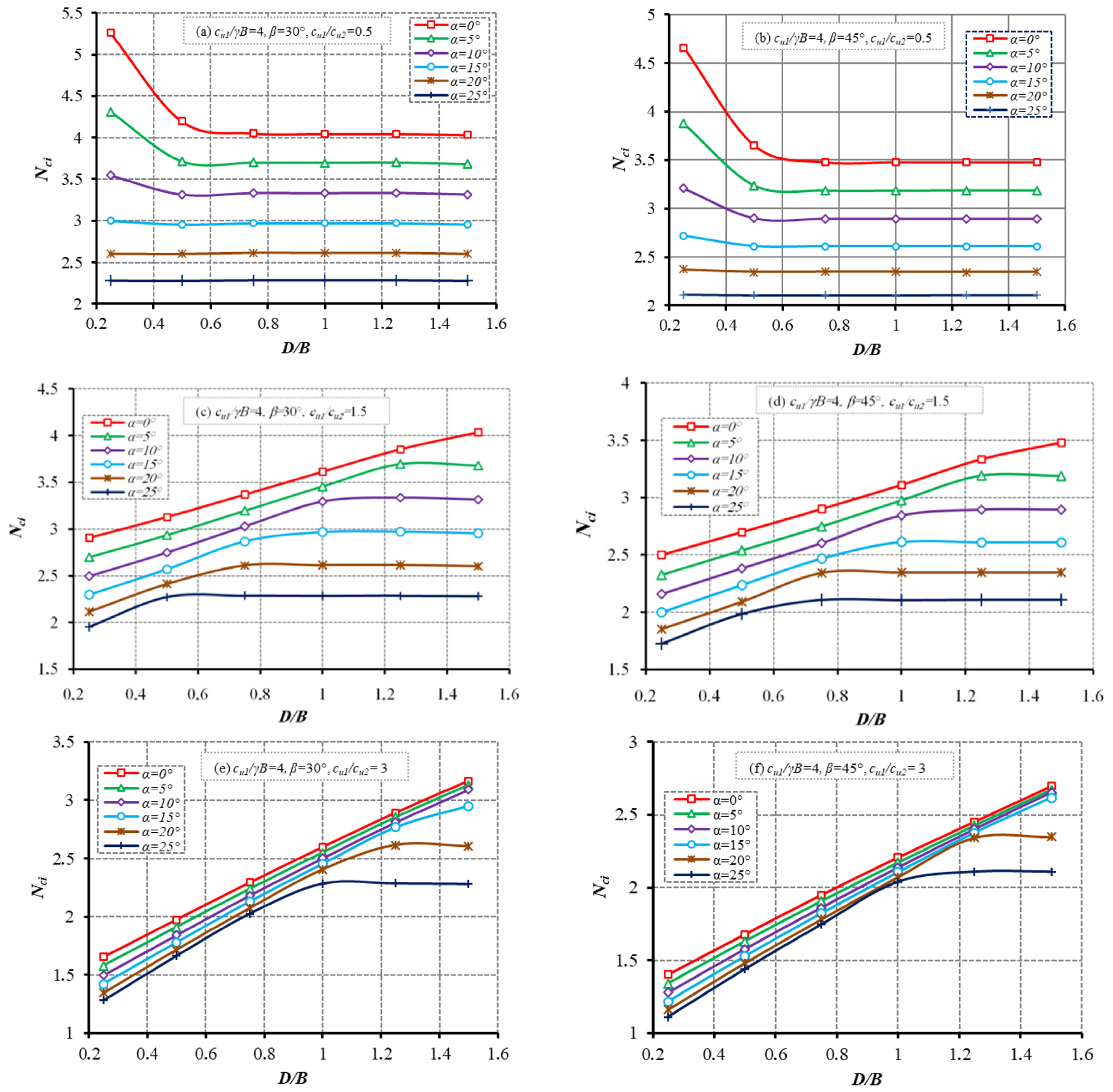
The upper layer thickness effect is analyzed in this section. Figure 9 shows the results for varying D/B and α when cu1/γB = 4 for cu1/γB = 4, considering various cu1/cu2 and β parameters. Figure 9a,b show that curves become nearly flat for α ≥ 10°, confirming that upper layer thickness has minimal impact on the bearing capacity when the upper layer is weaker (cu1/cu2 < 1). Figure 9c,d reveal that curves for α between 10° and 25° plateau as D/B increases, indicating that Nci values approach limiting values at higher inclination angles. Slope angle variations produce distinct responses, as observed between Figure 9c,d. Figure 9c–f demonstrate that smaller cu1/cu2 ratios result in earlier convergence to maximum bearing capacity.
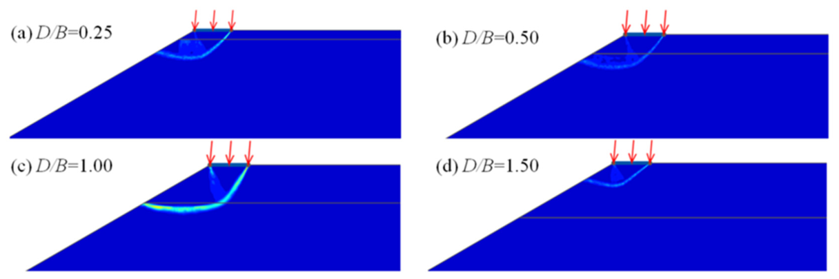
Figure 10 depicts the evolution of failure patterns with varying D/B ratios. Figure 10a–c demonstrate that failure surfaces penetrate the lower layer and tend to migrate toward the inter-layer boundary as D/B increases. At D/B = 1.5; however, the failure surface is entirely contained within the top layer, confirming that the lower layer does not affect the bearing capacity under these conditions. When cu1/cu2 > 1 (firm clay over soft clay), the upper layer controls the failure mechanism. Consequently, the bearing capacity becomes desensitized to upper layer thickness beyond a critical value where ultimate capacity is mobilized.

5.5. Influence of Interlayer Strength Ratio cu1/cu2 on Failure Mechanisms

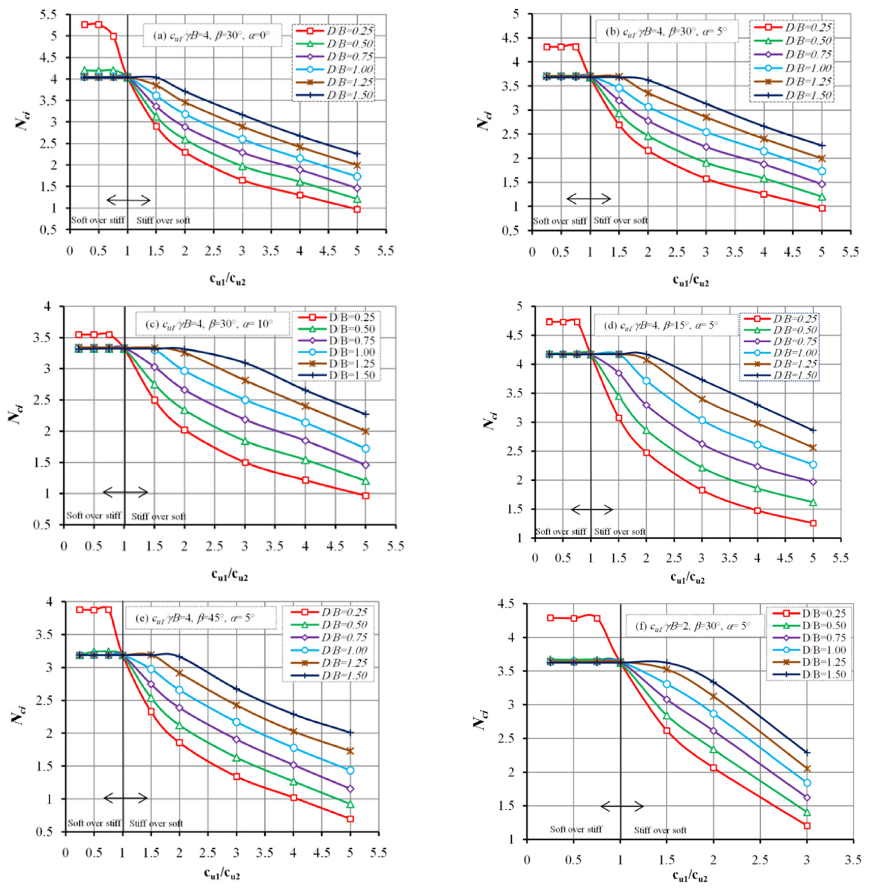
Figure 11 presents the factor of the bearing capacity Nci as a function of cu1/cu2 and D/B ratios. For cases where cu1/cu2 ≤ 1, the curves remain essentially horizontal, indicating that the lower layer possesses sufficient strength to prevent failure. In this configuration, failure mechanisms concentrate exclusively within the upper layer (Figure 12). Conversely, when cu1/cu2 increases beyond 1, the bearing capacity progressively decreases. This trend is consistent with the relative weakening of the lower layer, whose influence appears to intensify with increasing cu1/cu2 ratio. However, this effect attenuates considerably for high D/B values, as the increased thickness of the upper layer enhances its contribution to overall bearing capacity, thereby reducing the influence of the underlying layer. From a practical standpoint, particular attention must be given to configurations with thin upper layers, which are more susceptible to failure.
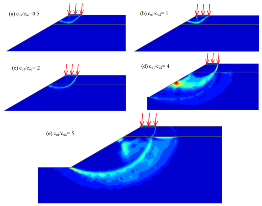
Figure 12 illustrates upper bound (UB) failure mechanisms for different cu1/cu2 ratios at β = 30°, α = 5°, cu1/γB = 4, and D/B = 0.75. When cu1/cu2 ≤ 1, the lower layer exhibits sufficient strength to confine failure exclusively within the upper layer (Figure 12a,b). However, for cu1/cu2 > 1, failure surfaces progressively extend into the lower layer and migrate toward the slope toe as the ratio increases (Figure 12c,d). This propagation is consistent with the relative weakening of the lower layer, which appears to limit the mobilization of its shear capacity. At elevated cu1/cu2 values, this process may lead to a global failure mode (Figure 12e).

5.6. Effect of Strip Footing Setback Distance (b/B)

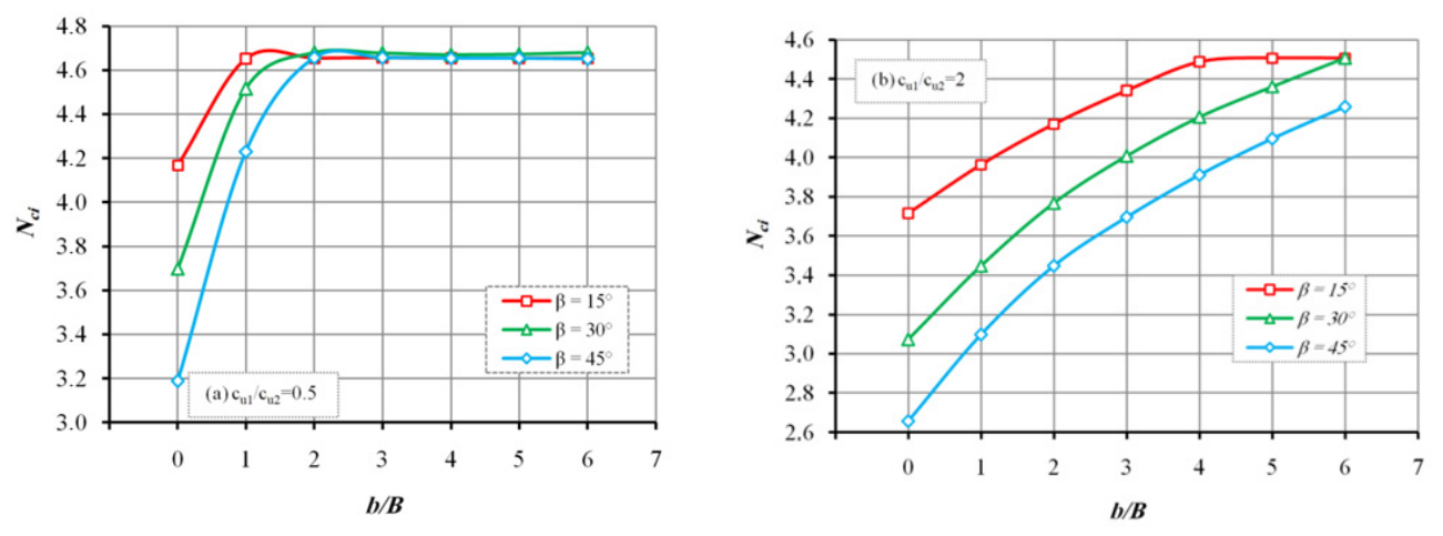
The impact of varying the horizontal setback distance of the strip foundation is examined in Figure 13, using parameters cu1/γB = 4 and D/B = 1. Results show that the bearing capacity increases with the b/B ratio. This upward trend gradually levels off until the curves flatten, suggesting that beyond a certain point, the slope exerts minimal influence on foundation performance. To better define this transition, the notion of critical setback distance is presented in Figure 14.
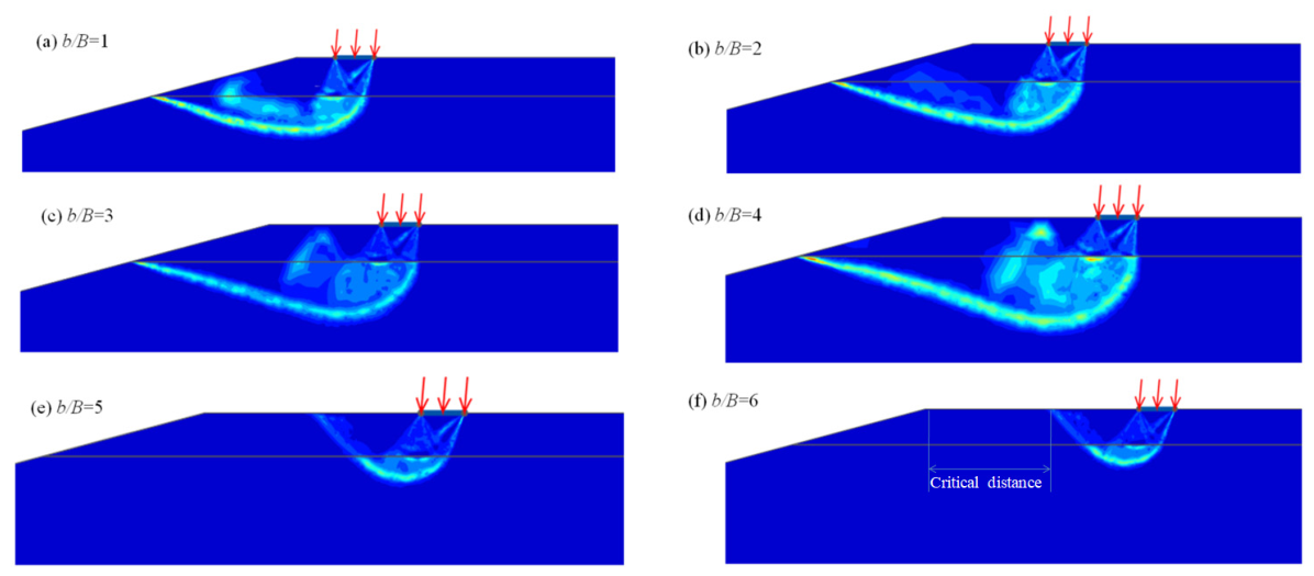
Figure 14 displays the shear failure patterns derived from upper bound (UB) limit analysis across different b/B ratios, maintaining β = 15°, D/B = 1, and cu1/γB = 4 (as shown in Figure 13b). The findings demonstrate that when b/B remains below 5, the failure planes extend through the base of the upper soil layer. Conversely, when this ratio exceeds 5, the failure mechanism shifts entirely away from the slope face. This suggests that, for the analyzed conditions, the influence of foundation loading on slope stability becomes negligible when b / B exceeds approximately 5, indicating a critical setback distance beyond which slope–footing interaction is expected to be limited.
For the analyzed conditions (β = 15°, D/B = 1, cu1/γB = 4), the slope influence on the bearing capacity becomes negligible beyond a normalized setback distance of approximately b/B = 5. It should be noted that this critical value is specific to the parametric combination considered and may vary significantly with slope angle, embedment depth, and soil strength properties.
For low values of b / B , particularly when c u 1 / c u 2 < 1 , the failure mechanism may remain confined within the upper layer, limiting its interaction with the slope face. Under these conditions, the influence of the slope angle becomes less pronounced.

6. Practical Recommendations and Future Research Directions

Based on the results of the present study, engineers dealing with strip foundations on two-layer cohesive slopes under inclined loading are advised to carefully account for the combined effects of load inclination angle, interlayer shear strength ratio, and setback distance in design, as these parameters are shown to have a pronounced influence on the bearing capacity and failure mode. The design tables provided in this study can be used directly for preliminary estimation of Nci under various geometric and loading configurations, reducing the need for full numerical analysis at early design stages.
Several directions are identified for future research to extend the present findings. These include: (i) the extension to three-dimensional configurations for rectangular and circular foundations; (ii) the incorporation of seismic loading using pseudo-static or dynamic approaches; (iii) the investigation of geosynthetic-reinforced two-layer slopes; (iv) physical model testing or centrifuge experiments to provide experimental benchmarks; and (v) the development of machine learning-based predictive models trained on the dataset generated in this study.

7. Conclusions

The present investigation explores the undrained bearing capacity of strip foundations resting on two-layer slope configurations using the finite element limit analysis (FELA) methodology. The parametric investigation encompasses the influence of several geometric and mechanical variables, including loading inclination (α), normalized upper layer thickness (D/B), interlayer shear strength ratio (cu1/cu2), normalized strength factor (cu1/γB), and slope angle (β). Comprehensive design charts are provided to facilitate practical implementation, accompanied by detailed analysis of failure mechanisms. Based on the results, the following conclusions can be drawn:
  • When cu1/cu2 < 1, the slope angle β exerts a nearly linear influence on the bearing capacity factor Nci, whereas for cu1/cu2 > 1, this influence diminishes progressively with increasing β.
  • In all cases examined the factor of the bearing capacity Nci decreases with increasing load inclination angle α. Furthermore, α exhibits anapproximately linear influence on Nci, with its impact on the bearing capacity becoming more pronounced as the strength ratio cu1/cu2 decreases.
  • When the top layer is weaker than the bottom layer (cu1/cu2 < 1), the bearing capacity decreases by increasing normalized thickness D/B until stabilizing at an asymptotic value. Conversely, for cu1/cu2 > 1, the bearing capacity increases progressively with D/B before reaching a plateau. This threshold value is attained more rapidly for high values of load inclination α, slope angle β, and strength ratio cu1/cu2.
  • Increasing the strength ratio cu1/cu2 reduces the bearing capacity, with the magnitude of this reduction amplifying as the normalized upper layer thickness D/B decreases.
  • Nci increases nonlinearly with cu1/γB at a diminishing rate. Higher cu1/γB values also reduce the influence of the lower layer.
  • Failure surfaces for cu1/cu2 < 1 remain confined to the upper layer. Conversely, for cu1/cu2 > 1, the failure surfaces extend progressively toward the toe of the slope as the strength ratio cu1/cu2 increases. The depth of the failure zone decreases with decreasing cu1/γB or increasing cu1/cu2, and also undergoes horizontal displacement due to load inclination.
  • The setback distance from the slope crest exhibits a direct proportional relationship with bearing capacity enhancement. The destabilizing influence of the slope attenuates gradually as the foundation-to-slope distance increases, particularly for configurations characterized by high undrained strength ratios (cu1/cu2) and low slope inclinations.
It should be noted that the results and design charts presented in this study are derived from numerical analyses based on the finite element limit analysis method, under idealized assumptions including uniform undrained shear strength within each layer, plane strain conditions, and perfectly plastic soil behavior. While the numerical model has been validated against published results from the literature, the conclusions should be interpreted with appropriate caution when applied to real-world conditions involving soil heterogeneity, anisotropy, and three-dimensional effects. Physical model testing and/or field experiments on instrumented foundations near layered slopes would be highly valuable to further validate the proposed framework and are identified as an important direction for future research. The results should therefore be interpreted within the framework of the adopted assumptions.

Author Contributions

Conceptualization, F.K.; Methodology, F.K.; Software, F.K. and D.D.; Validation, A.H.; Formal analysis, F.K.; Investigation, F.K.; Writing—original draft, F.K.; Writing—review & editing, A.H., D.D. and M.S.; Supervision, A.H., D.D. and M.S. All authors have read and agreed to the published version of the manuscript.

Funding

This research received no external funding.

Institutional Review Board Statement

Not applicable.

Informed Consent Statement

Not applicable.

Data Availability Statement

The data presented in this study are available on request from the corresponding author due to privacy.

Conflicts of Interest

The authors declare no conflicts of interest.

References

  1. Hansen, J.B. A General Formula for Bearing Capacity; Bulletin No. 11; Danish Geotechnical Institute: Copenhagen, Denmark, 1961. [Google Scholar]
  2. Vesic, A.S. Bearing capacity of shallow foundations. In Foundation Engineering Handbook; Van Nostrand Reinhold: New York, NY, USA, 1975. [Google Scholar]
  3. Azzouz, A.S.; Baligh, M.M. Loaded areas on cohesive slopes. J. Geotech. Eng. 1983, 109, 724–729. [Google Scholar] [CrossRef] [Scilit]
  4. Meyerhof, G.G. The ultimate bearing capacity of foundations on slopes. In Proceedings of the 4th International Conference on Soil Mechanics and Foundation Engineering (ICSMFE), London, UK, 12–16 August 1957; Volume 1, pp. 384–386. [Google Scholar]
  5. Narita, K.; Yamaguchi, H. Bearing capacity analysis of foudations on slopes by use of log-spiral sliding surfaces. Soils Found. 1990, 30, 144–152. [Google Scholar] [CrossRef] [Scilit] [PubMed]
  6. Graham, J.; Andrews, M.; Shields, D.H. Stress characteristics for shallow footings in cohesionless slopes. Can. Geotech. J. 1988, 25, 238–249. [Google Scholar] [CrossRef] [Scilit]
  7. Sokolovskii, V.V. Statics of Granular Media; Elsevier: Amsterdam, The Netherlands, 2016. [Google Scholar]
  8. Davis, E.H.; Booker, J.R. Some adaptations of classical plasticity theory for soil stability problems. In the Proceedings of the Symposium on the Role of Plasticity in Soil Mechanics, Cambridge, UK, 13–15 September 1973. [Google Scholar]
  9. Georgiadis, K. Undrained bearing capacity of strip footings on slopes. J. Geotech. Geoenviron. Eng. 2010, 136, 677–685. [Google Scholar] [CrossRef] [Scilit]
  10. Kusakabe, O.; Kimura, T.; Yamaguchi, H. Bearing capacity of slopes under strip loads on the top surfaces. Soils Found. 1981, 21, 29–40. [Google Scholar] [CrossRef] [Scilit]
  11. Georgiadis, K. The influence of load inclination on the undrained bearing capacity of strip footings on slopes. Comput. Geotech. 2010, 37, 311–322. [Google Scholar] [CrossRef] [Scilit]
  12. Lafifi, B.; Hamrouni, A.; Khoualdia, T.; Gheris, A.; Rouaiguia, A. Prediction and optimization of the bearing capacity of strip footing resting on soft soil improved with stone columns using RSM, ANN, and multi-objective GA. Innov. Infrastruct. Solut. 2024, 9, 146. [Google Scholar] [CrossRef] [Scilit]
  13. Shiau, J.S.; Merifield, R.S.; Lyamin, A.V.; Sloan, S.W. Undrained stability of footings on slopes. Int. J. Geomech. 2011, 11, 381–390. [Google Scholar] [CrossRef] [Scilit]
  14. Leshchinsky, B. Bearing capacity of footings placed adjacent to c′-ϕ′ slopes. J. Geotech. Geoenviron. Eng. 2015, 141, 04015022. [Google Scholar] [CrossRef] [Scilit]
  15. Leshchinsky, B.; Xie, Y. Bearing capacity for spread footings placed near c′-ϕ′ slopes. J. Geotech. Geoenviron. Eng. 2017, 143, 06016020. [Google Scholar] [CrossRef] [Scilit]
  16. Zhou, H.; Zheng, G.; Yin, X.; Jia, R.; Yang, X. The bearing capacity and failure mechanism of a vertically loaded strip footing placed on the top of slopes. Comput. Geotech. 2018, 94, 12–21. [Google Scholar] [CrossRef] [Scilit]
  17. Lyamin, A.V.; Krabbenhøft, K.; Sloan, S.W. Limit analysis of bearing capacity of eccentrically loaded strip footing on clay with tension cut-off interface conditions. In Proceedings of the 1st International Symposium on Computational Geomechanics, COMGEO I, Juan-les-Pins, France, 29 April–1 May 2009; pp. 701–708. [Google Scholar]
  18. SalimiEshkevari, S.; Abbo, A.J.; Kouretzis, G. Bearing capacity of strip footings on sand over clay. Can. Geotech. J. 2019, 56, 699–709. [Google Scholar] [CrossRef] [Scilit]
  19. Shiau, J.S.; Lyamin, A.V.; Sloan, S.W. Bearing capacity of a sand layer on clay by finite element limit analysis. Can. Geotech. J. 2003, 40, 900–915. [Google Scholar] [CrossRef] [Scilit]
  20. Vali, R.; Beygi, M.; Saberian, M.; Li, J. Bearing capacity of ring foundation due to various loading positions by finite element limit analysis. Comput. Geotech. 2019, 110, 94–113. [Google Scholar] [CrossRef] [Scilit]
  21. Xiao, Y.; Zhao, M.; Zhang, R.; Zhao, H.; Wu, G. Undrained bearing capacity of strip footings placed adjacent to two-layered slopes. Int. J. Geomech. 2019, 19, 06019014. [Google Scholar] [CrossRef] [Scilit]
  22. Keshavarz, A.; Beygi, M.; Vali, R. Undrained seismic bearing capacity of strip footing placed on homogeneous and heterogeneous soil slopes by finite element limit analysis. Comput. Geotech. 2019, 113, 103094. [Google Scholar] [CrossRef] [Scilit]
  23. Hamza, O.; De Vargas, T.; Boff, F.E.; Hussain, Y.; Davies-Vollum, K.S. Geohazard Assessment of Landslides in South Brazil: Case Study. Geotech. Geol. Eng. 2020, 38, 971–984. [Google Scholar] [CrossRef] [Scilit]
  24. Hamza, O.; Kourdey, A.; Hussain, Y.; Mawas, A.-H. Evaluation of the Subgrade Reaction for closely-spaced raft and isolated foundations on sand—Case study. Proc. Inst. Civ. Eng.—Geotech. Eng. 2022, 177, 135–167. [Google Scholar] [CrossRef] [Scilit]
  25. Michalowski, R.L. Stability Charts for Uniform Slopes. J. Geotech. Geoenviron. Eng. 2002, 128, 351–355. [Google Scholar] [CrossRef] [Scilit]
  26. Huang, C.C.; Chen, Y.W. Bearing capacity of free-rotating and restrained footings near slopes. J. Geoengin. 2019, 14, 1–10. [Google Scholar] [CrossRef]
  27. Krabbenhoft, K.; Lyamin, A.; Krabbenhoft, J. OptumG2, V2023; Computer Software; Optum Computational Engineering: Copenhagen, Denmark, 2015.
  28. Merifield, R.S.; Sloan, S.W.; Yu, H.S. Stability of plate anchors in undrained clay. Géotechnique 2001, 51, 141–153. [Google Scholar] [CrossRef]
  29. Xiao, Y.; Zhao, M.; Zhao, H. Undrained stability of strip footing above voids in two-layered clays by finite element limit analysis. Comput. Geotech. 2018, 97, 124–133. [Google Scholar] [CrossRef] [Scilit]
  30. Wu, G.; Zhao, H.; Zhao, M.; Xiao, Y. Undrained seismic bearing capacity of strip footings lying on two-layered slopes. Comput. Geotech. 2020, 122, 103539. [Google Scholar] [CrossRef] [Scilit]
  31. Qian, Z.G.; Li, A.-J.; Merifield, R.S.; Lyamin, A.V. Slope stability charts for two-layered purely cohesive soils based on finite-element limit analysis methods. Int. J. Geomech. 2015, 15, 06014022. [Google Scholar] [CrossRef] [Scilit]
  32. Merifield, R.S.; Sloan, S.W.; Yu, H.S. Rigorous plasticity solutions for the bearing capacity of two-layered clays. Geotechnique 1999, 49, 471–490. [Google Scholar] [CrossRef] [Scilit]
  33. Taylor, D.W. Stability of Earth Slopes. J. Boston Soc. Civ. Eng. 1937, 24, 197–246. [Google Scholar]
  34. Bishop, A.W. The use of the slip circle in the stability analysis of slopes. Géotechnique 1955, 5, 7–17. [Google Scholar] [CrossRef] [Scilit]
  35. Janbu, N. Application of composite slip surfaces for stability analysis. In Proceedings of the European Conference on Stability of Earth Slopes, Stockholm, Sweden, 20–25 September 1954; Volume 3, pp. 43–49. [Google Scholar]
  36. Huang, M.; Qin, H.-L. Upper-bound multi-rigid-block solutions for bearing capacity of two-layered soils. Comput. Geotech. 2009, 36, 525–529. [Google Scholar] [CrossRef] [Scilit]
Figure 1. Schematic representation of the foundation-slope-soil system.
Geotechnics 06 00042 g001
Figure 2. Numerical model in Optum G2 showing a strip footing positioned on a two-layer soil slope.
Geotechnics 06 00042 g002
Figure 3. Comparison of Nc values with respect to cu1/cu2 for D/B = 1 [32,36].
Geotechnics 06 00042 g003
Figure 4. Influence of normalized shear strength (cu1/γB), slope angle (β), and load inclination (α) on Nci for an embedment ratio D/B = 0.75: (a) cu1/cu2 = 0.5; (b) cu1/cu2 = 1.5.
Geotechnics 06 00042 g004
Figure 5. Upper bound failure mechanisms for varying normalized shear strength (cu1/γB) with β = 30°, α = 5°, cu1/cu2 = 2, and D/B = 1.5: (a) cu1/γB = 1; (b) cu1/γB = 2; (c) cu1/γB = 4; (d) cu1/γB = 6; (e) cu1/γB = 8.
Geotechnics 06 00042 g005
Figure 6. Effect of load inclination α and shear strength ratio cu1/cu2 on bearing capacity factor Nci at β = 30°, cu1/γB = 4, and D/B = 1.
Geotechnics 06 00042 g006
Figure 7. Upper bound collapse mechanisms for different loading angle (α°) with β = 30°, D/B = 1, cu1/cu2 = 2, and cu1/γB = 2.
Geotechnics 06 00042 g007
Figure 8. Influence of slope angle β and upper layer thickness ratio D/B on the bearing capacity factor Nci for cu1/γB = 4: (a) cu1/cu2 = 2, α = 10°; (b) cu1/cu2 = 2, α = 20°; (c) cu1/cu2 = 0.5, α = 10°.
Geotechnics 06 00042 g008
Figure 9. Nci variation with α and D/B for cu1/γB = 4 at different cu1/cu2 and β values: (a) cu1/cu2 = 0.5, β = 30°; (b) cu1/cu2 = 1.5, β = 30°; (c) cu1/cu2 = 0.5, β = 45°; (d) cu1/cu2 = 1.5, β = 45°; (e) cu1/cu2 = 3, β = 30°; (f) cu1/cu2 = 3, β = 45°.
Geotechnics 06 00042 g009
Figure 10. Upper bound limit analysis failure modes under conditions of β = 30°, α = 5°, cu1/cu2 = 1.5, and normalized strength cu1/γB = 2, shown for four: (a) D/B = 0.25; (b) D/B = 0.5; (c) D/B = 1; and (d) D/B = 1.5.
Geotechnics 06 00042 g010
Figure 11. Influence of strength ratio cu1/cu2 and embedment ratio D/B on bearing capacity factor Nci for: (a) cu1/γB = 4, β = 30°, α = 0°; (b) cu1/γB = 4, β = 30°, α = 5°; (c) cu1/γB = 4, β = 30°, α = 10°; (d) cu1/γB = 4, β = 15°, α = 5°; (e) cu1/γB = 4, β = 45°, α = 5°; (f) cu1/γB = 2, β = 30°, α = 5°.
Geotechnics 06 00042 g011
Figure 12. Evolution of upper bound collapse mechanisms with increasing layer strength ratio cu1/cu2 (0.5 to 5) (ae) for fixed parameters: β = 30°, α = 5°, cu1/γB = 4, and D/B = 0.75.
Geotechnics 06 00042 g012
Figure 13. Effect of setback ratio b/B and slope inclination β on Nci for (a) cu1/cu2 = 0.5; (b) cu1/cu2 = 2.
Geotechnics 06 00042 g013
Figure 14. Collapse mechanisms obtained from upper bound analysis with β = 15°, D/B = 1, and cu1/γB = 4 for varying horizontal offsets: (a) b/B = 1; (b) b/B = 2; (c) b/B = 3; (d) b/B = 4; (e) b/B = 5; (f) b/B = 6.
Geotechnics 06 00042 g014
Table 1. Shows the evolution of the bearing capacity factor Nc for various combinations of normalized soil strength (cu1/γB), embedment ratio (D/B), and shear strength ratio (cu1/cu2) at a slope angle of 30°, compared with the results by Xiao et al. [21].
Nc (Our Study)Nc Xiao et al. [21]
cu1/γBcu1/cu2 = 0.5, D/B = 0.5cu1/cu2 = 0.5, D/B = 1.5cu1/cu2 = 1.5, D/B = 1.5cu1/cu2 = 1.5, D/B = 0.5cu1/cu2 = 0.5, D/B = 0.5cu1/cu2 = 0.5, D/B = 1.5cu1/cu2 = 1.5, D/B = 1.5cu1/cu2 = 1.5, D/B = 0.5
14.063.782.812.334.093.832.842.39
24.173.943.033.024.193.993.883.03
44.184.043.113.134.234.064.063.14
64.214.053.163.154.244.084.083.17
84.224.063.183.164.264.094.093.19
104.234.073.183.164.264.104.093.20
Disclaimer/Publisher’s Note: The statements, opinions and data contained in all publications are solely those of the individual author(s) and contributor(s) and not of MDPI and/or the editor(s). MDPI and/or the editor(s) disclaim responsibility for any injury to people or property resulting from any ideas, methods, instructions or products referred to in the content.