Abstract
The efficiency of heat transfer through borehole heat exchangers is influenced by the thermal resistances of both the borehole and the surrounding soil. Optimizing these resistances can improve the heat transfer performance and reduce system costs. Soil thermal resistance is geographically specific and challenging to reduce, according to previous research; in contrast, borehole resistance can be minimized through practical approaches, such as increasing the thermal conductivity of the grout or adjusting the shank spacing in the U-tube configuration. The previous literature also suggests that coaxial pipes are a more efficient design than a single U-tube borehole heat exchanger. A novel approach involves inserting a physical barrier between the U-tube’s inlet and outlet legs to reduce the thermal short-circuiting and/or to improve the temperature distribution from the inlet leg in a U-tube borehole. Limited studies exist on the barrier technique and its contribution to reducing thermal resistance. The effects of two different barrier geometries, flat plate and U-shape, made from different materials, with various grout and soil thermal conductivities and shank spacing configurations, were considered in this study. Using FlexPDE software version 6.51, this study numerically assesses thermal resistances through the borehole. This study focuses on the sole contribution of a barrier in mitigating the thermal resistance of a U-tube borehole heat exchanger. This study suggests that the barrier technique is an effective solution for optimizing heat transfer through U-tube borehole heat exchangers, especially with reduced shank spacing and lower thermal conductivity soil. It can reduce the length of a U-tube borehole by up to 8.1 m/kW of heat transfer, offering a viable alternative to increasing shank spacing in the U-tube borehole or the enhancing thermal conductivity of the grout. Moreover, under specific conditions of soil and grout with low to medium thermal conductivity, a U-tube borehole heat exchanger with a barrier between the legs demonstrates a reduction of up to 43.4 m per kW heat transfer (22.7%) in the overall length compared to coaxial pipes.
1. Introduction
Closed loop vertical ground source heat pumps are notably widespread for their efficiency and effectiveness compared to other ground source heat pump types like horizontal closed loop, direct exchange, open loop, and surface water ground source heat pumps [1]. One of their key advantages is the compact footprint of the heat exchanger in the form of a borehole, which makes them especially suitable for residential areas with small plots and commercial buildings [1]. They also ensure stable ground temperature and demand minimal pumping energy [1]. However, the system does have the drawback of requiring deep borehole drilling, which contributes to a higher cost and challenges related to expertise in borehole drilling and proper implementation [1,2].
Typically, water (or a mixture of water and antifreeze in below-freezing soil conditions) circulates on one side of the ground source heat exchange system, while refrigerant circulates on the other side, directly connected to the heat pump. According to ASHRAE-Applications [3], U-tube boreholes typically range from 100 to 150 mm in diameter and have depths of 15–120 m. The U-tube borehole length can be further increased to 180 m or more if the procedures for deep boreholes are followed. A U-tube containing the circulating fluid is inserted into each borehole, typically made of polyethylene, with a diameter of 20–40 mm, although other pipe materials may also be utilized [3]. Figure 1a,b illustrate the U-pipe arrangement.
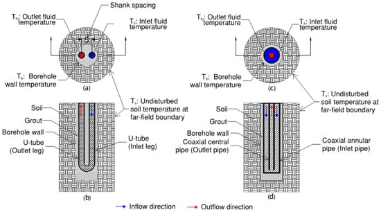
Figure 1.
Schematic diagram showing BHX; (a,b) plan and section for U-tube arrangement; (c,d) plan and section for coaxial pipe arrangement with inflow through annular pipe.
An alternative to U-tube boreholes is a coaxial pipe arrangement where a smaller pipe (the inner pipe) is enclosed within a larger outer pipe. The heat transfer fluid can be circulated in two ways. One way is to enter the fluid through the outer pipe (inlet pipe) and return the fluid via the inner pipe (outlet pipe). The other flow arrangement is to enter the fluid via the inner pipe (inlet pipe) and return the fluid via the outer pipe (outlet pipe). Figure 1c,d illustrate the coaxial pipe arrangement with inflow through the annular pipe.
Usually, the space between the U-tube/coaxial pipe and the borehole wall is filled with grout, which serves a crucial role in stabilizing the U-tube/coaxial pipe within the buried system and preventing water seepage into the borehole. The BHX cost (which is mainly the cost of U-pipe, grout, and borehole drilling) for GSHP typically accounts for more than 30% of the total cost of the GSHP system [4]. Given its significant expense, optimizing this component is vital for enhancing heat transfer efficiency and harnessing more sustainable energy from the same area of the land.
The total thermal resistance consists of two parts: the soil itself and the borehole as shown in Figure 2. In a conventional U-tube BHX with geometrical symmetry of the inlet and outlet legs, the fluid temperature to be considered for the evaluation of borehole thermal resistance is the mean temperature of the inlet and outlet fluid temperatures [5].
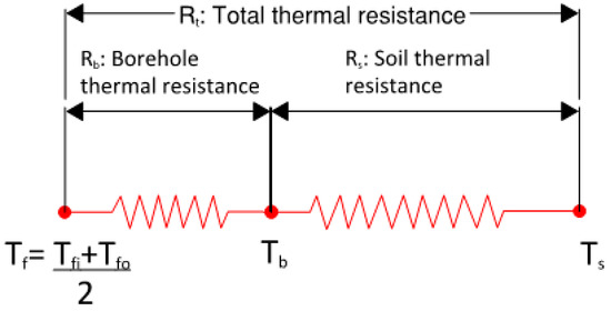
Figure 2.
Thermal resistance network for U-tube BHX.
The borehole resistance component includes the resistance offered by grout, pipe material, and the circulating fluid. Contact thermal resistance is assumed to be negligible for simplification. The total thermal resistance is the sum of soil and borehole resistance.
A reduction in any of the above two components or both will lead to improved heat transfer. The heat transfer resistance characteristics of soil vary with geographic location and are generally immutable. Deep soil mixing offers a viable method to lower soil thermal resistance, yet its implementation is expensive and may not be economically feasible across all site conditions and soil types [6]. On the other hand, there are methods to decrease Rb, i.e., BHX thermal resistance. Therefore, the overall thermal resistance of the system can be reduced for an enhanced heat transfer by adopting techniques to lower the BHX thermal resistance.
Increasing the length of the ground loop in a BHX reduces the approach of the BHX, defined as the difference between the average loop temperature Tf and the initial ground temperature Ts.
Reducing the thermal resistance between the ground and the circulating fluid enhances the heat transfer, thereby reducing the required length of the heat exchanger per kW for a given approach.
Previous research on the optimization of borehole thermal resistance has investigated the impact of pipe material, borehole diameter, shank spacing, and grout material. Research by Kerme et al. [7] discusses various geometric factors (shank spacing, borehole size/diameter, borehole depth), grout, and soil thermal conductivity for single and double U-tube arrangements, and then proposes the combined effective measures for heat transfer improvement. Shen et al. [8] discuss the various influential factors (such as flow rate, inlet temperature, heat extraction rate, length of BHX, and backfill material) on the performance of a deep U-tube BHX and suggest an optimal control of the flow rate.
According to Kavanaugh and Rafferty [2], the choice of thermally enhanced grout material is also challenging. The grout filler must block surface water and unwanted groundwater from reaching aquifers, as they can pollute drinking or irrigation supplies. High solids sodium bentonite grout (>20% solids), while effective, is a poor heat conductor, whereas materials with good heat transfer may allow water migration. Some regulations may permit porous materials if the top 6 m of the borehole are sealed with nonporous grout. Cement-based sealants are ineffective for BHXs due to pipe shrinkage but can be enhanced with additives. The pouring of thermally enhanced grout with abrasive sand might also be challenging due to the unavailability of the pumping equipment with the installer.
Erol and François [9] studied various BHE grout materials, including bentonite-based, silica sand-based, and homemade admixtures with graphite. Increasing graphite content beyond 5% or using all types of graphite powders in BHE backfill mixtures is impractical, as graphite’s varying properties can negatively affect grout flowability, permeability, and strength. Through a TRT test, they found that adding just 5% homemade natural flake graphite enhances grout thermal conductivity, crucial for optimizing heat transfer efficiency when matched appropriately to ground conductivity.
The study by Mahmoud et al. [10] suggests that selecting the right grout depends on system conditions. Traditional grouts like bentonite and cement offer strength but require additives for better thermal performance. Phase-change material (PCM) is recommended for its storage capacity and stability. A mix of conventional grouts, additives, and PCMs is recommended for optimal results.
Liu et al. [11] conducted a comprehensive study to assess potential cost reductions through enhancements in borehole heat transfer under diverse geological and thermal conditions and revealed that improvements such as enhanced grout and double U-tube loops effectively reduce borehole lengths. This study primarily focuses on installation costs and relies on the simplified geometrical approach of Eskilson’s g-function through commercial software GLHEPro.
Studies have also been conducted on the comparison of a U-tube with coaxial pipes and a few other arrangements like double U-tube, discussing the thermal behavior of the BHX with these arrangements. A study conducted by Zanchini et al. [12] showed that in coaxial pipes, the configuration where water flows into the BHX through the outer annular pipe and exits through the inner pipe provides superior thermal performance compared to the opposite arrangement, where inflow occurs through the center or inner pipe and outflow through the outer annular portion. Brown et al. [13] modeled coaxial, single U-pipe, and double U-pipe configurations, finding that coaxial pipes exhibit the highest heat transfer rate and a lower pressure drop. Harris et al. [14] demonstrated that the coaxial BHX configuration is more effective than the double U-pipe design. According to Chen et al. [15], by using double U-tubes in parallel in BHXs, the heat transfer capacity may increase by over 50% from the single U-tube system, which could justify the cost increase in installation and pumping energy consumption. Chen and Tomac [16] suggest the use of a VIT (Vacuum Insulated Tube) for coaxial pipe arrangement to prevent thermal short-circuiting. An economic analysis is suggested, as the cost of VIT could be substantially higher than the cost of uninsulated tubing.
While there is ample research available on the comparative study of the materials and geometry of the U-tube BHX and its comparison with other arrangements like coaxial pipes and double U-tube, there is not much research on segregating the inlet and outlet leg of the U-tube to prevent direct interaction with each other.
Al-Chalabi [6] investigated the effects of introducing I-shape and U-shape obstructions in a U-tube BHX. However, this study did not account for the thickness of the U-tubes, which led to extremely an overestimated efficiency of the barriers compared to scenarios where tube thickness is considered. In addition, this study is limited to the highly thermally conductive grout with a ratio kg/ks of 2 and does not provide an insight into the various alternatives of the grout and soil. The results are reported in terms of the borehole thermal resistance instead of an overall thermal resistance. High thermal conductivity grout results in a lower contribution of the BHX thermal resistance out of the total thermal resistance of the soil and BHX. Therefore, there is a need to report the net impact of the saving in terms of an overall reduction in the total thermal resistance or borehole length or an overall increase in the heat transfer.
Ngo and Ngo [17] conducted a numerical assessment to evaluate the impact of an insulated, flat shape barrier between the U-tube legs of the ground heat exchanger. This study examines the effects of the Reynolds number on heat transfer, focusing on laminar flow with a low Reynolds number value (optimal heat transfer at a Reynolds number of 120 and suggests that at lower Reynolds number values, heat transfer increases due to a decrease in the outlet temperature (Tfo) for a given inlet temperature (Tfi), though it does not address the impact of a reduced mass flow rate on the heat transfer as a result of a lower Reynolds number value. The heat rejected by the fluid for cooling will be as follows [2]:
The expression for Reynolds number is as follows [18].
The above equation depicts that the mass flow rate of the fluid is a function of the Reynolds number. Under the given geometry and fluid temperature, the Reynolds number varies directly proportional to the mass flow rate of the fluid, which means the higher the mass flow rate, the higher the Reynolds number for a given geometry and fluid temperature. In the case of turbulent flow through pipes, the Reynolds number is ≥10,000 [18]. Ngo’s study, with a Reynolds number of 120, will have a significantly lower flow rate with the same geometry compared to the flow conditions considered in other studies with a turbulent flow. This study does not very clearly state the pipe material considered; however, it mentions that their study reports high-efficiency operation with 16% enhanced heat transfer when a copper pipe is used instead of high-density polyethylene. It is therefore understood that they have conducted a study based on copper pipes. Previous studies suggest that the use of HDPE pipes is very common due to better performance, durability, and economics [2,19,20,21]. The assumption of copper piping with laminar flow within the U-tube could increase the risk of thermal short-circuiting than with a high-density polyethylene pipe [2]. Due to more short-circuiting, the results of improved heat transfer due to the barrier between the inlet and outlet pipe will be misleading. The thickness of the pipe is also neglected, which will overestimate the performance of the barrier. Because this study is not based on optimal parameters, there is a potential to increase heat transfer further by improving the flow rate and pipe material. Measures to improve these parameters will result in a change in the reported impact of the barriers in this study, which warrants further analysis to draw definitive conclusions.
Previous studies about grout material have suggested that grout selection for better thermal conductivity might be challenging and may be compromised for the strength of the BHX and/or economy. A novel technique with barriers between the two legs of a BHX to optimize heat transfer should be explored as an alternative to the conventional way of increasing the heat transfer by thermally enhanced grout. This technique can also be applied in addition to the conventional methods to further increase the heat transfer. There is a need for a detailed evaluation of the thermal performance of the barrier between the two legs of a U-tube BHX, with a specific comparison to a conventional U-tube system. Due to the complexity of the BHX geometry, a numerical assessment would be more appropriate. Flat plate and U-shape geometries of the barrier are studied with various materials and thicknesses. The design parameters of the BHX geometry and flow are optimized before evaluating the effect of the barrier. A comparison is made with a focus on depicting the sole contribution of the barrier from the base case. It is also required to report the results of the overall impact in terms of the net increase in heat transfer or the net reduction in the BHX length. This will allow for a clearer assessment of the barrier’s unique contribution in optimizing the BHX length and help implement the barrier technique, which contributes to the enhancement of heat transfer through the BHX. Additionally, it would be beneficial to compare the results of numerical assessment for barrier techniques with other heat transfer enhancement techniques, such as coaxial pipe arrangements, to offer a broader selection of borehole heat exchanger (BHX) design options.
2. Methods
A traditional single U-tube heat exchanger was numerically assessed and validated for different combinations of shank spacing and grouts. A coaxial pipe BHX was also assessed to see the improvements in efficiency of the heat transfer in the BHX with coaxial pipe arrangement compared to a traditional single U-tube BHX. Next, the effects of novel techniques with different barriers/obstructions between the two legs of a U-tube BHX were investigated and the resulting improvements were compared. Numerical assessment was performed on FlexPDE software version 6.51, a finite element model builder and solver. The undisturbed soil temperature (Ts) and fluid temperature (Tf) remained constant across all options, leading to an unchanged approach temperature, as determined by Equation (3). This study aimed to determine which borehole heat exchanger option minimized heat transfer resistance, thereby requiring the shortest length per kWt under these conditions.
2.1. Model Assumptions and Governing Equation
The analysis was performed for a single BHX under steady-state heat transfer. The heat transfer inside the borehole for longer time steps can be considered as steady-state heat transfer within that time step [22]. The lower limit of the time step is 5 times rb2/α, which is usually a few hours for different soils and borehole sizes [5,22]. Similarly, a radial steady-state approximation for the small annulus of the soil near the borehole gives an error of less than 0.3% in determining the resistance of the soil outside the borehole [22]. Thus, for a time-efficient model, we conclude that it is appropriate to consider steady-state heat transfer both inside and outside the borehole.
Homogeneous ground condition is considered in the analysis as a simplification assumption [5]. With the assumptions of steady-state heat flow and homogenous ground material, a two-dimensional model can effectively capture the essential heat flow characteristics in the material and is therefore considered for the analysis.
A far-field radius is the radius of influence, and, beyond it, the temperature of the soil remains undisturbed [23]. According to the study conducted by Ruan, the soil within 0.5 m of the borehole reacts to the short-term heat flux from the ground to the fluid. In contrast, the area beyond 0.5 m is primarily influenced by the long-term net energy input into the ground heat exchange system. After 1 m from the center of the borehole, there is no significant change in the mean fluid temperature [24]. We therefore based our analysis on a far-field radius of 1 m.
The analysis considered no contact resistance, no moisture migration through the soil, homogenous grout and pipe materials, water as a fluid, and winter heating mode.
Fourier’s law of heat conduction is as follows [25].
The transient heat transfer equation in three-dimensional cartesian coordinate system is as follows [25].
The steady-state two-dimensional equation in cartesian coordinates reduces to the following expression, which shall be the governing equation in this study and is expressed as follows [25].
2.2. Analysis of Traditional Single U-Tube Borehole Heat Exchanger
Figure 3 describes the geometry of the U-tube model within the boundaries of the soil region near the grout.
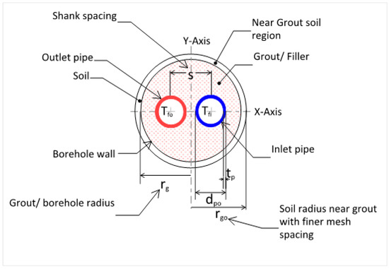
Figure 3.
U-tube BHX model geometry.
The size and material of U-tube and borehole diameter are in accordance with the recommendations in ASHRAE-Applications [3]. Heating mode for winter operation of the GSHP is considered. For better efficiency, the outlet temperature of the fluid in heating mode should be 5 °C to 8 °C less than the undisturbed ground temperature [2]. ΔT of 4 °C to 3 °C is adopted for water as a fluid to keep the cost and pumping energy within reasonable limits [2]. The soil temperature taken is an approximation used to represent a range of Australian soils, where the average geothermal ground temperatures are from 14 °C to 18 °C [26,27,28]. Soil thermal conductivity of 0.5 to 2 W/m·K also represents various soil conditions in Victoria, Australian Capital Territory, and the nearby areas of New South Whales [29,30]. The grout materials are considered to represent a variety of grouts with or without a filler material to enhance their thermal conductivity. Neat cement grout with water-to-cement ratio of 0.6 has a thermal conductivity of 0.585 W/m·K after drying, whereas grouts with thermal conductivity of 1 and 2 W/m·K represent thermally enhanced cement grouts with a combination of filler materials [31]. The description of shank spacing is shown in Figure 4 and covers the whole range of possible shank spacing from minimum to maximum in a symmetrical configuration with pipes in the center of the borehole.
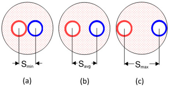
Figure 4.
Various shank spacings of U-tube BHX model.
To estimate the convective heat transfer coefficient, the flow rate of 0.642 L/s (10.2 USgpm), which is a fully developed turbulent flow under the considered geometry of the U-tube, is considered. The properties of water are taken from [32].
Reynolds number is calculated from Equation (6). Calculation of Nusselt number and convective heat transfer coefficient is from the following equations [18].
Correlation in Equation (10) is valid for forced convection in fully turbulent flow (condition met when Re ≥ 10,000 for flow in pipes) and is applicable for fluid flow in heating mode [18]. The physical and thermal properties of the numerical model along with the summary of calculated results for Re, Nu, and h are depicted in Table 1.

Table 1.
U-tube BHX model parameters.
It is to be noted that in a borehole of 100 mm with U-tube external diameter of 31.8 mm, the maximum shank spacing will be 68.2 mm; however, we have considered 68.1 mm as Smax because of the software (FlexPDE 6.51) limitations in providing solution for 68.2 mm shank spacing in a few scenarios.
Finite element triangular meshes were considered for the complete borehole field geometry. The software FlexPDE 6.51 automatically decides the initial mesh size based on the defined geometry and the complexity of the problem. For the borehole region and the soil region near the borehole, finer mesh size was defined. Region “1.1 grout” represents the soil region near the grout/borehole within a radius of rgo defined as 1.1 times rg. The soil region at the boundary of 1.1 rgo was defined with a finer mesh spacing of dpo/20. For borehole/grout, the mesh spacing was dpo/30 and that for the U-tube inlet and outlet pipes was dpo/50. With these conditions, numerical analysis on FlexPDE version 6.51 was performed.
2.3. Validation of the Results of the Numerical Model
Various analytical and semi-analytical equations available for determination of borehole thermal resistance were numerically assessed and their validity was compared to the results of numerical analysis by previous studies. Analytical models estimate the heat transfer from the borehole wall to the surrounding soil, ignoring the internal borehole region, while numerical models use finite difference or finite volume methods to calculate the temperature distribution throughout the entire domain, including both the surrounding soil and the internal borehole [36].
Sharqawy et al. [36] performed a detailed study where the effective pipe-to-borehole thermal resistance in vertical ground heat exchangers was investigated through numerical simulations. A detailed analysis was conducted to identify the dimensionless geometrical parameters that influence this thermal resistance. The heat transfer rates between U-shaped pipes and the borehole were determined numerically and compared with well-established limiting analytical solutions. A dimensionless correlation for the effective pipe-to-borehole thermal resistance was developed. The results of the empirical formula established were also compared with approximate analytical models that treat the U-shaped pipes as a single pipe with an equivalent diameter and experimental data from the literature. The findings indicated that the existing models do not provide an accurate representation of the effective pipe-to-borehole thermal resistance.
Lamarche et al. [37] also performed a detailed study on the various theoretical, empirical, and experimental approaches for determining the effective borehole thermal resistance. The multipole method (Bennett et al. 1987) was found to be the best fit for determining borehole thermal resistance.
Liao et al. [38] also proposed an empirical formula for the effective borehole thermal resistance and the dimensionless borehole thermal resistances obtained from the correlation were compared with those from other available equations.
Al-Chalabi [6] and Abuel-Naga and Al-Chalabi [39] worked on equations by Paul [40], Bennet et al. [41], Gu and O’Neal [42], Hellström [43], Shonder and Beck [44], and Sharqawy et al. [36] and found that the equation by Bennet et al. [41], i.e., Equation (12), was the closest to PDE solutions. Bennet et al. [41] utilized multipole method. This method uses a series of linear heat sources or sinks to represent the pipes within the circular borehole, allowing for the modeling of borehole configurations with multiple U-tubes, including asymmetrical setups.
λ1 = Db/Dp
λ2 = Db/s
λ3 = Dp/2s = λ2/2λ1
σ = (kg − ks)/(kg + ks)
The equation by Bennet et al. [41] does not consider the thickness of the pipe. The work by Al-Chalabi [6] and Abuel-Naga and Al-Chalabi [39] ignored thickness of U-pipe and its thermal conductivity in the numerical analysis; Bennett equation was used.
Javed and Spitler [45] studied the theoretical formulas and empirical correlations to find the effective borehole thermal resistance. It was found that the solution that is a combination of zeroth-order multipole solution and the correction originating from the first-order multipoles is the best fit for almost all scenarios. It was therefore advised to use the modified first-order multipoles method instead of other published methods.
The modified Bennett equation by Javed and Spitler [45], which accounts for pipe material, will give accurate results for this study, which accounts for the thickness of pipe material.
We therefore validated the results of FlexPDE 6.51 with the modified Bennett equation by Javed and Spitler [45]. The validation was performed for all conditions of the grout and shank spacings considered in the analysis.
where
β = 2πkg (Rp + Rf)
Rp = ln(r2/r1)/(2πkp)
Rf = 1/(2π r1 h)
β = 2πkg Rp
β = 2πkg ln(r2/r1)/(2πkp)
Table 2 shows the results of using Equation (17) compared to FlexPDE 6.51 results, where the error between the two results was only 0.5% or less. This indicates the authenticity of FlexPDE version 6.51 results and further analysis was performed using FlexPDE version 6.51.
Table 2.
Validation results for FlexPDE 6.51 analysis of U-tube BHX.
2.4. Analysis of Insulated Outlet Leg in a Conventional U-Tube Arrangement
To see the impact of insulation on the outlet leg of the U-tube BHX in reducing the thermal short-circuiting, analysis was performed for the U-tube BHX of the same parameters, as defined in Table 1, with 3 mm closed cell foam insulation on the outlet pipe. The thermal conductivity of the insulation was considered as 0.0342 W/m·K [46]. Due to insulated outlet leg, the minimum shank spacing was 34.8 mm. Analysis was performed for soil of thermal conductivity 1 W/m·K. Figure 5 schematically describes the geometry of U-tube borehole with insulated outlet leg.
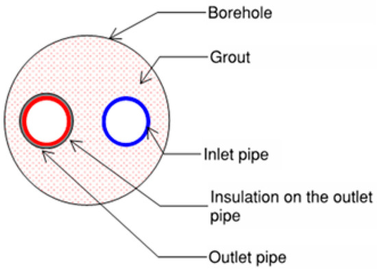
Figure 5.
U-tube BHX with insulated outlet pipe.
2.5. Analysis of Coaxial Pipe Arrangement
In the previous literature, the performance of coaxial pipe arrangement was found to be better than U-tube. Therefore, coaxial pipe arrangement was analyzed for the comparison of the improvements in the heat transfer rate. Coaxial pipes were analyzed with water flowing into the borehole through the outer annular pipe, as previous studies have shown this arrangement to be thermally more efficient than the one with inflow from the central pipe [12].
Unlike U-tube, the outlet (inner) pipe of coaxial arrangement has no direct contact with the grout and exchanges heat solely with the inlet (outer) pipe. As a result, short-circuiting effects are more evident in uninsulated coaxial pipe arrangements because of the significantly increased thermal pathway between the inlet and outlet pipes, as shown by Lamarche [5]. Due to the extremely high short-circuiting losses in uninsulated outlet pipe in coaxial arrangement, most of the previous studies recommend insulation on the outlet (inner) pipe of the coaxial arrangement of tubes to minimize the thermal short-circuiting [5,16]. For insulation of the outlet pipe, the following are few options commonly available:
- (a)
- Uniform insulation throughout the BHX, which is usually applied by insulating the outlet pipe with insulation applied on its external side. A protective pipe over the insulation is required to protect it from the water damage of the annular pipe [16,47].
- (b)
- Non-uniform insulation using vacuum insulated pipe (VIT) as the outlet pipe, where vacuum is created between two metallic pipes [16,47].
Because of two-dimensional study, we analyzed coaxial arrangement with a uniform 3 mm insulation of close cell foam on the outlet (inner) pipe under the same operating conditions. To protect the insulation from water, a PVC tube casing was considered. Because only the fluid in the outlet pipe is directly exposed to the borehole, the fluid temperature for the calculation of borehole thermal resistance is the temperature of the fluid in the outer (inlet) pipe, as shown by Lamarche [5]. Figure 6 describes the geometry of the coaxial model.
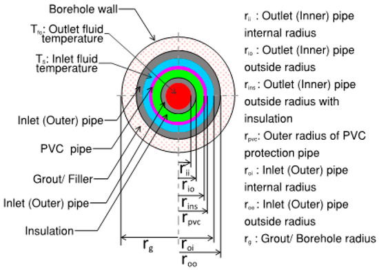
Figure 6.
Insulated coaxial pipes model geometry.
Grout and soil properties and the fluid temperatures of the model were identical to the U-tube model, as summarized in Table 1. Nusselt number was calculated from the following equations [18,48,49,50].
Correlation in Equation (23) is proposed by Gnielinski and is called Gnielinski equation. The equation is valid for 0.1 ≤ Pr ≤ 1000 and Re > 4000. According to Gnielinski [50], fann, which is the annular pipe friction factor, is different from the friction factor for the circular tube and can be calculated from the following equation.
where
For the boundary condition of heat transfer at the outer wall with inner wall insulated, fann is determined by Equation (28) [50].
Value of K is 1 if the fluid temperature at the wall of the annular pipe and the bulk fluid temperature are considered to be the same [50].
The other physical and thermal properties of the numerical model along with the summary of calculated results for Re, Nu, and h are depicted in Table 3.
Table 3.
Coaxial pipes model parameters.
The resistance network for the arrangement is shown in Figure 7. Contact thermal resistance was assumed to be negligible for simplification.
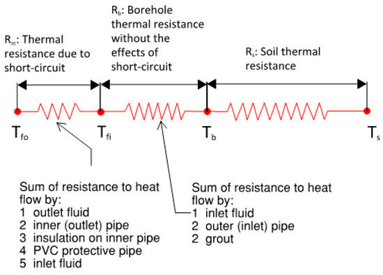
Figure 7.
Thermal resistance network for coaxial pipes BHX.
2.6. Flat Plate Barrier Arrangement Between the Inlet and Outlet Legs of the U-Tube
By introducing a flat plate barrier throughout the length of the BHX, the outlet pipe will be thermally separated from the inlet pipe, but its direct contact with the soil and grout will not be restricted. These barrier arrangements were analyzed to see if they lead to a better thermal performance. Several arrangements were analyzed numerically, which are listed as follows. Analysis was performed for soil thermal conductivity of 0.5, 1, and 2 W/m·K; grout thermal conductivity of 0.585, 1, and 2 W/m·K; and minimum, average, and maximum shank spacing. The minimum shank spacing due to insertion of the barrier will be more than the minimum shank spacing of 31.8 mm for the conventional U-pipe. If the heat transfer savings of the U-tube with barrier are compared with the conventional U-tube at a lower shank spacing of 31.8 mm, the savings will be misleading because of the comparison with a different shank spacing. Therefore, to depict the sole contribution of the barriers, the results of the analysis are compared to a conventional U-tube BHX with shank spacing Smin-actual.
Figure 8 shows these arrangements diagrammatically.
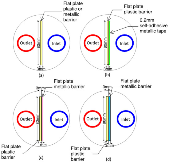
Figure 8.
Schematic of flat plate shape barrier arrangements for U-tube BHX (a) Single 3 mm flat plate plastic or metallic barrier (b) 3 mm flat plate plastic barrier with 0.2 mm metallic tape (c) Double flat plate barrier of 3 mm plastic and 1 mm metal (d) Double flat plate barrier of 3 mm plastic and 3 mm metal.
2.6.1. Analysis of Flat Plate Plastic Barrier
To minimize the thermal short-circuit losses between the inlet and outlet legs, 3 mm thick and 80 mm long plastic barriers, as shown in Figure 8a, were analyzed. The following thermal conductivities for the plastic barriers were analyzed:
- Barrier nomenclature FSB-3PL1: 3 mm flat plate shape plastic barrier of thermal conductivity 0.17 W/m·K. This may be an unplasticized polyvinyl chloride pipe (uPVC) material, which is commonly available [54].
- Barrier nomenclature FSB-3PL2: 3 mm flat plate shape plastic barrier of thermal conductivity 0.5 W/m·K. This may be a specialized rigid plastic material [55].
- Barrier nomenclature FSB-3PL3: 3 mm flat plate shape plastic barrier of thermal conductivity 2 W/m·K. This may be a specialized rigid plastic material [55].
The thickness of the barrier was considered according to previous studies and from the perspective of the strength of its underground installation [6].
2.6.2. Analysis of Flat Plate Plastic Barrier with Metallic Tape
In addition to the attempt to minimize the short-circuit losses with the plastic barrier, a 0.2 mm thermally conductive metallic tape was applied to improve the thermal distribution of the inlet pipe. Barrier nomenclature FSB-3PLMT is used for this arrangement. Metallic tapes are common in heat transfer and electronics applications. The thermal conductivity of these tapes is dependent on the thermal conductivity of the metal used, the percentage of impurities in the metal, and the thermal conductivity of the adhesive. Copper tapes usually have thermal conductivity in the range of 200–250 W/m·K and are usually available in thicknesses up to 0.2 mm [56]. Figure 8b shows the geometry. The considered tape had an overall thermal conductivity of 200 W/m·K [56].
2.6.3. Analysis of Flat Plate Metallic Barrier
To observe the sole impact of improvement in temperature distribution of inlet pipe, without an attempt to reduce the thermal short circuit between the two legs by a plastic barrier, metallic barriers were considered with a thickness of 3 mm and a width of 80 mm, as shown in Figure 8a. The following materials were considered as a barrier due to their corrosion-resistant properties, which make them suitable for underground application.
Barrier nomenclature FSB-3SS: 3 mm flat plate shape stainless steel SS304 barrier of thermal conductivity 16 W/m·K [33,57].
Barrier nomenclature FSB-3BR: 3 mm flat plate shape brass of thermal conductivity 109 W/m·K [33].
2.6.4. Analysis of Flat Plate Double Barrier
Because plastic barrier helps to mitigate short-circuiting losses and metallic barrier helps to enhance the temperature distribution of the inlet pipe, our next analysis was to see the effect of a double flat plate barrier of plastic and metal where flat plate plastic and flat plate metal barriers were combined to form a double flat barrier. The options considered for the analysis were as follows:
Barrier nomenclature FSB-3PL3AL: 4 mm double flat plate shape barrier with 3 mm plastic (thermal conductivity 0.17 W/m·K) [54] and 1 mm aluminum (thermal conductivity 237 W/m·K) [58]. Refer to Figure 8c.
Barrier nomenclature FSB-3PL3SS: 6 mm double flat plate shape barrier with 3 mm plastic thermal conductivity 0.17 W/m·K) [54] and 3 mm stainless steel (thermal conductivity 16 W/m·K) [33,57]. Refer to Figure 8d.
Barrier nomenclature FSB-3PL3BR: 6 mm double flat plate shape barrier with 3 mm plastic thermal conductivity 0.17 W/m·K) [54] and 3 mm brass (thermal conductivity 109 W/m·K) [33]. Refer to Figure 8d.
2.7. Analysis of U-Shape Barrier Arrangement Between the Inlet and Outlet Legs
For the outlet pipe, the half of the pipe facing the inlet pipe rejects heat while the other half facing the opposite side takes heat from the surrounding grout and soil. An improvement measure may be implemented by introducing a U-barrier instead of a flat plate barrier, surrounding the half perimeter of the outlet pipe from where it rejects heat and the portion of the pipe that takes heat from the ground is kept free. The barrier will surround the half perimeter of the outlet pipe and extend 10 mm further to prevent the mixing of thermal distribution of the outlet pipe and the inlet pipe.
The thermal properties of the selected materials were the same as considered in the flat plate barrier arrangements. Analysis was performed for soil thermal conductivity of 0.5, 1, and 2 W/m·K; grout thermal conductivity of 0.585, 1, and 2 W/m·K; and minimum, average, and maximum shank spacing. Like the analysis in the flat plate shape barriers, the impact of barriers in heat transfer improvement for maximum shank spacing was not found to be significant and therefore removed from further discussions. Several geometrical arrangements were analyzed numerically, which are listed as follows. Figure 9 shows these arrangements schematically.
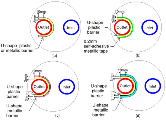
Figure 9.
Schematic of U-shape barrier arrangements for U-tube BHX (a) Single 3 mm U-shape plastic or metallic barrier (b) 3 mm U-shape plastic barrier with 0.2 mm metallic tape (c) Double U-shape barrier of 3 mm plastic and 1 mm metal (d) Double U-shape barrier of 3 mm plastic and 3 mm metal.
Barrier nomenclature USB-3PL: U-shape barrier with 3 mm thick plastic of thermal conductivity 0.17 W/m·K [54]. Refer to Figure 9a.
Barrier nomenclature USB-3PLMT: U-shape barrier with 3 mm thick plastic of thermal conductivity 0.17 W/m·K [54] and 0.2 mm self-adhesive metallic tape of an overall thermal conductivity 200 W/m·K [56]. Refer to Figure 9b.
Barrier nomenclature USB-3SS: U-shape barrier with 3 mm thick stainless steel of thermal conductivity 16 W/m·K [33,57]. Refer to Figure 9a.
Barrier nomenclature USB-3BR: U-shape barrier with 3 mm thick brass of thermal conductivity 109 W/m·K [33]. Refer to Figure 9a.
Barrier nomenclature USB-3PL1AL: 4 mm double U-shape barrier with 3 mm plastic (thermal conductivity 0.17 W/m·K [54]) and 1 mm aluminum (thermal conductivity 237 W/m·K [58]). Refer to Figure 9c.
Barrier nomenclature USB-3PL3SS: 6 mm double U-shape barrier with 3 mm plastic thermal conductivity 0.17 W/m·K [54]) and 3 mm stainless steel (thermal conductivity 16 W/m·K [33,57]). Refer to Figure 9d.
Barrier nomenclature USB-3PL3BR: 6 mm double U-shape barrier with 3 mm plastic thermal conductivity 0.17 W/m·K [54]) and 3 mm brass (thermal conductivity 109 W/m·K) [33]. Refer to Figure 9d.
3. Results
3.1. Results for U-Tube BHX
Figure 10 shows the results of the heat transfer for the inlet and outlet pipes of the U-tube with various soil, grout, and shank spacings.
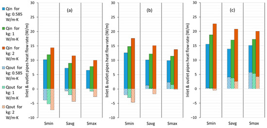
Figure 10.
Heat transfer from U-tube BHX inlet and outlet legs: (a) for ks: 0.5 W/m·K, (b) for ks: 1 W/m·K, (c) for ks: 2 W/m·K.
The results showed that the inlet pipe had a positive value for heat flux, indicating that the pipe absorbs heat from the surrounding soil. Heat transfer in the outlet occurs in two ways: a positive gain due to a 6 °C temperature difference between the soil and fluid outlet, and a negative loss due to the short-circuiting near the inlet pipe. The net heat transfer through the outlet pipe can be either positive or negative, depending on the direction in which the heat transfer is greater. The more thermally conductive the soil is, the more the net heat will be transferred. Wider shank spacing and thermally enhanced grout materials also lead to improved net heat transfer.
3.2. Results for U-Tube BHX Having Insulated Outlet Leg
As shown in Figure 11, the thermal efficiency of the insulated outlet leg of the U-tube BHX either decreased (for lower thermal conductivity grouts) or showed a marginal increase (for higher thermal conductivity grouts).
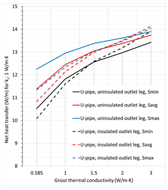
Figure 11.
Comparison of net heat transfer for uninsulated U-tube and U-tube with insulated outlet leg; ks: 1 W/m·K.
Therefore, restricting the heat flow path of the outlet leg of U-tube BHX to minimize or eliminate the thermal short-circuit losses does not always lead to better overall heat transfer efficiency. This is due to a few reasons that offset the thermal efficiency improvement by a reduction in the thermal short-circuit losses, with one being the isolation of the outlet leg from the grout and soil to exchange heat and the other being the changes in the temperature distribution of the inlet pipe due to a reduced grout area in the central region within the BHX, which leads to a decrease in the inlet pipe heat flow; at reduced shank spacings, this effect is more pronounced. In addition, the contribution of BHX thermal resistance for lower thermal conductivity grout is comparatively higher in the net heat transfer compared to the case with higher thermal conductivity grout, which makes the impact of the increase in BHX thermal resistance contribute more towards a reduction in the overall heat transfer.
3.3. Results for Coaxial Pipes
Figure 12 shows the results in terms of the heat transfer rates for inlet and outlet pipes. The thermal short-circuit losses were 2.58 W/m. These short-circuit losses remain constant for the same geometric and flow parameters, regardless of the thermal conductivity of the soil and grout; therefore, their contribution in low thermal conductivity soils and grouts is comparatively higher in the percentage of the total heat flow.

Figure 12.
Heat transfer rate from the inlet and outlet pipes for insulated coaxial pipes (inflow through outer pipe).
Figure 13 shows the net heat transfer in W/m from the inlet and outlet pipes at various operating conditions for U-tube and coaxial pipe arrangements. For the soil with comparatively lower thermal conductivity of 0.5 W/m·K, the performance of the U-pipe was better than the insulated coaxial pipe arrangement for all scenarios of the shank spacing. For soil with thermal conductivity of 1 W/m·K and grout with 0.585 W/m·K thermal conductivity, the performance of the insulated coaxial arrangement is lower for Savg and Smax and shows better performance for Smin. The same trend was observed for a grout thermal conductivity of 1 and 2 W/m·K. An increase in soil and grout thermal conductivity improved coaxial pipes’ performance better than the U-tube BHX.
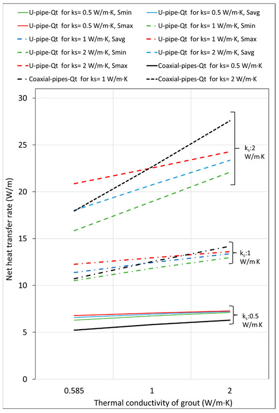
Figure 13.
Net heat transfer rate for U-tube and coaxial BHXs.
3.4. Single Flat Plate Barrier Arrangement for U-Tube BHX
3.4.1. Results for Flat Plate Plastic Barrier
Table 4 shows the results of the numerical analysis of the three arrangements of plastic flat plate barrier (FSB-3PL1, FSB-3PL2, and FSB-3PL3) at a soil thermal conductivity of 1 W/m·K. The results show that the BHX thermal resistance increased, causing a reduction instead of an increase in the total heat transfer through the borehole after introducing the thermal barrier. The plastic with a higher thermal conductivity of 0.5 W/m·K exhibited a marginally smaller negative percentage. The increase in thermal resistance or a decrease in the total heat transfer was higher for closer shank spacings and lower thermal conductivity grouts. To verify this trend, another specialized plastic material of thermal conductivity 2 W/m·K was analyzed. The results showed a marginal increase in the total heat transfer for the higher thermal conductivity plastic with the same trend of comparatively better performance at closer shank spacings and lower thermal conductivity grouts.
Table 4.
Comparison of U-tube BHX heat transfer for plastic barrier arrangements FSB-3PL1, FSB-3PL2, and FSB-3PL3; ks: 1 W/m·K.
The presence of a barrier having a thermal conductivity lower than the grout material decreased the heat transfer through the inlet pipe, resulting in a reduction in heat flow from the inlet pipe leg. Consequently, despite the mitigation of the short-circuiting losses, the net heat transfer was still lower than the base case. The plastic with a higher thermal conductivity of 2 W/m·K increased the short-circuiting effect but offered a marginal increase in the overall heat transfer.
3.4.2. Flat Plate Plastic Barrier with Self-Adhesive Metallic Tape
Table 5 shows the resulting heat transfer for barrier arrangement FSB-3PLMT, i.e., 3 mm plastic flat plate barrier with 0.2 mm self-adhesive metal tape. The table also shows the previously discussed barrier arrangement FSB-3PL1, i.e., 3 mm plastic barrier of 0.17 W/m·K for a comparison of the changes after adding a metallic layer over the plastic barrier. With lower thermal conductivity grout of 0.585 W/m·K and closest shank spacing of 35 mm, there was a significant increase in the overall heat transfer from 10.63 to 11.20 W/m, which is around a 5% increase from the base case. The percentage increase in the heat transfer rate started to diminish with increased shank spacings and thermal conductivity of the grout. With lower thermal conductivity grout of 0.585 W/m·K, the heat transfer from the outlet pipe was also improved in addition to an increase in the heat transfer through the inlet pipe. For grout materials with a higher thermal conductivity, the heat transfer in the outlet pipe decreased from the case with a simple plastic barrier without any metallic tape. However, due to the increased heat transfer in the inlet leg in the case with metallic tape on the plastic barrier, this scenario still resulted in an overall improvement in heat transfer.
Table 5.
Comparison of heat transfer for barrier arrangement FSB-3PL1 and FSB-3PLMT; ks: 1 W/m·K.
Figure 14, Figure 15 and Figure 16 show the temperature distribution within the BHX for a conventional U-tube, a U-tube with barrier arrangements FSB-3PL1 and FSB-3PLMT. The temperature distribution shown is for ks of 1 W/m·K and kg of 0.585 W/m·K. Shank spacing is 34.8 mm for Figure 14 and Figure 15, and 35 mm for Figure 16.
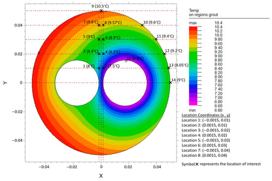
Figure 14.
Temperature distribution in grout region for conventional U-tube BHX, ks: 1 W/m·K, kg: 0.585 W/m·K, and S: 34.8 mm.
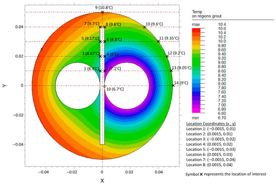
Figure 15.
Temperature distribution in grout region for U-tube BHX with barrier arrangement FSB-3PL1, ks: 1 W/m·K, kg: 0.585 W/m·K, and S: 34.8 mm.
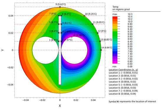
Figure 16.
Temperature distribution in grout region for U-tube BHX with barrier arrangement FSB-3PLMT, ks: 1 W/m·K, kg: 0.585 W/m·K, and S: 35 mm.
For the temperature distribution in the grout regions shown, the temperature values are also noted at a few locations, as shown in Figure 14, Figure 15 and Figure 16. In our analysis, the U-tube was centered along the x-axis; therefore, the temperatures in the upper right quarter xy plane were identical to the lower right quarter xy’ plane. Similarly, temperatures in the upper left quarter x’y plane were identical to the lower left quarter x’y’ plane.
The addition of a plastic barrier between the two legs (arrangement FSB-3PL1 and Figure 15) shows the temperature distribution for this arrangement) restricted the direct heat exchange between the inlet and outlet legs of the U-tube. Because of the restriction in the heat flow from the outlet leg, the temperature near the outlet leg at locations 1, 3, and 5 increased. Because of the restricted direct heat flow, there was no short-circuiting between the two legs, and the grout temperature near the inlet leg therefore decreased at locations 2, 4, and 6, compared to the U-tube without a barrier (Figure 14). So, the plastic barrier was positively impacting and improving the heat transfer rate in the U-tube BHX.
The resulting heat transfer rate from the outlet leg of the U-tube borehole heat exchanger improved from −0.99 W/m to 0.27 W/m. However, at the same time, the grout region near the barrier had a low thermal conductivity plastic material, which caused restricted temperature distribution from the gout to the BHX wall. The increased grout temperatures near the barrier facing the outlet leg also caused an increase in the grout temperature of the grout in the right half (xy and xy’ planes) of the BHX. As a result, the temperature near the BHX wall at locations 7, 8, and 9 and the grout regions nearby increased after the addition of a plastic barrier, and the heat flow rate from the inlet leg reduced from 11.65 W/m to 10.36 W/m. The net heat transfer rate marginally decreased from 10.67 W/m to 10.63 W/m.
The addition of metallic tape over the plastic barrier facing the inlet pipe side (arrangement FSB-3PLMT and Figure 16) decreased the overall thermal resistance between the inlet and outlet legs, causing thermal short-circuiting between the two legs due to which the overall heat flow rate from the outlet leg reduced again from 0.27 W/m (for FSB-3PL1) to 0.08 W/m (for FSB-3PLMT). Metallic tape improved the temperature distribution between the grout and BHX wall facing the inlet pipe side, causing a noticeable reduction in the temperature at locations 4, 6, and 8 to 14. This caused the heat flow rate from the inlet leg to increase from 10.36 W/m (for FSB-3PL1) to 11.12 W/m (for FSB-3PLMT). The net heat transfer rate increased from 10.63 W/m (for FSB-3PL1) to 11.2 W/m (for FSB-3PLMT).
3.4.3. Results for Flat Plate Metallic Barrier
The results of heat transfer for the two flat plate metallic barriers analyzed are shown in Table 6. The results of a conventional U-tube BHX are already shown in Table 4. Although the values of heat transfer loss from the outlet leg of the BHX are higher in these two cases than the conventional U-tube outlet leg heat loss, the overall heat transfer is improved. In addition, for closer shank spacing, the improvement in the heat transfer with barrier arrangement FSB-3SS was lower than that with barrier arrangement FSB-3PLMT, as shown in Table 5. For farther shank spacings, the performance of FSB-3SS was found to be marginally better. The heat transfer performance of the barrier arrangement FSB-3BR was significant for minimum and average shank spacings, whereas, for the farthest shank spacing of 68.1 mm, the lowest increase was noted.
Table 6.
U-tube BHX heat transfer for flat plate metallic barriers FSB-3SS and FSB-3BR, ks: 1 W/m·K.
3.4.4. Impact of Single Flat Plate Barrier on BHX Length
The analysis of single flat plate barriers in Table 4 depicted that the contribution of plastic barriers in mitigating the borehole thermal resistance is marginal or even negative in various scenarios, though adding a 0.2 mm metallic tape of thermal conductivity 200 W/m·K on 3 mm plastic barrier substantially improves the results. Therefore, plastic barriers FSB-PL1, FSB-PL2, and FSB-PL3 are not an option to increase the heat transfer of U-tube BHX.
From Table 4, Table 5 and Table 6, it was noted that the increase in heat transfer rate due to the addition of a barrier was not substantial compared to the minimum and average shank spacings; therefore, we focused on the minimum and average shank spacings only to present the resulting impact on the BHX length.
As shown in Table 7, the absolute decrease in the length of the BHX because of the barrier was higher for the lower thermal conductivity soil; however, the percentage reduction was higher for the higher thermal conductivity soil. Because the absolute reduction in length is directly related to the cost of the BHX, a comparison of absolute length reduction might lead to a better decision in terms of barrier selection.
Table 7.
Absolute and percentage reduction in length for U-tube BHX with barrier arrangement FSB-3BR.
The results of the absolute reduction in the BHX length by introducing a 3 mm plastic barrier with metallic tape (FSB-3PLMT) and 3 mm thick metallic barriers of stainless steel and brass (FSB-3SS and FSB-3BR) are shown in Figure 17 and Figure 18 for shank spacing Smin and Savg, respectively.
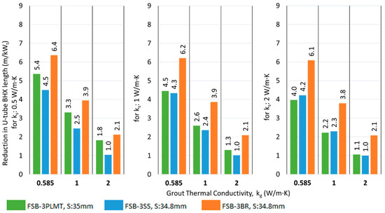
Figure 17.
Reduction in U-tube BHX length at Smin for flat plate barriers at various conditions of grout and soil thermal conductivity.
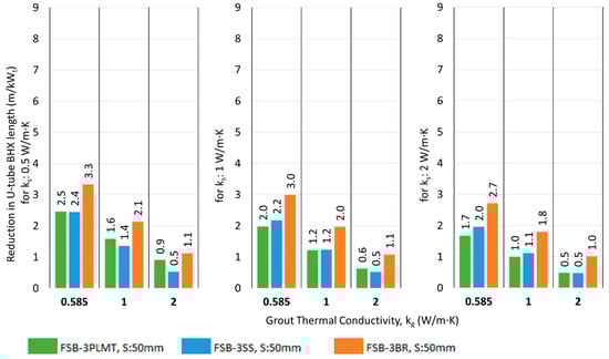
Figure 18.
Reduction in U-tube BHX length at Savg for flat plate barriers at various conditions of grout and soil thermal conductivity.
3.5. Double Flat Plate Barrier Arrangement for U-Tube BHX
3.5.1. Results for Double Barrier of 4 mm Thickness
Table 8 shows the results for the 4 mm barrier (3 mm plastic and 1 mm aluminum).
Table 8.
Comparison of heat transfer from U-tube BHX with barrier arrangement FSB-3PL1AL, ks: 1 W/m·K.
A noticeable increase in heat transfer especially with low thermal conductivity grout and closer shank spacing resulted due to the barrier.
3.5.2. Results for Double Barrier of 6 mm Thickness
Table 9 shows the results for the 6 mm barrier for two different 3 mm thick metallic barriers that are used with 3 mm PVC to form a 6 mm thick barrier. The improvement in heat transfer for a 6 mm double barrier of PVC and stainless steel was lower than observed for a 4 mm double barrier with PVC and aluminum.
Table 9.
Comparison of heat transfer from U-tube BHX with double barrier arrangements FSB-3PL3SS and FSB-3PL3BR; ks: 1 W/m·K.
3.5.3. Impact of Double Flat Plate Barrier on BHX Length
The results of the reduction in the BHX length by introducing a double flat plate barrier are shown in Figure 19 and Figure 20 for shank spacing Smin and Savg, respectively.
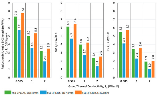
Figure 19.
Reduction in U-tube BHX length at Smin, for double flat plate barriers at various conditions of grout and soil thermal conductivity.
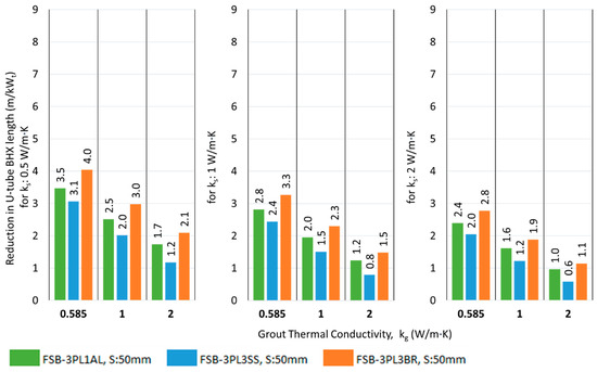
Figure 20.
Reduction in U-tube BHX length at Savg for double flat plate barriers at various conditions of grout and soil thermal conductivity.
3.6. Single U-Shape Barrier Arrangement for U-Tube BHX
3.6.1. Results for U-Shape Plastic Barrier
Table 10 depicts the results of a single U-shape barrier of PVC plastic with 0.17 W/m·K. The soil thermal conductivity was 1 W/m·K in the analysis. The results showed that the BHX thermal resistance increased, causing a reduction instead of an increase in the total heat transfer through the borehole after introducing a 3 mm thick plastic U-barrier. The trend is like the flat plate barrier case and the change in the barrier geometry from flat plate to U-shape does not help in heat transfer improvement in this case.
Table 10.
Comparison of U-tube BHX heat transfer for plastic barrier arrangements USB-3PL; ks: 1 W/m·K.
3.6.2. Results for U-Shape Plastic Barrier with Self-Adhesive Metallic Tape
Table 11 shows the resulting heat transfer and the previously discussed plastic barrier of 0.17 W/m·K for a comparison of the changes after adding a metallic layer over the plastic barrier. With lower thermal conductivity grout of 0.585 W/m·K and closest shank spacing of 35 mm, the percentage increase in the overall heat transfer from the base case was the highest. The percentage increase in the heat transfer rate started to diminish with increased shank spacings and thermal conductivity of the grout. Unlike the flat plate barrier case, with a lower thermal conductivity grout of 0.585 W/m·K, the heat transfer from the outlet pipe decreased from the base case. Also, for other grouts with higher thermal conductivity, the heat transfer in the outlet pipe was reduced compared to a plastic U-barrier with no metal tape. Due to an increase in the heat transfer of the inlet leg, overall, this arrangement improved the net heat transfer.
Table 11.
Comparison of heat transfer from U-tube BHX with barrier arrangement FSB-3PL1 and FSB-3PLMT; ks: 1 W/m·K.
3.6.3. Results for U-Shape Metallic Barrier
Table 12 shows the results of this analysis. Both metallic U-shape barrier options USB-3SS and USB3BR exhibited lower improvement in the net heat transfer than USB-3PLMT, except for one scenario. For farther shank spacings and a lower thermal conductivity grout of 0.585 W/m·K, the performance of USB-3BR was found to be marginally better.
Table 12.
U-tube BHX heat transfer for metallic U-barriers USB-3SS and USB-3BR ks: 1 W/m·K.
3.6.4. Impact of U-Shape Barrier on BHX Length
The results of the reduction in the BHX length by introducing 3 mm thick metallic barriers and a 3 mm plastic barrier with metallic tape are shown in Figure 21 and Figure 22.
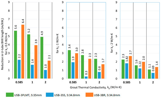
Figure 21.
Reduction in the BHX length for various single U-barriers; ks: 0.5 W/m·K.
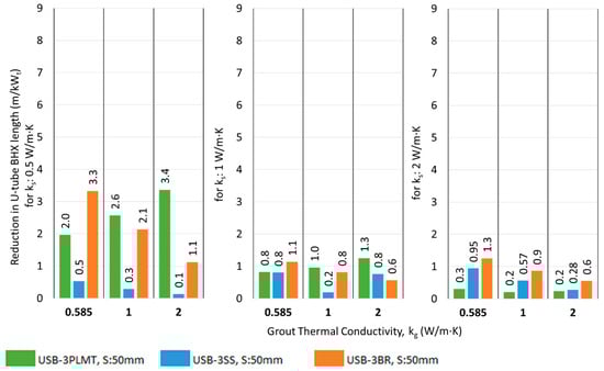
Figure 22.
Reduction in the BHX length for various single U-barriers; ks: 2 W/m·K.
3.7. Double U-Shape Barrier Arrangement for U-Tube BHX
3.7.1. Results for Double U-Shape Barrier of 4 mm Thickness
Table 13 shows the results for the barrier arrangement USB-3PL1AL, i.e., 4 mm double U-barrier (3 mm plastic and 1 mm aluminum).
Table 13.
Comparison heat transfer for U-tube BHX with double barrier arrangement USB-3PL1AL; ks: 1 W/m·K.
3.7.2. Results for Double U-Shape Barrier of 6 mm Thickness
Table 14 shows the results for the double U-barrier for two different 3 mm thick metallic barriers combined with 3 mm PVC to form a 6 mm thick barrier, which are designated as barrier arrangements USB-3PL3SS and USB-3PL3BR. The improvement in heat transfer for USB-3PL3SS was lower than observed for USB-3PL1AL.
Table 14.
U-tube BHX heat transfer for double barrier arrangements USB-3PL3SS and USB-3PL3BRks: 1 W/m·K.
3.7.3. Impact of Double U-Shape Barrier on BHX Length
The resulting reduction in the BHX length by introducing a double U-barrier with plastic and metal is shown in Figure 23 and Figure 24.
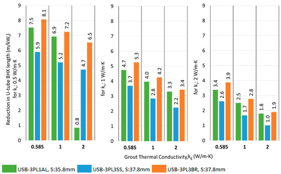
Figure 23.
Reduction in the BHX length for various U-barriers; ks: 0.5 W/m·K.
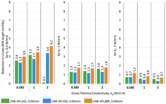
Figure 24.
Reduction in the BHX length for various U-barriers; ks: 2 W/m·K.
4. Discussion
4.1. Comparison of This Study with the Previous Studies
The barrier analysis conducted by Al-Chalabi [6] was based on a kg/ks value of 2 with a db/dp value of 3.33. The ratio db/dp in our analysis was 3.15; which is considered to be approximately equal to the value in the study by Al-Chalabi [6] for comparison. The far-field radius was 1 m in both studies. The values of the thermal conductivities of the barrier materials and their geometry were identical. The previous study mentioned the results corresponding to the ratio kg/ks, which has a value of 2 in the previous study. In this study, kg/ks value of 2 will be equivalent to the following two scenarios:
- ks of 0.5 W/m·K and kg of 1 W/m·K
- ks of 1 W/m·K and kg of 2 W/m·K
A comparative summary of the results of the analysis by Al-Chalabi [6] and the relevant results in our analysis are depicted in Table 15.
Table 15.
The comparative summary of the results of the analysis by Al-Chalabi [6] and the relevant results of this study.
The previous study presents the results in terms of the ratio kg/ks which was set as 2; however, as per this study, the results of the heat transfer rate and borehole thermal resistance for two scenarios with an identical kg/ks ratio but different values of kg and ks revealed a different value for borehole thermal resistance.
The values of borehole thermal resistance between this and the previous study do not match with the lower values in the previous study. This is because of not considering the thickness of the HDPE pipe in the analysis and therefore the resistance of the pipe material was not added to the BHX thermal resistance. In addition, it is noted in this study that increasing the soil thermal conductivity decreases the borehole thermal resistance for the same kg/ks ratio, so the difference in values in the two studies might also be due to the use of non-similar conditions of ks and kg.
In this study, the barrier technique is found to be more effective in decreasing the BHX resistance for a lower kg/ks ratio. The previous study is based on a higher value of kg/ks and therefore lacks an analysis of the scenarios where the barrier technique may perform more effectively.
The previous study discusses only the percentage reduction in the thermal resistance of the borehole and does not provide an overview of the goal of improving the heat transfer rate or reducing the BHX length. The percentage of borehole thermal resistance in the total resistance of a ground heat exchange system varies with changes in grout thermal conductivity and is higher for lower thermal conductivity grouts and gradually decreases with an increase in the grout thermal conductivity. Therefore, the indication of a percentage reduction in the thermal resistance of the borehole will not warrant the effectiveness of the barrier design, which offers a higher percentage reduction in borehole thermal resistance. Instead, the indication of the net heat transfer rate or BHX length reduction may provide a better understanding.
This study fills the gap in the previous study by providing a comprehensive study discussing various combinations of soil and grout thermal conductivity with a conclusive indication of heat transfer rates and BHX length reduction.
4.2. Comparision of Different Barriers with Conventional U-Tube
The impact of a barrier between the U-tube legs of a BHX in reducing the length is better for closer shank spacing than average shank spacing. For example, the saving in U-tube BHX length decreases from 6.4 to 3.3 m/kWt in the case of FSB-3BR with ks of 0.5 W/m·K and kg of 0.585 W/m·K when the shank spacing increases from 34.8 mm to 50 mm (refer to Figure 17 and Figure 18). For average shank spacing of 50 mm, the maximum reduction in the absolute length of the BHX due to barrier arrangement was 4 m/kWt for the flat plate barrier when the FSB-3PL3BR double flat plate barrier was introduced for Savg, ks of 0.5 W/m·K and kg of 0.585 W/m·K. For the U-shape barrier, the maximum reduction was 4.2 W/m·K when the USB-3PL3BR double flat plate barrier was introduced for Savg, ks of 0.5 W/m·K and kg of 2 W/m·K.
The absolute reduction in length was found to be higher for lower thermal conductivity grout, except for the case of double U-barriers with average shank spacing, where the absolute reduction for higher thermal conductivity grout was found to be higher.
The performance of flat plate-shaped barriers did not show a significant variation across different soil thermal conductivities when the grout thermal conductivity remained constant. However, this difference becomes quite pronounced for U-shaped barriers. For example, the reduction in BHX length for the case of FSB-3BR at Smin and kg of 0.585 W/m·K is 6.4, 6.2, and 6.1 m/kWt for a soil thermal conductivity of 0.5, 1, and 2 W/m·K, respectively; whereas, for the case of USB-3BR at Smin and kg of 0.585 W/m·K, the reduction was 6.4, 3.0, and 2.7 m/kWt for a soil thermal conductivity of 0.5, 1, and 2 W/m·K, respectively.
The performance of the double U-barrier USB-3PL3BR was found to be the best out of various single and double U-shaped barriers. The same trend was noted for flat shape barriers, where FSB-3PL3BR was also the best in thermal performance.
The performance of flat plate barrier arrangement FSB-3PLMT was found to be better than FSB-3SS for almost all scenarios of shank spacing, ks,, and kg; the same trend was observed for the U-shape barrier, where USB-3PLMT also outperformed USB-3SS.
The absolute reduction in length achieved by using a double flat plate barrier was not twice that of the single metallic barrier under the same operating conditions but instead showed a slight increase. For instance, with ks of 0.5 W/m·K and kg of 0.585 W/m·K, the BHX length reduction was improved from 6.4 m/kWt to 7.8 m/kWt, representing a further reduction of 1.4 m/kWt (or 22%) between the FSB-3BR and FSB-3PL3BR. This trend was even less pronounced at higher soil thermal conductivities of 1 and 2 W/m·K. For U-shaped barriers, the trend showed a marginal improvement over flat plate barriers.
4.3. Overall Comparison of Different Ground Heat Exchange Systems Discussed in This Study
The design of the insulated outlet leg of the U-tube BHX was found to be ineffective in improving the heat transfer rate of the BHX. The design of the coaxial pipe arrangement showed that the arrangement was suitable for improving the heat transfer for medium and high thermal conductivity soil of 1 and 2 W/m·K. For soil with a low thermal conductivity of 0.5 W/m·K, the significant short-circuit losses in coaxial pipes make the conventional U-tube a more favorable option compared to coaxial pipes.
Figure 25, Figure 26 and Figure 27 show the absolute reduction in the BHX length compared to the coaxial pipe arrangement for ks of 0.5, 1, and 2 W/m·K, respectively. The figures show the length reduction for the conventional U-tube BHX and different scenarios of the U-tube BHX with single and double barriers. The performance of the stainless steel barrier options (FSB-3SS and USB-3SS) was found to be comparable to or lower than that of the FSB-3PLMT and USB-3PLMT options in most scenarios. As a result, for simplicity, the single stainless steel barrier options were omitted from these figures. Similarly, the performance of FSB-3PL3SS and USB-3PL3SS were found to be worse than FSB-3PL1AL and USB-3PL1AL and therefore omitted.
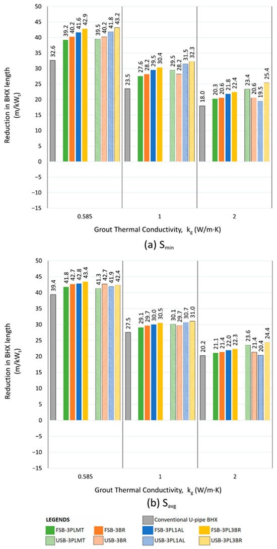
Figure 25.
Reduction in length for various arrangements of U-tube BHX compared to coaxial pipes; ks: 0.5 W/m·K, (a) Smin, (b) Savg.
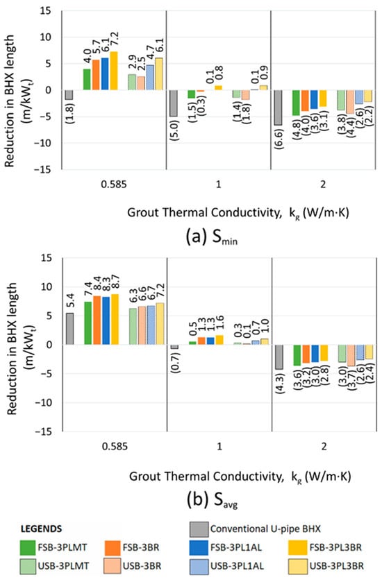
Figure 26.
Reduction in length for various arrangements of U-tube BHX compared to coaxial pipes; ks: 1 W/m·K, (a) Smin, (b) Savg.
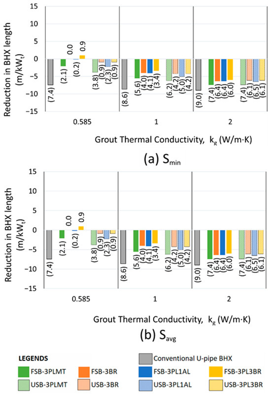
Figure 27.
Reduction in length for various arrangements of U-tube BHX compared to coaxial pipes; ks: 2 W/m·K, (a) Smin, (b) Savg.
The minimum shank spacing (Smin) for the various U-tube BHX configurations shown in Figure 25, Figure 26 and Figure 27 varies depending on the geometry. It is 31.8 mm for the conventional U-tube BHX, 34.8 mm for FSB-3BR and USB-3BR, 35 mm for FSB-3PLMT and USB-3PLMT, 35.8 mm for FSB-3PL1AL and USB-3PL1AL, and 37.8 mm for FSB-3PL3BR and USB-3PL3BR. The average shank spacing is 50 mm across all options.
In Figure 25, Figure 26 and Figure 27, for the configurations where the performance of the conventional U-tube BHX (without a barrier) is superior to the coaxial pipe arrangement, the contribution of the barrier to reducing the BHX length is the difference in length reduction between the conventional U-tube and the barrier-equipped option. For example, in Figure 25, with ks and kg values of 0.5 and 0.585 W/m·K at Savg, replacing coaxial pipes with a conventional U-tube BHX reduces the length from 191.4 m/kWt (for coaxial pipes) to 158.8 m/kWt (for the conventional U-tube). Adding the USB-3PL3BR barrier to the U-tube BHX further reduces the length to 148.2 m/kWt.
The best-performing barriers were the double barriers made of 3 mm plastic and 3 mm brass, both in flat plate and U-shape configurations. The flat plate barrier FSB-3PL3BR outperformed the U-shape barrier USB-3PL3BR in reducing the BHX length for a kg value of 0.585 W/m·K. However, the USB-3PL3BR demonstrated better performance than the FSB-3PL3BR for a kg value of 2 W/m·K, as shown in Figure 25, Figure 26 and Figure 27. The performance difference between FSB-3PL3BR and USB-3PL3BR was minimal for a kg value of 1 W/m·K.
Based on Figure 25, Figure 26 and Figure 27, we created the decision tree, as shown in Figure 28, for the selection of the best ground heat exchange system to obtain an optimized length of the BHX. Soil with 0.5, 1, and 2 W/m·K is considered as low, medium, and high thermal conductivity soil, respectively. Grout thermal conductivity of 0.585, 1, and 2 W/m·K is considered low, medium, and high, respectively.
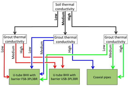
Figure 28.
Decision tree for the type of BHX with the minimum length.
5. Conclusions
Vertical ground source heat pumps can be implemented as an economical option for heating/cooling, subject to them being carefully designed, especially for ground loop heat exchangers. Over-designing this component will lead to an uneconomical design, whereas under-designing will lead to discomfort. There is a need to adopt techniques to reduce borehole thermal resistance or, in other words, to improve the heat transfer process across the BHX.
Various barrier arrangements between the two legs of the U-tube BHX have been proposed, which provide a viable alternative to conventional U-tube arrangements and serve as a better option than coaxial pipes in certain conditions of soil and grout thermal conductivity.
The double barrier arrangement, FSB-3PL3BR and USB-3PL3BR, has shown the best performance compared to a conventional U-tube BHX, with a possible reduction of 7.8 and 8.1 m in the length of the BHX per kW of heat transfer, respectively, for ks of 0.5 W/m·K and kg of 0.585 W/m·K. The other simple option of a 3 mm plastic barrier with 0.2 mm metallic tape, i.e., barrier arrangements FSB-3PLMT and USB-3PLMT, though offering comparatively lower heat transfer improvements, may still perform economically, especially in settings where installation simplicity and cost-effectiveness are prioritized. A reduction of 7.3 and 7.5 m in the length of the BHX per kW of heat transfer is possible from FSB-3PLMT and USB-3PLMT for ks of 0.5 W/m·K and kg of 0.585 W/m·K.
This study demonstrates that the novel design of barriers with various geometries and materials between the two legs of a U-tube BHX presents viable alternatives to conventional U-tube arrangements in ground heat exchanger systems and shows better performance over coaxial pipes for low to medium thermal conductivity soil and grout. Although flat and U-shape barriers with 3 mm plastic and 3 mm brass were the best options for length reduction, the other options discussed in this study, which showed an improvement in the heat transfer, may also be considered based on simplicity in construction or lower cost. A cost–benefit analysis is recommended for the selection of the type of BHX arrangement among the various options discussed for a given soil condition, especially where the difference between various options is marginal.
The barrier techniques in this study are limited to two-dimensional steady-state analysis. Further numerical study with a three-dimensional analysis may precisely determine the resulting reduction in the BHX length. Dynamic modeling may also help in the precise determination of the overall improvement in heat transfer for the long term. A minimum overall barrier thickness of 3 mm has been considered to ensure the strength and stability of the barrier for deep burial in the vertical borehole. Structure analysis of the precise thickness of the barrier may be undertaken for further optimization. This study can be continued for double U-pipe arrangements and other configurations.
Author Contributions
Conceptualization, A.N. and H.A.-N.; methodology, A.N. and H.A.-N.; software, A.N.; validation, A.N.; formal analysis, A.N.; investigation, A.N.; resources, A.N. and H.A.-N.; data curation, A.N.; writing—original draft preparation, A.N.; writing—review and editing, A.N.; visualization, A.N.; supervision, H.A.-N.; project administration, H.A.-N. All authors have read and agreed to the published version of the manuscript.
Funding
This research work was conducted as a part of Asfia Nishat’s Master by Research program supervised by Hossam Abuel-Naga, at Latrobe University, Melbourne, Australia. This research received no external funding.
Data Availability Statement
The data presented in this study are openly available in the article.
Acknowledgments
The authors wish to thank anonymous reviewers for their valuable feedback and constructive comments, which significantly contributed to improving the quality of this work.
Conflicts of Interest
The authors declare no conflict of interest.
Nomenclature
| Nomenclature for the Barrier Arrangements Discussed | |
| FSB-3PL1 | Flat plate shape barrier—3 mm plastic of thermal conductivity 0.17 W/m·K |
| FSB-3PL2 | Flat plate shape barrier—3 mm plastic of thermal conductivity 0.5 W/m·K |
| FSB-3PL3 | Flat plate shape barrier—3 mm plastic of thermal conductivity 2 W/m·K |
| FSB-3PLMT | Flat plate shape barrier—3 mm plastic of thermal conductivity 0.17 W/m·K and 0.2 mm metal tape of thermal conductivity 200 W/m·K |
| FSB-3SS | Flat plate shape barrier—3mm stainless steel of thermal conductivity 16 W/m·K |
| FSB-3BR | Flat plate shape barrier—3 mm brass of thermal conductivity 109 W/m·K |
| FSB-3PL1AL | Double flat plate shape barrier—3 mm plastic of thermal conductivity 0.17 W/m·K and 1 mm aluminum of thermal conductivity 237 W/m·K |
| FSB-3PL3SS | Double flat plate shape barrier—3 mm plastic of thermal conductivity 0.17 W/m·K and 3 mm stainless steel of thermal conductivity 16 W/m·K |
| FSB-3PL3BR | Double flat plate shape barrier—3 mm plastic of thermal conductivity 0.17 W/m·K and 3 mm brass of thermal conductivity 109 W/m·K |
| USB-3PL | U-shape barrier—3 mm plastic of thermal conductivity 0.17 W/m·K |
| USB-3PLMT | U-shape barrier—3 mm plastic of thermal conductivity 0.17 W/m·K and 0.2 mm metal tape of thermal conductivity 200 W/m·K |
| USB-3SS | U-shape barrier—3 mm stainless steel of thermal conductivity 16 W/m·K |
| USB-3BR | U-shape barrier—3 mm brass of thermal conductivity 109 W/m·K |
| USB-3PL1AL | Double U-shape barrier—3 mm plastic of thermal conductivity 0.17 W/m·K and 1 mm aluminum of thermal conductivity 237 W/m·K |
| USB-3PL3SS | Double U-shape barrier—3 mm plastic of thermal conductivity 0.17 W/m·K and 3 mm stainless steel of thermal conductivity 16 W/m·K |
| USB-3PL3BR | Double U-shape barrier—3 mm plastic of thermal conductivity 0.17 W/m·K and 3 mm brass of thermal conductivity 109 W/m·K |
| Other Nomenclature | |
| Ac | Area of cross-section in m2 |
| BHX | Borehole heat exchanger |
| BHXs | Borehole heat exchangers |
| Cp | Specific heat at constant pressure in kJ/kg·K |
| ΔT | Temperature difference |
| Db | Borehole diameter in mm or m |
| Dh | Hydraulic diameter in mm or m |
| Dp | Pipe external diameter in mm or m |
| h | Convective heat transfer coefficient of the fluid in W/m2·K |
| kg | Grout thermal conductivity in W/m·K |
| kp | Pipe thermal conductivity in W/m·K |
| ks | Soil thermal conductivity in W/m·K |
| kWt | kilo-watt thermal |
| L | Length of U-tube pipe |
| mf | Mass flow rate of fluid |
| Nu | Nusselt number |
| Pr | Prandtl number |
| Q or q | Heat flow rate in W/m |
| Qin | Heat transfer rate in the inlet pipe in W/m |
| Qout | Heat transfer rate in the outlet pipe in W/m |
| qgen | Heat generated in W |
| r1 | Pipe internal radius in mm or m |
| rb | Borehole radius in mm or m |
| Re | Reynolds number |
| Rb | Thermal resistance of borehole in (W/m·K)−1 |
| Rfo | Thermal resistance of fluid in the inside pipe for coaxial pipes in (W/m·K)−1 |
| Rfo | Thermal resistance of fluid in the outside pipe for coaxial pipes in (W/m·K)−1 |
| Rg | Thermal resistance of grout in (W/m·K)−1 |
| Rins | Thermal resistance of insulation for coaxial pipes in (W/m·K)−1 |
| Rp | Thermal resistance of pipe for U-tube BHX in (W/m·K)−1 |
| Rpi | Thermal resistance of inside pipe for coaxial pipes in (W/m·K)−1 |
| Rpo | Thermal resistance of outside pipe for coaxial pipes in (W/m·K)−1 |
| Rpvc | Thermal resistance of PVC protective pipe for coaxial pipes in (W/m·K)−1 |
| Rs | Thermal resistance of soil in (W/m·K)−1 |
| Rsc | Thermal resistance due to short circuit between inlet and outlet pipes in (W/m·K)−1 |
| Rt | Total thermal resistance of BHX in (W/m·K)−1 |
| S or s | Shank spacing in mm or m |
| Smax | Maximum Shank spacing in mm or m |
| Savg | Average Shank spacing in mm or m |
| Smin | Minimum Shank spacing in mm or m |
| Ts | Undisturbed soil temperature at far-field boundary in °C |
| Tbhw | Temperature of borehole wall in °C |
| Tf | Average fluid temperature of inlet and outlet pipe of U-tube heat exchanger in °C |
| Tfi | Average fluid temperature of inlet pipe of U-tube heat exchanger in °C |
| Tfo | Average fluid temperature of outlet pipe of U-tube heat exchanger in °C |
| Vavg | Average velocity of fluid in m/s |
| α | Thermal diffusivity in m2/s |
| ρ | Density in kg/m3 |
| τ | Time |
| γ | Euler’s constant = 0.5772 |
Abbreviations
| ASHRAE | American Society of Heating, Refrigeration and Air-conditioning Engineers |
| GSHP | Ground source heat pump |
| HDPE | High-density polyethylene |
| PDE | Partial differential equation |
| PE | Polyethylene |
| TRT | Thermal response test |
| PVC | Polyvinyl chloride |
| uPVC | Unplasticized polyvinyl chloride |
References
- Sarbu, I.; Sebarchievici, C. Using Ground-Source Heat Pump Systems for Heating/Cooling of Buildings. In Advances in Geothermal Energy; Ismail, B.I.A., Ed.; IntechOpen: Rijeka, UK, 2016; p. 17. [Google Scholar]
- Kavanaugh, S.; Rafferty, K. Geothermal Heating and Cooling, Design of Ground Source Heat Pump Systems; ASHRAE: Atlanta, GA, USA, 2014. [Google Scholar]
- ASHRAE. Handbook: HVAC Applications, SI ed.; ASHRAE: Peachtree Corners, GA, USA, 2023. [Google Scholar]
- Yoon, S.; Lee, S.; Go, G. A numerical and experimental approach to the estimation of borehole thermal resistance in ground heat exchangers. Energy 2014, 71, 547–555. [Google Scholar] [CrossRef]
- Lamarche, L. Fundamentals of Geothermal Heat Pump Systems, Design and Application, 1st ed.; Springer: Cham, Switzerland, 2023. [Google Scholar]
- Al-Chalabi, R. Thermal Resistance of U-tube Borehole Heat Exchanger System: Numerical Study. Master’s Thesis, University of Manchester, Manchester, UK, 2013. [Google Scholar]
- Kerme, E.D.; Fung, A.S.; Leong, W.H. Analysis of the Combined Effect of Major Influencing Parameters for Designing High-Performance Single (sBHE) and Double (dBHE) U-Tube Borehole Heat Exchangers. Energies 2024, 17, 2525. [Google Scholar] [CrossRef]
- Shen, J.; Zhou, C.; Luo, Y.; Tian, Z.; Zhang, S.; Fan, J.; Ling, Z. Comprehensive thermal performance analysis and optimization study on U-type deep borehole ground source heat pump systems based on a new analytical model. Energy 2023, 274, 127367. [Google Scholar] [CrossRef]
- Erol, S.; François, B. Efficiency of various grouting materials for borehole heat exchangers. Appl. Therm. Eng. 2014, 70, 788–799. [Google Scholar] [CrossRef]
- Mahmoud, M.; Ramadan, M.; Pullen, K.; Abdelkareem, M.A.; Wilberforce, T.; Olabi, A.G.; Naher, S. A review of grout materials in geothermal energy applications. Int. J. Thermofluids 2021, 10, 100070. [Google Scholar] [CrossRef]
- Liu, X.; Polsky, Y.; Qian, D.; Mcdonald, J. An Analysis on Cost Reduction Potential of Vertical Bore Ground Heat Exchangers Used for Ground Source Heat Pump Systems. In Proceedings of the Stanford Geothermal Workshop 44th Annual Conference, Stanford, CA, USA, 11–13 February 2019. [Google Scholar]
- Zanchini, E.; Lazzari, S.; Priarone, A. Effects of flow direction and thermal short-circuiting on the performance of coaxial ground heat exchangers. In Proceedings of the International Conference on Renewable Energies and Power Quality (ICREPQ’09) 2009, Valencia, Spain, 15–17 April 2009. [Google Scholar]
- Brown, C.S.; Kolo, I.; Banks, D.; Falcone, G. Comparison of the thermal and hydraulic performance of single U-tube, double U-tube and coaxial medium-to-deep borehole heat exchangers. Geothermics 2024, 117, 102888. [Google Scholar] [CrossRef]
- Harris, B.E.; Lightstone, M.F.; Reitsma, S.; Cotton, J.S. Analysis of the transient performance of coaxial and u-tube borehole heat exchangers. Geothermics 2022, 101, 102319. [Google Scholar] [CrossRef]
- Chen, J.; Qiao, W.; Xue, Q.; Zheng, H.; An, E. Research on ground-coupled heat exchangers. Int. J. Low-Carbon Technol. 2010, 5, 35–41. [Google Scholar] [CrossRef]
- Chen, H.; Tomac, I. Technical review on coaxial deep borehole heat exchanger. Geomech. Geophys. Geo-Energy Geo-Resour. 2023, 9, 120. [Google Scholar] [CrossRef]
- Ngo, I.L.; Ngo, V.H. A new design of ground heat exchanger with insulation plate for effectively geothermal management. Geothermics 2022, 105, 102512. [Google Scholar] [CrossRef]
- ASHRAE. Handbook: HVAC Fundamentals, SI ed.; ASHRAE: Peachtree Corners, GA, USA, 2021. [Google Scholar]
- Javadi, H.; Ajarostaghi, S.S.M.; Rosen, M.A.; Pourfallah, M. Performance of ground heat exchangers: A comprehensive review of recent advances. Energy 2019, 178, 207–233. [Google Scholar] [CrossRef]
- Magdic, L.; Zakula, T.; Boban, L. Improved Analysis of Borehole Heat Exchanger Performance. Energies 2023, 16, 6116. [Google Scholar] [CrossRef]
- Mendrinos, D.; Katsantonis, S.; Karytsas, C. Pipe materials for borehole heat exchangers. In Proceedings of the European Geothermal Congress, Strasbourg, France, 19–24 September 2016. [Google Scholar]
- Eskilson, P. Thermal Analysis of Heat Extraction Boreholes; Department of Mathematical Physics, University of Lund: Lund, Sweden, 1987. [Google Scholar]
- Ruan, W.; Horton, W.T. Model-Based Performance Analysis of a Single Borehole in Ground Heat Exchanger. In Proceedings of the International High Performance Buildings Conference, Purdue, Italy, 12–15 July 2010. [Google Scholar]
- Zhou, K.; Mao, J.; Li, Y.; Zhang, H.; Deng, Z. Prediction and parametric analysis of 3D borehole and total internal thermal resistance of single U-tube borehole heat exchanger for ground source heat pumps. Energy Built Environ. 2023, 4, 179–194. [Google Scholar] [CrossRef]
- Naterer, G.F. Advanced Heat Transfer; Taylor & Francis Group: Milton, UK, 2021. [Google Scholar]
- Faizal, M.; Bouazza, A.; Singh, R.M. Heat transfer enhancement of geothermal energy piles. Renew. Sustain. Energy Rev. 2016, 57, 16–33. [Google Scholar] [CrossRef]
- Sadeghi, H.; Singh, R.M. Driven precast concrete geothermal energy piles: Current state of knowledge. Build. Environ. 2023, 228, 109790. [Google Scholar] [CrossRef]
- Are Geothermal Heat Pumps for Me. Toyesi. 2024. Available online: https://toyesi.com.au/ (accessed on 19 October 2024).
- Barry-Macaulay, D.; Bouazza, A.; Singh, R.M.; Wang, B.; Ranjith, P.G. Thermal conductivity of soils and rocks from the Melbourne (Australia) region. Eng. Geol. 2013, 164, 131–138. [Google Scholar] [CrossRef]
- Usowicz, B.; Łukowski, M.I.; Rüdiger, C.; Walker, J.P.; Marczewski, W. Thermal properties of soil in the Murrumbidgee River Catchment (Australia). Int. J. Heat Mass Transf. 2017, 115, 604–614. [Google Scholar] [CrossRef]
- Allan, M.L.; Kavanaugh, S.P. Thermal Conductivity of Cementitious Grouts and Impact On Heat Exchanger Length Design for Ground Source Heat Pumps. HVACR Res. 2011, 5, 85–96. [Google Scholar] [CrossRef]
- Holman, J.P. Heat Transfer, 10th ed.; McGraw Hill: New York, NY, USA, 2010. [Google Scholar]
- Thermal Conductivity of Common Materials and Gases. n.d. Available online: https://www.engineeringtoolbox.com (accessed on 9 February 2025).
- Olam, M. Mechanical and Thermal Properties of HDPE/PET Microplastics, Applications, and Impact on Environment and Life. In Advances and Challenges in Microplastics; IntechOpen: London, UK, 2023. [Google Scholar]
- HDPE Pipe Systems: Product Catalogue. Acu-Tech Piping Systems. Available online: https://www.acu-tech.com.au/catalogues/ (accessed on 2 October 2024).
- Sharqawy, M.H.; Mokheimer, E.M.; Badr, H.M. Effective pipe-to-borehole thermal resistance for vertical ground heat exchangers. Geothermics 2009, 38, 271–277. [Google Scholar] [CrossRef]
- Lamarche, L.; Kajl, S.; Beauchamp, B. A review of methods to evaluate borehole thermal resistances in geothermal heat-pump systems. Geothermics 2010, 39, 187–200. [Google Scholar] [CrossRef]
- Liao, Q.; Zhou, C.; Cui, W.; Jen, T.C. Effective Borehole Thermal Resistance of A Single U-Tube Ground Heat Exchanger. Numer. Heat Transf. Part A Appl. 2012, 62, 197–210. [Google Scholar] [CrossRef]
- Abuel-Naga, H.; Al-Chalabi, R. Borehole thermal resistance of U-tube borehole heat exchanger. Géotechnique Lett. 2016, 6, 250–255. [Google Scholar] [CrossRef]
- Paul, N.D. The Effect of Grout Thermal Conductivity on Vertical Geothermal Heat Exchanger Design and Performance; South Dakota University: Vermillion, SD, USA, 1996. [Google Scholar]
- Bennet, J.; Claesson, J.; Hellström, G. Multipole Method to Compute the Conductive Heat Transfer to and Between Pipes in a Composite Cylinder. Notes on Heat Transfer 3-1987; Department of Building Physics, Lund Institute of Technology: Lund, Sweden, 1987. [Google Scholar]
- Gu, Y.; O’Neal, D.L. Development of an equivalent diameter expression for vertical U-tubes used in ground-coupled heat pumps. ASHRAE Trans. 1998, 104, 347. [Google Scholar]
- Hellström, G. Ground heat storage, thermal analyses of duct storage systems, part I: Theory. In Mathematical Physics; University of Lund: Lund, Sweden, 1991. [Google Scholar]
- Shonder, J.A.; Beck, J.V. Field test of a new method for determining soil formation thermal conductivity and borehole resistance/Discussion. ASHRAE Trans. 2000, 106, 843. [Google Scholar]
- Javed, S.; Spitler, J.D. Calculation of borehole thermal resistance. In Advances in Ground-Source Heat Pump Systems; Rees, S., Ed.; Elsevier Science & Technology: Amsterdam, The Netherlands, 2016. [Google Scholar]
- EPDM Sheet and Roll insulation Data Sheet 062424. Aeroflex. 2024. Available online: http://www.aeroflexusa.com (accessed on 1 August 2024).
- Luo, Y.; Xu, G.; Yan, T. Performance evaluation and optimization design of deep ground source heat pump with non-uniform internal insulation based on analytical solutions. Energy Build. 2020, 229, 110495. [Google Scholar] [CrossRef]
- Yavuzturk, C. Modelling of Vertical Ground Loop Heat Exchangers for Ground Source Heat Pump Systems; Faculty of the Graduate College, Oklahoma State University: Stillwater, OK, USA, 1999. [Google Scholar]
- Pan, A.; Lu, L.; Cui, P.; Jia, L. A new analytical heat transfer model for deep borehole heat exchangers with coaxial tubes. Int. J. Heat Mass Transf. 2019, 141, 1056–1065. [Google Scholar] [CrossRef]
- Gnielinski, V. Turbulent Heat Transfer in Annular Spaces—A New Comprehensive Correlation. Heat Transf. Eng. 2015, 36, 787–789. [Google Scholar] [CrossRef]
- Steel, A. Pipe Dimensions Chart Rev Jan 2012. Available online: https://www.scribd.com/doc/231925096/Pipe-Dimensions-Chart-Rev-Jan-2012 (accessed on 3 February 2025).
- ANSI Schedule 40 Steel Pipes—Dimensions: The Engineering ToolBox. Available online: https://www.engineeringtoolbox.com/ansi-steel-pipes-d_305.html (accessed on 25 December 2024).
- Iplex PVC U Pressure Series-1 Pipe-Dimensions. n.d. Available online: www.iplex.com.au (accessed on 22 December 2024).
- Professional Plastics Thermal Properties of Plastic Materials n.d. Available online: https://www.professionalplastics.com (accessed on 25 December 2024).
- Acierno, D.; Patti, A. Thermal Conductivity of Polypropylene-Based Materials. In Polypropylene—Polymerization and Characterization of Mechanical and Thermal Properties; Wang, W., Zeng, Y., Eds.; IntechOpen: Rijeka, UK, 2019. [Google Scholar]
- 3M(TM) Thermally Conductive Heat Spreading Tape 9876. Available online: www.3M.com/electronics (accessed on 25 December 2024).
- Stainless Steel 304—1.4301 Data Sheet: Thyssenkrupp Materials (UK). Available online: https://www.thyssenkrupp-materials.co.uk/stainless-steel-304-14301.html (accessed on 7 August 2024).
- Zhang, A.; Li, Y. Thermal Conductivity of Aluminum Alloys—A Review. Materials 2023, 16, 2972. [Google Scholar] [CrossRef]
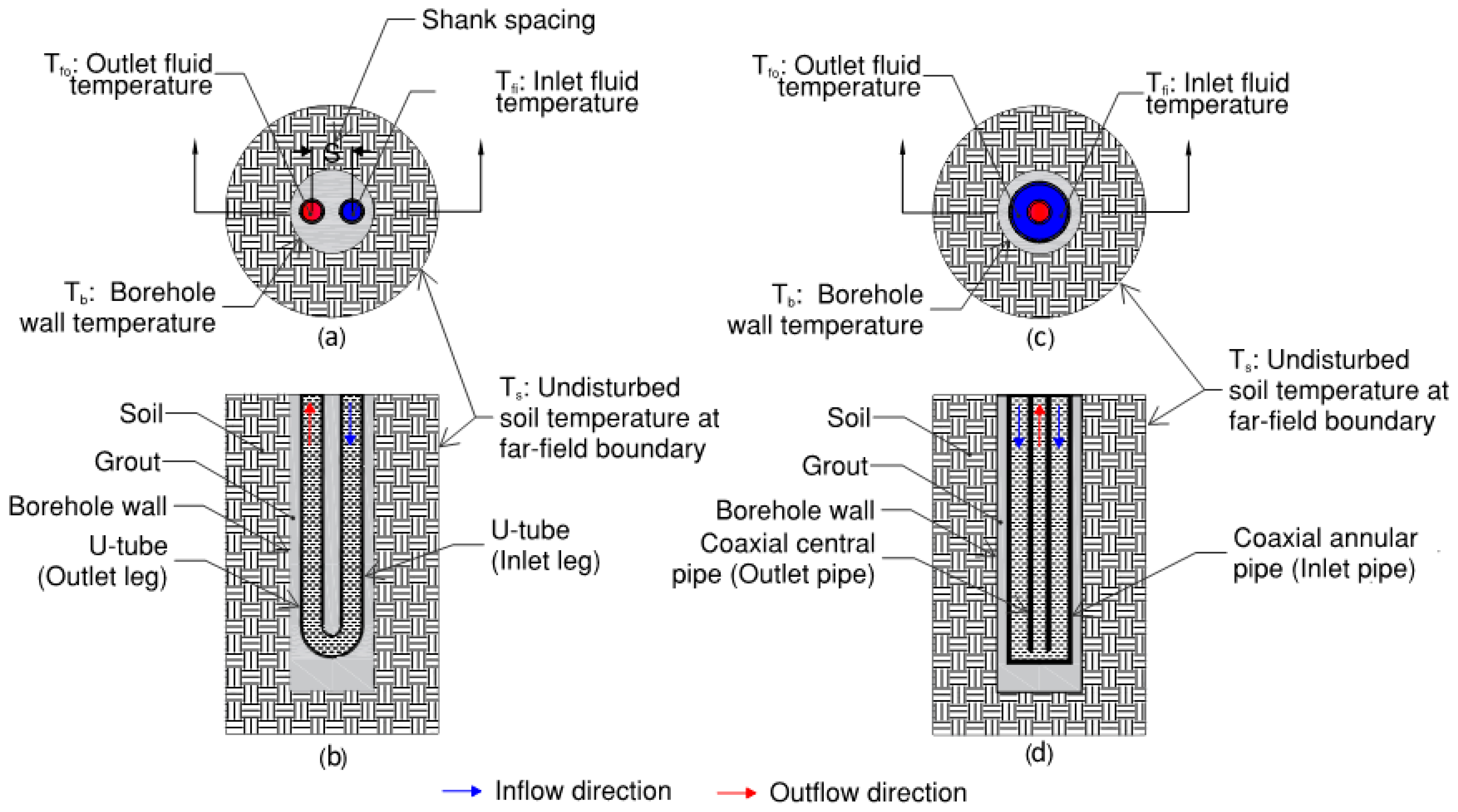
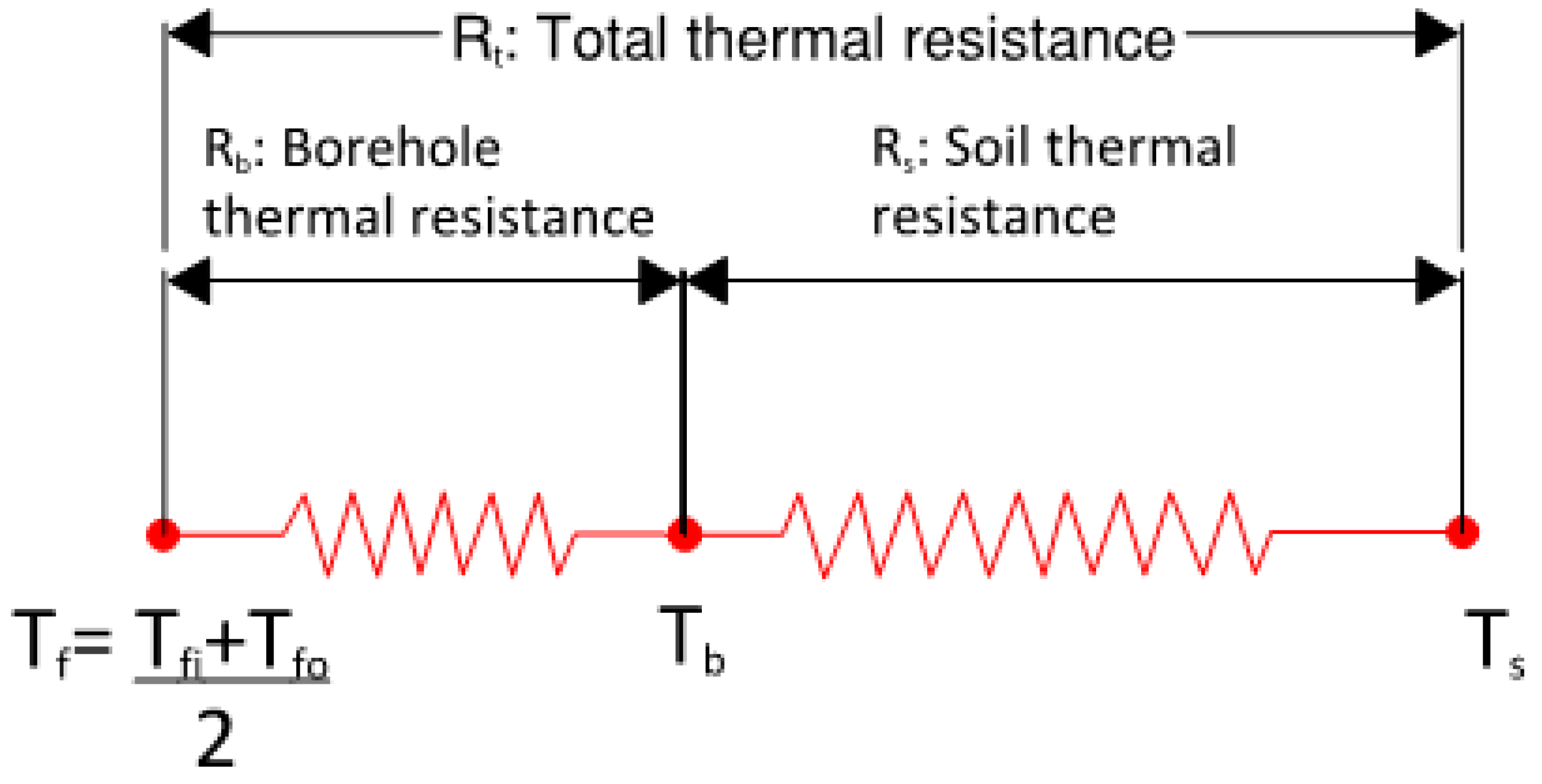
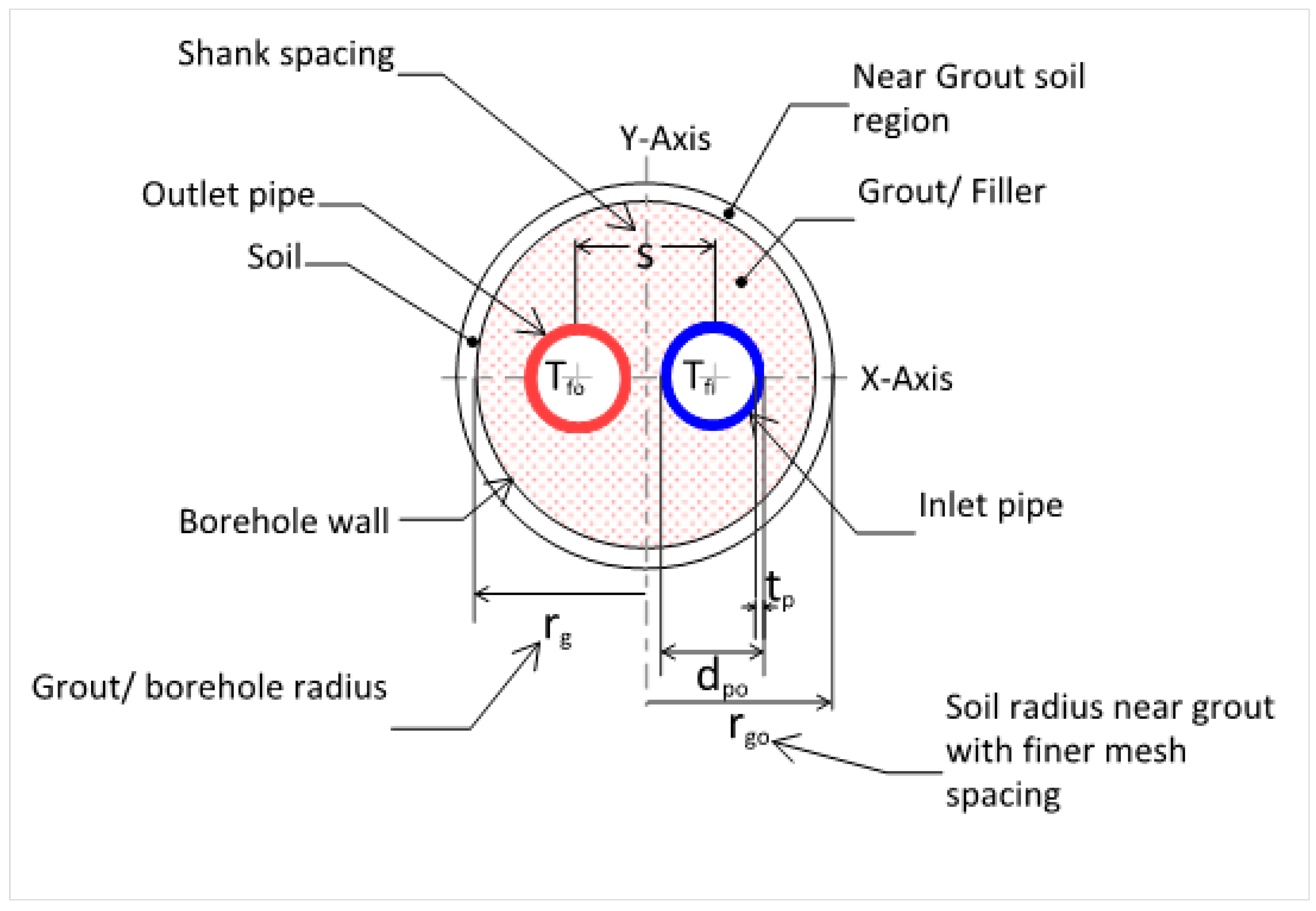
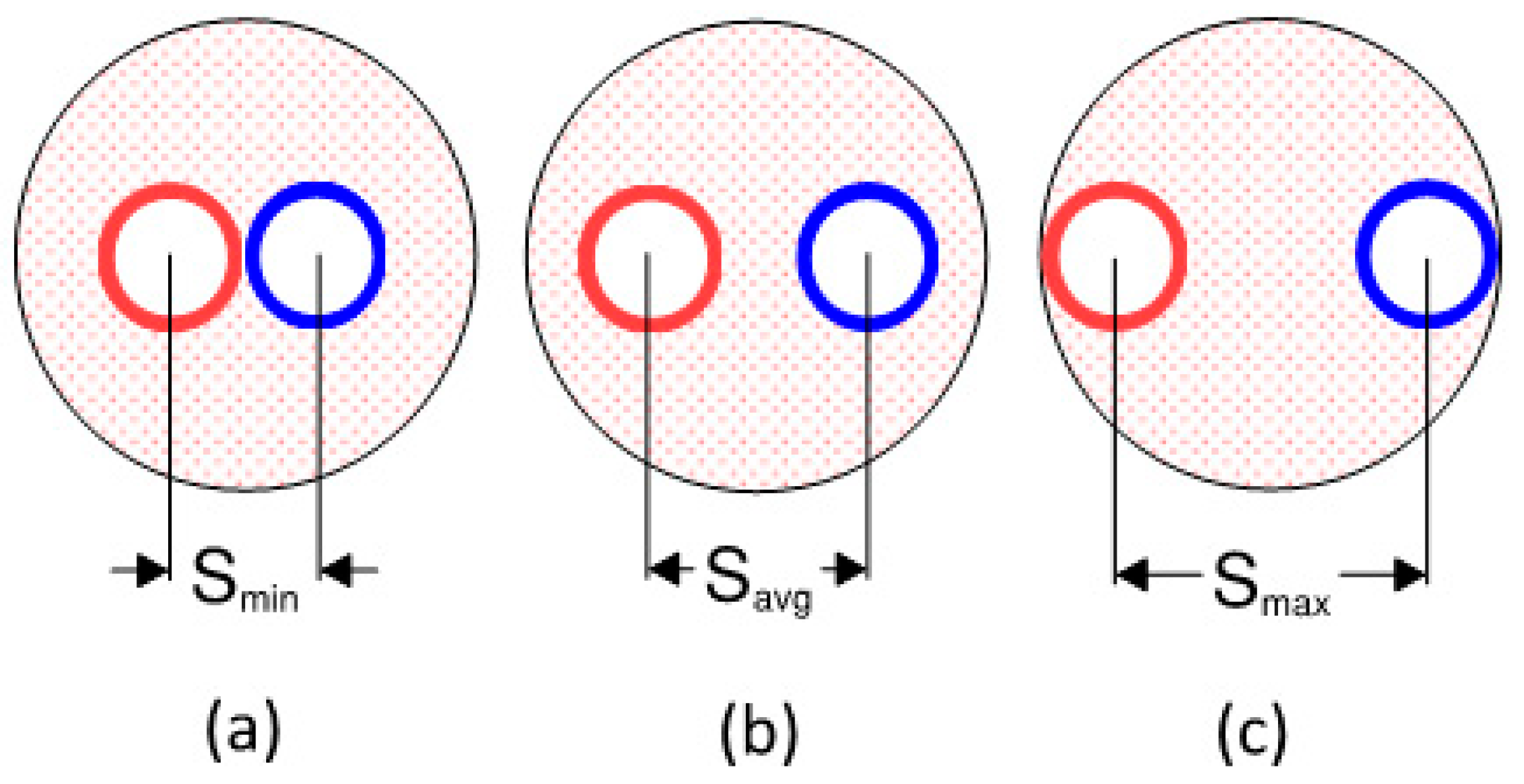

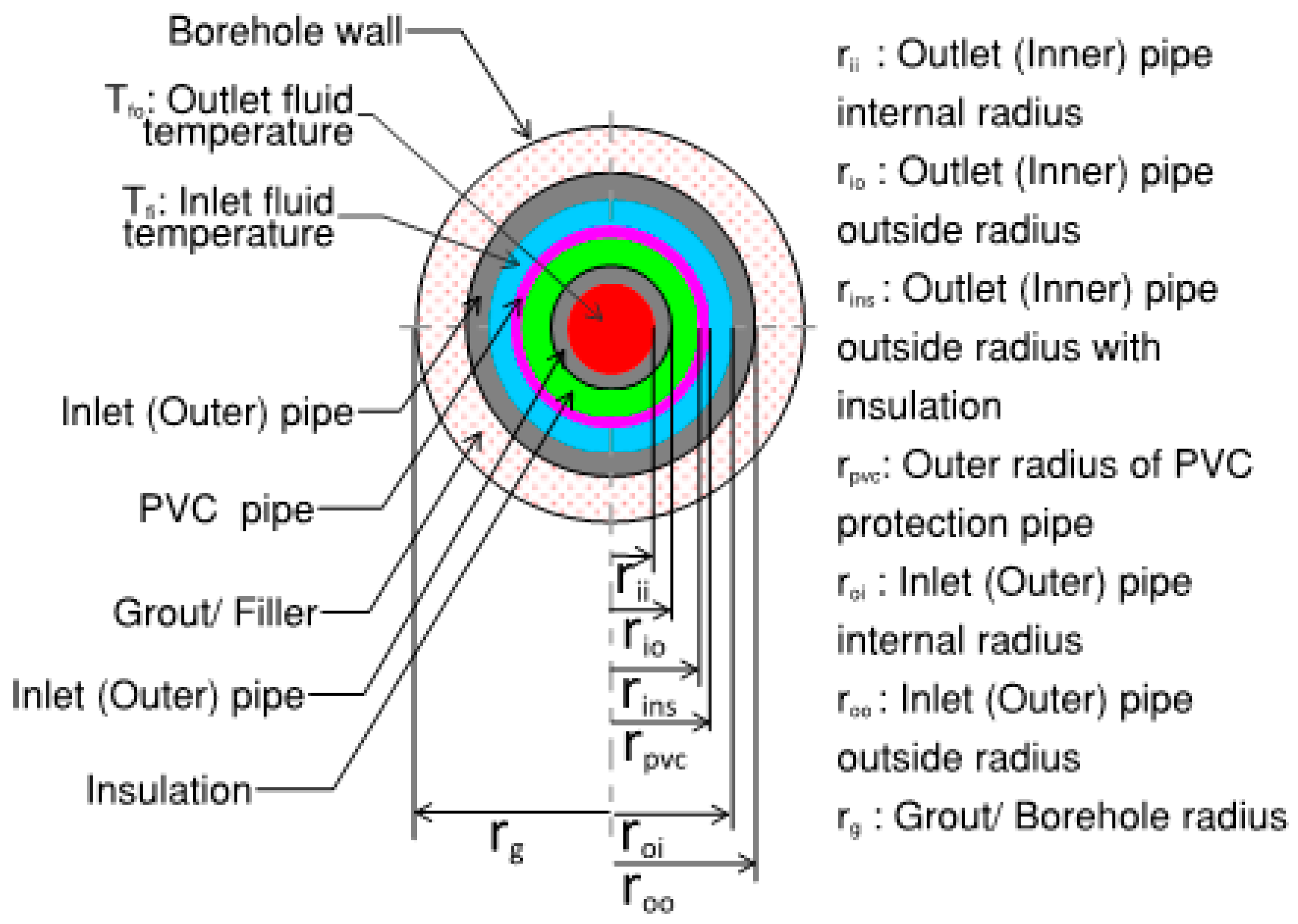
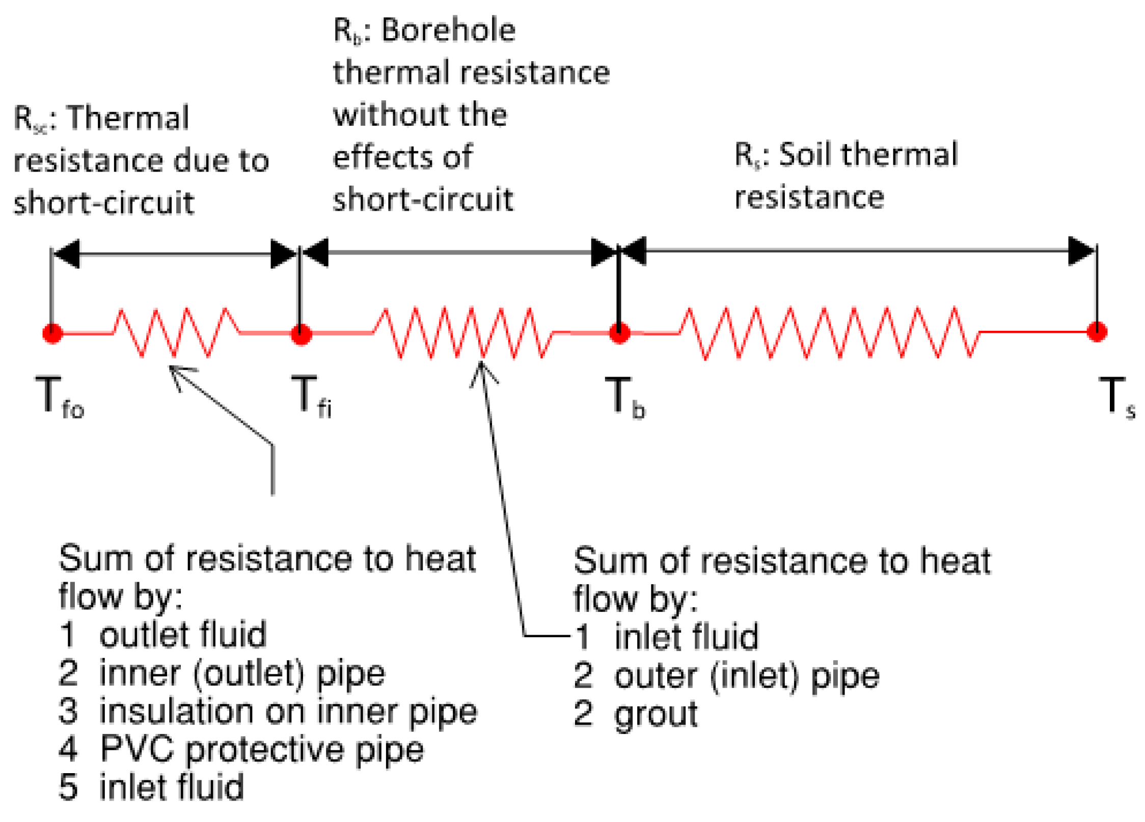
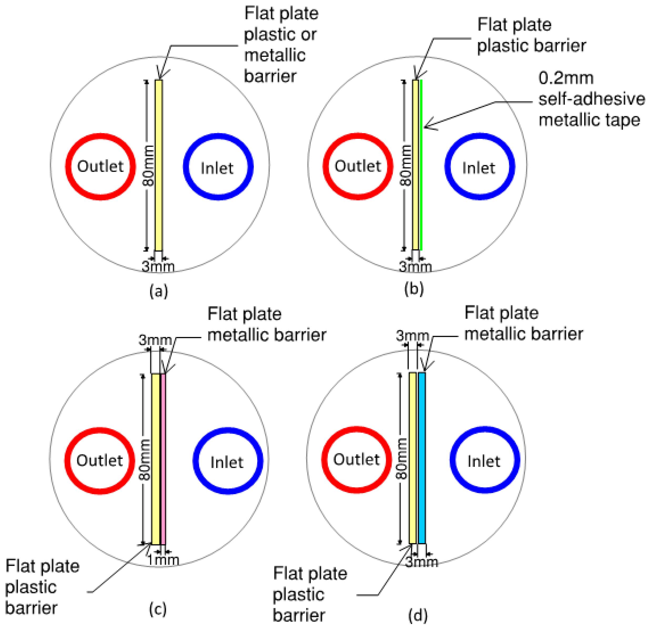
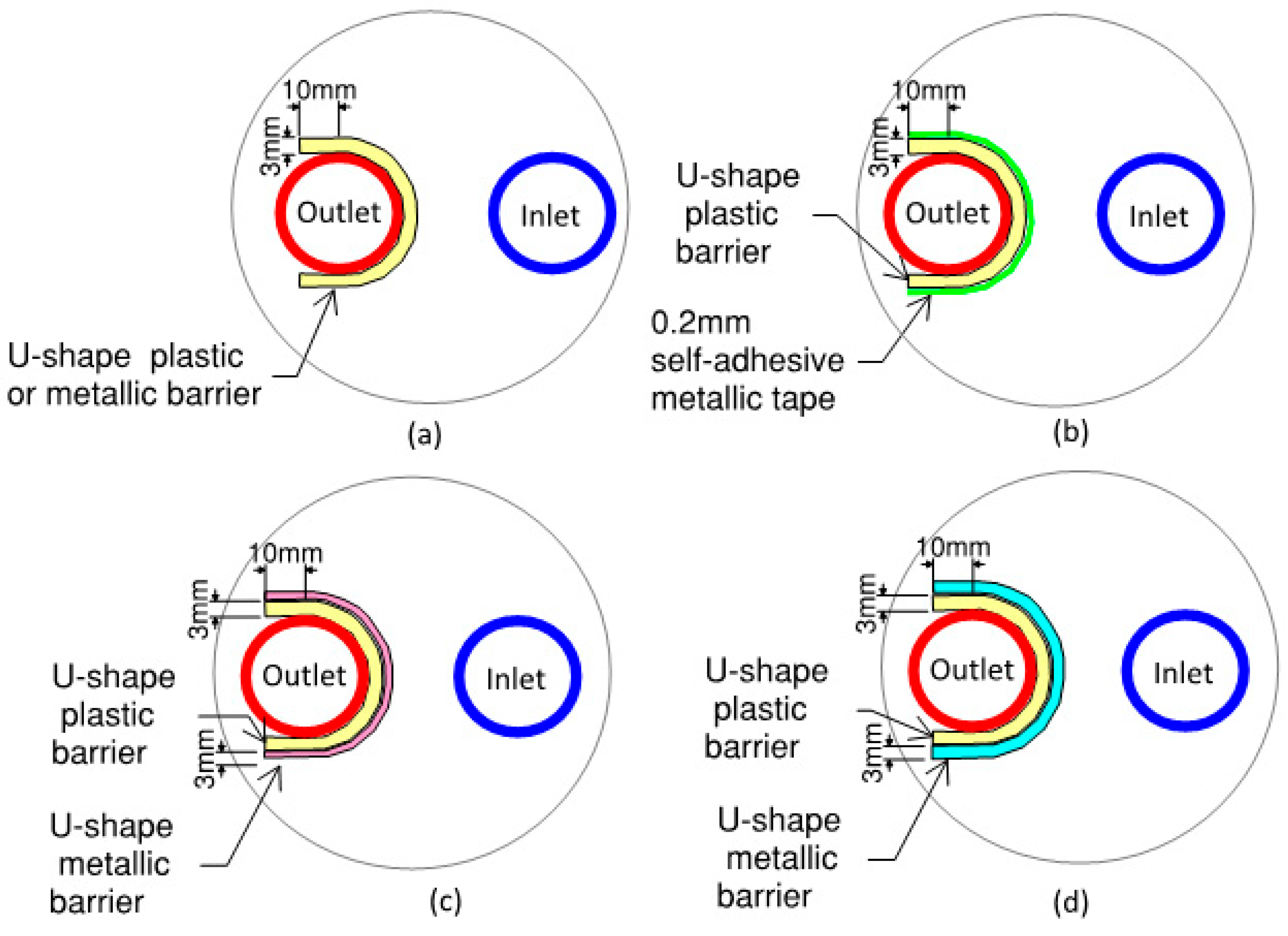
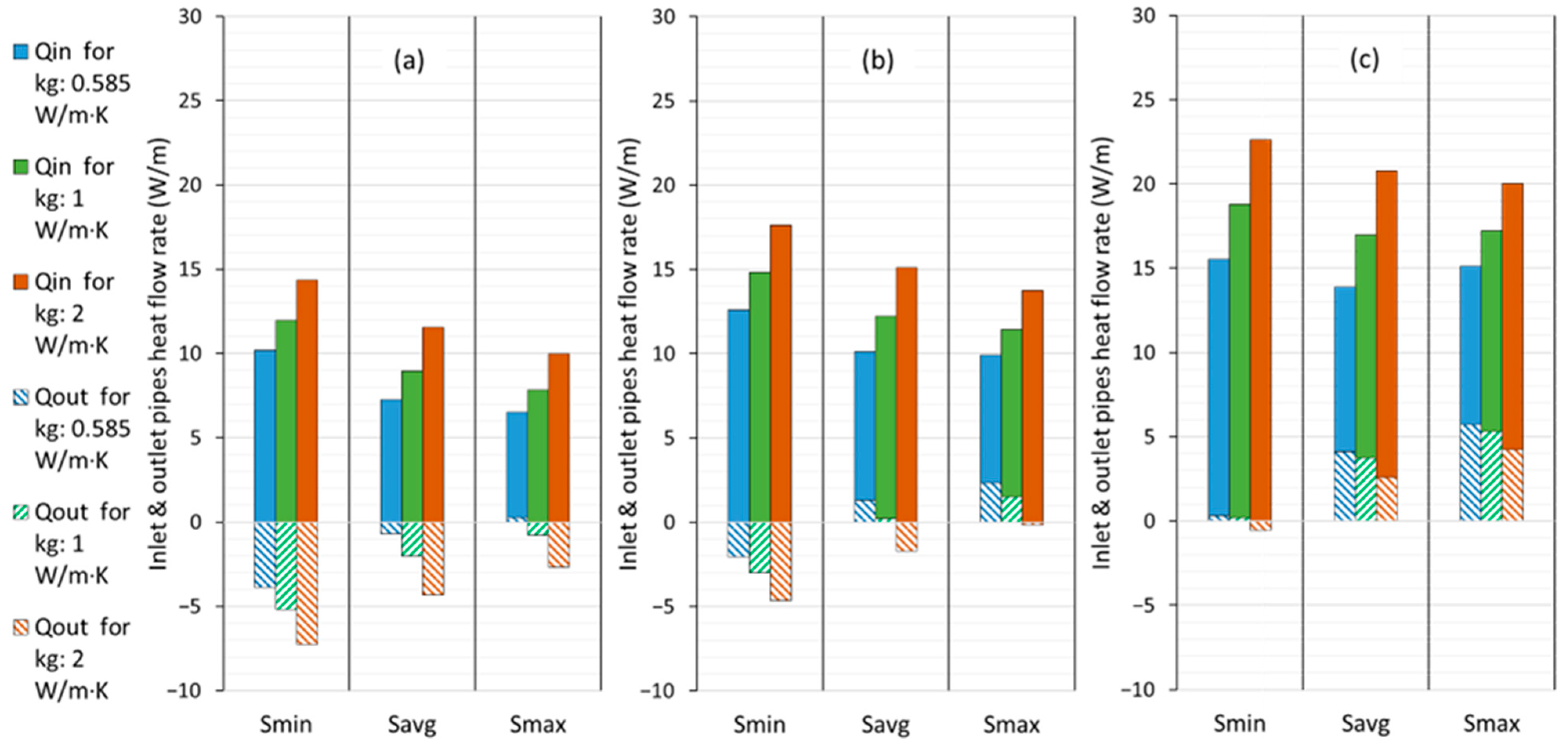
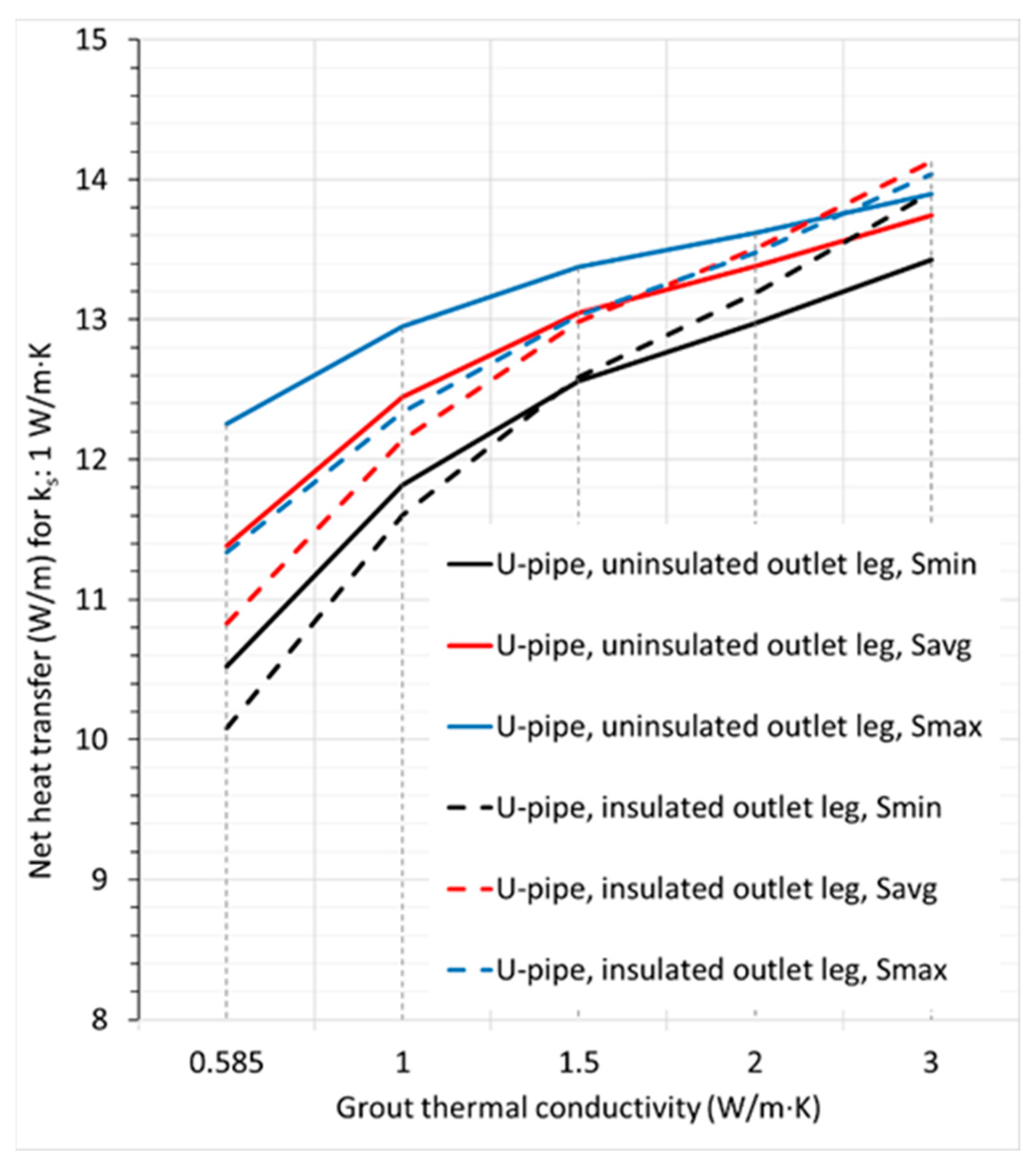
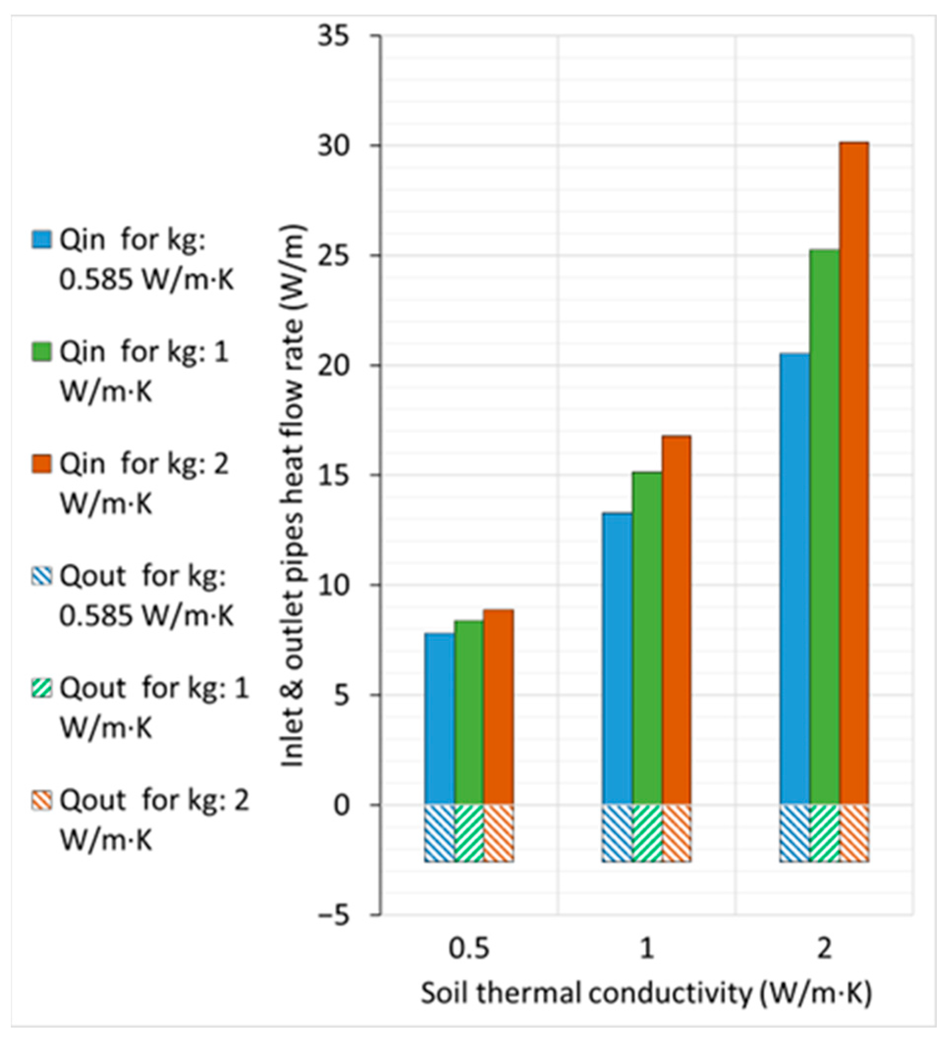
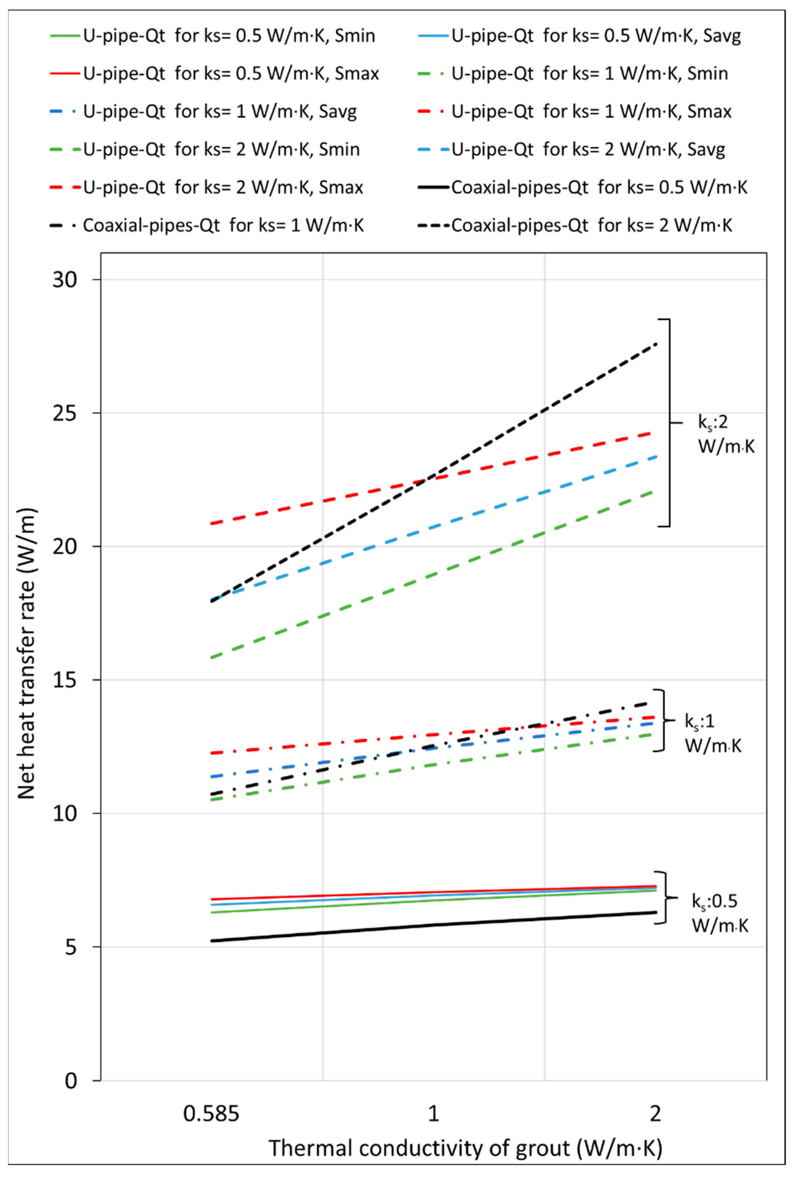


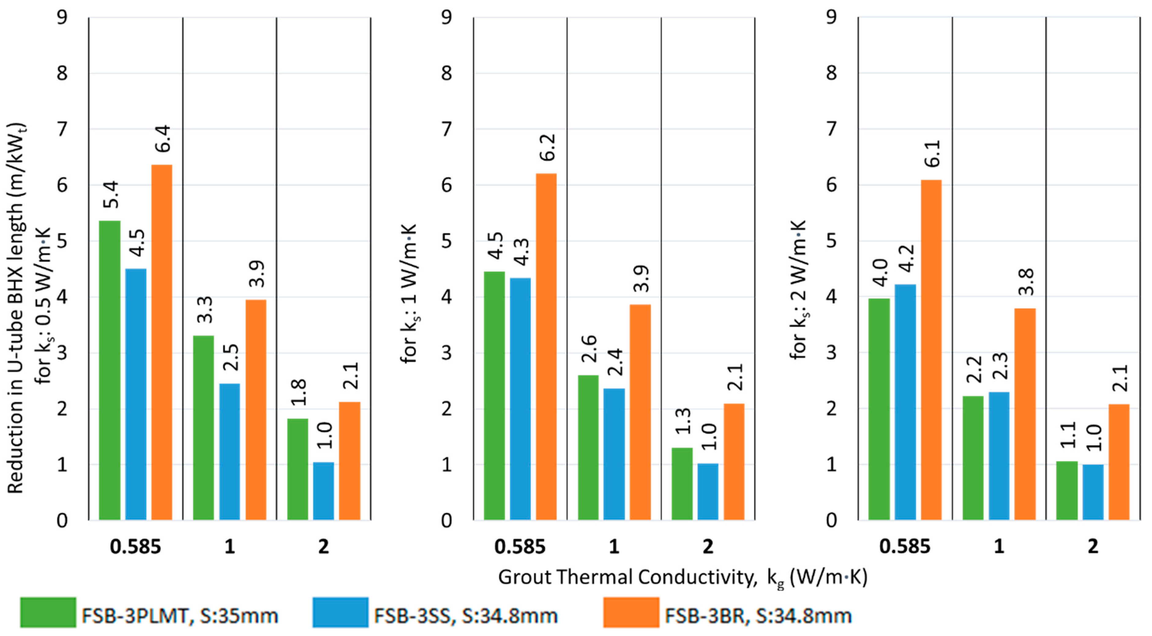
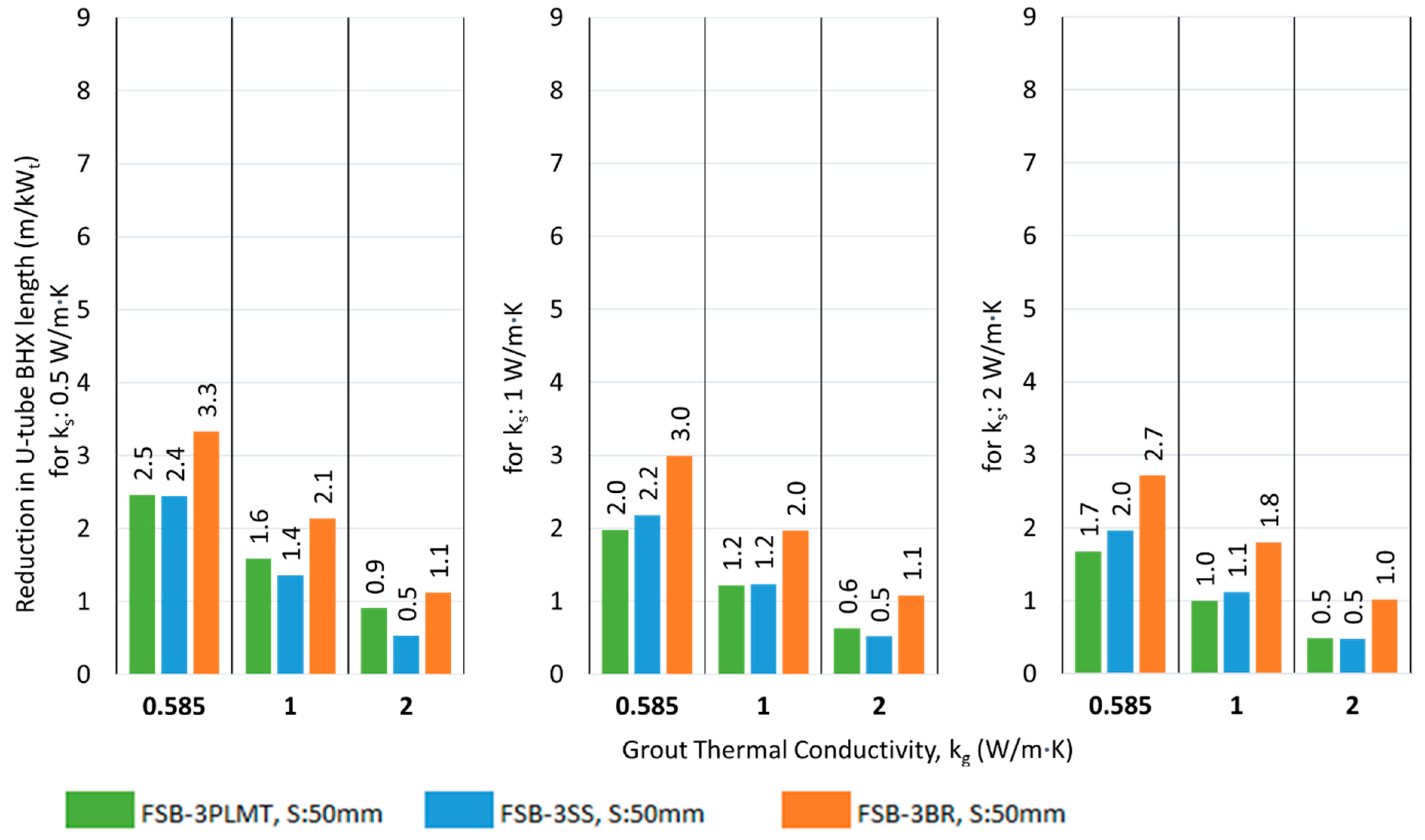
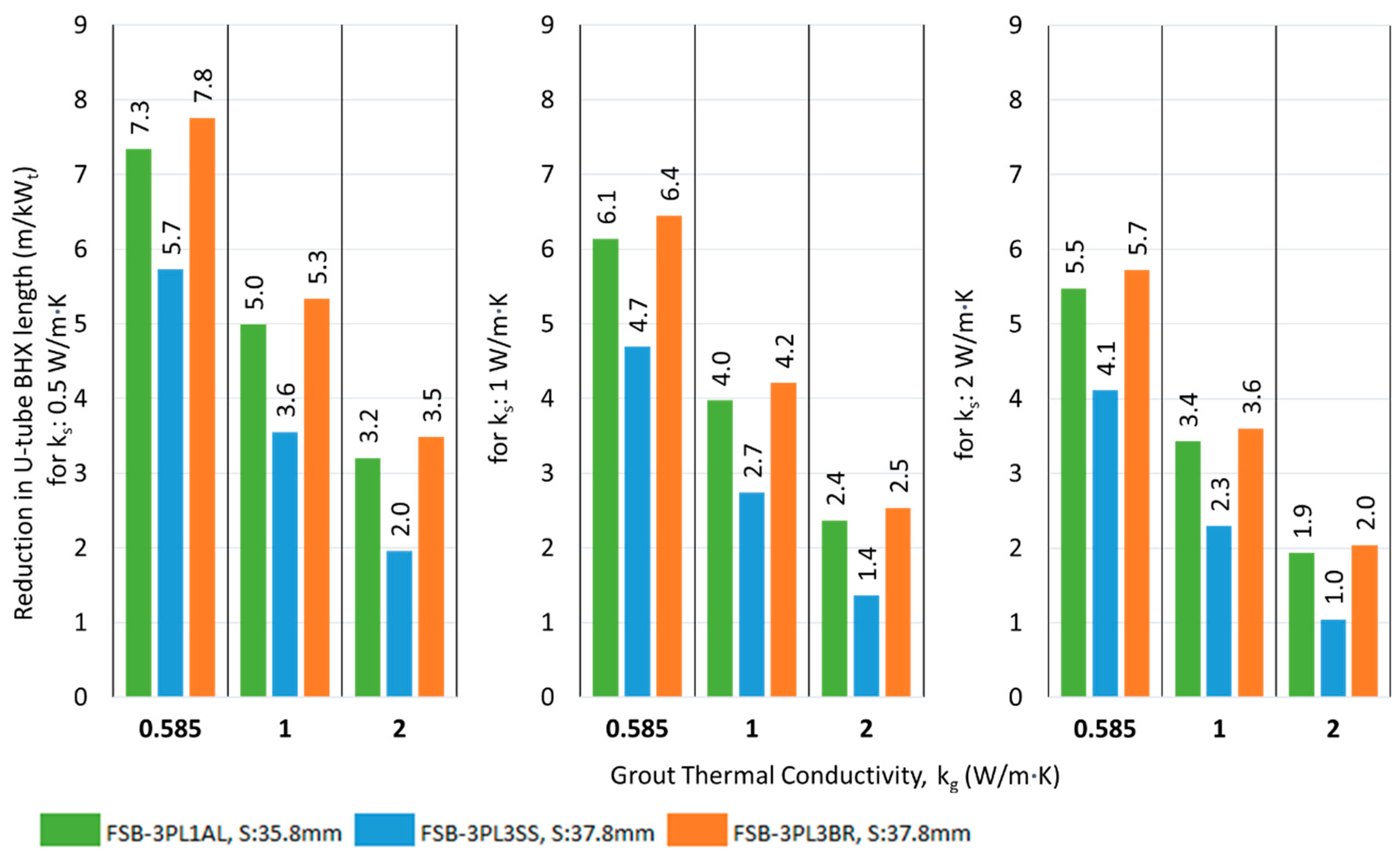
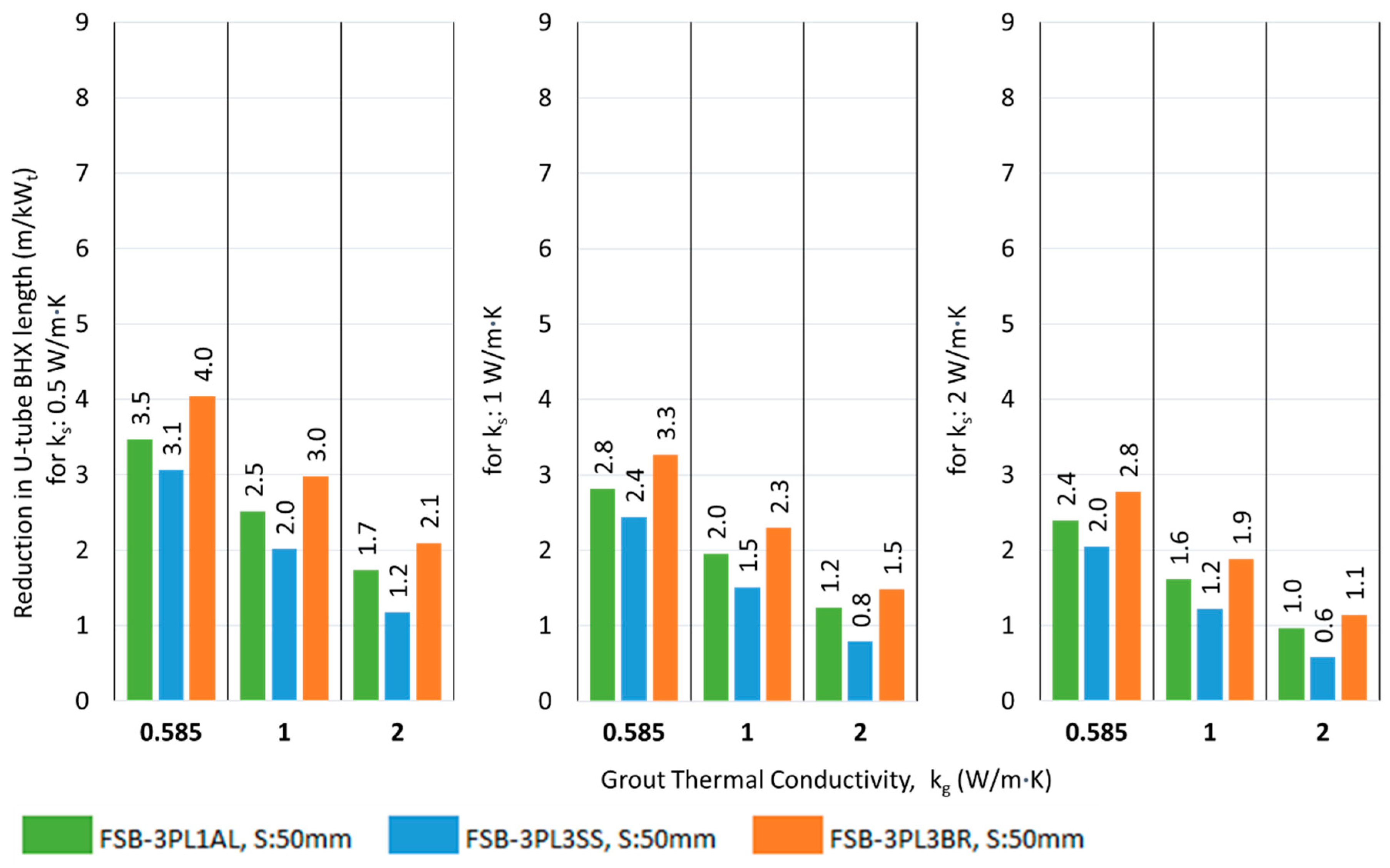
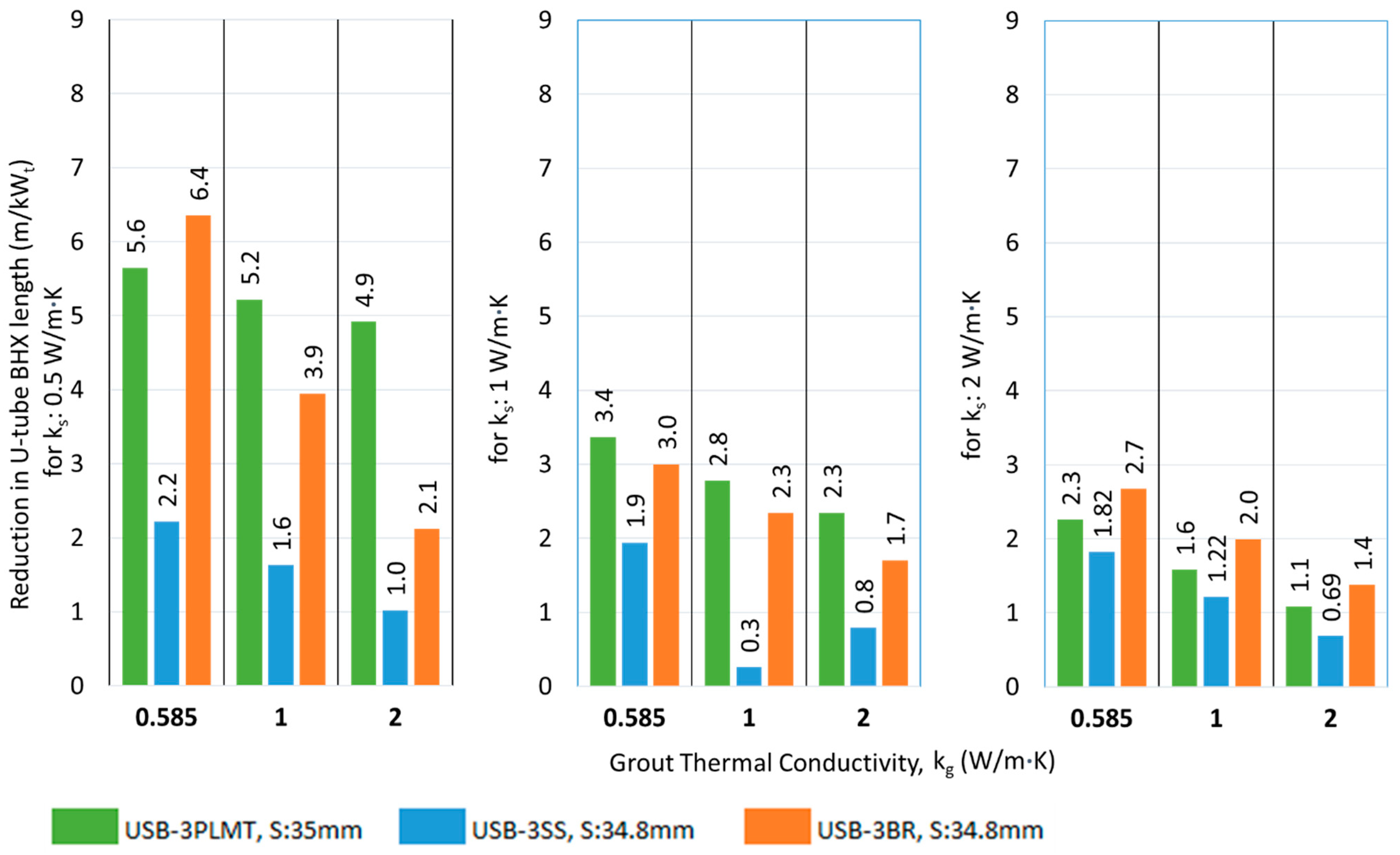
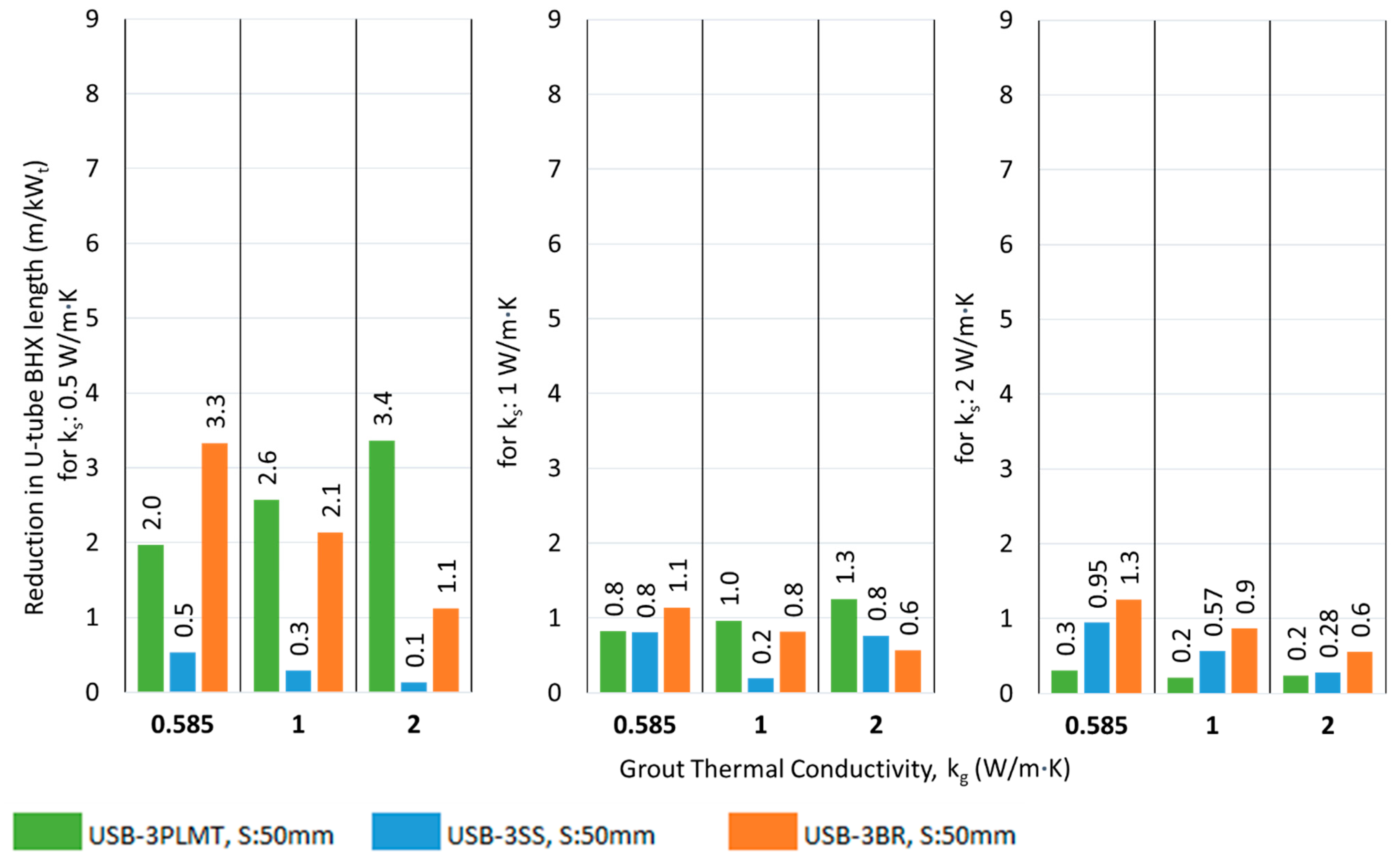
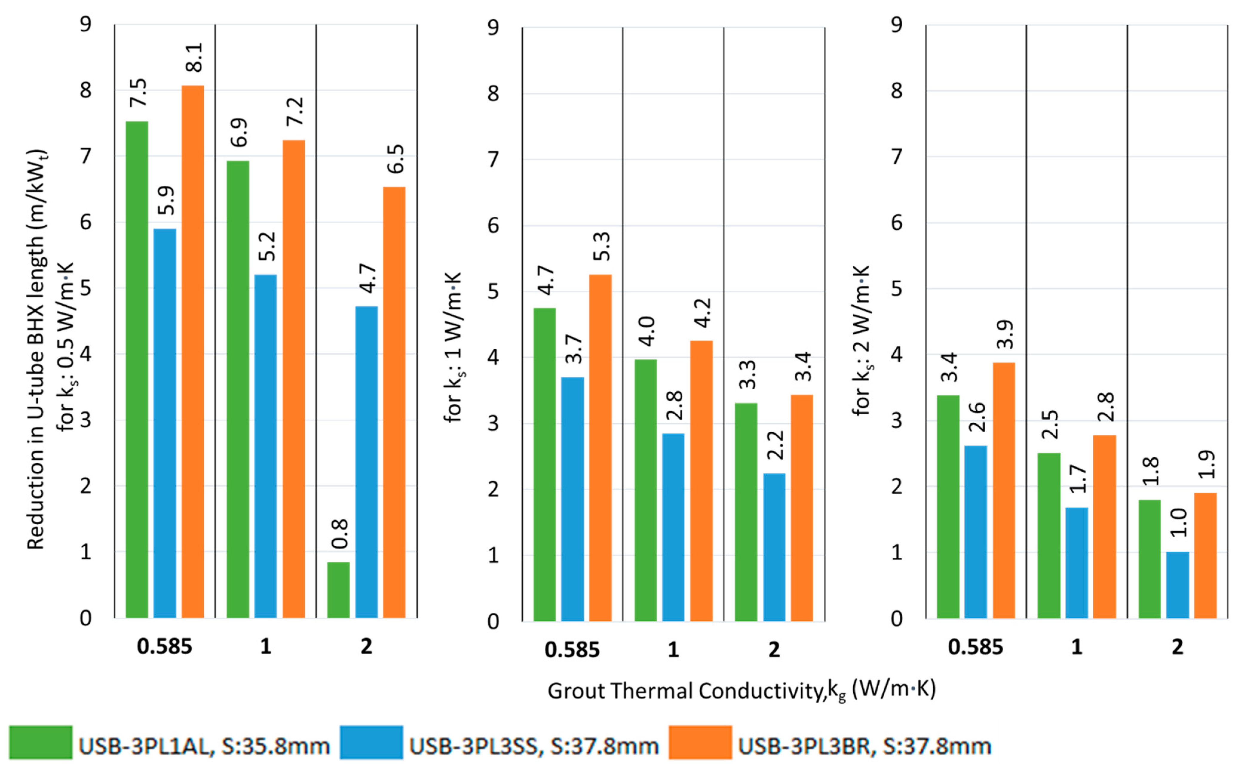
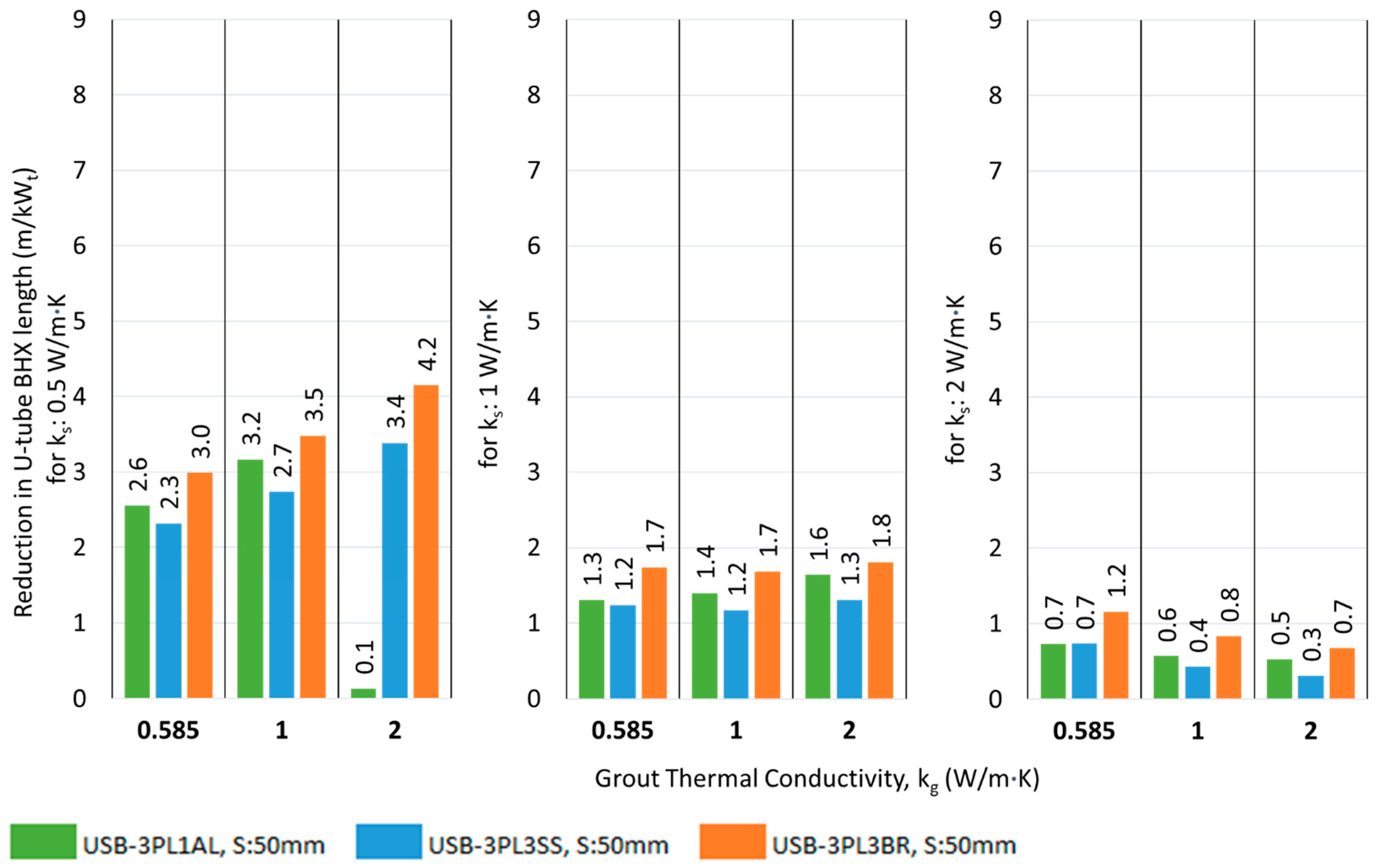

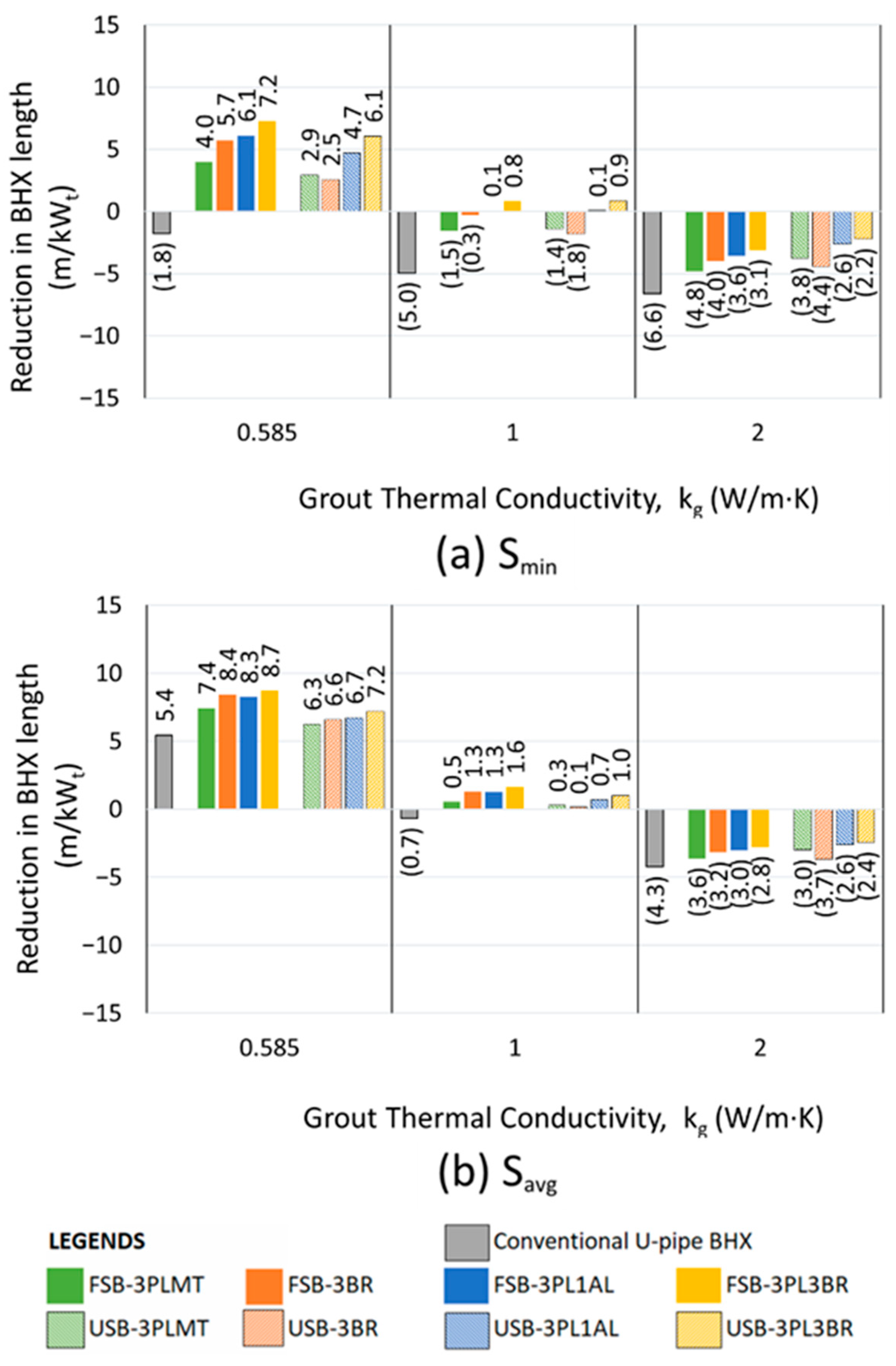
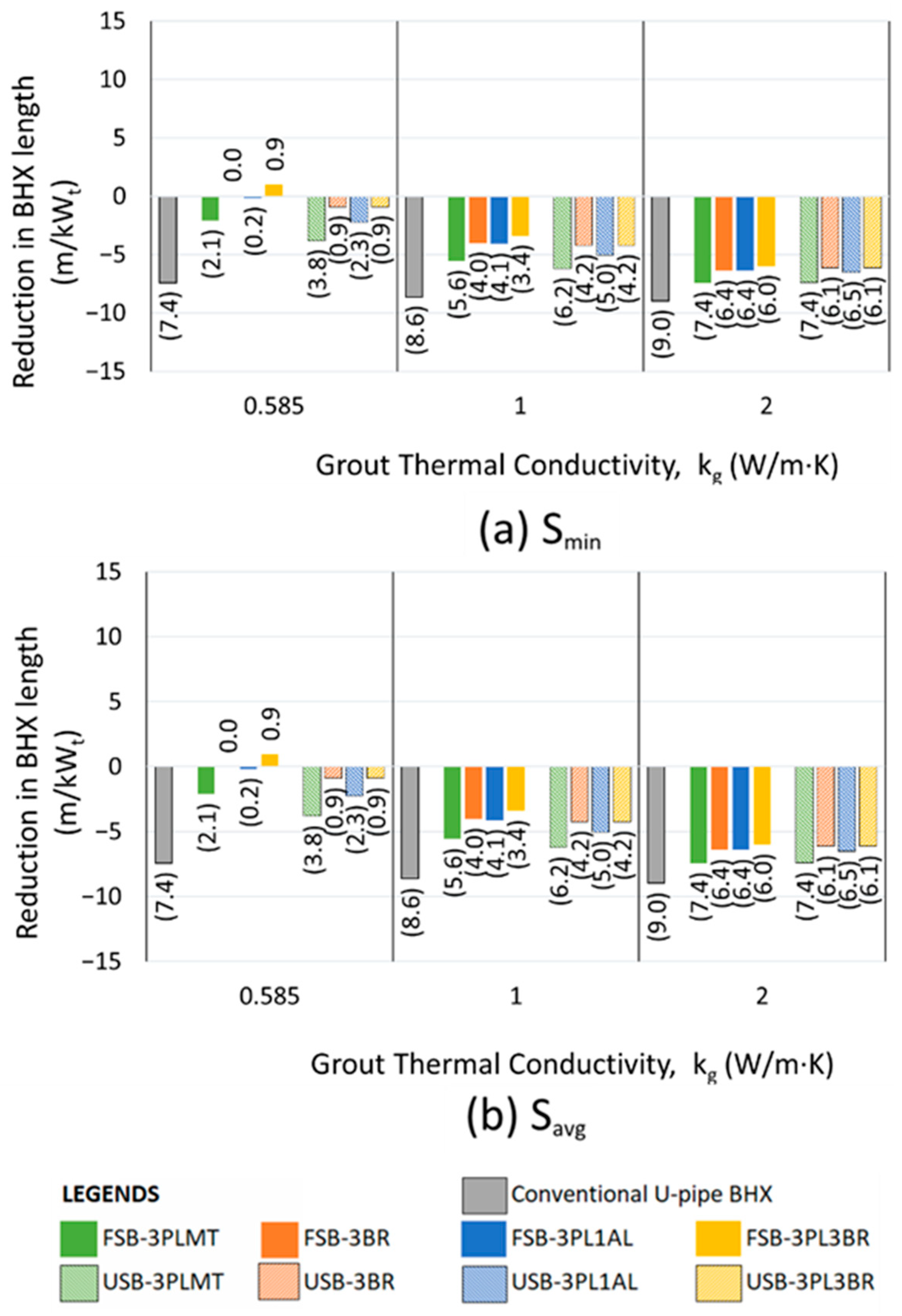

Disclaimer/Publisher’s Note: The statements, opinions and data contained in all publications are solely those of the individual author(s) and contributor(s) and not of MDPI and/or the editor(s). MDPI and/or the editor(s) disclaim responsibility for any injury to people or property resulting from any ideas, methods, instructions or products referred to in the content. |
© 2025 by the authors. Licensee MDPI, Basel, Switzerland. This article is an open access article distributed under the terms and conditions of the Creative Commons Attribution (CC BY) license (https://creativecommons.org/licenses/by/4.0/).