1. Introduction
The presence of water in ground influences its physical properties (i.e., bulk density, plasticity, permeability) and gives rise to mechanical parameters that determine the strain and stress inside (i.e., cohesion, effective stress, pore water pressure, friction). These parameters are essential for design and calculation in geotechnical structures, so they have been extensively covered in the standards and procedures currently used in ground engineering [
1,
2,
3,
4], and there are numerous case studies in the scientific literature in which this interaction is highlighted [
5,
6].
The interaction between groundwater (a mass of water moving through a porous medium driven by gravity and pressure forces) and ground engineering works has been widely addressed in basic handbooks of soil mechanics and geotechnical engineering since this field of science was established [
7,
8]. Analytical solutions, graphical methods (flownets) and numerical modeling have been traditionally used to solve problems related to groundwater flow and its interaction with geotechnical structures. Among them is the case we deal with herein: an excavation with sheet pile walls where seepage occurs under the retaining structures. Harr was the first to extensively study this subject in his book
Groundwater and seepage [
9]. He included the studies of other authors based on analytical solutions to calculate seepage, hydraulic gradient and pressure under retaining structures. The results were gathered in plots containing curves (abacuses) that are still depicted in current standards, recommendation guidelines, and research papers, but, in all cases, without taking into account the anisotropic nature of porous media [
10,
11,
12]. Nowadays, despite the widespread use of numerical modeling to calculate these basic parameters for design [
6,
13], type curves or universal abacuses are a basic tool that guides engineers in a first approximation whereby they design the geotechnical structure. In fact, in this work, we use numerical modeling to develop the type curves so that once they have been depicted, we can obtain the results without resorting to numerical calculation. The main contribution of this methodology compared to the traditional ones is that the dependencies between dimensionless groups are universal, so a single abacus can solve scenarios with different geometries, physical parameters or boundary conditions.
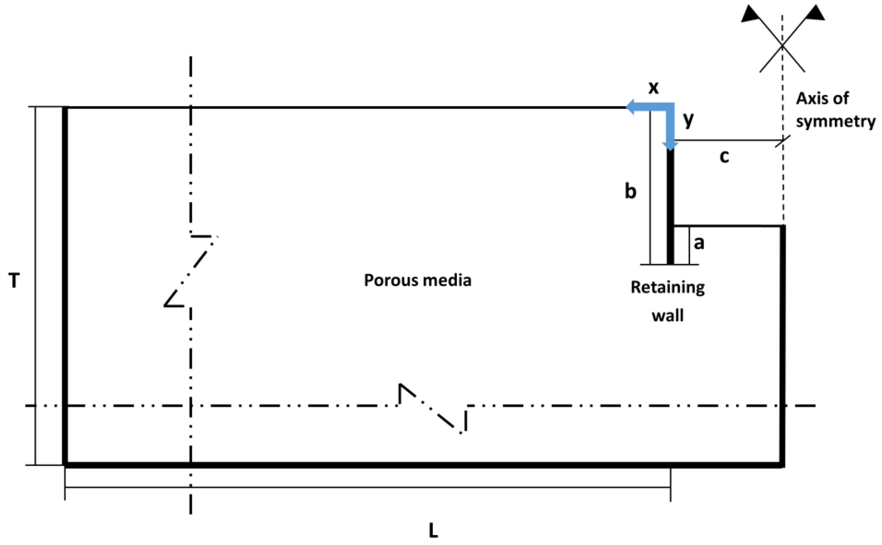
The basic problem we focus on in this study is shown in
Figure 1. It deals with seepage under sheet pile structures, which can extend to metal sheeting, diaphragm walls, cut-off walls and cofferdams. Groundwater movement occurs parallel to the XY plane and flows from the back and under the retaining structure to the inside of the excavation. The transversal extension is long enough to prevent corner effects [
14], so the seepage is calculated per unit transversal section. The vertical and horizontal extensions are assumed to be long enough that the groundwater flow is not affected by them. This means that, even though T and L are finite for practical purposes, according to this hypothesis, they might be considered infinite. To clarify this aspect and confirm this hypothesis, two characteristic lengths are defined (T* and L*). If we consider an infinite scenario, the extensions through which 95% of the total groundwater volume flows are the characteristic lengths.
By means of numerical simulations carried out with Modflow, a powerful numerical method to solve flow in porous media [
15] and a definition of the dimensionless groups that govern the solutions, three type curves were determined to directly obtain seepage. For the first time, anisotropic media are considered when the vertical depth and horizontal length are not influencing groundwater flow. Variations in hydraulic conductivity can be easily set in Modflow, so this software is frequently used in geotechnical applications to solve groundwater discharge in excavations [
16,
17,
18]. Similar methodologies, including dimensional analysis, numerical simulations and the graphical shape of type curves, have been applied in works related to ground engineering [
19].
This paper has been structured so that the methodology contains the procedures carried out for the elaboration of the type curves, which are presented in the Results section. A theoretical case study is applied as an example to highlight their potential applications.
2. Mathematical Model
As previously mentioned, the general procedure to estimate seepage under geotechnical structures is based on graphical resolutions (flownets), analytical techniques or numerical methods that solve the continuity governing Equation (1) for steady flow in porous media [
20]:
Equation (1) is a combination of the fluid continuity equation,
(5), and Darcy’s constitutive equation in anisotropic media [
21],
and
(Equations (3) and (4)).
is the hydraulic conductivity (m·s
−1), and
the hydraulic or piezometric head (J·N
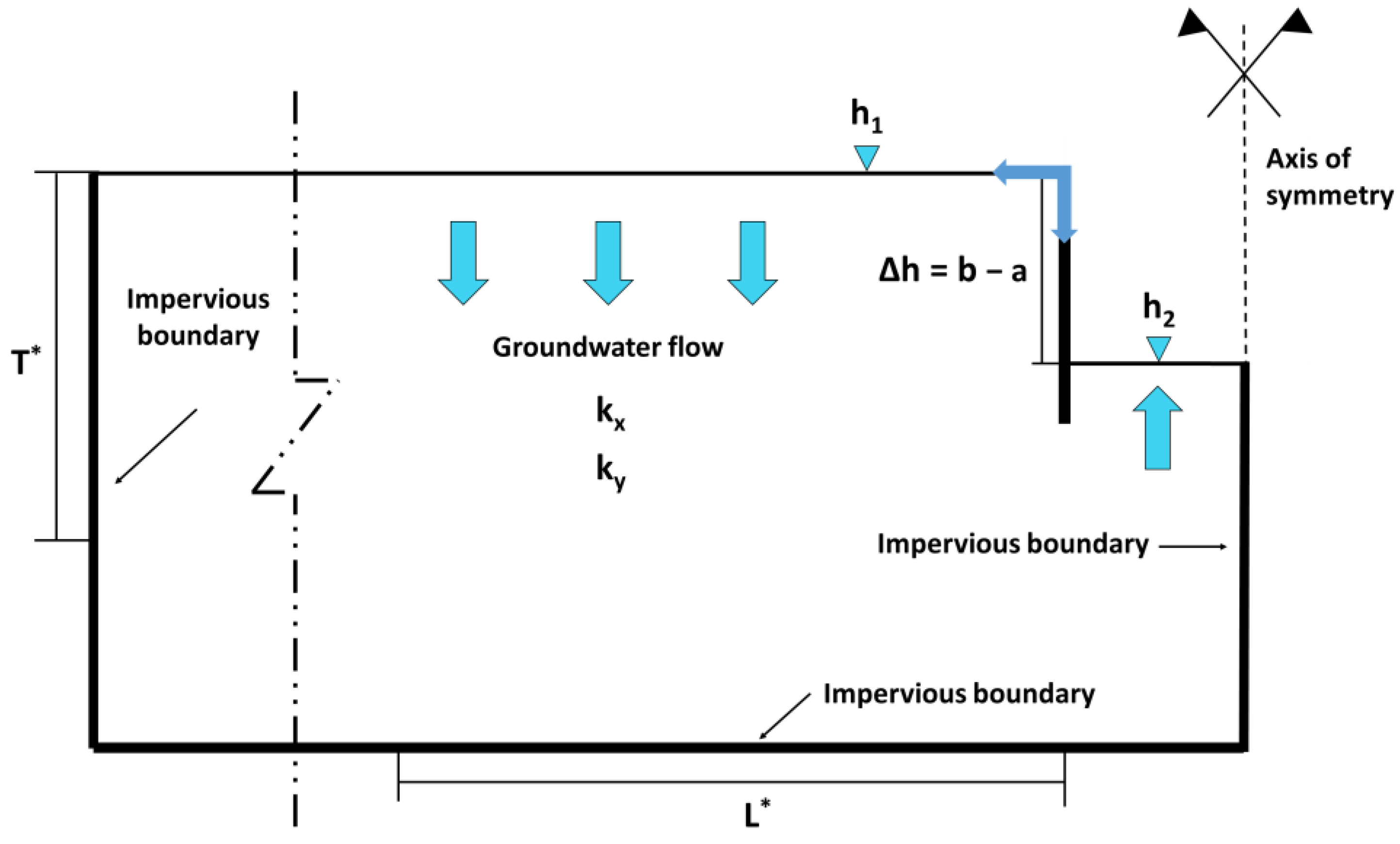
−1 or m), measured in the y direction. Equations (6) and (7) represent the first-class mechanical conditions at the surface boundaries, that is, the position of the original piezometric level and the level after depletion (inside the excavation). These are called the Dirichlet condition, and the water potential gradient values (
) drive the flow since
The imposition of these constant hydraulic potentials at the upper boundaries of the porous media gives rise to a velocity field that depends on the coordinates
(Equation (2)). The second-class boundary condition, or the Neumann condition, corresponds to the impervious limits of the scenario and the impenetrable retaining structure, as given in Equations (8) and (9). The existence of anisotropy in the hydraulic conductivity exerts a relevant influence on this velocity field. Finally, the domain’s left, bottom and right boundaries and the lines along which the structure and the soil are in contact represent a no-flow (impervious) boundary condition or the Neumann condition. Note that in all cases,
, so the
matches the position of the bottom of the excavation.
Finally, groundwater flows from a constant, head-top boundary condition (
) located at the back of the wall inside the excavation, where another constant head boundary condition (
) is set at the bottom (
Figure 2).
3. Methodology
To elaborate the type curve, the procedure requires numerous simulations, one for each boundary condition and value of the parameters involved in
Figure 1 and
Figure 2. During this process, the aim is to cover the widest possible range of monomial values, making it easier to depict the type curve. The specific values of the geometric and physical parameters and boundary conditions have been chosen to be compatible with the design and nature of the ground. In particular, the anisotropy ratio of hydraulic conductivity has varied between 1 and 10, the b/c ratio between 2 and 7 and the a/b ratio between 0.25 and 0.75.
Every simulation yields a solution (a value of , and ) that is assigned to a point in the plot. With a sufficient number of points, a trend line can be plotted, giving rise to the type curve. The axis defining the graphs is related to the values of the parameters that define the scenario, all gathered in dimensionless groups. In the scientific literature, these graphically depicted type curves are often referred to as universal abacuses or universal curves, and they are frequently used in geotechnical calculus and design.
Dimensionless groups were assembled using discriminated non-dimensionalization, a technique that has been applied in anisotropic scenarios involving hydraulic conductivity (with
and
) to solve problems of soil consolidation, seepage under dams and heat transport in aquifers [
22,
23,
24]. This technique has allowed us to determine the parameters according to the two dimensions of the problem
, that is,
,
and
(in the
direction) and
,
,
and
(in the
direction), so every monomial respects the basic rule of including only parameters defined in the selected direction. A general description of the procedure can be found in [
25]. The contribution of this approach to Darcy’s flow in anisotropic porous media was described in [
26]. The dimensionless groups obtained are summarized in
Table 1.
According to the Pi Theorem [
28], the group containing the unknowns
,
and
and
can be expressed as a function of the rest (Equations (10)–(12)).
To define the functions and , instead of obtaining their analytical solution, numerous simulations have been carried out to depict the monomial with unknowns versus the two groups included in the argument. So, the type curve directly defines the functions. Four scenarios have been simulated to verify these dependencies. The verification process is accomplished by changing the values of the parameters included in the arguments but keeping a specific value of the monomial constant. This way, if the values of the monomial with unknowns do not change for each simulation, Equations (10)–(12) are considered valid.
Table 2 summarizes an example carried out to verify the dependencies.
The expression of Equations (2)–(4) are graphically depicted by a set of abacuses including the monomials of
Table 1. To cover a broad range of geotechnical design geometries, three type curves were included in each graph.
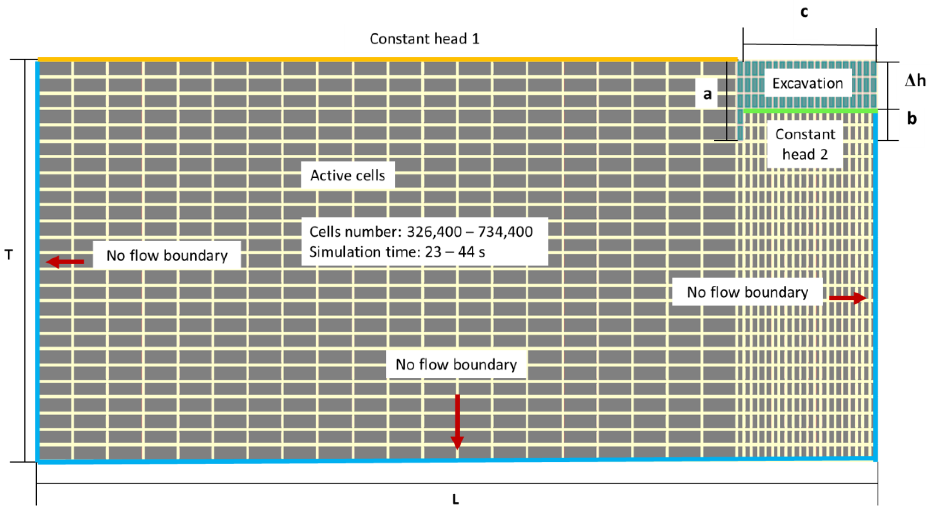
To define every point of the type curves, specific cases were solved numerically with Modflow. Every one of them had particular geometrical and physical parameter values and boundary conditions. A general scenario of a simulation is depicted in
Figure 3.
A total number of 132 simulations, each of them taking an average of less than 1 min to compute, were carried out to depict the universal dependencies of Equations (10)–(12). From the different solver packages available in the software, the geometric multigrid (GMG) was selected, as the convergence had the best fit. The models were run in steady state conditions after checking that the transient period lasted no more than two days in every simulation. The Zone Budget tool was executed in each simulation to obtain the groundwater flow from different regions of the scenario. The cells located on the surface and at the back of the retaining structure were assigned to zone budget one (yellow cells in
Figure 3), and those located at the bottom of the excavation were assigned to zone budget 2 (green cells in
Figure 3). Additionally, a further subdivision of the zone budget was carried out in each simulation. A point located at a characteristic depth or length was determined so that 95% of the discharge flowed between this point and the retaining structure. This allowed us establishing the characteristic lengths mentioned above (
and
, respectively).
The total flow from one zone budget to the other permitted us to calculate the total inflow to the base of the excavation from the back of the retaining structure: the seepage (
Figure 4). In the software,
is defined as “Constant head 1”, while
is named “Constant head 2”. In the flow network shown in
Figure 4, 22 potential iso-lines and 10 path lines are drawn. These path lines have been depicted by releasing particles on the ground surface at the back of the retaining structure using the particle tracking package to represent the trajectory of an infinitesimal volume of water throughout the scenario. Note that the space between two consecutive path lines does not really represent a flow channel because path lines are not equivalent to streamlines.
The height of the free groundwater surface (atmospheric pressure) from the coordinate axis origin and in the “y” direction represents the specific value of hydraulic head h at the boundaries. In this scenario (illustrative), = 0.0 m and = −9.0 m at the back of the wall and at the bottom of the excavation, respectively. As can be seen, the potential iso-lines vary between these two values and are perpendicular to the impervious boundaries and, in turn, the path lines are perpendicular to the potential iso-lines.
4. Results and Discussion
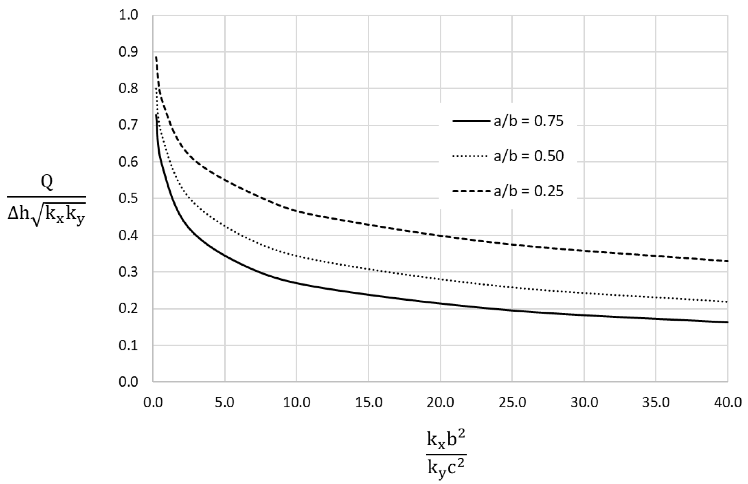
Figure 5,
Figure 6 and
Figure 7 show the universal abacuses and type curves depicted in three graphs.
Figure 5 graphically represents the dimensionless group
versus
, where
is the curve parameter. As might be expected, for a given value of
, the smaller the embedment, the smaller the
aspect ratio, and, therefore, the larger the dimensionless flow rate.
The largest variations of the dimensionless flow () occur for values of the () group between 0 and 5 (between 0.90 and 0.35). From that value, the dimensionless flow rate does not undergo significant variations for large changes in .
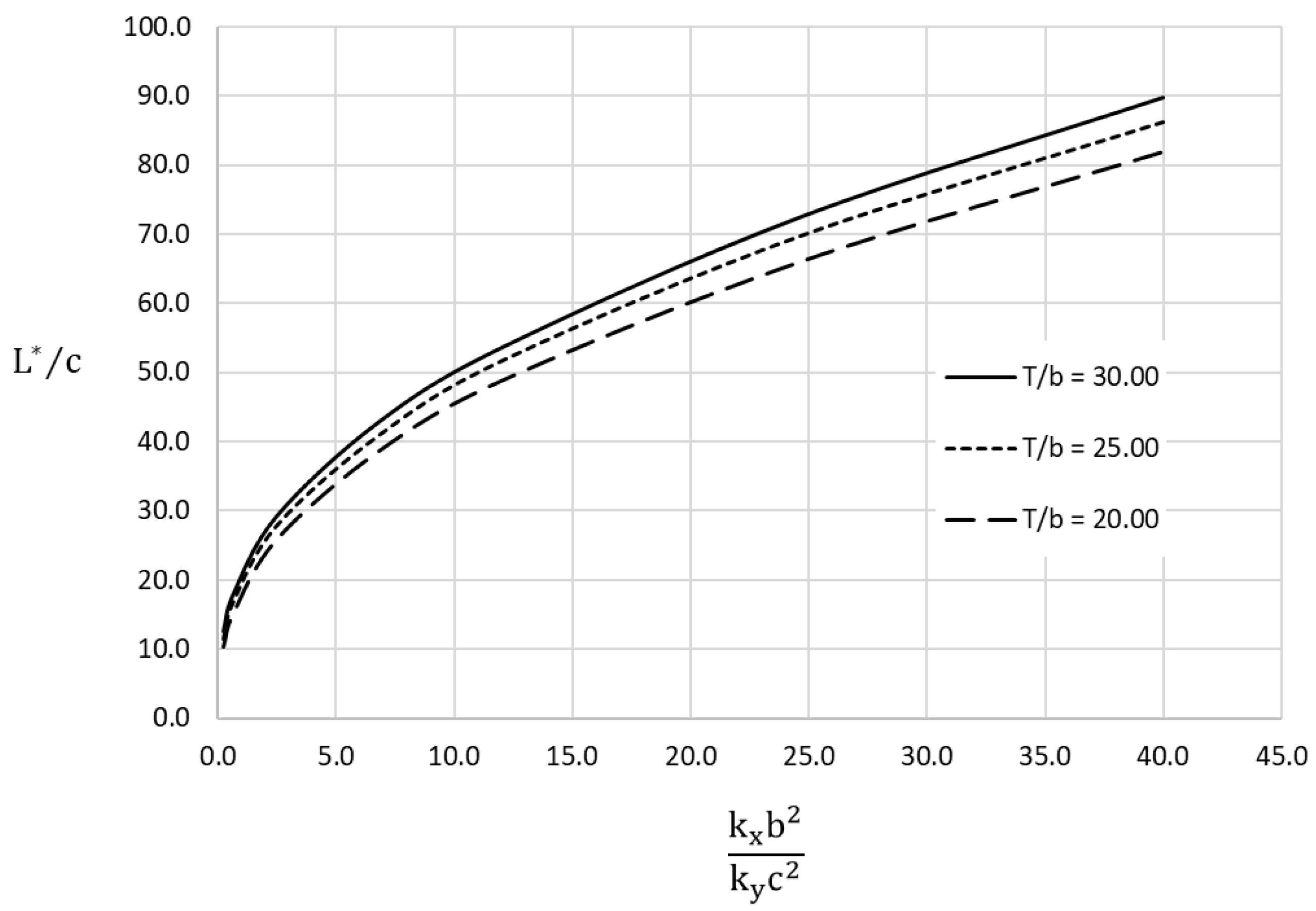
Figure 6 depicts the dimensionless group
versus
, where
is the curve parameter. For a given value of
, the smaller
, the smaller the dimensionless horizontal characteristic length. As group
increases, so does
, leaving
(width of the excavation) constant. As the anisotropy increases, the extension of the horizontal characteristic length becomes greater. This is a relevant contribution to the isotropic case.
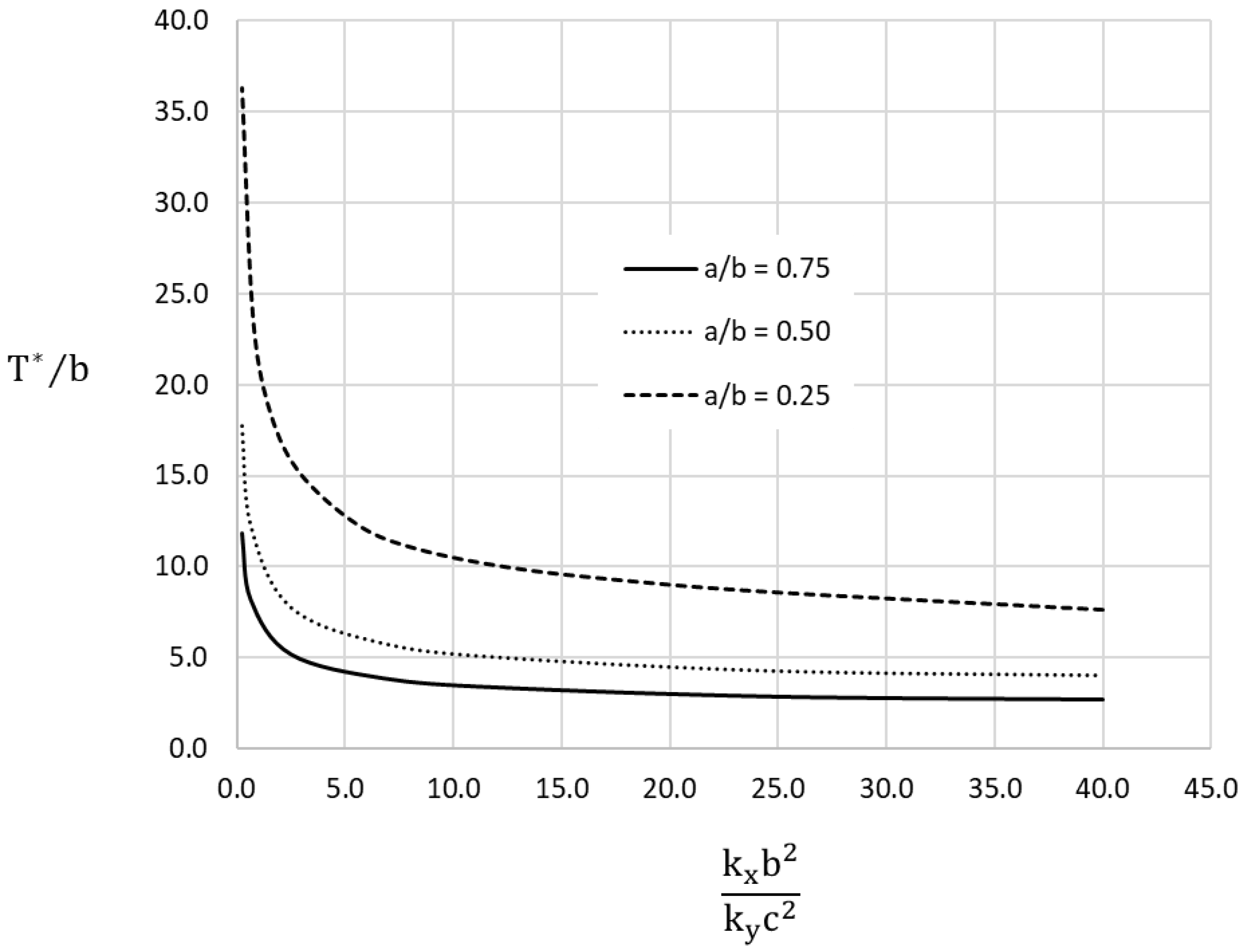
Figure 7 shows the dimensionless group
versus
, where
is the curve parameter. Large variations of
(between 35 and 5) occur for values of the monomial
between 0 and 5. Above this value, the increase in the anisotropy ratio hardly influences the dimensionless characteristic depth.
Once the geometrical and physical data are known, the type curve is selected in
Figure 5, and the specific value of the monomial is obtained, from which the Q (seepage) is derived.
Figure 6 and
Figure 7 contain the characteristic length and depth
and
of the problem. These parameters must be previously calculated to check whether the geometry of the scenario we are working on fits the condition required to use
Figure 5. The characteristic lengths we calculated were those related to 95% of the total inflow to the excavation, so we can reasonably assume that the depth of the impermeable substratum and the extension at the back of the retaining structure are not influencing groundwater flow quantity. Once the geometrical and physical values of the parameters included in
Figure 6 and
Figure 7 are replaced with the real values (those of the scenario), we select the type curve, and parameters
and
are clear from the value of the monomial. These must then be compared with those of the real scenario
and
.
Figure 5 can be used if
<
and
<
.
Section 5 shows a practical use of the abacuses based on case studies and a theoretical example.
Two of the limitations of these abacuses are that they do not cover the full range of monomial values and only three values of the curve parameters (and ) have been chosen. Regarding the former, it might be said that the limitation is apparent since there are many combinations of geometrical, physical and boundary condition parameters that give rise to each value of . Regarding the latter, it is assumed that even if a larger number of curves were drawn, interpolation would always be necessary to obtain the not-covered values of and .
The main contribution of these universal solutions or abacuses can be highlighted by comparing them with previous results found in the bibliography. For example, in the recommendations for the cofferdam of unlimited extension in CIRIA [
10], which were based on Harr’s handbook [
9], the graphical solution for the dimensionless monomial
was a function of a parameter m, which in turn was a function of the depth embedment
and
. Since no anisotropic medium was considered, the emergence of the group obtained with discriminated dimensional analysis,
, does not apply, and
is not possible to obtain. Furthermore, although Harr referred his results to a “structure on a permeable base of infinite extent,” there was no specific geometrical value for
(aquifer thickness). This assumption involved ruling out cases where the extension or depth was not infinite but large enough, so it was not conditioning flow. The concept of characteristic length and depth,
and
, solve this aspect, and by means of
Figure 6 and
Figure 7, we check whether a specific value of depth and extension might be considered infinite (compared to an infinite scenario, 95% of the total volume of water is flowing to the excavation).
Another solution for limited scenarios, where
is conditioning flow, can be found in standards but, again, no anisotropic medium is considered. For example, in the Canadian Foundation Engineering manual [
11], the seepage is calculated from a type curve where two non-determined parameters are needed, both obtained as a function of geometrical relation: aquifer thickness, depth of excavation and sheet pile penetration.
5. An Example of Application: Definition of Characteristic Lengths
The objective of this section is to exemplify how to use the abacuses and understand the concept of characteristic length. To this purpose, three examples based on real cases, a benchmark problem and a theoretical case are shown in
Table 3. Hydraulic conductivity values have been sought from averaged values found in the literature for sands [
29].
The protocol required to obtain the seepage from the abacuses is summarized in the following steps:
From the values of variables , , , and , calculate the monomials , , .
Plot a point in
Figure 6 and
Figure 7 by selecting the suitable type curve and the value in the horizontal axis.
Project the point on the vertical axis, parallel to the horizontal. Obtain the value of and .
Calculate and .
Compare
and
with
and
. If
>
and/or
>
, the problem cannot be solved using
Figure 5.
If
<
and
<
, the problem can be solved using
Figure 5.
Plot a point in
Figure 5 by selecting the suitable type curve and the value in the horizontal axis.
Project the point on the vertical axis, parallel to the horizontal. Obtain the value of
Calculate seepage by clearing from monomial .
We applied the protocol using the geometrical and physical values included in
Table 3. The results for the three cases are shown in
Table 4.
Case 1 illustrates a scenario where the excavation is parallel to the coastline (infinite source of water), and both are connected through granular sedimentary rocks that extend far beyond the shoreline, so the characteristic extension (
) is assumed to be reached. The vertical extension, or the position of the bedrock, was not provided, so we estimated the minimum value necessary (
= 76.0 m) to calculate
from
Figure 5. In Case 2, the depth and extension where no flow boundary condition was set (impervious cells) were found to be larger than
and
. This assumes that the geometry is conditioning
and the scenario is finite. To consider the scenario infinite, the values of
should be greater than 76.2 m. Since, in this case,
<
, steps 6–10 cannot be applied to calculate
. Case 3 was set out to highlight the influence of anisotropy on the results, depending on whether it is considered or not. An increase in the
relationship from 1 (isotropic) to 10 results in a decrease of approximately 80% of the value of
. Furthermore,
and
are influenced by anisotropy, so
is approximately 90% higher and
is 60% lower when
decrease from 10 to 1. If the excavation has an axis of symmetry located at distance
from the retaining structure, the seepage is multiplied by a factor of two.
The geotechnical design of the embedded retaining structure requires specific procedures to calculate and verify the geometry and hydraulic conditions. To do this, the equilibrium of the horizontal and vertical forces and moments must be reached with a given safety factor, and the compatibility between stress and strain must be checked. Likewise, the seepage forces and pressures caused by water in the porous media system should give rise to a positive effective stress profile determined by a safety factor.
A geological survey and ground testing provide the mechanical properties and layer extensions. The procedures and recommendations are gathered in many handbooks, standards, and recommendation guidelines [
32,
33].
6. Conclusions
Three universal abacuses containing nine universal type curves are made to calculate the seepage under embedded retaining structures of an excavation (sheet piles, cofferdam, diaphragm walls and so on). The basic conditions are anisotropic media (and values of vertical depth to the impervious bedrock and horizontal extension at the back of the wall below the characteristic length and , respectively. Both lengths are calculated from the abacuses and determine the region within which 95% of the groundwater flow circulates, so the scenario can be considered infinite. The geometrical and physical data required in the abacuses are the retaining structure embedment, the structure height under hydraulic pressure, the excavation width, the hydraulic depletion and the hydraulic conductivities. The horizontal extension and vertical depth are needed to check and compare their values to those of the characteristic lengths, so we can decide whether the scenario data fit the use of the abacus related to seepage.
The mathematical procedure to obtain the dimensionless groups ruling the problem was the discriminated non-dimensionalization technique. From this methodology, six dimensionless groups are obtained: three without unknowns , and and three with the unknowns of the problem , and , and . Finally, three examples were solved to demonstrate the use of the abacuses and the concept of characteristic length, with nine steps in the protocol defined. The calculus of , , and the influence of anisotropy is addressed in the examples, noting that the decrease in the anisotropy ratio leads to an increase in and a decrease in .
