Case Report

Estimation of Low-Velocity Landfill Thickness with Multi-Method Seismic Surveys

The Neev Center for Geoinfomatics, The Fredy & Nadine Herrmann Institute of Earth Sciences, The Hebrew University of Jerusalem, Jerusalem 9190401, Israel
*
Author to whom correspondence should be addressed.
Geotechnics 2023, 3(3), 731-743; https://doi.org/10.3390/geotechnics3030040
Submission received: 9 July 2023 / Revised: 27 July 2023 / Accepted: 30 July 2023 / Published: 2 August 2023

Abstract

:
Conventional geophysical methods are suitable for estimating the thicknesses of subsoil layers. By combining several geophysical methods, the uncertainties can be assessed. Hence, the reliability of the results increases with a more accurate engineering solution. To estimate the base of an abandoned landfill, we collected data using classical approaches: high-resolution seismic reflection and refraction, with more modern methods including passive surface wave analysis and horizontal-to-vertical spectral ratio (HVSR) measurements. To evaluate the thickness of the landfill, three different datasets were acquired along each of the two seismic lines, and five different processing methods were applied for each of the two arrays. The results of all the classical methods indicate very consistent correlations and mostly converge to clear outcomes. However, since the shear wave velocity of the landfill is relatively low (<150 (m/s)), the uncertainty of the HVSR results is significant. All these methods are engineering-oriented, environmentally friendly, and relatively low-cost. They may be jointly interpreted to better assess uncertainties and therefore enable an efficient solution for environmental or engineering purposes.

1. Introduction

Abandoned landfills can pose a significant environmental hazard, especially in cases where there is no information about the materials deposited or the geometry of the landfill. To estimate the area extent of the landfill, we can use historical and recent satellite photos. However, estimating the thickness of the landfill presents a much more challenging task.
The methods generally used to solve these challenges are geological surveys, mechanical drilling, and, in some cases, geophysical surveys. The classic seismic methods, seismic refraction and seismic reflection, are recognized as effective in finding boundaries between different layers in the subsurface [1,2,3,4,5]. These methods can certainly succeed in a landfill where the velocity of the waves is probably less than that of the adjacent soil or the host rock [6,7,8,9,10].
Surface wave processing techniques, such as extended spatial autocorrelation (ESAC) [11,12], multi-analysis of surface waves (MASW) [13], and refraction microtremor (ReMi) [14] are also methods to map the subsurface, and have been found to successfully image the subsurface [15,16,17,18,19,20,21].
Over the last decades, methods using a single station to record environmental noise have provided promising results in estimating the horizontal-to-vertical spectral ratio (HVSR) [22,23,24,25,26,27,28,29]. Several studies indicated the thickness of sediments and showed a good correlation with boreholes [30,31].
As part of a plan to expand a road south of Afula in northern Israel (Figure 1), an estimation of the depth of the base of a landfill was critical to the engineering and environmental aspects. To efficiently assess the depth without any environmental damage, we acquired data over two seismic lines. Each line was processed by five different techniques: seismic reflection, seismic refraction, refraction microtremor (ReMi), extended spatial autocorrelation (ESAC), and horizontal-to-vertical spectral ratio (HVSR).

2. Background and Geological Setting

The area’s geology consists of Eocene deposits, mainly characterized by limestone and Miocene basalts (Figure 2 and Figure 3). A normal fault lies on the west side of the estimated landfill border (Figure 2) and is expressed in the surface’s topography (Figure 3). No boreholes or other geological information are available in the area or environs. Unfortunately, no information is available regarding the thickness and features of the landfill in its various parts. Finally, no information is available regarding the type and characteristics of the materials buried within the landfill. According to aerial photos, we estimate the landfill’s area to be ~18,000 m2 (Figure 3).

3. Methods

In this study, we used five different geophysical methods to evaluate landfill thickness. We used classical seismic reflection and seismic refraction, together with passive surface wave analyses: ReMi, ESAC, and HVSR measurements.

3.1. Seismic Reflection

The general principle of the method involves probing the subsurface with artificially generated acoustic waves. Seismic reflections occur at boundaries where a contrast in the acoustic impedance (density times acoustic velocity) is encountered. The raw data consist of measured travel times of the reflected waves from a source down to a buried interface, and its reflection back to the surface, where it is detected by a geophone.
The RadExPro software processing sequence of the seismic reflection data consists of the following steps: defining the array geometry (source and receiver locations), trace editing, FK filter—noise removal, Butterworth filter, spherical divergence correction, deconvolution, amplitude correction, normal moveout, and stacking.

3.2. Seismic Refraction

The wide-angle seismic refraction method estimates the travel times of the first arrivals at the linear array of geophones on the surface (direct wave or critically refracted waves), in order to define the geometry of any subsurface layers under the acquisition array.
The collected seismic dataset was processed for automatic inverse problem solving under the delay-time method using the RadExPro software. The seismic refraction data processing sequence consists of assigning the array geometry (source and receiver locations), filtering and enhancing the data, picking first arrivals, and building refraction boundaries.

3.3. Surface Waves (SW)

Most SW methods are based on three main steps: (1) acquisition of experimental data, (2) signal processing to obtain the experimental dispersion curve (velocity versus frequency), and (3) one-dimensional (1D) inversion to estimate vs. [32,33,34]. These SW methods are commonly divided into two main groups: active methods, where the source of the seismic waves can be a sledgehammer or a ‘dropped’ accelerated weight, versus passive methods, in which the waves result from spatially random sources (also known as random noise). In this research, we acquired passive data for the ReMi method described by Louie (2001) and for the ESAC method [11]. The ESAC approach allows the determination of phase velocities by evaluating the Bessel functions for each frequency considered [11].
The SW data were processed using the WinMASW software (ELIOSOFT Geophysical Software and Services) using the following sequence: assigning array geometry, transforming from the space–time domain to the frequency–velocity domain of each window, and finding the most informative dispersion image.

3.4. Horizontal-to-Vertical Spectral Ratio—HVSR

The horizontal-to-vertical spectral ratio (HVSR) technique, also known as the Nakamura method, was first introduced by Nogoshi and Igarashi (1971) [35] and spread widely by Nakamura (1989) [36]. This method uses a single station comprising a three-component seismometer that records ambient vibrations. By comparing the spectrum of the average horizontal components to their vertical component, the fundamental frequency of the site can be defined. An interference wave going through the surface will cause resonance when the wave’s length equals four times the thickness of the soft layer (Equation (1)) [37].
f0 = Vs/4H
The HVSR data were processed based on the HVSRpy and Geopsy software [38]. The sequence consisted of removing the instrument response, filtering out transient noise, selecting time windows, calculating Fast Fourier Transform (FFT), averaging the two horizontal components for each time window, calculating the horizontal-to-vertical spectral ratio for each window, automated frequency-domain window-rejection algorithm, and using lognormal statistics, averaging all horizontal-to-vertical spectral ratios and calculating the standard deviation.

4. Equipment and Acquisition

Datasets for P-wave seismic reflection and refraction from two mutually perpendicular arrays were acquired (Figure 4). These lines were acquired with 48 vertical R.T.Clark Co (Oklahoma City, OK, USA). 28 Hz geophones and recorded on a Geometrics’ 24-bit Geode seismograph. The total lengths of the arrays were 47 m and 94 m, with 1 m and 2 m intervals (line 1 and line 2, respectively) (Table 1). An 8 Kg sledgehammer was struck at an aluminum plate every 1 m or 2 m, including several meters offset along the lines (Table 1). For the ReMi, ESAC, and HVSR measurements (shown in white dots as Lines 3 and Line 4 in Figure 4), we used SmartSolo IGU-BD3C 0.2 Hz (Table 1).

5. Results

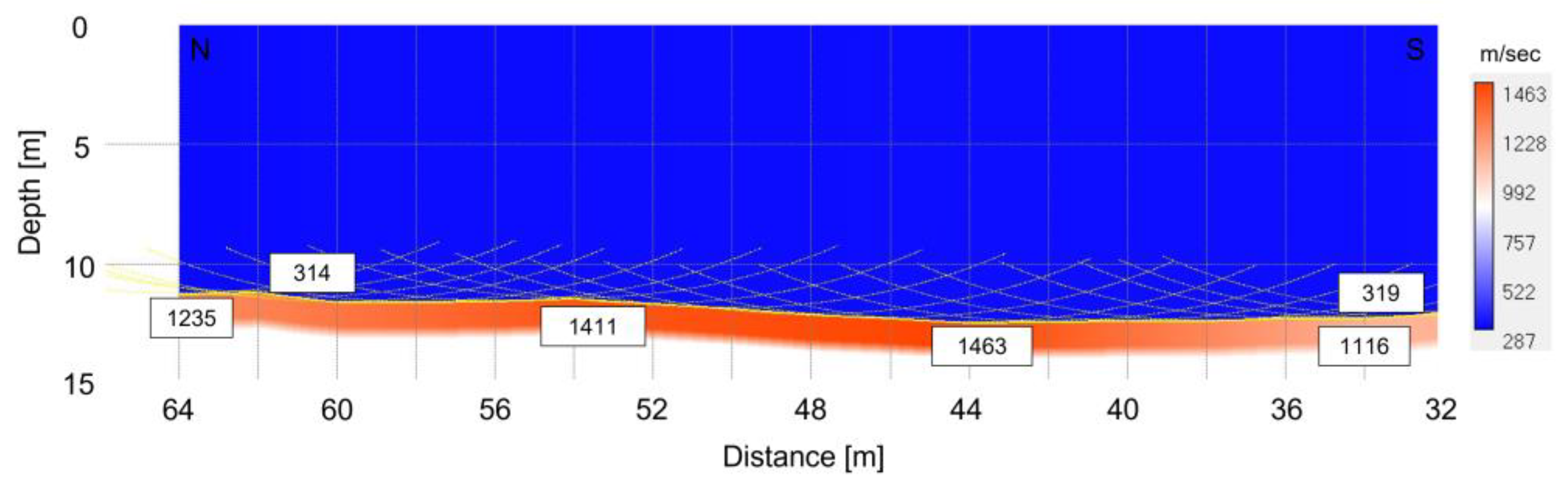
5.1. Seismic Reflection

The seismic reflection stack images show a strong reflector likely indicating the base of the landfill to be at a depth of 10 ± 2 m from the surface (Figure 5 and Figure 6).

5.2. Seismic Refraction

The data of Line 2 show seismic refraction events, and the base of the landfill is modeled to an approximate depth varying from 11 to 12 ± 1 m (Figure 7). Unfortunately, from the data of Line 1, it is impossible to estimate the landfill base because no refractions were found.

5.3. SW

According to the two seismic lines acquired, the passive SW results indicate a landfill’s thickness to be about 10 m (Figure 8, Figure 9, Figure 10 and Figure 11).

5.4. HVSR

The resonance frequency was estimated using the spectral ratio of the average horizontal components to the vertical component (HVSR). Twenty-four measurements were analyzed and interpreted (Figure 12). The peak frequencies varied between ~3.2 and ~10 Hz. Several measurements did not indicate any peak frequency.

6. Discussion

6.1. Thickness from HVSR Measurements

Due to the nature of the waste deposits, the landfill may exhibit lateral variations. However, we used Equation (1) to evaluate thickness from the HVSR measurements. According to the seismic reflection, seismic refraction, and SW results, the landfill thickness is roughly 10 m. Therefore, we calculated the average shear wave velocity (Vs) of the topmost ~10 m (Figure 13) and evaluated the landfill thickness for each HVSR sample. According to the peak frequency picked, and velocity of ~130 m/s, the thickness varies between ~4.8 and 11.2 m (Figure 14).

6.2. Uncertainties of the Different Methods

The vs. profiles from all methods vary by as much as ~30% (Figure 13), yielding Vs10 values that are within 25%. Some studies had comparable uncertain results [34,40,41], and others had lower values [42].
Each HVSR result has its own standard deviation (STD) for the fundamental frequency (f0). This STD can reach 1 Hz but is usually less than 0.5 Hz. According to Equation (1), this STD can be expressed as an approximately 25% difference in landfill thickness. These findings are similar to previous studies [43].
More than 90% of the HVSR results of Line 3 are very comparable. Unfortunately, this cannot be said about the results in Line 4, which indicates significant variance. The reason for such variance may be the limestone rocks at the north-west side, which are probably less deep and with steeper slopes than other parts of the landfill. This can also explain the higher values of f0, which indicates a lower boundary.
The seismic reflection ±2 m uncertainty yield from the resolution of the results. Both show a clear boundary around the same depth at the overlapping area.

6.3. Comparing All Results

Putting all the data together indicates that all methods converge to similar results (Figure 14). The seismic reflection result of the shorter seismic array (line 1) is very comparable to the SW results (line 3) (Figure 14). The HVSR results of this section are within the standard deviation of both the seismic reflection and SW results.
For the second segment, Lines 2 and 4 (Figure 14, lower panel), the seismic refraction result is similar to the SW results. The seismic refraction results fall within the lower STD boundary of the seismic reflection. The HVSR results of this section show a thinner thickness of the landfill layer.
It is important to note that due to the significant low Vs, the uncertainty of the HVSR results is considerably higher as compared to all other methods.

7. Conclusions

  • This study demonstrates the advantages of integrating information from five seismic approaches to estimate landfill thickness and constrain its content via its average shear velocity.
  • The results of all methods correlate comparably well with each other. Although the uncertainty of the HVSR results is more significant, the results are still within the uncertainty of the other methods.
  • By combining several geophysical methods, which are non-destructive, environmentally friendly, and relatively low-cost, the reliability of the results may increase and yield a more accurate solution.
  • All these methods can be jointly interpreted to assess uncertainties better and allow an efficient solution for environmental or engineering purposes.

Author Contributions

Conceptualization, Y.D. and A.A.; methodology, Y.D.; investigation, Y.D. and A.A.; writing—original draft preparation, Y.D. and A.A.; writing—review and editing, Y.D.; visualization, Y.D.; project administration, Y.D.; All authors have read and agreed to the published version of the manuscript.

Funding

This research received no external funding.

Data Availability Statement

Data are available on request due to privacy.

Acknowledgments

We would like to thank John K. Hall for his help with the manuscript. Moreover, our thanks go to Pavel Sinicin for his contribution to data processing.

Conflicts of Interest

The authors declare no conflict of interest.

References

  1. Cardarelli, E.; Bernabini, M. Two case studies of the determination of parameters of urban waste dumps. J. Appl. Geophys. 1997, 36, 167–174. [Google Scholar] [CrossRef]
  2. Lanz, E.; Maurer, H.; Green, A.G. Refraction tomography over a buried waste disposal site. Geophysics 1998, 63, 1414–1433. [Google Scholar] [CrossRef]
  3. Cardarelli, E.; Cercato, M.; Cerreto, A.; Di Filippo, G. Electrical resistivity and seismic refraction tomography to detect buried cavities. Geophys. Prospect. 2010, 58, 685–695. [Google Scholar] [CrossRef]
  4. Margiotta, S.; Negri, S.; Parise, M.; Quarta, T.A.M. Karst geosites at risk of collapse: The sinkholes at Nociglia (Apulia, SE Italy). Environ. Earth Sci. 2016, 75, 8. [Google Scholar] [CrossRef]
  5. Sunkpal, D.T.; Ankamah, A.T.; Tuoyang, M.K.; Ankah, M.L.Y. Geophysical investigation of groundwater potential zones, and modeling of subsurface materials using seismic refraction surveys. Model. Earth Syst. Environ. 2022, 8, 4389–4400. [Google Scholar] [CrossRef]
  6. Granda, A.; Cambero, J. The Use of Geophysical Techniques for the Detection and Characterization of Landfill in Areas of Urban Development; European Association of Geoscientists & Engineers: Utrecht, The Netherlands, 1998; pp. 111–114. [Google Scholar] [CrossRef]
  7. Abidin, M.H.Z.; Saad, R.; Ahmad, F.; Wijeyesekera, D.C.; Baharuddin, M.F.T. Seismic refraction investigation on near surface landslides at the Kundasang area in Sabah, Malaysia. Procedia Eng. 2012, 50, 516–531. [Google Scholar]
  8. Carpenter, P.J.; Reddy, K.R.; Thompson, M.D. Seismic imaging of a leachate-recirculation landfill: Spatial changes in dynamic properties of municipal solid waste. J. Hazard. Toxic Radioact. Waste 2013, 17, 331–341. [Google Scholar] [CrossRef]
  9. Konstantaki, L.A.; Ghose, R.; Draganov, D.; Diaferia, G.; Heimovaara, T. Characterization of a heterogeneous landfill using seismic and electrical resistivity data. Geophysics 2015, 80, EN13–EN25. [Google Scholar] [CrossRef] [Green Version]
  10. Dumont, G.; Robert, T.; Marck, N.; Nguyen, F. Assessment of multiple geophysical techniques for the characterization of municipal waste deposit sites. J. Appl. Geophys. 2017, 145, 74–83. [Google Scholar] [CrossRef]
  11. Ohori, M.; Nobata, A.; Wakamatsu, K. A comparison of ESAC and FK methods of estimating phase velocity using arbitrarily shaped microtremor arrays. Bull. Seismol. Soc. Am. 2002, 92, 2323–2332. [Google Scholar] [CrossRef]
  12. Okada, H. The Microtremor Survey Method, Geophysical Monograph Series Number 12; Society of Exploration Geophysicists: Tulsa, OK, USA, 2003; 135p. [Google Scholar]
  13. Park, C.B.; Miller, R.D.; Xia, J. Multichannel analysis of surface waves. Geophysics 1999, 64, 800–808. [Google Scholar] [CrossRef] [Green Version]
  14. Louie, J.N. Faster, Better: Shear-Wave Velocity to 100 Meters Depth from Refraction Microtremor Arrays. Bull. Seism. Soc. Am. 2001, 91, 347–364. [Google Scholar] [CrossRef]
  15. Castellaro, S.; Mulargia, F. VS30 estimates using constrained H/V measurements. Bull. Seismol. Soc. Am. 2009, 99, 761–773. [Google Scholar] [CrossRef]
  16. Yong, A.; Martin, A.; Stokoe, K.; Diehl, J. ARRA-Funded VS30 Measurements Using Multi-Technique Approach at Strong-Motion Stations in California Central-Eastern United States; U.S. Geological Survey Open-File Report 2013; US Department of the Interior, US Geological Survey: Washington, DC, USA, 2013; 60p. Available online: https://pubs.usgs.gov/of/2013/1102/ (accessed on 18 July 2022).
  17. Molnar, S.; Ventura, C.E.; Boroschek, R.; Archila, M. Site characterization at Chilean strong-motion stations: Comparison of downhole and microtremor shear-wave velocity methods. Soil Dyn. Earthq. Eng. 2015, 79, 22–35. [Google Scholar] [CrossRef]
  18. Moon, S.-W.; Subramaniam, P.; Zhang, Y.; Vinoth, G.; Ku, T. Bedrock depth evaluation using microtremor measurement: Empirical guidelines at weathered granite formation in Singapore. J. Appl. Geophys. 2019, 171, 103866. [Google Scholar] [CrossRef]
  19. Molnar, S.; Assaf, J.; Sirohey, A.; Adhikari, S.R. Overview of local site effects and seismic microzonation mapping in Metropolitan Vancouver, British Columbia, Canada. Eng. Geol. 2020, 270, 105568. [Google Scholar] [CrossRef]
  20. El-Raouf, A.A.; Iqbal, I.; Meister, J.; Abdelrahman, K.; Alzahrani, H.; Badran, O.M. Earthflow reactivation assessment by multichannel analysis of surface waves and electrical resistivity tomography: A case study. Open Geosci. 2021, 13, 1328–1344. [Google Scholar] [CrossRef]
  21. Wróbel, M.; Stan-Kłeczek, I.; Marciniak, A.; Majdański, M.; Kowalczyk, S.; Nawrot, A.; Cader, J. Integrated Geophysical Imaging and Remote Sensing for Enhancing Geological Interpretation of Landslides with Uncertainty Estimation—A Case Study from Cisiec, Poland. Remote Sens. 2022, 15, 238. [Google Scholar] [CrossRef]
  22. Bard, P.Y.; Irikura, K.; Kudo, K.; Okada, H.; Sasatani, T. Microtremor measurement: A tool for site effect estimation? In The Effects of Surface Geology on Seismic Motion; Taylor & Francis Group: Boca Raton, FL, USA, 1998. [Google Scholar]
  23. Mucciarelli, M.; Gallipoli, M.R. A critical review of 10 years of microtremor HVSR technique. Boll. Geofis. Teor. Appl. 2001, 42, 255–266. [Google Scholar]
  24. Arai, H.; Tokimatsu, K. S-wave velocity profiling by inversion of microtremor H/V spectrum. Bull. Seismol. Soc. Am. 2004, 94, 53–63. [Google Scholar] [CrossRef]
  25. Guillier, B.; Chatelain, J.-L.; Bonnefoy-Claudet, S.; Haghshenas, E. Use of ambient noise: From spectral amplitude variability to H/V stability. J. Earthq. Eng. 2007, 11, 925–942. [Google Scholar] [CrossRef]
  26. Felipe, L.; Montalva, G.; Ramírez, P. A preliminary study of seismic microzonation of Concepción based on microtremors, geology and damages patterns. Obras Proy. 2012, 11, 40–46. [Google Scholar]
  27. Hassani, B.; Yong, A.; Atkinson, G.M.; Feng, T.; Meng, L. Comparison of site dominant frequency from earthquake and microseismic data in California. Bull. Seismol. Soc. Am. 2019, 109, 1034–1040. [Google Scholar] [CrossRef]
  28. Sameer, L.; Molnar, S.; Palmer, S. Multi-method site characterization to verify the hard rock (Site Class A) assumption at 25 seismograph stations across Eastern Canada. Earthq. Spectra 2021, 37 (Suppl. 1), 1487–1515. [Google Scholar]
  29. Pastén, C.; Peña, G.; Comte, D.; Díaz, L.; Burgos, J.; Rietbrock, A. On the Use of the H/V Spectral Ratio Method to Estimate the Fundamental Frequency of Tailings Dams. J. Earthq. Eng. 2023, 27, 1649–1664. [Google Scholar] [CrossRef]
  30. Gosar, A.; Lenart, A. Mapping the thickness of sediments in the Ljubljana Moor basin (Slovenia) using microtremors. Bull. Earthq. Eng. 2009, 8, 501–518. [Google Scholar] [CrossRef]
  31. Parolai, S.; Bormann, P.; Milkereit, C. New relationships between Vs, thickness of sediments, and resonance frequency calculated by the H/V ratio of seismic noise for the cologne area (Germany). Bull. Seismol. Soc. Am. 2002, 92, 2521–2527. [Google Scholar] [CrossRef] [Green Version]
  32. Dal Moro, G. Surface Wave Analysis for Near Surface Applications; Elsevier: Amsterdam, The Netherlands, 2014. [Google Scholar]
  33. Foti, S.; Lai, C.G.; Rix, G.J.; Strobbia, C. Surface Wave Methods for Near-Surface Site Characterization; CRC Press: Boca Raton, FL, USA, 2014. [Google Scholar]
  34. Darvasi, Y. Shear-wave velocity measurements and their uncertainties at six industrial sites. Earthq. Spectra 2021, 37, 2223–2246. [Google Scholar] [CrossRef]
  35. Nogoshi, M.; Igarashi, T. On the amplitude characteristics of microtremor (part 2). J. Seismol. Soc. Jpn. 1971, 24, 26–40. [Google Scholar]
  36. Nakamura, Y. Method for Dynamic Characteristics Estimation of Subsurface Using Microtremor on the Ground Surface, Quarterly Report of RTRI (Railway Technical Research Institute) (Japan); Taylor & Francis: Boca Raton, FL, USA, 1989; Volume 30, pp. 25–33. [Google Scholar]
  37. Lermo, J.; Chávez-García, F.J. Site effect evaluation using spectral ratios with only one station. Bull. Seismol. Soc. Am. 1993, 83, 1574–1594. [Google Scholar] [CrossRef]
  38. Wathelet, M.; Chatelain, J.L.; Cornou, C.; Di Giulio, G.; Guillier, B.; Ohrnberger, M.; Savvaidis, A. Geopsy: A user-friendly open-source tool set for ambient vibration processing. Seismol. Res. Lett. 2020, 91, 1878–1889. [Google Scholar] [CrossRef]
  39. Dal Moro, G.; Pipan, M.; Gabrielli, P. Rayleigh wave dispersion curve inversion via genetic algorithms and marginal posterior probability density estimation. J. Appl. Geophys. 2007, 61, 39–55. [Google Scholar] [CrossRef]
  40. Cox, B.R.; Wood, C.M. Surface wave benchmarking exercise: Methodologies, results, and uncertainties. In Proceedings of the Geo-Risk 2011: Risk Assessment and Management, Atlanta, GA, USA, 26–28 June 2011; pp. 845–852. [Google Scholar]
  41. Kamai, R.; Darvasi, Y.; Peleg, Y.; Yagoda-Biran, G. Measurement and interpretation uncertainty in site response of nine seismic network stations in Israel. Seismol. Res. Lett. 2018, 89, 1796–1806. [Google Scholar] [CrossRef]
  42. Alan, Y.; Antony, M.; John, B. Precision of VS30 values derived from noninvasive surface wave methods at 31 sites in California. Soil Dyn. Earthq. Eng. 2019, 127, 105802. [Google Scholar] [CrossRef]
  43. Bignardi, S. The uncertainty of estimating the thickness of soft sediments with the HVSR method: A computational point of view on weak lateral variations. J. Appl. Geophys. 2017, 145, 28–38. [Google Scholar] [CrossRef]
Figure 1. Location map.
Geotechnics 03 00040 g001
Figure 2. Geological map.
Geotechnics 03 00040 g002
Figure 3. Aerial photo of the landfill area and its geological units (November 2021).
Geotechnics 03 00040 g003
Figure 4. Data acquisition.
Geotechnics 03 00040 g004
Figure 5. Seismic reflection Line 1 results. The upper figure shows the processed seismic section. The lower figure shows the same seismic section with a yellow marker indicating the estimated landfill base.
Geotechnics 03 00040 g005
Figure 6. Seismic reflection Line 2 results. The upper figure shows the processed seismic section. The lower figure shows the same seismic section with a yellow marker indicating the estimated landfill base.
Geotechnics 03 00040 g006
Figure 7. Seismic refraction Line 2 results.
Geotechnics 03 00040 g007
Figure 8. ESAC Line 4 results: Left figure: processed dispersion image. Pink dots—the analyst picked points. Blue line—the best fit for the dots. Dashed line—the marginal posterior probability density (MPPD) [39] defined as the mean shear wave profile. Right figure: shear wave velocity model. Blue line—the best-fit model. Dashed red line—the marginal posterior probability density (MPPD) [39], defined as the mean shear wave profile. Light green area—the constraints of the model.
Geotechnics 03 00040 g008
Figure 9. ReMi Line 4 results: Left figure: processed dispersion image. Pink dots—the analyst picked points. Blue line—the best fit for the dots. Dashed line—the marginal posterior probability density (MPPD) [39] defined as the mean shear wave profile. Right figure: shear wave velocity model. Blue line—the best-fit model. Dashed red line—the marginal posterior probability density (MPPD) [39], defined as the mean shear wave profile. Light green area—the constraints of the model.
Geotechnics 03 00040 g009
Figure 10. ESAC Line 3 results: Left figure: processed dispersion image. Pink dots—the analyst picked points. Blue line—the best fit for the dots. Dashed line—the marginal posterior probability density (MPPD) [39] defined as the mean shear wave profile. Right figure: shear wave velocity model. Blue line—the best-fit model. Dashed red line—the marginal posterior probability density (MPPD) [39], defined as the mean shear wave profile. Light green area—the constraints of the model.
Geotechnics 03 00040 g010
Figure 11. ReMi Line 3 results: Left figure: processed dispersion image. Pink dots—the analyst picked points. Blue line—the best fit for the dots. Dashed line—the marginal posterior probability density (MPPD) [39] defined as the mean shear wave profile. Right figure: shear wave velocity model. Blue line—the best-fit model. Dashed red line—the marginal posterior probability density (MPPD) [39], defined as the mean shear wave profile. Light green area—the constraints of the model.
Geotechnics 03 00040 g011
Figure 12. HVSR results of Lines 3 (upper figure) and 4 (lower figure).
Geotechnics 03 00040 g012
Figure 13. All SW results with the average velocity of the topmost ~10 (m).
Geotechnics 03 00040 g013
Figure 14. Comparison of all the geophysical methods.
Geotechnics 03 00040 g014
Table 1. Acquisition parameters.
MethodLine NumberSourceStackingSampling Interval (ms)Record LengthNumber of SensorsGeophone Intervals (m)Length of the Line (m)
Seismic reflection and refraction18 kg sledgehammer30.125148147
2294
ReMi and ESAC3------420–45 (min)124.549
47.581
HVSR---------115–60 (min)24------
Disclaimer/Publisher’s Note: The statements, opinions and data contained in all publications are solely those of the individual author(s) and contributor(s) and not of MDPI and/or the editor(s). MDPI and/or the editor(s) disclaim responsibility for any injury to people or property resulting from any ideas, methods, instructions or products referred to in the content.

