Abstract
Temperature differences between the surrounding ground and the tunnel lining will cause a variation of the tunnel lining forces. The hyperstatic reaction method (HRM) could be efficiently and simply used to investigate the impact of thermal load on tunnel linings. First, the steady state numerical solution is derived for a shallow circular tunnel to estimate the internal forces and displacements of tunnel lining caused by thermal load. The effective strain coefficient βTl is deduced to calculate the thermal stresses in tunnel lining. Secondly, the influence of the temperature difference on the internal forces of tunnel lining is investigated using the HRM method considering different lining elastic modulus, lining thickness and ground coefficient of thermal expansion. Lastly, the impact of fires which will be able to modify the elastic modulus of tunnel lining is investigated, which makes it possible to predict the damage of tunnel lining caused by fires.
1. Introduction
Tunnels have been extensively used for transportation, such as rail traffic, road and water; however, less attention is focused on the thermal stresses of tunnel lining caused by temperature differences. The temperatures inside the tunnel and/or in the surrounding ground are different in practice. The reasons which will cause a temperature change in tunnel lining have been presented by several studies:
- (1)
- Seasonal changes in ambient temperature: Luo et al. [1] have shown that the temperature of lining varies with the seasonal changes. For instance in their study, the temperature variation was between −1.8 °C in winter and 13.2 °C in summer.
- (2)
- Heating from the trucks, trains or passage of cars. Nicholson et al. [2] carried out an assessment of the available heat energy inside tunnels. They found that train heat emitted from the brakes, motors and air conditioning systems, could be able to warm the surrounding ground and the air.
- (3)
- Geothermal issues: Shallow geothermal energy is available all over the world (below 10 m to 400 m under the ground) [2]. The underground geotechnical structures, such as tunnel linings, have large structure-ground interfaces and can easily be converted as heat-exchangers [3,4,5,6]. Therefore, the temperature of lining may also change because of geothermal energy.
- (4)
- Fires: Emergency situations such as fires could be able to cause the temperature change in tunnels [7]. It was investigated by Maraveas and Vrakas [8] that a fire occurring in tunnel induces a rapid rise of the air temperature, to more than 1000 °C, within a few minutes. This rapid change of temperature results in an explosive concrete spalling of the tunnel lining [9], which not only brings about casualties and property loss, but also causes a prolonged disruption of operations.
Temperature change will give rise to a variation of internal forces in the tunnel lining. The thermal stresses represent the stresses caused by temperature change, which usually causes cracking and damage to the tunnel lining and surrounding ground. If the thermal stress is large enough, it may become a major factor causing the damage of structures. Many tunnels suffer from cracking damage due to thermal loading, such as the Channel Tunnel fire, which resulted in considerable damage over 480 m in France in 1996, or the Mont Blanc tunnel fire in 1999 where the tunnel roof was damaged. Clearly, temperature change has an impact on the internal forces of tunnel lining; however, a few research works could be found that investigated the stresses and displacements of tunnels caused by a thermal loading. For example, Barla and Di Donna [10] showed how thermo-mechanical analyses were used to design the tunnels by investigating the possibility of the thermal activation of tunnel linings. Luo et al. [1] analyzed the internal forces of tunnel lining under the ambient temperature changing in one year by monitoring strain on a lining tunnel in the Shaanxi Province. Despite this, one could not find a simplified way to evaluate the thermal stress of a circular tunnel, which means that there is no one efficient way to evaluate the impact of temperature change on the behavior of a circular tunnel lining. Therefore, it is required to find an efficient and rigorous calculation procedure to provide an appropriate design of a circular tunnel lining while considering the influence of temperature change.
The HRM method is a very effective way to estimate the tunnel lining forces (bending moments and normal forces) and displacements of tunnels. This method was proposed and developed [11,12] to study the behavior of circular tunnel linings under mechanical loading conditions. It could be able to provide the same results as the numerical ones, but with higher computational efficiency [11].
This paper starts with an introduction to the HRM method, including the ground-structure interaction and the loads applied to the tunnel lining. An improvement of this method is presented to show how to estimate the thermal stresses caused by temperature change. The effect of temperature change which causes the change of soil parameters and behavior is often not considered for simplicity purpose. A comparison with the results of Luo et al. is then given, which verifies the present method. A parametric analysis is presented to study the effect of temperature change on the internal forces of circular tunnel lining using the present method. The following factors, such as the lining thickness, elastic modulus, and ground coefficient of thermal expansion, are considered. Lastly, the impact of a fire on the behavior of circular tunnel lining is presented. The conclusion is given that heating the lining generates compressive forces, whereas cooling the lining leads to tensile forces. The temperature change has a significant influence on the internal forces of circular tunnel lining, which should be considered while designing the circular tunnels. The proposed simplified method could be able to give a design reference for the tunnel facing the thermal impact.
2. HRM Method
The HRM method permits calculating the displacements and internal forces of lining in a fast and accurate way [13,14,15,16,17,18,19,20]. The tunnel lining in this bi-dimensional method is subdivided into a finite number of linear beam elements (Figure 1) which are connected by nodes. The ground-structure interaction is established through springs connected to the element nodes and the active loads (σv and σh in Figure 1). It should be noted that normal and shear springs are taken into consideration. The beam element is defined by its area A and inertial modulus J on the transversal section, the elastic modulus E of the lining, and the length of element Li. Figure 1 presents the calculation sketch of a circular tunnel lining considering the additional thermal loads caused by temperature change, in which σv and σh are the vertical and horizontal loads, respectively; σT is the additional thermal loads caused by the temperature change; ks and kn represent the shear and normal stiffness of springs, respectively; EA and EI mean normal and bending stiffness of lining, respectively; X and Y are the global Cartesian coordinates; t is the thickness of lining.
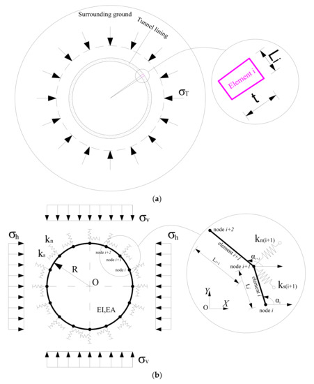
Figure 1.
Schematic diagram of circular tunnel lining in the analysis: (a) Calculation sketch of the additional thermal loads caused by temperature change; (b) Circular support structures in the HRM method.
As the ground-structure interaction is simulated by springs, the stresses of elements could be calculated by the unknown node displacements. The unknown displacement components [S] could be evaluated by the active loads and the global stiffness matrix [K] of the whole structure elements, which is shown as follows:
where F = [F1, F2, …, Fn]T are the external active loads, in which each sub-vector consists of three node external forces; S = [S1, S2, …, Sn]T are the unknown node displacement components, in which each sub-vector consists of the three node displacements.
The local stiffness matrix (i = 1, 2, 3…, n) of ith element under the global Cartesian reference system is used to assemble K, which is given as follows:
where n is the total number of elements; the terms , , and consist of sub-matrices of the local stiffness matrix .
is calculated by the local stiffness matrix under local Cartesian reference system as follows:
where is the transformation matrix, which is given as follows:
where represents the inclination angle of the ith element relative to the horizontal.
Since the structural stiffness of the elements will be changed due to the presence of springs, the corresponding elements along the diagonal of the global stiffness matrix should be modified as follows:
where and represent the stiffness of the shear and normal spring connected to node i, respectively.
After obtaining the displacement components [S] under the global reference system, a conversion of the node displacements to the local reference system can be achieved. The stress characteristics of nodes could be estimated through the local stiffness matrix.
2.1. Interaction of the Ground and Structure
The ground-structure interaction is described by a nonlinear relation between the reaction pressure and support displacement in the present analysis, which is introduced by Oreste [11] (see Figure 2), as follows:
where and represent respectively the initial ground stiffness and the maximum reaction pressure.
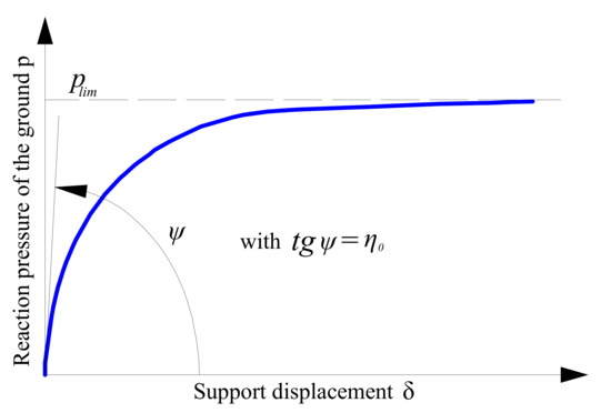
Figure 2.
Relationship of p and δ.
According to Oreste [11], the apparent stiffness of the ground could be determined by the ratio, which can be written as:
The initial normal stiffness can be calculated by:
where is the Poisson’s ratio of ground; is the tunnel radius; is Young’s modulus of ground; is a dimensionless factor.
The shear stiffness of springs is estimated by the normal stiffness as follows [21]:
is determined as follows:
The maximum shear reaction pressure is estimated by:
The shear stiffness and normal stiffness of each spring are given by:
2.2. Loads Applied to the Lining
The surrounding rock pressure and temperature stress are taken into consideration while investigating the stresses and displacements of tunnels. Those following assumptions are made: (1) temperature change in the lining is the same as the one in the surrounding ground; (2) the parameters of ground, such as , c, φ and are constant under the effect of temperature [22].
As temperature change is taken into consideration, the external loads consist of two parts in the analysis: (1) the additional thermal loads ( shown in Figure 1a) caused by temperature change; (2) the earth active loads ( and shown in Figure 1b) applied by the ground.
2.2.1. Active Loads
The active vertical load applied by ground is estimated according to the Terzaghi’s theory [23]:
where is the overburden thickness which is the vertical distance from the tunnel center to the ground surface; is the unit weight of ground. If is two times larger than the circular tunnel diameter, an effective depth should be taken into consideration as follows [23]:
where R is the tunnel radius; means the lateral earth pressure factor. Please note that if is lower than two times the tunnel external diameter, is set equal to two times of the tunnel external diameter.
The active horizontal load applied by the soil is calculated as follows:
2.2.2. Additional Thermal Loads
The temperature in surrounding ground and tunnels changes with time. The temperature change causes the thermal shrinkage or expansion of tunnel lining. Since the lining is suffered from the restraint of surrounding ground, the lining internal stresses will change with different temperature.
is assumed to be a uniform load (see in Figure 1a). The tunnel lining is assumed to be contacted with the ground without considering the effect of the temperature change. consists of the additional thermal load from the circular tunnel lining and the additional thermal load from the ground. The total thermal load is therefore calculated by:
It is given that the ground-structure contact is rigid and the ground is perfectly restrained by the tunnel lining, so that the potential soil strains caused by temperature change could be totally converted to additional thermal stresses. could then be expressed as follows:
in which is the radial restrained thermal strain of ground caused by temperature change, which is given as follows:
where is the temperature change; is the thermal expansion coefficient of the ground (/°C).
As only the outer surface of tunnel lining is constrained by the surrounding ground and the inner surface of tunnel lining is free, the lining strains induced by temperature change cannot be completely converted to additional tunnel lining thermal stresses. It is emphasized by Amatya et al. [24] that only the restrained thermal strains of the structure could be able to induce thermal stresses. Herein, an effective strain coefficient of tunnel lining is introduced to evaluate the , which represents the proportion of strain which could be able to convert into thermal stress. is therefore expressed as follows:
in which E is the Young’s modulus of the circular tunnel lining; is the radial thermal strain of the tunnel lining caused by temperature change, which is calculated by:
where is the thermal expansion coefficient of tunnel lining (/°C).
It could be found from Equation (25) that is the key point to calculate . However, no authors have proposed a formulation to evaluate . Since Luo et al. [1] investigated the lining forces under ambient temperature by monitoring the tunnel lining strain of a tunnel in the Shanxi Province (China), the value of β_Tl was determined by comparing the internal forces calculated by the present method to the ones of Luo et al. [1]. Table 1 gives the lining properties used in Luo et al. [1].

Table 1.
Lining properties used in the analysis.
The initial temperature of tunnel lining in Luo et al. [1] was equal to 12 °C. In the analysis, the Es is taken equal to 300 MPa; vs is 0.3; h is 40 m; K0 is 0.8; γ is 22 kN/m3; φ and c are respectively 20 degrees and 50 kPa. Table 2 shows the inner thermal forces of tunnel lining induced by temperature change from the in situ data [1] and the present method, in which the normal forces calculated by the present method correspond to with t/[(R − t/2)2]. It should be noticed that with t/[(R − t/2)2] is proposed by authors after extensive trial calculations. From Table 2, one can find that the results of the present method are in good agreement with ones of Luo et al. [1]. Since their error is less than 7%, with t/[(R − t/2)2] is taken into consideration. The positive direction of the lining forces (bending moment M, normal force N) considered in the analysis is shown in Figure 3.
Table 2.
Inner thermal forces of tunnel lining from Luo et al. [1] and the present method.

Figure 3.
Positive direction of the lining forces. θ: the angle between the element axis and the vertical axis of tunnel cross-section.
As Do et al. [12] investigated the impact of active loads applied by the ground on the behavior of a circular tunnel lining, herein, only the thermal loads are presented to show the effect of temperature change on the incremental internal forces of a circular tunnel lining.
The properties of the tunnel lining and ground from the Toulon tunnel in France [25] are adopted in the analysis, which are shown in Table 3.
Table 3.
Properties of the tunnel lining and ground.
3. Impact of ∆T on the Internal Forces of Tunnel Lining
Barla and Di Donna [10] found that the ground temperature varies between 8 °C and 16 °C at depths being higher than 5–8 m, but it remains constant when depth is over 50 m. In addition, it was found by Luo et al. [1] that the temperature change ∆T is about 15 °C. It is, therefore, assumed that a constant temperature equal to 20 °C and the tunnel lining is subjected to a ∆T varying from −15 °C to +15 °C in the analysis.
3.1. Only Considering
While the underground trains stopping at platforms, braking or accelerating, significant heat will be generated. It is assumed that there is no enough time to transmit the heat from tunnel lining to surrounding ground. Therefore, herein only the effect of on the internal forces of tunnel lining in investigated. is taken as 1.2 × 10⁻⁵ °C−1 and is 0 °C−1. The other properties shown in Table 3 are considered.
As the tunnel lining is restrained by ground (Figure 1a), the bending moment of tunnel lining caused by the temperature change is close to 0 when the temperature varies from −15 °C to +15 °C. Therefore, Figure 4 only gives the impact of ∆T on the normal forces and stress of tunnel lining. In addition, since it is assumed that the additional thermal loads apply uniformly to the circular tunnel lining (shown in Figure 1a), same stresses and normal forces of tunnel lining are obtained along the whole tunnel when the value of ∆T keeps constant. From Figure 4, one can find that heating the tunnel lining leads to compressive normal forces, whereas cooling the tunnel lining generates tensile normal forces, which is consistent with the conclusion given in Bourne-Webb et al. [26]. In addition, the greater the ∆T, the greater the internal forces of tunnel lining. For the same absolute value of ∆T, a heating load produces a similar response as that of a cooling load.

Figure 4.
Effect of ∆T on the internal forces of tunnel lining when only considering : (a) Normal force; (b) Stress of lining.
3.2. Considering and
This section gives the impact of the temperature change ∆T on the internal forces of tunnel lining when considering both and , which is shown in Figure 5. The is taken as 1.2 × 10⁻⁵ °C−1 and is 5 × 10⁻⁶ °C−1. Compared to the results of Figure 4, one can find that the absolute force values considering both and are higher than of the ones where only are considered.

Figure 5.
Effect of ∆T on the internal forces of tunnel lining when considering both and : (a) Normal force; (b) Stress of lining.
3.3. Impact of Other Factors on the Internal Forces of Tunnel Lining
The impact of other factors, such as the Young’s modulus E, thickness t of tunnel lining and the type of ground, on the internal forces of tunnel lining is presented, in which is set equal to 1.2 × 10⁻⁵ °C−1.
As mentioned in Section 3.1, the internal forces caused by a temperature change (from −15 °C to +15 °C) stay constant along the whole tunnel. Therefore, only the normal lining forces and stresses at the tunnel crown will be shown in the analysis.
3.3.1. Impact of Lining Thickness t
The impact of ∆T on the internal forces of tunnel lining for different t is herein investigated. The t varies from 0.3 m to 0.6 m.
Figure 6 presents the internal forces of tunnel lining for different ∆T and t. It could be found from Figure 6 that the absolute values of stresses decrease as the increase of t; however, the absolute values of normal forces increase as t increases. This is because the lining stress strongly depends on t and is calculated by the formula as follows:
in which M and N are respectively the bending moment and normal force of tunnel lining; I is the moment of inertia and y is taken as t/2 which also depend on t; A represents the cross-sectional area of the tunnel lining.

Figure 6.
Impact of ∆T on the internal forces of tunnel lining with different t: (a) Normal force; (b) Stress of lining
.
From Equation (27), one can find that the greater the ∆T, the greater the internal forces of lining. In addition, the thicker the lining, the smaller the stress value. Heating the lining generates compressive forces, whereas cooling the lining causes tensile forces.
3.3.2. Impact of Lining Elastic Modulus E
The impact of ∆T on the internal forces of tunnel lining considering different E is investigated herein, and shown in Figure 7. The E in the analysis varies from 20 GPa to 50 GPa. It is found from Figure 7 that the absolute values of the lining forces increase as E increases. This is because the bending and normal stiffness (EI and EA) of the tunnel lining depend on E, and the lining stiffness increases with the increase of E.

Figure 7.
Impact of ∆T on the internal forces of tunnel lining considering different E: (a) Normal force; (b) Stress of lining.
3.3.3. Impact of the Thermal Expansion Coefficient of the Ground
The depends on the ground type [27]. The effect of ∆T on the internal forces of tunnel lining is therefore shown in Figure 8 for different , in which changes from 3 to 7 × 10⁻⁶ °C−1. From Figure 8, it can be found that the maximum difference is less than 14.3%, when is 15 °C. The absolute values of lining internal forces increase as increases.

Figure 8.
Impact of ∆T on the internal forces of tunnel lining while considering different : (a) Normal force; (b) Stress of lining.
4. Impact of Fires on the Internal Forces of Tunnel Lining
The internal forces of lining structure are analyzed in this section supposing that the tunnel lining subjected to a severe fire. It was found that a loss of lining strength and stiffness [8,28] will be caused in the event of a fire, as the temperature of the tunnel lining rises rapidly in an instant. Many fire tests, e.g., the EUREKA fire test [7], were executed to determine the temperature development and the damage pattern of lining structure during a tunnel fire. It was found that the gas temperature at the tunnel ceiling rises to temperatures of over 800 °C after about 5 min [7], which results in concrete spalling of the lining. It is, therefore, important to investigate the behavior of tunnel lining at elevated temperatures.
In the following analysis, the impact of a fire on the relevant elastic modulus of tunnel lining is first introduced and then the influence of a fire on the lining behavior is investigated. To study a fire impact on the internal forces of tunnel lining, the temperature of lining structure is assumed to vary from 100 °C to 800 °C [29]. As the temperature in the tunnel lining rises rapidly in a very short time, it is assumed that the heat in tunnel lining generated by a fire could not be transmitted to the surrounding ground. The additional thermal load from ground is therefore neglected and only the additional thermal load from tunnel lining is taken into account in the following analysis. In addition, as Guo et al. [29] found that the coefficient of thermal expansion of tunnel lining is not sensitive to temperature; it is assumed that remains unchanged under different temperatures.
4.1. Impact of Fires on the Elastic Modulus E of Tunnel Lining
The tunnel lining structure is prefabricated by steel reinforced concrete. Many studies have reported that the high temperature will degrade the lining performance. For example, Aslani and Samali [27] proposed a constitutive model for high strength reinforced concrete subjected to fires by studying the impact of the elevated temperatures on the reinforced concrete behavior. The elasticity modulus of the reinforced concrete at elevated temperatures could be evaluated by this constitutive model which is expressed as follows:
where ET is the elastic modulus of tunnel lining at different temperatures, which is shown in Figure 9.

Figure 9.
Young’s modulus of tunnel lining with different temperatures expressed by Equation (28).
4.2. Impact of Fires on the Behavior of Tunnel Lining
The spontaneous development of a large amounts of heat will cause the damage of lining structures [7]. In addition, the fire tests found that the maximum temperature of tunnel lining occurs at the tunnel crown. Therefore, this section gives the impact of fires on the behavior of lining at the tunnel crown in terms of internal forces and radial displacements, which is shown in Figure 10. The other mechanical properties of ground and lining used in the analysis are presented in Table 3.

Figure 10.
Impact of the temperature on the behavior of tunnel lining at the tunnel crown considering different : (a) Bending moment of lining; (b) Normal force of lining; (c) Intrados stress of lining; (d) Extrados stress of lining; (e) Radial displacement of lining.
From Figure 10, one can find that the maximum stresses of tunnel lining appear when the temperature is approximately 400 °C for a fire event. Even though the tunnel lining is restrained by the surrounding ground, the lining bending moment caused by the temperature change should not be neglected while the temperature change is over 100 °C. The bending moments of tunnel lining caused by a fire decrease as the temperature increases. Figure 10b gives that the normal forces of tunnel lining increase first and reach a peak of 6.63 MN/m as the temperature is about 400 °C. On the contrary, those normal forces decrease as the temperature is more than 400 °C. This is because that the elastic modulus of tunnel lining decreases with the increase of the temperature. Therefore, the thermal-induced stresses will decrease as the temperature is over 400 °C, which are shown in Figure 10c,d. Since the absolute values of the bending moment are significantly less than the ones of the axial force, the extrados and intrados stresses of tunnel lining have the similar trend as the normal forces.
Figure 10e presents that the radial displacements of tunnel lining increase with the increase of the temperature, which explains why the lining forces of tunnel lining increase first and then decrease as the temperature increases. Consequently, the lining strain caused by the temperature change increases as the temperature increases.
It should be noted that the maximum normal force of tunnel lining is 7.75 MN/m without considering the earth active loads applied by the ground. If taking the earth active loads into account, the normal force of tunnel lining will be 8.10 MN/m corresponding to the temperature with 200 °C. It exceeds the maximum admissible value of tunnel lining, which leads to the lining collapse. The limit state of the linings should then be verified for designing such structures suffering from a thermal loading.
In addition, Kaundinya [7] found that the spalling of tunnel lining happens during the first five minutes from the beginning of a fire event. The ETK/ISO curve used to describe the relationship of temperature and time in the case of a fire [7] is presented in Figure 11. From this figure, one can find that the temperature exceeds 400 °C at the 5th minute. Hence, this paper could give a possible explanation fpr lining spalling in the case of a fire event from the lining structural point of view.
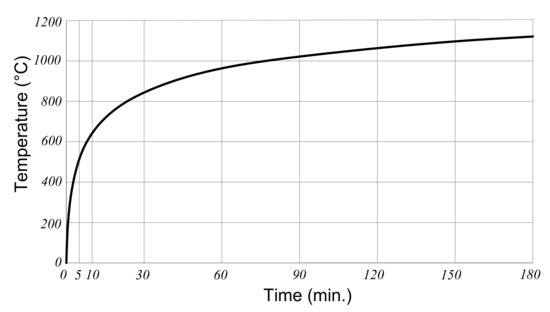
Figure 11.
ETK/ISO curve adopted to describe the relationship of temperature and time in the analysis.
It could be found that the fires have a significantly negative effect on the lining behavior. The first 5 min corresponding to the temperature exceeding 400 °C represents the worst time. Damage of the tunnel lining occurs if the tunnel lining has no protection and is on fire. Preventive measures need to be taken to protect the tunnel lining from fires. Some possible measures of the fire protection in tunnels have been summarized by Kaundinya [7]: (1) fire-proof panels installed on the outer side of the lining; (2) sprayed fire protection (e.g., fire-proof render); (3) novel concrete mixtures containing polypropylene fibers; (4) high strength concrete with an extremely tight texture. Maraveas and Vrakas [8] also proposed some prevention measures, such as compressive stress control, thermal barrier, choice of section type/shape, supplementary reinforcement, etc.
5. Conclusions
This manuscript presents an efficient way to evaluate the influence of temperature change on the behavior of tunnel lining using the HRM method. First, an effective lining strain coefficient determined by in situ results is introduced to calculate the effective thermal stresses of tunnel lining. Secondly, the impact of temperature change on the internal forces of tunnel lining considering different factors is investigated by means of the present method. Lastly, the impact of fires on the internal forces of tunnel lining is studied. Some conclusions are given:
- Heating the lining generates compressive forces, whereas cooling the lining leads to tensile forces;
- The stresses of tunnel lining decrease with the increase of lining thickness, whereas the absolute values of lining normal forces increase as the lining thickness increases;
- The absolute internal forces values of tunnel lining increase with the increase of the lining elastic modulus;
- The effect of the soil thermal expansion coefficient on the internal forces of tunnel lining could be neglected;
- The maximum force of tunnel lining appears when the temperature is about 400 °C for a fire event.
In summary, it is found by the present simplified method that the temperature change has a significant impact on the behavior of circular tunnel lining. The proposed simplified method is able to give a preliminary design of tunnel linings considering the thermal loading impact.
Author Contributions
D.D. (Dianchun Du): Conceptualization, Methodology, Validation, Writing—original draft, Writing—review & editing. D.D. (Daniel Dias): Conceptualization, Writing—review & editing, Supervision. N.-A.D.: Writing—review & editing. All authors have read and agreed to the published version of the manuscript.
Funding
This research is supported by the Natural Science Foundation of Jiangsu Province (Grant No. BK20210256), the National Natural Science Foundation of China (Grant No. 52108305), the Jiangsu Provincial Double-Innovation Doctor Program (Grant No. JSSCBS20210068) and, the Vietnam Ministry of Education and Training (Project No. B2020-MDA-15), which are gratefully acknowledged. Special thanks to the reviewers and editors for their comments and work.
Institutional Review Board Statement
Not applicable.
Informed Consent Statement
Not applicable.
Data Availability Statement
All data generated or used during the study appear in the submitted article.
Conflicts of Interest
The authors declare that there is no conflict of interest.
References
- Luo, Y.B.; Chen, J.X.; Qiao, X.; Wang, M.S. Mechanics state analysis of secondary lining concrete structure on tunnel based on temperature effect. China J. Highw. Transp. 2010, 23, 64–69. [Google Scholar]
- Nicholson, D.P.; Chen, Q.; Silva, M.; Winter, A.; Winterling, R. The design of thermal tunnel energy segments for Crossrail, UK. Proc. Inst. Civ. Eng. Eng. Sustain. 2014, 167, 118–134. [Google Scholar] [CrossRef] [Green Version]
- Brandl, H. Energy foundations and other thermo-active ground structures. Géotechnique 2006, 56, 81–122. [Google Scholar] [CrossRef]
- Franzius, J.N.; Pralle, N. Turning segmental tunnels into sources of renewable energy. Proc. Inst. Civ. Eng. 2011, 164, 35. [Google Scholar] [CrossRef]
- Barla, M.; Perino, A. Energy from geo-structures: A topic of growing interest. Environ. Geotech. 2015, 2, 3–7. [Google Scholar] [CrossRef] [Green Version]
- Barla, M.; Di Donna, A.; Insana, A. A novel real-scale experimental prototype of energy tunnel. Tunn. Undergr. Space Technol. 2019, 87, 1–14. [Google Scholar] [CrossRef]
- Kaundinya, I. Protection of road tunnel linings in cases of fire. In Proceedings of the FEHRL/FERSI/ECTRI Young Researchers Seminar, Brno, Czech Republic, 28–30 May 2007. [Google Scholar]
- Maraveas, C.; Vrakas, A.A. Design of concrete tunnel linings for fire safety. Struct. Eng. Int. 2014, 24, 319–329. [Google Scholar] [CrossRef] [Green Version]
- Zeiml, M.; Lackner, R.; Mang, H.A. Experimental insight into spalling behaviour of concrete tunnel linings under fire loading. Acta Geothech. 2008, 3, 295–308. [Google Scholar] [CrossRef]
- Barla, M.; Di Donna, A. Energy tunnels: Concept and design aspects. Undergr. Space 2018, 3, 268–276. [Google Scholar] [CrossRef]
- Oreste, P.P. A numerical approach to the hyperstatic reaction method for the dimensioning of tunnel supports. Tunn. Undergr. Space Technol. 2007, 22, 185–205. [Google Scholar] [CrossRef]
- Do, N.A.; Dias, D.; Oreste, P.; Djeran-Maigre, I. The behaviour of the segmental tunnel lining studied by the hyperstatic reaction method. Eur. J. Environ. Civ. Eng. 2013, 18, 489–510. [Google Scholar] [CrossRef]
- Du, D.C.; Dias, D.; Do, N.A.; Oreste, P.P. Hyperstatic Reaction Method for the Design of U-Shaped Tunnel Supports. Int. J. Geomech. 2018, 18, 1–12. [Google Scholar] [CrossRef]
- Du, D.C.; Dias, D.; Do, N.A. Designing U-shaped tunnel linings in stratified soils using the hyperstatic reaction method. Eur. J. Environ. Civ. Eng. 2018, 11, 1–18. [Google Scholar] [CrossRef]
- Du, D.C.; Dias, D.; Yang, X.L. Analysis of earth pressure for shallow tunnels in anisotropic and non-homogeneous soil. Comput. Geotech. 2018, 104, 226–236. [Google Scholar] [CrossRef]
- Guo, X.F.; Du, D.C.; Dias, D. Reliability analysis of tunnel lining considering soil spatial variability. Eng. Struct. 2019, 196, 109332. [Google Scholar] [CrossRef]
- Du, D.C.; Dias, D.; Do, N.A. Lining performance optimization of sub-rectangular tunnels using the Hyperstatic Reaction Method. Comput. Geotech. 2020, 117, 103279. [Google Scholar] [CrossRef]
- Du, D.C.; Dias, D.; Do, N.A.; Vo, T. U-shaped tunnel lining design using the Hyperstatic Reaction Method—Influence of the invert. Soils Found. 2020, 60, 592–607. [Google Scholar] [CrossRef]
- Du, D.C.; Dias, D.; Do, N.A. Effect of surcharge loading on horseshoe-shaped tunnels excavated in saturated soft rocks. J. Rock Mech. Geotech. Eng. 2020, 12, 1339–1346. [Google Scholar] [CrossRef]
- Sun, Q.Q.; Du, D.C.; Dias, D. An improved Hyperstatic Reaction Method for tunnels under seismic loading. Tunn. Undergr. Space Technol. 2021, 108, 103687. [Google Scholar] [CrossRef]
- Arnau, O.; Molins, C. Experimental and analytical study of the structural response of segmental tunnel supports based on an in situ loading test. Part 2: Numerical simulation. Tunn. Undergr. Space Technol. 2010, 26, 778–788. [Google Scholar] [CrossRef] [Green Version]
- Xi, B.P.; Zhao, Y.S. Experimental study of thermo-physico-mechanical property of drilling surrounding rock in granite under high temperature and high pressure. Chin. J. Rock Mech. Eng. 2010, 29, 1245–1253. [Google Scholar]
- Takano, Y.H. Guidelines for the design of shield tunnel lining. Tunn. Undergr. Space Technol. 2000, 15, 303–331. [Google Scholar]
- Amatya, B.; Soga, K.; Bourne-Webb, P.J.; Amis, T.; Laloui, L. Thermo-mechanical behaviour of energy piles. Géotechnique 2012, 62, 503–519. [Google Scholar] [CrossRef]
- Oreste, P.P.; Dias, D. Stabilisation of the excavation face in shallow tunnels using fibreglass dowels. Rock Mech. Rock Eng. 2012, 45, 499–517. [Google Scholar] [CrossRef]
- Bourne-Webb, P.J.; Bodas-Freitas, T.M.; Freitas-Assunção, R.M. Soil–pile thermal interactions in energy foundations. Géotechnique 2015, 66, 167–171. [Google Scholar] [CrossRef]
- Aslani, F.; Samali, B. Constitutive relationships for steel fibre reinforced concrete at elevated temperatures. Fire Technol. 2014, 50, 1249–1268. [Google Scholar] [CrossRef]
- Hertz, K.D. Limits of spalling of fire-exposed concrete. Fire Saf. J. 2003, 38, 103–116. [Google Scholar] [CrossRef]
- Guo, J.; Jiang, S.P.; Zhang, Z.Y. Fire thermal stress and its damage to subsea immersed tunnel. Procedia Eng. 2016, 166, 296–306. [Google Scholar] [CrossRef]
Publisher’s Note: MDPI stays neutral with regard to jurisdictional claims in published maps and institutional affiliations. |
© 2021 by the authors. Licensee MDPI, Basel, Switzerland. This article is an open access article distributed under the terms and conditions of the Creative Commons Attribution (CC BY) license (https://creativecommons.org/licenses/by/4.0/).