Article

Solution-Processed Bilayered ZnO Electron Transport Layer for Efficient Inverted Non-Fullerene Organic Solar Cells

by
Walia Binte Tarique
1,*,
Md Habibur Rahaman
2,
Shahriyar Safat Dipta
1,
Ashraful Hossain Howlader
1 and
Ashraf Uddin
1,*
1
School of Photovoltaic and Renewable Energy Engineering, University of New South Wales, Sydney, NSW 2052, Australia
2
School of Chemistry, University of New South Wales, Sydney, NSW 2052, Australia
*
Authors to whom correspondence should be addressed.
Nanomanufacturing 2024, 4(2), 81-98; https://doi.org/10.3390/nanomanufacturing4020006
Submission received: 7 December 2023 / Revised: 7 February 2024 / Accepted: 8 March 2024 / Published: 1 April 2024

Abstract

:
Organic solar cells (OSCs) are becoming increasingly popular in the scientific community because of their many desirable properties. These features include solution processability, low weight, low cost, and the ability to process on a wide scale using roll-to-roll technology. Enhancing the efficiency of photovoltaic systems, particularly high-performance OSCs, requires study into not only material design but also interface engineering. This study demonstrated that two different types of OSCs based on the PTB7-Th:IEICO-4F and PM6:Y6 active layers use a ZnO bilayer electron transport layer (ETL). The ZnO bilayer ETL comprises a ZnO nanoparticle (ZnO NP) and a ZnO layer created from a sol-gel. The effect of incorporating ZnO NPs into the electron transport layer (ETL) was studied; in particular, the effects on the electrical, optical, and morphological properties of the initial ZnO ETL were analyzed. The ability of ZnO films to carry charges is improved by the addition of ZnO nanoparticles (NPs), which increase their conductivity. The bilayer structure had better crystallinity and a smoother film surface than the single-layer sol-gel ZnO ETL. This led to a consistent and strong interfacial connection between the photoactive layer and the electron transport layer (ETL). Therefore, inverted organic solar cells (OSCs) with PTB7-Th:IEICO-4F and PM6:Y6 as photoactive layers exhibit improved power conversion efficiency and other photovoltaic properties when using the bilayer technique.

1. Introduction

Solution-processed photovoltaic systems are characterized by their cost-effectiveness and suitability for large-scale manufacturing, making them particularly well suited for novel applications in the area of photovoltaics [1,2]. Consequently, considerable research efforts have been focused on the study of solution-based systems, both organic and inorganic in composition. The systems under consideration encompass an extensive variety of materials, including polymers [3,4,5,6], small molecules [7,8,9], quantum dots [10,11], and perovskite photovoltaics [12,13,14,15]. Typically, conventional organic solar cells (OSCs) consist of various fundamental components, including a transparent conductive anode, such as indium tin oxide (ITO), an anode buffer layer composed of acidic poly(3,4-ethyl enedioxythiophene)/poly(styrenesulfonate) (PEDOT: PSS), a low work function metal cathode, such as aluminum (Al) or calcium (Ca), and a photoactive layer comprising a blended bulk heterojunction (BHJ) conjugated polymer and fullerene derivative. The aforementioned constituents are arranged in a configuration like that of a sandwich, wherein the photoactive layer is positioned between the anode and cathode electrodes. Nevertheless, the PEDOT:PSS layer’s high acidity, corrosive properties, and hygroscopic nature pose a limitation for ITO. In addition, organic solar cells (OSCs) are subject to degradation and inadequate stability as a result of the low work function of the metallic cathode, which is prone to oxidation when exposed to oxygen and water vapor [16,17]. To tackle this issue, scholars designed inverted device configurations that modify the direction of the hole and electron transport. The accomplishment of this goal entails the usage of a metal possessing a high work function as the anode situated on the top portion of the device, while utilizing indium tin oxide (ITO) as the cathode positioned on the bottom side [18,19].
In order to improve electron extraction, several different metal oxides have been studied. These include zinc oxide (ZnO) [20,21,22], titanium oxide (TiOx) [23], cesium carbonate (Cs2CO3) [24,25], and others. Metal oxide coatings may be used to modify ITO’s work function. Both thermal evaporation and a solution-based technique are capable of achieving this goal. For large areas, such as those used in roll-to-roll printing, solution-processed metal oxides are the material of choice [26]. Zinc oxide (ZnO) garnered a lot of interest due to its potential use as an electron transport layer (ETL). These features stem from the material’s exceptional electron mobility, environmental stability, transmittance, and the ease with which different nanostructures may be generated by means of solution methods. Because of its low cost and great flexibility, ZnO is often considered an ideal material for the roll-to-roll manufacturing process, especially when applied on flexible substrates [27,28]. Various methods such as sol-gel (SG) [21], hydrothermal [29], electrodeposition [30], atomic layer deposition [28], and so on, have been explored for the preparation of various nanostructures of ZnO.
Crystallinity of zinc oxide (ZnO) synthesized via sol-gel processing at low temperatures is poor. It has been discovered that the observed decrease in crystallinity leads to a larger level of trap dispersion inside the ETL, which has a deleterious effect on the device’s overall performance [20]. On the other hand, research from the past has shown that prolonged annealing of the ZnO film at high temperatures might increase its porosity. It is possible, then, that voids will form between the ZnO film and the active layer. It is vital to realize that these voids contain the ability to detrimentally disrupt the effectiveness of electron extraction [31]. Therefore, it is crucial to design a systematic method for adjusting the ETL of ZnO to address the porosity problem while retaining the absorption properties of the active layer. The interface engineering has been conducted by incorporating additional layers, including fullerene derivatives, conjugated polyelectrolytes, semiconductor NPs, and metal oxides, between the ZnO and the active layer [32,33,34]. Prior research has indicated that the use of insertion layers, such as water-soluble conjugated polymer PFN-Br and PEIE, can successfully decrease the surface defect density of the ZnO electron transport layer (ETL) and enhance the interfacial contact between the active layer and the ZnO NP ETL. This leads to an enhancement in the mobilities of charge carriers and a decrease in the leakage current of the devices [35,36]. In their study, Cheng et al. discovered that the binding energy difference between polymer donors and NFAs was increased by modifying the surface of zinc oxide with potassium, as compared to untreated zinc oxide. The outcome was a vertical phase separation that favored the acceptor near the cathode and the donor near the anode. This led to significantly improved charge extraction efficiency [37]. Supplementary Table S1 presents the photovoltaic parameters of organic solar cells utilizing a ZnO-based electron transport layer (ETL). According to Supplementary Table S1, using ETL with modifications results in better performance than using a bare ZnO-based cell in terms of charge recombination loss reduction, charge collection probability enhancement, and exciton quenching inhibition in organic solar cells (OSCs). All J-V characteristics of the modified ETL-based device were considerably greater than those of the control device, leading to an increase in efficiency along with other photovoltaic measurements [10,32,33,34,37,38,39,40,41,42]. In another investigation, Pan et al. were able to achieve a power conversion efficiency (PCE) of 14.29% for flexible organic solar cells. This was accomplished by employing sol-gel ZnO and ZnO NP bilayer ETLs. The utilization of the sol–gel ZnO and ZnO NP bilayer electron transport layer (ETL) has resulted in decreased porosity and enhanced interface charge collection [43].
To improve the performance of organic solar cells with the use of a non-fullerene acceptor, this research modified the ZnO ETL. ZnO nanoparticles (NPs) were integrated with a sol-gel-generated ZnO layer to create the ETL, and the resulting structure had a bilayer architecture. The adoption of a bilayer ZnO structure, which modifies the electrical and optical properties of the material, exemplifies the effectiveness of the method. Moreover, organic solar cells (OSCs) with two distinct active layers, namely PTB7-Th:IEICO-4F and PM6:Y6, exhibit remarkable photovoltaic performance. The power conversion efficiency (PCE) was 10.2% when devices with PTB7-Th:IEICO-4F as the active layer were combined with a bilayer ZnO NP/ZnO electron transport layer, compared to 9.18% when using a single layer of ZnO NPs. A comparable efficiency boost, from 13.95% to 14.6%, was seen using a PM6:Y6 active layer in a ZnO NP/ZnO ETL bilayer arrangement. Significant improvements in other photovoltaic characteristics may be attributed to the higher PCE seen in OSCs with an inverted configuration.

2. Experimental Section

2.1. Materials

Chlorobenzene (CB), chloroform (CF), molybdenum oxide (MoO3), 2-methoxyethanol (CH3OCH2CH2OH, 1-chloronaphthalene (CN), zinc acetate dihydrate (Zn(CH3COO)2⋅2H2O, >99.0%), and ethanolamine (NH2CH2CH2OH, >99.5%) were purchased from Sigma-Aldrich (Darmstadt, Germany). Zinc oxide nanoparticles, and reagent alcohol (anhydrous, <0.003% water) were purchased from Sigma-Aldrich (Darmstadt, Germany). ITO glass substrates (12 × 12 mm2) were obtained from Lumtec (New Taipei City, Taiwan). 1-materials (Dorval, Quebec, Canada) provided poly [4,8-bis(5-(2-ethylhexyl)thiophen-2-yl)benzo [1,2-b;4,5-b′]dithiophene-2,6-diyl-alt-(4-(2-ethylhexyl)-3-fluorothieno [3,4-b]thiophene-)-2-carboxylate-2-6-diyl)] (PTB7-Th), 2,2′-[[4,4,9,9-Tetrakis(4-hexylphenyl)-4,9-dihydro-s-indaceno [1,2-b:5,6-b′]dithiophene-2,7-diyl]bis[[4-[(2-ethylhexyl)oxy]-5,2-thiophenediyl]methylidyne(5,6-difluoro-3-oxo-1H-indene-2,1(3H)-diylidene)]]bis[propanedinitrile] (IEICO-4F), poly[(2,6-(4,8-bis(5-(2-ethylhexyl-3-fluoro)thiophen-2-yl)-benzo [1,2-b:4,5-b′]dithiophene))-alt-(5,5-(1′,3′-di-2-thienyl-5′,7′-bis(2-ethylhexyl)benzo [1′,2′-c:4′,5′-c′]dithiophene-4,8-dione)] (PM6), and 2,2′-((2Z,2′Z)-((12,13-bis(2-ethylhexyl)-3,9-diundecyl-12,13-dihydro-[1,2,5]thiadiazolo [3,4-e]thieno-[2″,3″:4′,5′]thieno [2′,3′:4,5]pyrrolo [3,2-g]thieno-[2′,3′:4,5]thieno [3,2-b]indole-2,10-diyl)bis(methanylylidene))-bis(5,6-difluoro-3-oxo-2,3-dihydro-1H-indene-2,1-diylidene))dimalononitril) (Y6), which were used as supplied.

2.2. Device Fabrication

The glass substrates coated with ITO underwent a cleaning process including sequential immersion in soapy water, de-ionized (DI) water, acetone, and isopropanol for a period of 10 min for each stage. After a drying time of 15 min, a UV ozone system was applied for an extra duration of 20 min. In the experimental arrangement, 109 mg of zinc(II) acetate dihydrate and 1 mL of methoxy ethanol were mixed together to make a control device. A further 32 µL of ethanolamine was added to the combination as well. The mixture was stirred mechanically for at least 6 h at room temperature in a glovebox containing between 0.5 and 1 ppm of oxygen. Spincoating at 4000 RPM for 1 min was used to deposit the ZnO sol-gel solution onto the ITO substrate. The coated substrate was then heated on a hot plate for 45 minutes at a temperature of 170 °C [44,45]. To create the ZnO nanoparticle layer, a solution of 3% ZnO nanoparticles was made. The 50 µL of zinc dispersion and the 1622 µL of reagent alcohol were mixed to make this solution. After being stirred in a N2 glovebox overnight, the ZnO nanoparticle solution was spun at 5000 RPM for 1 min to create a coating. Subsequently, the coated solution was heated up by annealing at a temperature of 145 °C for 40 min [46,47]. Following this, PTB7-Th and IEICO-4F were mixed together at a mass ratio of 1:1.5. The mixture was then added to 1 mL of 25 mg/mL chlorobenzene (CB). In addition, CN was added at a concentration of 0.5 vol%. The resultant solution was mechanically stirred in a glovebox at room temperature for 12 h. Spin coating was used to apply the PTB7-Th:IEICO-4F solution onto the substrate at 3000 RPM for 60 s. The coated substrate was then subjected to thermal annealing at 100 °C for 10 min [34,48].
To make the PM6 and Y6 solution, 1.46 mL of chloroform (CF) (22 mg/mL) was combined with a 1:1.2 mass ratio of PM6 and Y6 and 7.3 vol% of CN additive. The solution was kept in the glovebox and stirred at room temperature for a whole night. For three hours at 60 °C, the PM6:Y6 solution was agitated before being spun into a coating. Spin coating at 5000 RPM for 60 s (film thickness about 100 nm) and then immediate annealing at 90 °C for 10 min was used to deposit the thermally annealed PM6:Y6 solution [49].
Finally, using a shadow mask and a thermal evaporator system, we deposited a 10 nm thick hole transport layer (MoO3) at 10−5 mbar, and then we thermally evaporated a 100 nm thick layer of silver to serve as patterned metal contacts. All the cells had an effective area of 0.045 cm2.

2.3. Characterization Techniques

Within two days of fabrication, the organic solar cells (OSCs) were kept in a nitrogen (N2) glovebox and then tested in room air. This approach was used in order to limit the effect of device deterioration on the attained results. Newport Corporation (Stratford, CT, USA) supplied the I-V testing equipment for the solar cells, which included a Keithley 2400 source meter, which was used to take the J-V readings. In order to obtain accurate readings, we used the AM 1.5G solar simulator, which has a light output of 100 mW/cm2. The brightness of the solar simulator was adjusted by comparison with a silicon solar cell. A metal shadow mask was used to keep the device area consistent across all device types with varying electron transport layers (ETLs) to prevent an overestimation of short-circuit current density (Jsc) values due to lateral charge transfer. All devices were tested at room temperature for the measurements. In order to perform the optical characterization, a UV-Vis-NIR spectrometer, namely a Perkin Elmer-Lambda 950 (Seer Green, Beaconsfield, UK), was used. The surface morphology of the film was analyzed using atomic force microscopy (AFM) in conjunction with a scanning probe microscope (SPM) from the company Bruker (Billerica, MA, USA). An FEI Nova Nano SEM 230 (Cramlington, UK), a scanning electron microscope (SEM) with a field emission electron source, was used to obtain the surface topography picture. The X-ray diffraction (XRD) analysis included taking readings from a range of 20° to 60° by using Cu K radiation and collecting data from X’Pert Data Collector (v2.2d), purchased from PANalytical B. V. (Almelo, The Netherlands). The study was performed utilizing step-scanning methods, with a step size of 0.02°. The EQE tests were performed using PV measurements’ QEX10 spectral response apparatus (Boulder, CO, USA). An Autolab PGSTAT-30 (Utrecht, The Netherlands) outfitted with a frequency analyzer module measured electrochemical impedance spectroscopy (EIS) across the range of 106 Hz to 100 Hz. The X-ray photoelectron spectroscopy (XPS) experiment was conducted in an ultra-high-vacuum environment using a device called an ESCALAB 250Xi from the British firm Thermo Scientific (Cramlington, UK). The Al K radiation source was used to conduct the X-ray photoelectron spectroscopy (XPS) research, with the photons it released having an energy of 1486.68 eV. This investigation made use of Thermo ScientificTM Avantage Software (v5.9925).

3. Results and Discussion

3.1. Structural Properties

Figure 1 depicts the X-ray diffraction (XRD) patterns of ZnO, ZnO nanoparticles (NPs), and ZnO NP/ZnO on an ITO glass substrate. Zinc oxide (ZnO) ETLs produce X-ray diffraction (XRD) patterns with distinct peaks that are characteristic peaks of the hexagonal wurtzite phase of ZnO [40,50]. The XRD parameters extracted from Figure 1 for all the mentioned ETL films are displayed in Table S2. Broad, dispersed peaks are observed for the sol-gel ZnO film, which is indicative of its amorphous nature. Many studies have confirmed an expansion of the trap dispersion inside low-crystalline ZnO charge transport layers. The aforementioned phenomena may impede charge transmission, which can have a negative impact on device functioning [51]. While sol-gel ZnO showed weaker peaks, ZnO-NPs and bilayer electron transport layers (ETLs) showed stronger peaks, indicating greater crystallinity. However, because the ETLs require substantially lower temperature processing at 145 °C, this approach is essential. The bilayer ZnO layer was shown to have improved photovoltaic properties compared to those of the ZnO NPs. There are two primary aspects that can boost organic solar cell (OSC) efficiency. These two main factors contribute to the enhancement of the performance of organic solar cell (OSC) devices [52,53]. The use of a two-step annealing technique offers a viable strategy to enhance the intended growth in the z-axis direction [54]. The heterogeneous nucleation effect is another interesting phenomenon. A higher intensity of the favored (002) peak may be indicative of better crystal quality, which in turn would contribute to better charge transfer [55].

3.2. Optical Properties

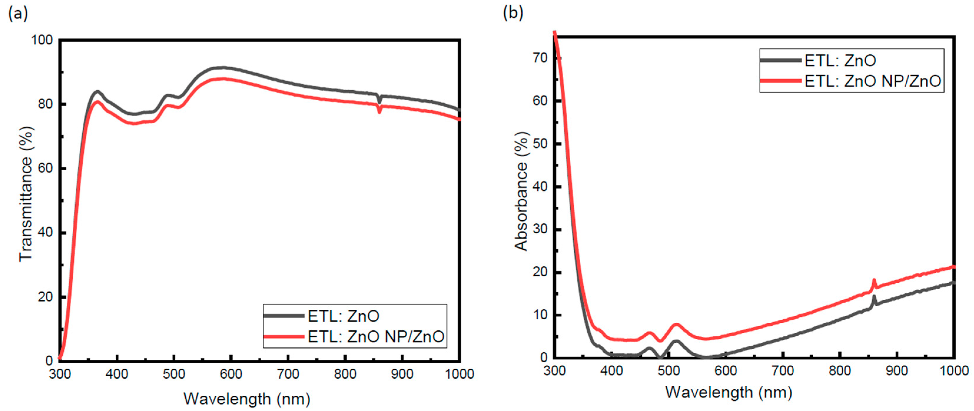
Figure 2 shows the quantitative results of an analysis of the transmission and absorption spectra of the electron transport layers (ETLs). All the films have approximately 82% transparency within the visible spectrum. When comparing single-layer ZnO with a bilayer electron transport layer (ETL), there is no significant difference in transmission quality. Tauc plot analysis, as shown in Figure S1, was used to calculate the bandgap of the ETLs. The presence of the ITO-coated glass substrate may be ascribed to the decrease in absorption at 450 nm in the transmission spectra [56]. The absorbance spectra of the films also demonstrated that the peak absorption occurred within the visual range. The thickness of the bilayer ZnO NP/ZnO is substantially greater than that of the monolayer. However, it is possible that the absorption characteristics of the photovoltaic layer are not significantly affected by these phenomena. As a result, the ETLs allow a significant amount of visible light to reach the active layer.

3.3. Morphological Properties

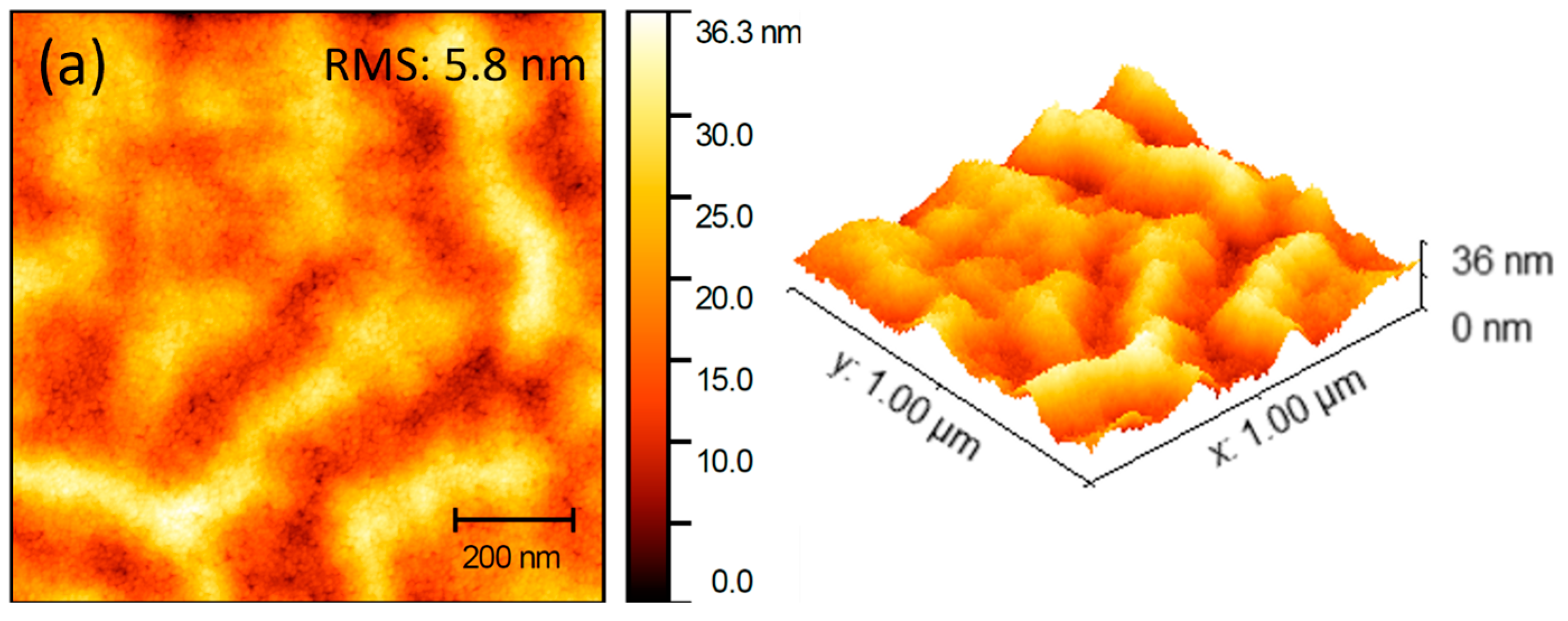
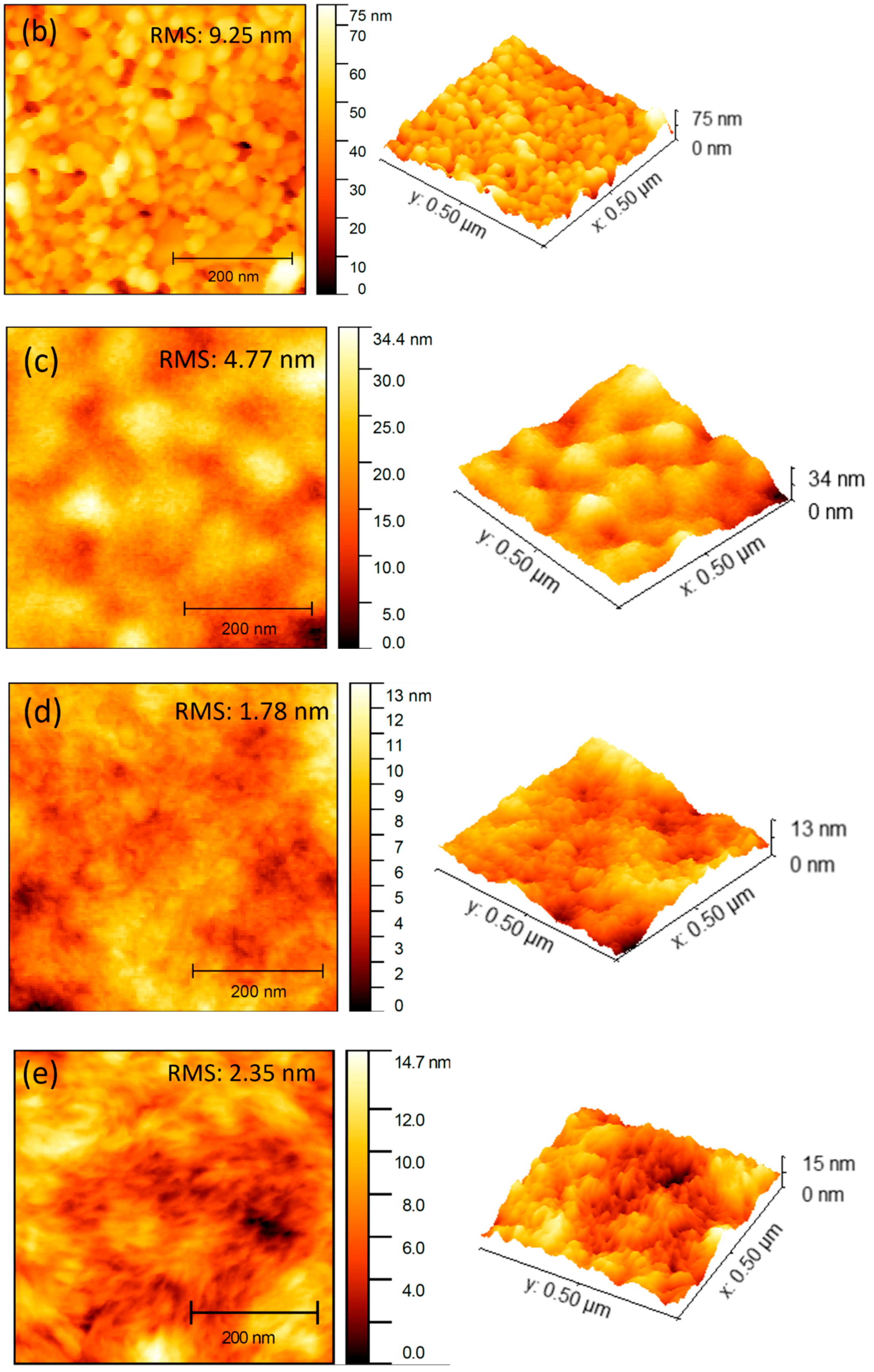
Figure 3 and Figure 4 show the results of atomic force microscopy (AFM) and scanning electron microscopy (SEM) analyses of the surface morphologies of sol-gel ZnO, ZnO NP, and bilayer ZnO films on ITO substrates. Table 1 displays the results of atomic force microscopy (AFM) characterization of the root mean square roughness (Rrms). The sol-gel ZnO layer displays a surface that is particularly smooth, as evidenced by a root mean square roughness (Rrms) value of 5.8 nm (Figure 3a). The Rrms value of 9.25 nm indicates that the surface roughness of a single layer of ZnO nanoparticles significantly increased. Similar findings were reported by Fan et al. [57] in their investigation of a ZnO NP ETL on an ITO glass substrate. The morphology of ZnO nanoparticles (ZnO-NPs) is defined by a rough particle structure that is characterized by the existence of voids. Surface imperfections, as stated above, might enhance the likelihood of exciton entrapment and recombination [58]. Figure 3b shows the ZnO film NPs, and Figure 3c shows the bilayer ZnO film. The highly crystalline ZnO NPs have a smoother surface after the integration of the sol-gel ZnO film. The pinholes of the ZnO nanoparticles were significantly reduced in size and number when an additional layer with amorphous properties was included in the structure. The interfacial characteristics of the bilayer ZnO surface are predicted to improve as a consequence of these phenomena [59].
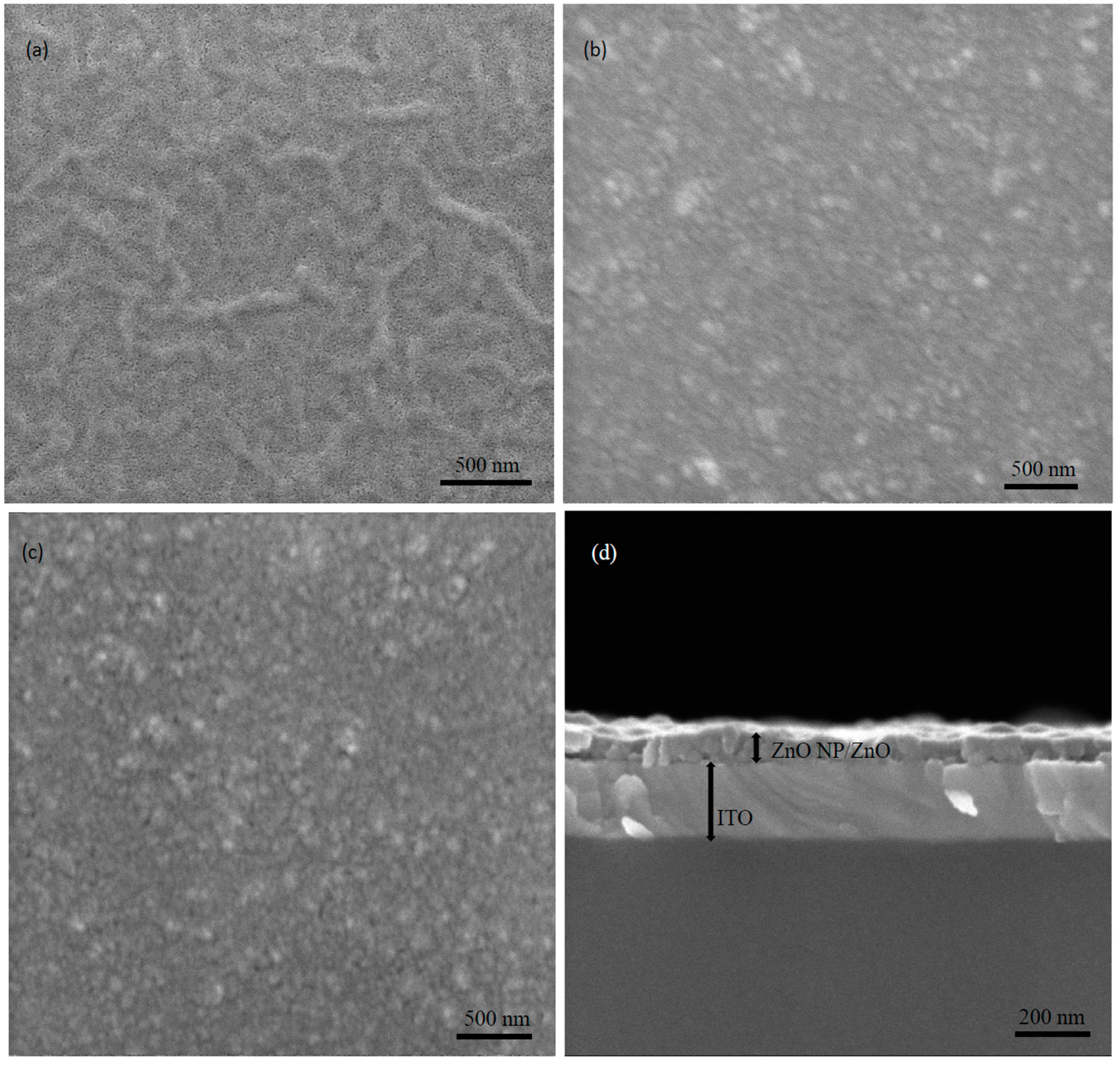
The absence of crystallinity in the sol-gel ZnO film was further confirmed by scanning electron microscopy (SEM) as previously mentioned, as shown in Figure 4a. Incorporating a sol-gel ZnO film results in the production of a more refined surface for widely crystalline ZnO NPs, as shown by a comparison between the ZnO NP film displayed in Figure 4b and the bilayer ZnO film depicted in Figure 4c. The pinholes of the ZnO nanoparticles were significantly reduced in size when an additional layer with amorphous properties was introduced between the aggregated nanoparticles. Figure 4d represents the cross-section view of the bilayer ZnO NP/ZnO ETL, confirming good contact with the ITO substrate. The indicated effect of this study is the enhancement of interfacial characteristics with regard to the bilayer ZnO surface.

3.4. Elemental States

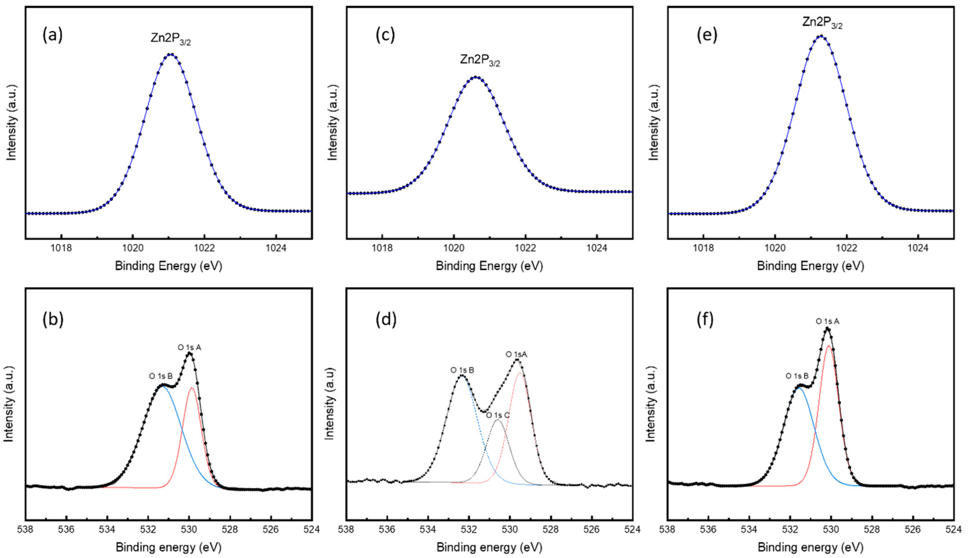
The X-ray photoelectron spectroscopy (XPS) technique was employed to better understand the elemental composition and electrical characteristics [60]. X-ray photoelectron spectroscopy (XPS) was used to analyze the chemical compositions of distinct layers in the ZnO, ZnO-NP, and bilayer films produced on an indium tin oxide (ITO) glass substrate. To analyze the spectral data, the Shirley background method was used inside the Avantage program [61]. The spectra from the XPS survey are shown in Figure S2. High-resolution O1s X-ray photoelectron spectroscopy (XPS) images were taken of the ETL films, and the envelope curve and deconvoluted Gaussian sub-peaks are shown in Figure 5. The peak binding energies, peak full width at half maximum (FWHM), and percentages of atomic elements are shown in Table S3. Figure 5 shows the existence of three Gaussian subpeaks, labeled O1s A, O1s B, and O1s C, in each of the three ETL films. The O1s A, O1s B, and O1s C subpeaks of ZnO films are often related to chemical reactions between nearby zinc and oxygen atoms. ZnO bonds are responsible for the occurrence of lattice oxygen (OL), with oxygen ions found in oxygen-deficient areas having a binding energy somewhere in the middle. The existence of oxygen vacancies (VO) often accompanies these oxygen deficiency states. Conversely, the higher binding energy may be attributed to the presence of nonlattice oxygen (OC), signaling the presence of chemisorbed or dissociated oxygen and hydroxyl groups (-OH) [62,63,64]. Only the O1s A and O1s B peaks may be found in the spectra of the ZnO and bilayer films. An additional O1s C peak is observed for the ZnO-NP film, suggesting a greater number of oxygen-poor areas. Such regions in ZnO-NPs may serve as recombination centers for photogenerated holes and electrons, leading to a lower fill factor (FF) and power conversion efficiency (PCE) [65]. Zinc oxide (ZnO) deposited on top of ZnO nanoparticles reduced oxygen deficit, leading to increased photovoltaic performance in bilayer organic solar cell (OSC) devices.

3.5. Photovoltaic Performances

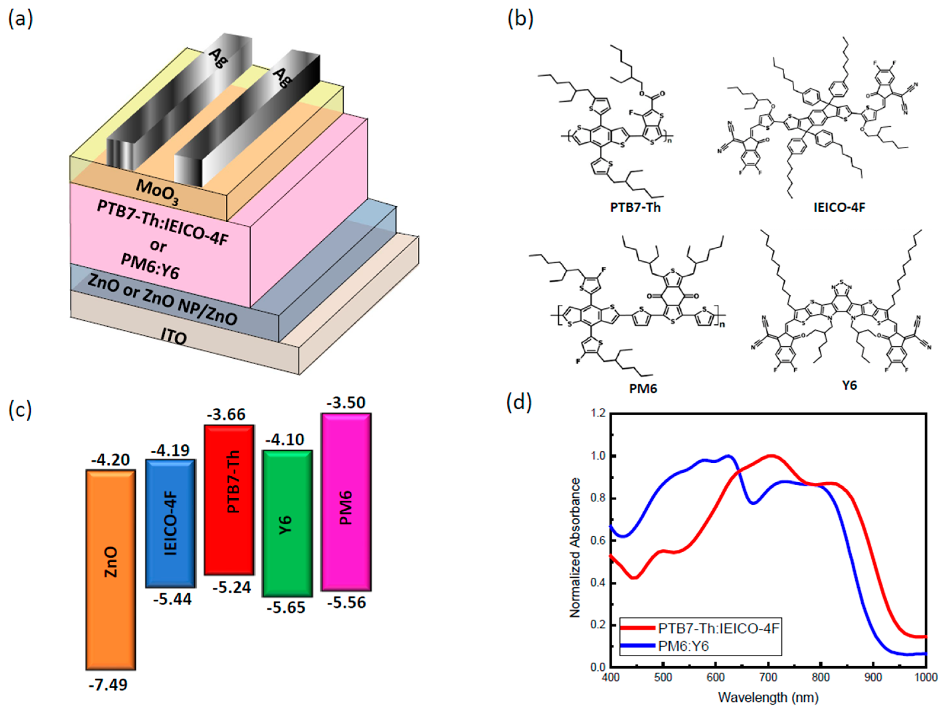
The primary objective of the present study was to examine the production of organic solar cells using two specific conjugated polymer materials, namely PTB7-Th and PM6, as donor materials. Additionally, two non-fullerene materials, IEICO-4F and Y6, were used as acceptor materials in this analysis. The organic solar cells (OSCs) shown in Figure 6a were produced using an inverted architecture that included the following layers: ITO/ZnO/PTB7-Th:IEICO-4F/MoO3/Ag and ITO/ZnO/PM6:Y6/MoO3/Ag. Figure 6b shows the molecular structure of the donor and acceptor materials, while Figure 6c,d display the energy band diagrams and absorption spectra of the donor and acceptor materials, respectively. The aim of this work was to apply a bilayer ZnO NP/ZnO electron transport layer (ETL) to two distinct systems to examine the impact of interface engineering on the active layers of these materials.
The findings of the electrical performance investigation performed on the constructed PTB7-Th:IEICO-4F and PM6:Y6 active layers-based organic solar cell (OSC) devices using different electron transport layers (ETLs) are shown in Figure 7a,d. The photovoltaic performance metrics, including open-circuit voltage (Voc), current density (Jsc), fill factor (FF), and power conversion efficiency (PCE), are shown in Table 2. The PCE of 9.18% for the control device is consistent with the results published in earlier academic publications. A Jsc value of 22.08 mW/cm2, a Voc value of 0.735 V, and an FF value of 56.29% were obtained by the control device. By incorporating ZnO NPs between the ITO and ZnO layers, the device’s PCE improved from 9.18% to 10.2%. It is obvious that the parameters Voc, Jsc, and FF also increased in the ZnO NP/ZnO bilayer devices. The device based on PM6:Y6 exhibited similar characteristics to the device based on PTB7-Th:IEICO-4F, as shown in Figure 7c,f. The highest efficiency attained for devices based on PM6:Y6 was 14.6%. The statistical distribution of others photovoltaic parameters Voc, Jsc, and FF are shown in Figure S3. The bilayer devices exhibit a concurrent improvement in all photovoltaic parameters as compared to the ZnO control device. Table 2 presents the photovoltaic properties of devices based on PTB7-Th:IEICO-4F and PM6:Y6, including the power conversion efficiency (PCE), open-circuit voltage (Voc), short-circuit current density (Jsc), fill factor (FF), shunt resistance (Rsh), and series resistance (Rs).
The external quantum efficiency (EQE) spectra of devices using different ETLs were examined, and the results are compared in Figure 7b,e providing a more in-depth examination of the considerable improvement in Jsc. There is a great degree of consistency between the EQE and ETLs. In contrast to devices that use sol-gel ZnO ETLs, devices that use bilayer ZnO ETLs provide an improvement in the EQE of 350–700 nm.
Both the ITO/ZnO/PTB7-Th:IEICO-4F/MoO3/Ag and ITO/ZnO/PM6:Y6/MoO3/Ag OSC devices displayed a maximum EQE of approximately 85% when optimized with a bilayer ZnO electron transport layer (ETL). These results provide conclusive evidence supporting the reported increase in photocurrent for the bilayer ZnO configuration.
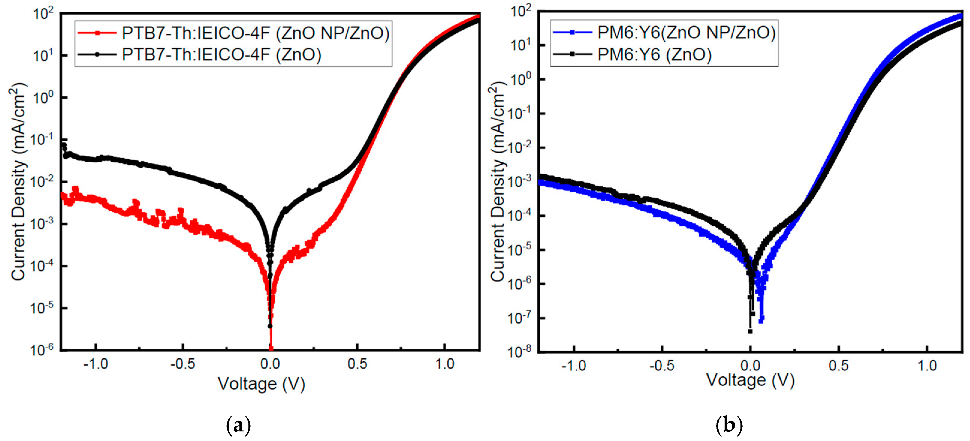
The dark J-V curves for each device employing different combinations of ETLs in the PM6:Y6- and PTB7-Th:IEICO-4F-based devices are shown in Figure 8. The existence of leakage current in the device is shown by the intersection of the J-V curve with the y-axis under reverse bias [62,66]. Among the devices investigated, the PTB7-Th:IEICO-4F and PM6:Y6 devices with bilayer ETLs were found to have the lowest leakage current. A low leakage current results in a high shunt resistance (Rsh) for organic solar cells. This property is indicative of high charge transport efficiency and little charge recombination [67].
The bilayer ZnO NP/ZnO device’s stated decrease in leakage current is responsible for the observed increase in the fill factor (FF) and short-circuit current (Jsc). The interfacial charge transfer properties are responsible for the considerable variation in reverse bias leakage conditions observed in this research. It is essential to acknowledge that the enquiry conducted in this work centered only on the manufacturing process of ZnO [68]. Compared to sol-gel ZnO ETL devices, bilayer ZnO ETL devices have a higher short-circuit current density (Jsc). The decrease in leakage current reported in the bilayer ZnO device may be due to the better interfacial morphology and increased crystallinity. The short-circuit current density (Jsc) and fill factor (FF) are both enhanced as a consequence of the aforementioned changes [69,70].
To assess how a device responds to an alternating current (AC) input, electrochemical impedance spectroscopy (EIS) is often used. The applied voltage chosen for both types of devices was 0.6 V, which was slightly lower than the open-circuit voltage (Voc). When exposed to a low voltage bias, the traps existing in the active layer can react to the modified signal. On the other hand, when exposed to a higher voltage bias, the trap state has the capacity to hinder the response [62,71,72]. The Nyquist plots produced from electrochemical impedance spectroscopy (EIS) studies are shown in Figure 9.
As shown in Figure 9, the plots were evaluated by fitting them with an equivalent electrical circuit. The electrical circuit was composed of a solitary resistance circuit and two parallel connections consisting of resistance and capacitance (RC). The analogous circuit model elucidates the relationship between the series resistance (Rs) and the sheet resistance of the electrodes and electrical contacts. Both the resistance at the interface between the electrode and the bulk heterojunction (BHJ) layer and the resistance inside the active layer are related to the resistance of charge transport (Rt) [73,74]. The carrier recombination resistance (Rrec) is a parameter that provides insight into the nonradiative recombination processes occurring within a device. The dielectric capacitance of the device is denoted as Cg, whereas the dispersed chemical capacitance is represented as Cμ [75,76] Table S4 presents a concise overview of the estimated parameters of the analogous circuit. The observed reduction in transport resistance indicates that the incorporation of a ZnO NP/ZnO bilayer electron transport layer (ETL) in organic solar cells (OSCs) leads to a decrease in contact resistance, possibly enhancing the efficiency of charge extraction. As previously mentioned, the findings of this study provide additional support for the theory that the integration of ZnO nanoparticles (NPs) between a ZnO layer and an ITO-coated glass substrate results in advantageous outcomes for the effective operation of inverted photovoltaic systems.

3.6. Stability Measurement

Stability of OSCs represents a crucial factor for commercialization. Therefore, it is necessary to clarify the factors affecting photovoltaic performance and device lifetime [77,78]. Hereupon, the efficiency is attenuated with ZnO and ZnO NP/ZnO ELTs for both (PTB7-Th:IEICO-4F and PM6:Y6) types of devices. All the devices were stored for aging over 10 days and then tested, as shown in Figure 10. Figure 10a,b show the normalized PCEs of both types of devices and Figure 10c,d show SEM images of bilayers for both fresh and aged devices and Figure S4 shows cross-sectional SEM images for fresh bilayer ZnO NP/ZnO and aged samples on ITO substrate. From SEM, it can be seen that there are some tiny pinholes on the aged sample surface, which may cause slightly lower performance of the aged bilayer device compared to the fresh bilayer device. The efficiency of the sol-gel ZnO NP/ZnO bilayer ETL OSCs remained above 90% even after a period of 10 days, demonstrating their better stability compared to the control devices. The control devices’ performance degradation primarily resulted from a decrease in FF, suggesting that the long-term stability was impacted by interface degradation. The rapid deterioration of the ZnO device performance is mainly attributed to the presence of excess -OH groups, which enhance the photocatalytic effect of ZnO and consequently expedite the device degradation [45,79,80]. The inclusion of ZnO nanoparticles between the ZnO and active layer has been found to significantly decrease surface defects and recombination at the interface. This reduction is the primary factor contributing to the enhanced stability observed in ZnO NP/ZnO electron transport layer (ETL) devices.

4. Conclusions

In summary, this study successfully conducted interfacial modification on a ZnO film by including an extra layer of ZnO nanoparticles that functioned as an electron transport layer. By strengthening the film’s electron transport capabilities, this hybrid bilayer seeks to maximize its performance. Inverted devices with photoactive layers of PTB7-Th:IEICO-4F and PM6:Y6 benefit from a bilayer approach, which increases their photovoltaic efficiency. There was a noticeable improvement in efficiency from 9.18% to 10.2% in the PTB7-Th:IEICO-4F-based device. In comparison, the device using PM6:Y6 showed an improvement in efficiency, with a rise from 13.95% to 14.6%. The primary reason for the observed increase in the efficiency of the ZnO NP/ZnO devices could be attributed to the simultaneous increases in Jsc and FF. The primary driving factors behind this improvement are the enhanced capacity for charge transport and the effective mitigation of charge recombination processes. The developed ZnO NP/ZnO interlayer exhibited enhanced electron extraction efficiency. As a result of its greatly reduced work function, it is able to align with the lowest unoccupied molecular orbital (LUMO) of the acceptor. In addition, the inclusion of this interlayer enables the formation of a continuous and unobstructed interface with the photoactive layer. It was also shown that the ZnO NP/ZnO interlayer exhibited higher interlayer conductivity than the pure ZnO interlayer. The strong effect of the remarkable properties of the ZnO NP/ZnO bilayer on the processes of charge extraction, transport, and recombination in organic solar cell (OSC) devices is highly relevant. This work focused on the use of a bilayer consisting of ZnO nanoparticles (NPs) and ZnO for modifying the interface of ZnO. The main aim is to improve the efficiency of organic solar cells (OSCs) by boosting their photovoltaic performance.

Supplementary Materials

The following supporting information can be downloaded at: https://www.mdpi.com/article/10.3390/nanomanufacturing4020006/s1, Figure S1: Bandgap of ZnO ETL and ZnO NP/ZnO ETL determined from the Tauc plot; Figure S2: X-Ray photoelectron spectroscopy (XPS) survey spectra of (a) ZnO, (b) ZnO-NP and (c) bilayer ETLs, on ITO/glass substrate, demonstrating the elemental peaks; Figure S3: Statistical distribution of the device parameters (devices with ZnO and bilayer ZnO NP/ZnO) displayed (a,d) Voc (V), (b,e) Jsc (mA/cm2), and (c,f) FF (%). 10 cells have been tested for each case. A bilayer device exhibits a simultaneous improvement in all photovoltaic parameters compared to the ZnO control device; Figure S4: (a,b) Cross-section SEM images of fresh and aged bilayer ZnO NP/ZnO ETL; Table S1: Photovoltaic parameters of organic solar cells with ZnO-based electron transport layer (ETL); Table S2: XRD parameters for ZnO, ZnO NP, and ZnO NP/ZnO ELTs; Table S3: Peak binding energy, peak full width at half maximum, and atomic percentage of ETL films (ZnO, ZnO-NP and bilayer) from X-Ray photoelectron spectroscopy (XPS) data. Table S4: Electrical parameters extracted from Nyquist plot for ZnO only and ZnO NP/ZnO devices.

Author Contributions

Conceptualization, W.B.T. and M.H.R.; methodology, W.B.T.; validation, W.B.T., S.S.D., M.H.R. and A.H.H.; formal analysis, W.B.T.; investigation, W.B.T.; resources, A.U.; data curation, W.B.T., S.S.D. and A.H.H.; writing—original draft preparation, W.B.T.; writing—review and editing, W.B.T., M.H.R., S.S.D., A.H.H. and A.U.; visualization, W.B.T. and A.U.; supervision, A.U.; project administration, A.U.; funding acquisition, A.U. All authors have read and agreed to the published version of the manuscript.

Funding

The authors would like to acknowledge the Australian Research Council (ARC), Discovery Project (DP210100904) grants for financial support for this study.

Data Availability Statement

Data is contained within the article or Supplementary Materials.

Acknowledgments

The authors express their gratitude for the constant support provided by the personnel of the Photovoltaic and Renewable Energy Engineering School, the Electron Microscope Unit, and the Solid State and Elemental Analysis Unit in the Mark Wainwright Analytical Centre at the University of New South Wales.

Conflicts of Interest

The authors declare no conflict of interest.

References

  1. Yip, H.-L.; Jen, A.K.-Y. Recent Advances in Solution-Processed Interfacial Materials for Efficient and Stable Polymer Solar Cells. Energy Environ. Sci. 2012, 5, 5994–6011. [Google Scholar] [CrossRef]
  2. Ongul, F. Solution-Processed Inverted Organic Solar Cell Using V2O5 Hole Transport Layer and Vacuum Free EGaIn Anode. Opt. Mater. 2015, 50, 244–249. [Google Scholar] [CrossRef]
  3. Fu, H.; Li, Y.; Yu, J.; Wu, Z.; Fan, Q.; Lin, F.; Woo, H.Y.; Gao, F.; Zhu, Z.; Jen, A.K.-Y. High Efficiency (15.8%) All-Polymer Solar Cells Enabled by a Regioregular Narrow Bandgap Polymer Acceptor. J. Am. Chem. Soc. 2021, 143, 2665–2670. [Google Scholar] [CrossRef]
  4. Sun, C.; Pan, F.; Bin, H.; Zhang, J.; Xue, L.; Qiu, B.; Wei, Z.; Zhang, Z.-G.; Li, Y. A Low Cost and High Performance Polymer Donor Material for Polymer Solar Cells. Nat. Commun. 2018, 9, 743. [Google Scholar] [CrossRef]
  5. Chen, J.-D.; Cui, C.; Li, Y.-Q.; Zhou, L.; Ou, Q.-D.; Li, C.; Li, Y.; Tang, J.-X. Single-Junction Polymer Solar Cells Exceeding 10% Power Conversion Efficiency. Adv. Mater. 2015, 27, 1035–1041. [Google Scholar] [CrossRef]
  6. He, Z.; Xiao, B.; Liu, F.; Wu, H.; Yang, Y.; Xiao, S.; Wang, C.; Russell, T.P.; Cao, Y. Single-Junction Polymer Solar Cells with High Efficiency and Photovoltage. Nat. Photon 2015, 9, 174–179. [Google Scholar] [CrossRef]
  7. Chen, H.; Hu, D.; Yang, Q.; Gao, J.; Fu, J.; Yang, K.; He, H.; Chen, S.; Kan, Z.; Duan, T.; et al. All-Small-Molecule Organic Solar Cells with an Ordered Liquid Crystalline Donor. Joule 2019, 3, 3034–3047. [Google Scholar] [CrossRef]
  8. Zhou, R.; Jiang, Z.; Yang, C.; Yu, J.; Feng, J.; Adil, M.A.; Deng, D.; Zou, W.; Zhang, J.; Lu, K.; et al. All-Small-Molecule Organic Solar Cells with over 14% Efficiency by Optimizing Hierarchical Morphologies. Nat. Commun. 2019, 10, 5393. [Google Scholar] [CrossRef]
  9. Gao, H.; Sun, Y.; Meng, L.; Han, C.; Wan, X.; Chen, Y. Recent Progress in All-Small-Molecule Organic Solar Cells. Small 2023, 19, 2205594. [Google Scholar] [CrossRef] [PubMed]
  10. Eisner, F.; Seitkhan, A.; Han, Y.; Khim, D.; Yengel, E.; Kirmani, A.R.; Xu, J.; de Arquer, F.P.G.; Sargent, E.H.; Amassian, A.; et al. Solution-Processed In2O3/ZnO Heterojunction Electron Transport Layers for Efficient Organic Bulk Heterojunction and Inorganic Colloidal Quantum-Dot Solar Cells. Sol. RRL 2018, 2, 1800076. [Google Scholar] [CrossRef]
  11. Bashir, R.; Kashif Bilal, M.; Bashir, A.; Zhao, J.; Asif, S.U.; Ahmad, W.; Xie, J.; Hu, W. A Low-Temperature Solution-Processed Indium Incorporated Zinc Oxide Electron Transport Layer for High-Efficiency Lead Sulfide Colloidal Quantum Dot Solar Cells. Nanoscale 2021, 13, 12991–12999. [Google Scholar] [CrossRef]
  12. Ren, X.; Yang, D.; Yang, Z.; Feng, J.; Zhu, X.; Niu, J.; Liu, Y.; Zhao, W.; Liu, S.F. Solution-Processed Nb:SnO2 Electron Transport Layer for Efficient Planar Perovskite Solar Cells. ACS Appl. Mater. Interfaces 2017, 9, 2421–2429. [Google Scholar] [CrossRef]
  13. Ke, W.; Fang, G.; Liu, Q.; Xiong, L.; Qin, P.; Tao, H.; Wang, J.; Lei, H.; Li, B.; Wan, J.; et al. Low-Temperature Solution-Processed Tin Oxide as an Alternative Electron Transporting Layer for Efficient Perovskite Solar Cells. J. Am. Chem. Soc. 2015, 137, 6730–6733. [Google Scholar] [CrossRef]
  14. Ma, J.; Lin, Z.; Guo, X.; Zhou, L.; Su, J.; Zhang, C.; Yang, Z.; Chang, J.; Liu, S.; Hao, Y. Low-Temperature Solution-Processed ZnO Electron Transport Layer for Highly Efficient and Stable Planar Perovskite Solar Cells with Efficiency Over 20%. Sol. RRL 2019, 3, 1900096. [Google Scholar] [CrossRef]
  15. Mahmud, M.A.; Elumalai, N.K.; Upama, M.B.; Wang, D.; Chan, K.H.; Wright, M.; Xu, C.; Haque, F.; Uddin, A. Low Temperature Processed ZnO Thin Film as Electron Transport Layer for Efficient Perovskite Solar Cells. Sol. Energy Mater. Sol. Cells 2017, 159, 251–264. [Google Scholar] [CrossRef]
  16. Jørgensen, M.; Norrman, K.; Krebs, F.C. Stability/Degradation of Polymer Solar Cells. Sol. Energy Mater. Sol. Cells 2008, 92, 686–714. [Google Scholar] [CrossRef]
  17. Salsberg, E.; Aziz, H. Degradation of PEDOT:PSS Hole Injection Layers by Electrons in Organic Light Emitting Devices. Org. Electron. 2019, 69, 313–319. [Google Scholar] [CrossRef]
  18. Vohra, V.; Kawashima, K.; Kakara, T.; Koganezawa, T.; Osaka, I.; Takimiya, K.; Murata, H. Efficient Inverted Polymer Solar Cells Employing Favourable Molecular Orientation. Nat. Photon 2015, 9, 403–408. [Google Scholar] [CrossRef]
  19. Small, C.E.; Chen, S.; Subbiah, J.; Amb, C.M.; Tsang, S.-W.; Lai, T.-H.; Reynolds, J.R.; So, F. High-Efficiency Inverted Dithienogermole–Thienopyrrolodione-Based Polymer Solar Cells. Nat. Photon 2012, 6, 115–120. [Google Scholar] [CrossRef]
  20. Sun, Y.; Seo, J.H.; Takacs, C.J.; Seifter, J.; Heeger, A.J. Inverted Polymer Solar Cells Integrated with a Low-Temperature-Annealed Sol-Gel-Derived ZnO Film as an Electron Transport Layer. Adv. Mater. 2011, 23, 1679–1683. [Google Scholar] [CrossRef]
  21. Kyaw, A.K.K.; Sun, X.W.; Jiang, C.Y.; Lo, G.Q.; Zhao, D.W.; Kwong, D.L. An Inverted Organic Solar Cell Employing a Sol-Gel Derived ZnO Electron Selective Layer and Thermal Evaporated MoO3 Hole Selective Layer. Appl. Phys. Lett. 2008, 93, 221107. [Google Scholar] [CrossRef]
  22. Cowan, S.R.; Schulz, P.; Giordano, A.J.; Garcia, A.; MacLeod, B.A.; Marder, S.R.; Kahn, A.; Ginley, D.S.; Ratcliff, E.L.; Olson, D.C. Chemically Controlled Reversible and Irreversible Extraction Barriers Via Stable Interface Modification of Zinc Oxide Electron Collection Layer in Polycarbazole-Based Organic Solar Cells. Adv. Funct. Mater. 2014, 24, 4671–4680. [Google Scholar] [CrossRef]
  23. Huang, J.-H.; Wei, H.-Y.; Huang, K.-C.; Chen, C.-L.; Wang, R.-R.; Chen, F.-C.; Ho, K.-C.; Chu, C.-W. Using a Low Temperature Crystallization Process to Prepare Anatase TiO2 Buffer Layers for Air-Stable Inverted Polymer Solar Cells. Energy Environ. Sci. 2010, 3, 654–658. [Google Scholar] [CrossRef]
  24. Tran, V.-H.; Eom, S.H.; Yoon, S.C.; Kim, S.-K.; Lee, S.-H. Enhancing Device Performance of Inverted Organic Solar Cells with SnO2/Cs2CO3 as Dual Electron Transport Layers. Org. Electron. 2019, 68, 85–95. [Google Scholar] [CrossRef]
  25. Yang, H.B.; Dong, Y.Q.; Wang, X.; Khoo, S.Y.; Liu, B. Cesium Carbonate Functionalized Graphene Quantum Dots as Stable Electron-Selective Layer for Improvement of Inverted Polymer Solar Cells. ACS Appl. Mater. Interfaces 2014, 6, 1092–1099. [Google Scholar] [CrossRef] [PubMed]
  26. Wei, J.; Zhang, C.; Ji, G.; Han, Y.; Ismail, I.; Li, H.; Luo, Q.; Yang, J.; Ma, C.-Q. Roll-to-Roll Printed Stable and Thickness-Independent ZnO:PEI Composite Electron Transport Layer for Inverted Organic Solar Cells. Sol. Energy 2019, 193, 102–110. [Google Scholar] [CrossRef]
  27. Liu, C.; Xiao, C.; Xie, C.; Li, W. Flexible Organic Solar Cells: Materials, Large-Area Fabrication Techniques and Potential Applications. Nano Energy 2021, 89, 106399. [Google Scholar] [CrossRef]
  28. Wang, J.-C.; Weng, W.-T.; Tsai, M.-Y.; Lee, M.-K.; Horng, S.-F.; Perng, T.-P.; Kei, C.-C.; Yu, C.-C.; Meng, H.-F. Highly Efficient Flexible Inverted Organic Solar Cells Using Atomic Layer Deposited ZnO as Electron Selective Layer. J. Mater. Chem. 2010, 20, 862–866. [Google Scholar] [CrossRef]
  29. Ko, S.H.; Lee, D.; Kang, H.W.; Nam, K.H.; Yeo, J.Y.; Hong, S.J.; Grigoropoulos, C.P.; Sung, H.J. Nanoforest of Hydrothermally Grown Hierarchical ZnO Nanowires for a High Efficiency Dye-Sensitized Solar Cell. Nano Lett. 2011, 11, 666–671. [Google Scholar] [CrossRef]
  30. Sanchez, S.; Berson, S.; Guillerez, S.; Lévy-Clément, C.; Ivanova, V. Toward High-Stability Inverted Polymer Solar Cells with an Electrodeposited ZnO Electron Transporting Layer. Adv. Energy Mater. 2012, 2, 541–545. [Google Scholar] [CrossRef]
  31. Lin, R.; Miwa, M.; Wright, M.; Uddin, A. Optimisation of the Sol–Gel Derived ZnO Buffer Layer for Inverted Structure Bulk Heterojunction Organic Solar Cells Using a Low Band Gap Polymer. Thin Solid Film. 2014, 566, 99–107. [Google Scholar] [CrossRef]
  32. Soultati, A.; Fakharuddin, A.; Polydorou, E.; Drivas, C.; Kaltzoglou, A.; Haider, M.I.; Kournoutas, F.; Fakis, M.; Palilis, L.C.; Kennou, S.; et al. Lithium Doping of ZnO for High Efficiency and Stability Fullerene and Non-Fullerene Organic Solar Cells. ACS Appl. Energy Mater. 2019, 2, 1663–1675. [Google Scholar] [CrossRef]
  33. Xu, X.; Xiao, J.; Zhang, G.; Wei, L.; Jiao, X.; Yip, H.-L.; Cao, Y. Interface-Enhanced Organic Solar Cells with Extrapolated T80 Lifetimes of over 20 years. Sci. Bull. 2020, 65, 208–216. [Google Scholar] [CrossRef]
  34. Rahaman, H.; Sang, B.; Hossain, A.; Hoex, B.; Mota-Santiago, P.; Mitchell, V.D.; Uddin, A.; Stride, J.A. Impact of the Bilayer Electron Transport Layer in the Donor Acceptor Bulk Heterojunctions for Improved Inverted Organic Photovoltaic Performance. Appl. Surf. Sci. 2023, 612, 155669. [Google Scholar] [CrossRef]
  35. Gong, X. Toward High Performance Inverted Polymer Solar Cells. Polymer 2012, 53, 5437–5448. [Google Scholar] [CrossRef]
  36. Jin, W.-Y.; Ginting, R.T.; Jin, S.-H.; Kang, J.-W. Highly Stable and Efficient Inverted Organic Solar Cells Based on Low-Temperature Solution-Processed PEIE and ZnO Bilayers. J. Mater. Chem. A 2016, 4, 3784–3791. [Google Scholar] [CrossRef]
  37. Cheng, H.-W.; Raghunath, P.; Wang, K.; Cheng, P.; Haung, T.; Wu, Q.; Yuan, J.; Lin, Y.-C.; Wang, H.-C.; Zou, Y.; et al. Potassium-Presenting Zinc Oxide Surfaces Induce Vertical Phase Separation in Fullerene-Free Organic Photovoltaics. Nano Lett. 2020, 20, 715–721. [Google Scholar] [CrossRef] [PubMed]
  38. Zheng, Z.; Zhang, S.; Wang, J.; Zhang, J.; Zhang, D.; Zhang, Y.; Wei, Z.; Tang, Z.; Hou, J.; Zhou, H. Exquisite Modulation of ZnO Nanoparticle Electron Transporting Layer for High-Performance Fullerene-Free Organic Solar Cell with Inverted Structure. J. Mater. Chem. A 2019, 7, 3570–3576. [Google Scholar] [CrossRef]
  39. Lee, S.-H.; Ko, S.-J.; Eom, S.H.; Kim, H.; Kim, D.W.; Lee, C.; Yoon, S.C. Composite Interlayer Consisting of Alcohol-Soluble Polyfluorene and Carbon Nanotubes for Efficient Polymer Solar Cells. ACS Appl. Mater. Interfaces 2020, 12, 14244–14253. [Google Scholar] [CrossRef]
  40. Upama, M.B.; Elumalai, N.K.; Mahmud, M.A.; Wright, M.; Wang, D.; Xu, C.; Haque, F.; Chan, K.H.; Uddin, A. Interfacial Engineering of Electron Transport Layer Using Caesium Iodide for Efficient and Stable Organic Solar Cells. Appl. Surf. Sci. 2017, 416, 834–844. [Google Scholar] [CrossRef]
  41. Huang, S.; Kang, B.; Duan, L.; Zhang, D. Highly Efficient Inverted Polymer Solar Cells by Using Solution Processed MgO/ZnO Composite Interfacial Layers. J. Colloid Interface Sci. 2021, 583, 178–187. [Google Scholar] [CrossRef]
  42. Zhu, X.; Guo, B.; Fang, J.; Zhai, T.; Wang, Y.; Li, G.; Zhang, J.; Wei, Z.; Duhm, S.; Guo, X.; et al. Surface Modification of ZnO Electron Transport Layers with Glycine for Efficient Inverted Non-Fullerene Polymer Solar Cells. Org. Electron. 2019, 70, 25–31. [Google Scholar] [CrossRef]
  43. Pan, W.; Han, Y.; Wang, Z.; Gong, C.; Guo, J.; Lin, J.; Luo, Q.; Yang, S.; Ma, C.-Q. An Efficiency of 14.29% and 13.08% for 1 cm2 and 4 cm2 Flexible Organic Solar Cells Enabled by Sol–Gel ZnO and ZnO Nanoparticle Bilayer Electron Transporting Layers. J. Mater. Chem. A 2021, 9, 16889–16897. [Google Scholar] [CrossRef]
  44. Mahmud, M.A.; Elumalai, N.K.; Upama, M.B.; Wang, D.; Soufiani, A.M.; Wright, M.; Xu, C.; Haque, F.; Uddin, A. Solution-Processed Lithium-Doped ZnO Electron Transport Layer for Efficient Triple Cation (Rb, MA, FA) Perovskite Solar Cells. ACS Appl. Mater. Interfaces 2017, 9, 33841–33854. [Google Scholar] [CrossRef]
  45. Duan, L.; Guli, M.; Zhang, Y.; Yi, H.; Haque, F.; Uddin, A. The Air Effect in the Burn-In Thermal Degradation of Nonfullerene Organic Solar Cells. Energy Technol. 2020, 8, 1901401. [Google Scholar] [CrossRef]
  46. Xu, C.; Wright, M.; Elumalai, N.K.; Mahmud, M.A.; Wang, D.; Upama, M.B.; Haque, F.; Uddin, A. Highly Crystalline Bilayer Electron Transport Layer for Efficient Conjugated Polymer Solar Cells. Curr. Appl. Phys. 2018, 18, 505–511. [Google Scholar] [CrossRef]
  47. Upama, M.B.; Elumalai, N.K.; Mahmud, M.A.; Xu, C.; Wang, D.; Wright, M.; Uddin, A. Enhanced Electron Transport Enables over 12% Efficiency by Interface Engineering of Non-Fullerene Organic Solar Cells. Sol. Energy Mater. Sol. Cells 2018, 187, 273–282. [Google Scholar] [CrossRef]
  48. Rahaman, M.H.; Holland, J.; Hossain, M.A.; Duan, L.; Hoex, B.; Mota-Santiago, P.; Mitchell, V.D.; Uddin, A.; Stride, J.A. Increased Efficiency of Organic Solar Cells by Seeded Control of the Molecular Morphology in the Active Layer. Sol. RRL 2022, 6, 2200184. [Google Scholar] [CrossRef]
  49. Yuan, J.; Zhang, Y.; Zhou, L.; Zhang, G.; Yip, H.-L.; Lau, T.-K.; Lu, X.; Zhu, C.; Peng, H.; Johnson, P.A.; et al. Single-Junction Organic Solar Cell with over 15% Efficiency Using Fused-Ring Acceptor with Electron-Deficient Core. Joule 2019, 3, 1140–1151. [Google Scholar] [CrossRef]
  50. Fakhar-e-Alam, M.; Rahim, S.; Atif, M.; Aziz, M.H.; Malick, M.I.; Zaidi, S.S.Z.; Suleman, R.; Majid, A. ZnO Nanoparticles as Drug Delivery Agent for Photodynamic Therapy. Laser Phys. Lett. 2013, 11, 025601. [Google Scholar] [CrossRef]
  51. Elumalai, N.K.; Vijila, C.; Jose, R.; Ming, K.Z.; Saha, A.; Ramakrishna, S. Simultaneous Improvements in Power Conversion Efficiency and Operational Stability of Polymer Solar Cells by Interfacial Engineering. Phys. Chem. Chem. Phys. 2013, 15, 19057–19064. [Google Scholar] [CrossRef]
  52. Jao, M.-H.; Liao, H.-C.; Su, W.-F. Achieving a High Fill Factor for Organic Solar Cells. J. Mater. Chem. A 2016, 4, 5784–5801. [Google Scholar] [CrossRef]
  53. Kumar, E.N.; Jose, R.; Archana, P.S.; Vijila, C.; Yusoff, M.M.; Ramakrishna, S. High Performance Dye-Sensitized Solar Cells with Record Open Circuit Voltage Using Tin Oxide Nanoflowers Developed by Electrospinning. Energy Environ. Sci. 2012, 5, 5401–5407. [Google Scholar] [CrossRef]
  54. Liang, Z.; Zhang, Q.; Jiang, L.; Cao, G. ZnO Cathode Buffer Layers for Inverted Polymer Solar Cells. Energy Environ. Sci. 2015, 8, 3442–3476. [Google Scholar] [CrossRef]
  55. Kim, H.P.; Yusoff, A.R.B.M.; Lee, H.J.; Lee, S.J.; Kim, H.M.; Seo, G.J.; Youn, J.H.; Jang, J. Effect of ZnO:Cs2CO3 on the Performance of Organic Photovoltaics. Nanoscale Res. Lett. 2014, 9, 323. [Google Scholar] [CrossRef]
  56. Na, S.-I.; Kim, S.-S.; Jo, J.; Kim, D.-Y. Efficient and Flexible ITO-Free Organic Solar Cells Using Highly Conductive Polymer Anodes. Adv. Mater. 2008, 20, 4061–4067. [Google Scholar] [CrossRef]
  57. Fan, P.; Zhang, D.; Wu, Y.; Yu, J.; Russell, T.P. Polymer-Modified ZnO Nanoparticles as Electron Transport Layer for Polymer-Based Solar Cells. Adv. Funct. Mater. 2020, 30, 2002932. [Google Scholar] [CrossRef]
  58. Han, C.; Cheng, Y.; Chen, L.; Qian, L.; Yang, Z.; Xue, W.; Zhang, T.; Yang, Y.; Cao, W. Enhanced Performance of Inverted Polymer Solar Cells by Combining ZnO Nanoparticles and Poly[(9,9-Bis(3′-(N,N-Dimethylamino)Propyl)-2,7-Fluorene)-Alt-2,7-(9,9-Dioctyfluorene)] as Electron Transport Layer. ACS Appl. Mater. Interfaces 2016, 8, 3301–3307. [Google Scholar] [CrossRef] [PubMed]
  59. Xu, X.; Zhang, H.; Shi, J.; Dong, J.; Luo, Y.; Li, D.; Meng, Q. Highly Efficient Planar Perovskite Solar Cells with a TiO2/ZnO Electron Transport Bilayer. J. Mater. Chem. A 2015, 3, 19288–19293. [Google Scholar] [CrossRef]
  60. Yamashita, T.; Hayes, P. Analysis of XPS Spectra of Fe2+ and Fe3+ Ions in Oxide Materials. Appl. Surf. Sci. 2008, 254, 2441–2449. [Google Scholar] [CrossRef]
  61. Herrera-Gomez, A.; Cabrera-German, D.; Dutoi, A.D.; Vazquez-Lepe, M.; Aguirre-Tostado, S.; Pianetta, P.; Nordlund, D.; Cortazar-Martinez, O.; Torres-Ochoa, A.; Ceballos-Sanchez, O.; et al. Intensity Modulation of the Shirley Background of the Cr 3p Spectra with Photon Energies around the Cr 2p Edge. Surf. Interface Anal. 2018, 50, 246–252. [Google Scholar] [CrossRef]
  62. Yi, H.; Wang, D.; Mahmud, M.A.; Haque, F.; Upama, M.B.; Xu, C.; Duan, L.; Uddin, A. Bilayer SnO2 as Electron Transport Layer for Highly Efficient Perovskite Solar Cells. ACS Appl. Energy Mater. 2018, 1, 6027–6039. [Google Scholar] [CrossRef]
  63. Awan, S.U.; Hasanain, S.K.; Bertino, M.F.; Jaffari, G.H. Ferromagnetism in Li Doped ZnO Nanoparticles: The Role of Interstitial Li. J. Appl. Phys. 2012, 112, 103924. [Google Scholar] [CrossRef]
  64. Hsieh, P.-T.; Chen, Y.-C.; Kao, K.-S.; Wang, C.-M. Luminescence Mechanism of ZnO Thin Film Investigated by XPS Measurement. Appl. Phys. A 2008, 90, 317–321. [Google Scholar] [CrossRef]
  65. Wu, C.-K.; Sivashanmugan, K.; Guo, T.-F.; Wen, T.-C. Enhancement of Inverted Polymer Solar Cells Performances Using Cetyltrimethylammonium-Bromide Modified ZnO. Materials 2018, 11, 378. [Google Scholar] [CrossRef] [PubMed]
  66. Dongaonkar, S.; Servaites, J.D.; Ford, G.M.; Loser, S.; Moore, J.; Gelfand, R.M.; Mohseni, H.; Hillhouse, H.W.; Agrawal, R.; Ratner, M.A.; et al. Universality of Non-Ohmic Shunt Leakage in Thin-Film Solar Cells. J. Appl. Phys. 2010, 108, 124509. [Google Scholar] [CrossRef]
  67. Huang, D.; Li, Y.; Xu, Z.; Zhao, S.; Zhao, L.; Zhao, J. Enhanced Performance and Morphological Evolution of PTB7:PC71BM Polymer Solar Cells by Using Solvent Mixtures with Different Additives. Phys. Chem. Chem. Phys. 2015, 17, 8053–8060. [Google Scholar] [CrossRef] [PubMed]
  68. Duan, L.; Zhang, Y.; Yi, H.; Haque, F.; Deng, R.; Guan, H.; Zou, Y.; Uddin, A. Trade-Off between Exciton Dissociation and Carrier Recombination and Dielectric Properties in Y6-Sensitized Nonfullerene Ternary Organic Solar Cells. Energy Technol. 2020, 8, 1900924. [Google Scholar] [CrossRef]
  69. Huang, J.-S.; Chou, C.-Y.; Lin, C.-F. Efficient and Air-Stable Polymer Photovoltaic Devices with \hboxWO_3–\hboxV_2\hboxO_5 Mixed Oxides as Anodic Modification. IEEE Electron. Device Lett. 2010, 31, 332–334. [Google Scholar] [CrossRef]
  70. Proctor, C.M.; Nguyen, T.-Q. Effect of Leakage Current and Shunt Resistance on the Light Intensity Dependence of Organic Solar Cells. Appl. Phys. Lett. 2015, 106, 083301. [Google Scholar] [CrossRef]
  71. Garcia-Belmonte, G.; Guerrero, A.; Bisquert, J. Elucidating Operating Modes of Bulk-Heterojunction Solar Cells from Impedance Spectroscopy Analysis. J. Phys. Chem. Lett. 2013, 4, 877–886. [Google Scholar] [CrossRef] [PubMed]
  72. Huang, J.; Xu, Z.; Yang, Y. Low-Work-Function Surface Formed by Solution-Processed and Thermally Deposited Nanoscale Layers of Cesium Carbonate. Adv. Funct. Mater. 2007, 17, 1966–1973. [Google Scholar] [CrossRef]
  73. You, J.; Chen, C.-C.; Dou, L.; Murase, S.; Duan, H.-S.; Hawks, S.A.; Xu, T.; Son, H.J.; Yu, L.; Li, G.; et al. Metal Oxide Nanoparticles as an Electron-Transport Layer in High-Performance and Stable Inverted Polymer Solar Cells. Adv. Mater. 2012, 24, 5267–5272. [Google Scholar] [CrossRef] [PubMed]
  74. Wan, Q.; Guo, X.; Wang, Z.; Li, W.; Guo, B.; Ma, W.; Zhang, M.; Li, Y. 10.8% Efficiency Polymer Solar Cells Based on PTB7-Th and PC71BM via Binary Solvent Additives Treatment. Adv. Funct. Mater. 2016, 26, 6635–6640. [Google Scholar] [CrossRef]
  75. Garcia-Belmonte, G.; Munar, A.; Barea, E.M.; Bisquert, J.; Ugarte, I.; Pacios, R. Charge Carrier Mobility and Lifetime of Organic Bulk Heterojunctions Analyzed by Impedance Spectroscopy. Org. Electron. 2008, 9, 847–851. [Google Scholar] [CrossRef]
  76. Arredondo, B.; Martín-López, M.B.; Romero, B.; Vergaz, R.; Romero-Gomez, P.; Martorell, J. Monitoring Degradation Mechanisms in PTB7:PC71BM Photovoltaic Cells by Means of Impedance Spectroscopy. Sol. Energy Mater. Sol. Cells 2016, 144, 422–428. [Google Scholar] [CrossRef]
  77. Duan, L.; Uddin, A. Progress in Stability of Organic Solar Cells. Adv. Sci. 2020, 7, 1903259. [Google Scholar] [CrossRef] [PubMed]
  78. Tarique, W.B.; Uddin, A. A Review of Progress and Challenges in the Research Developments on Organic Solar Cells. Mater. Sci. Semicond. Process. 2023, 163, 107541. [Google Scholar] [CrossRef]
  79. Park, S.; Son, H.J. Intrinsic Photo-Degradation and Mechanism of Polymer Solar Cells: The Crucial Role of Non-Fullerene Acceptors. J. Mater. Chem. A 2019, 7, 25830–25837. [Google Scholar] [CrossRef]
  80. Yang, S.; Yu, H. The Modification of ZnO Surface with Natural Antioxidants to Fabricate Highly Efficient and Stable Inverted Organic Solar Cells. Chem. Eng. J. 2023, 452, 139658. [Google Scholar] [CrossRef]
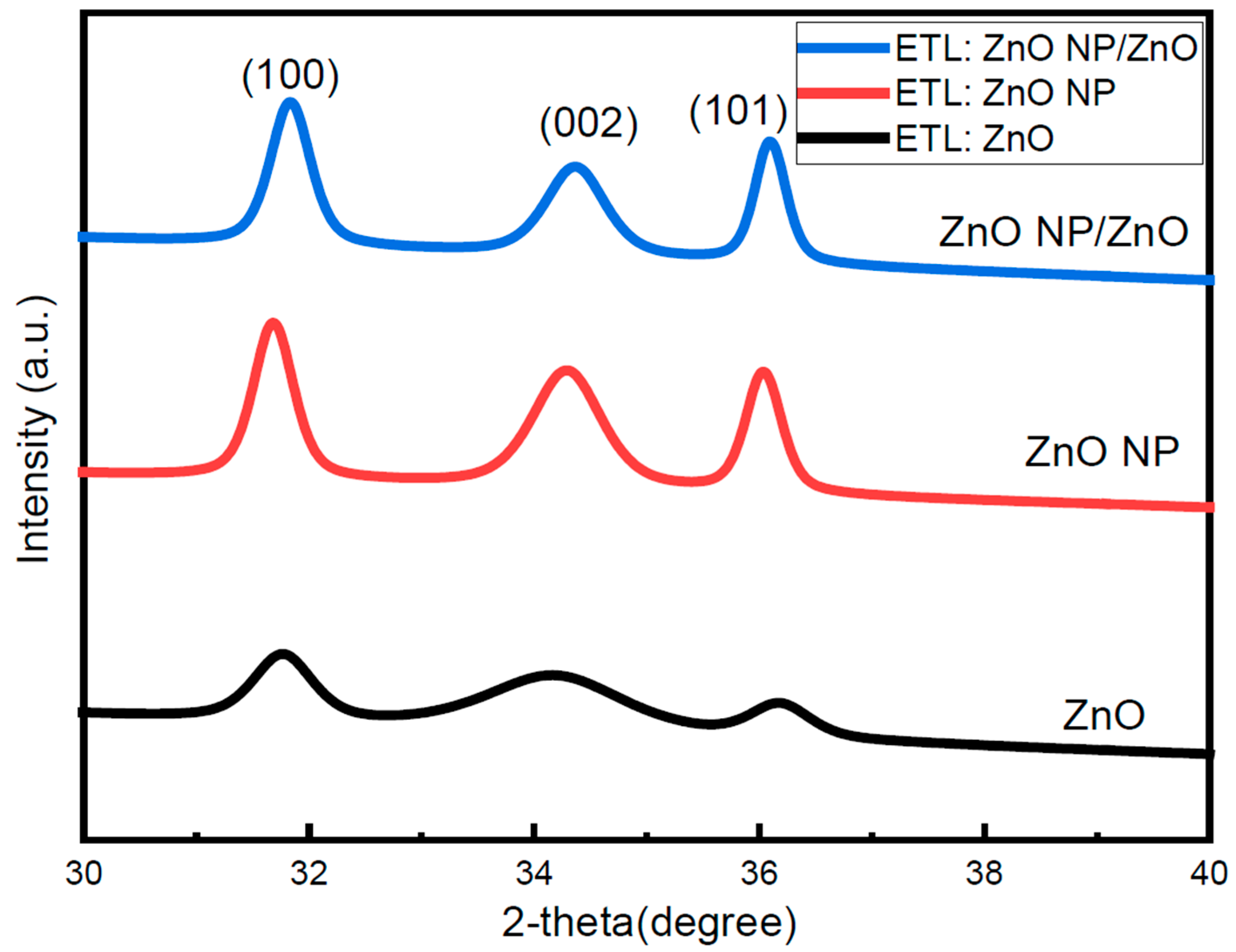
Figure 1. X-ray diffraction (XRD) patterns of ZnO, ZnO-NP, and bilayer ETL films on ITO glass substrate.
Nanomanufacturing 04 00006 g001
Figure 2. (a) Transmittance of ITO/ZnO and ITO/ZnO NP/ZnO films. (b) Absorbance spectra of ITO/ZnO and ITO/ZnO NP/ZnO films.
Nanomanufacturing 04 00006 g002
Figure 3. Atomic force microscopy (AFM) images of ETL films on top of ITO glass substrate: (a) ZnO, (b) ZnO NP, (c) ZnO NP/ZnO, (d) ZnO NP/ZnO/PTB7-Th:IEICO-4F, and (e) ZnO NP/ZnO/PM6:Y6.
Nanomanufacturing 04 00006 g003aNanomanufacturing 04 00006 g003b
Figure 4. Scanning electron microscopy (SEM) images of ETL films on top of ITO glass substrate: (a) ZnO, (b) ZnO NP, (c) ZnO NP/ZnO, and (d) cross-section of bilayer ZnO NP/ZnO.
Nanomanufacturing 04 00006 g004
Figure 5. (a) ZnO, (c) ZnO NP, and (e) ZnO NP/ZnO represent Zn 2p3 core label XPS spectra of ZnO, ZnO NP, and bilayer ZnO NP/ZnO ETL. Also, (b) ZnO, (d) ZnO NP, and (f) ZnO NP/ZnO show O1s core label XPS spectra of ZnO, ZnO NP, and bilayer ZnO NP/ZnO ETL.
Nanomanufacturing 04 00006 g005
Figure 6. (a) Schematic diagram of the inverted structure of non-fullerene OSCs, (b) chemical structures of donor materials and acceptor materials, (c) energy band diagrams of ZnO, IEICO-4F, PTB7-Th, Y6 and PM6, and (d) absorption spectra of ZnO NP/ZnO/PTB7-Th:IEICO-4F and ZnO NP/ZnO/PM6:Y6.
Nanomanufacturing 04 00006 g006
Figure 7. (a) J-V characteristics for PTB7-Th:IEICO-4F, (b) EQE spectra for PTB7-Th:IEICO-4F and (c) statistical distribution of PCE for PTB7-Th:IEICO-4F based devices with different ETLs. (d) J-V characteristics for PM6:Y6, (e) EQE spectra for PM6:Y6 and (f) statistical distribution of PCE for PM6:Y6-based devices with different ETLs.
Nanomanufacturing 04 00006 g007
Figure 8. Dark current–voltage characteristics for (a) PTB7-Th:IEICO-4F (black line shows dark JV with ZnO ETL and red line shows dark JV with ZnO NP/ZnO)- and (b) PM6:Y6-based devices (black line shows dark JV with ZnO ETL and blue line shows dark JV with ZnO NP/ZnO).
Nanomanufacturing 04 00006 g008
Figure 9. Nyquist plots at a bias of 600 mV under the dark condition for PTB7-Th:IEICO-4F- and PM6:Y6-based devices.
Nanomanufacturing 04 00006 g009
Figure 10. (a,b) Normalized PCE for PTB7-Th:IEICO-4F and PM6:Y6 based devices with different ETLs with time. (c,d) SEM images of fresh and aged bilayer ZnO NP/ZnO ETLs.
Nanomanufacturing 04 00006 g010aNanomanufacturing 04 00006 g010b
Table 1. Morphological parameters of different ETLs.
Electron Transport LayerRrms (nm)Average (nm)
ITO/ZnO5.818.96
ITO/ZnO NP9.2543.51
ITO/ZnO NP/ZnO4.7719.49
ITO/ZnO NP/ZnO/PTB7-Th:IEICO-4F1.786.37
ITO/ ZnO NP/ZnO/PM6:Y62.357.06
Table 2. Photovoltaic parameters for PTB7-Th:IEICO-4F and PM6:Y6 devices with ZnO and ZnO NP/ZnO ETL.
DevicesPCE (%)Voc (V)Jsc (mA/cm2)FF (%)Rsh (Ωcm−2)Rs (Ωcm−2)
ZnO/PTB7-Th:IEICO-4F9.180.7322.0856.29356.856.345
ZnO NP/ZnO/PTB7-Th:IEICO-4F10.20.7423.5558.29380.255.22
ZnO/PM6:Y613.950.8024.9269.3396634.69
ZnO NP/ZnO/PM6:Y614.60.8025.9769.631045.831.75
Disclaimer/Publisher’s Note: The statements, opinions and data contained in all publications are solely those of the individual author(s) and contributor(s) and not of MDPI and/or the editor(s). MDPI and/or the editor(s) disclaim responsibility for any injury to people or property resulting from any ideas, methods, instructions or products referred to in the content.