Article

Insights into the Electrocatalytic Activity of Mixed-Valence Mn3+/Mn4+ and Fe2+/Fe3+ Transition Metal Oxide Materials

1
National Institute for Research and Development in Electrochemistry and Condensed Matter Timisoara (INCEMC), 300569 Timisoara, Romania
2
Institute for Advanced Environmental Research, West University of Timisoara (ICAM-WUT), 300086 Timisoara, Romania
*
Author to whom correspondence should be addressed.
Solids 2025, 6(3), 48; https://doi.org/10.3390/solids6030048
Submission received: 10 July 2025 / Revised: 16 August 2025 / Accepted: 19 August 2025 / Published: 26 August 2025

Abstract

Hydrogen generation has become a popular research subject in light of currently pressing issues, such as the rapidly increasing environmental pollution, the depleting fossil fuel reserves, and the looming energy crisis. Sustainable electrochemical water splitting is regarded as one of the most desirable methods for obtaining green hydrogen. Considering this state of affairs, the water splitting electrocatalytic activity of glassy carbon electrodes modified with birnessite-type K2Mn4O8 and mixed-valence iron phosphate Fe3(PO3OH)4(H2O)4 materials were evaluated in electrolyte solutions having different pH values. Both compounds were characterized by X-ray diffraction and FT-IR spectroscopy in order to analyze their phase purity and their structural features. The most catalytically active birnessite-type K2Mn4O8-based electrode was manufactured using a catalyst ink containing only the electrocatalyst dispersed in ethanol and Nafion solution. In 0.1 M H2SO4, it exhibited an oxygen evolution reaction (OER) overpotential of 1.07 V and a hydrogen evolution reaction (HER) overpotential of 0.957 V. The Tafel slopes obtained in the OER and HER experiments were 0.180 and 0.142 V/dec, respectively. The most catalytically active mixed-valence iron phosphate Fe3(PO3OH)4(H2O)4-based electrode was obtained with a catalyst ink containing the specified material mixed with carbon black and dispersed in ethanol and Nafion solution. In a strongly alkaline medium, it displayed a HER overpotential of 0.515 V and a Tafel slope value of 0.122 V/dec. The two electrocatalysts have not been previously investigated in this way, and the acquired data provide insights into their electrocatalytic activity and improve the scientific understanding of their properties and applicative potential.

1. Introduction

Rapid economic development and population growth have led to the current socio-economic and environmental context, characterized by a daily increase in energy demand, a gradual exhaustion of fossil energy sources, and the constant worsening of the consequences of global warming and climate change [1]. The solution proposed by the scientific community to replace this undesired state of affairs with a far more acceptable one is focused on the development of clean, renewable, and sustainable energy, as well as on the restructuring of the energy industry to ensure an accelerated transition from the fossil fuel-oriented infrastructure to a renewable energy-based one [2,3]. Considering this background, hydrogen, while not a primary energy source, has emerged as a promising energy carrier with the potential to replace fossil fuels [4]. Out of the several known methods for obtaining hydrogen, sustainable electrocatalytic water splitting is regarded as one of the best strategies for the large-scale generation of high-purity H2 [5]. The hydrogen evolution reaction (HER) and the oxygen evolution reaction (OER) are the two half-cell reactions occurring during water electrolysis. The water reduction unfolds at the cathode, and the water oxidation takes place at the anode. Water decomposition by water electrolysis is significantly hindered due to the high overpotential value required to overcome the energy barrier of the reaction system. This is particularly the case with the OER, a multiple electron transfer process with slow reaction kinetics [6]. Presently, the benchmark electrocatalysts for the two half-cell reactions are carbon-supported platinum for the HER and iridium and ruthenium oxides for the OER [7]. Pt, Ru, and Ir are precious and scarce metals that make large-scale water electrolysis economically unfeasible. Substantial effort is being made to find suitable replacements for the aforementioned catalysts, based primarily on low-cost earth-abundant transition metals. Since manganese is one such metal, many Mn-based materials have been studied in terms of their electrochemical water splitting properties [8,9]. Water electrolysis by Mn-containing catalysts is a complex process dependent on structural, compositional, and morphological features, as well as on the electrolyte solution being used. The general mechanism involves charge transfer to the interface between the surface of the catalyst and the electrolyte solution, which leads to a decrease in the energy barrier for the OER and the HER. During the HER, H* is adsorbed and desorbed, and the reaction rate is determined by the material’s adsorption capacity to hydrogen [9]. The OER process is more complex and includes several stages, such as the formation of reactive oxygen species, the transfer of protons and electrons, and the release of oxygen gas [9].
Mn-based oxides can have several crystal forms, and the manganese ion is known to have several valence states that can be transformed into each other, promoting electrocatalytic activity enhancement via defect generation [8]. In addition, mixed-valence manganese oxides play important roles and have many promising applications in catalysis, electronics, sensors, etc. [10,11,12,13]. These materials are abundant and low-cost and have unique properties due to the different valence states of Mn cations: Mn3+, Mn4+, and Mn2+. For example, potassium-containing manganese oxide materials have been shown to display excellent catalytic performance in soot combustion, with high resistance to H2O and SO2 [14], and are promising cathodes for potassium ion batteries [15].
In this research work, the electrochemical water splitting properties of K2Mn4O8 were investigated in an acidic environment. The electrode manufactured with a catalyst ink containing the material dispersed in ethanol and Nafion solution exhibits electrocatalytic activity for both the HER and the OER.
Aside from manganese-based materials, water splitting studies have also been performed on phosphates. The reported investigations outline their high activity and stability for the HER and the OER [16,17,18]. Poienar et al. previously revealed the water splitting properties of Fe3(PO4)2(OH)2 iron phosphate materials [19]. To the best of the authors’ knowledge, no investigation has been published concerning the water electrolysis activity of mixed-valence iron phosphate Fe3(PO3OH)4(H2O)4 materials.
Herein, the electrochemical water decomposition activity of birnessite-type K2Mn4O8 and mixed-valence iron phosphate Fe3(PO3OH)4(H2O)4 materials was evaluated in electrolyte solutions having different pH values. The highest activity was observed in a strongly alkaline medium for the electrode modified with a catalyst ink containing the mixed-valence iron phosphate. It displayed a HER overpotential of 0.515 V and a Tafel slope of 0.122 V/dec.

2. Experimental Method

2.1. Materials and Reagents

The birnessite-type K2Mn4O8 and mixed-valence iron phosphate Fe3(PO3OH)4(H2O)4 materials were synthesized as follows. For the K2Mn4O8 materials, a rapid solid-state synthesis was used starting with the KMnO4 and Mn(CH3COO)2·4H2O reactants. They were mixed in an agate mortar for homogenization, resulting in ground fine powders. The mixture was transferred into an alumina crucible and heated in a muffle furnace to a temperature of 600 °C for 6 h. The obtained black-colored powder was recovered at the end of the thermal treatment and analyzed without any other preparation. The Fe3(PO3OH)4(H2O)4 materials were obtained as previously described in [20] by a hydrothermal method at low temperature and low pressure, starting with vivianite Fe3(PO4)2·8H2O and H3PO4, at 110 °C for 5 days. The yellow-colored powder obtained from the solution was filtered, washed with distilled water, and air-dried at 80 °C for 2 h.
The conductive supports modified with catalyst inks during the electrode manufacturing process consisted of glassy carbon (GC) pellets (from Andreescu Labor & Soft SRL, Bucharest, Romania) having a diameter of 8 mm. Vulcan XC 72 carbon black (Sigma Aldrich, Saint Louis, MO, USA) was used in the electrocatalytic process to enhance the charge transport and to diminish the clumping tendency of the catalyst particles. Nafion® 117 solution (Fuell Cell Store, Bryan, TX, USA) was used to prevent particle detachment from the GC surface during the water splitting and stability experiments. Sulfuric acid 98%, potassium chloride, and potassium hydroxide were procured from Merck (Darmstadt, Germany) and used to obtain the electrolyte solutions used during the electrochemical experiments. The catalyst inks were prepared with absolute ethanol (99.5%; ChimReactiv, Bucharest, Romania). All reagents were used as procured, and aqueous solutions were prepared with double-distilled water.

2.2. Electrode Manufacturing Method

The modified electrodes subjected to the electrochemical experiments were obtained with catalyst inks [21]. The electrode preparation method was based on protocols reported in the literature for obtaining modified electrodes with water splitting electrocatalytic properties [22,23].
The inks resulted from dispersing an amount of powder material in ethanol mixed with Nafion solution during a 30 min ultrasonication treatment. The powder material was the electrocatalyst—either the birnessite-type K2Mn4O8 material or the Fe3(PO3OH)4(H2O)4 material—by itself or combined with carbon black. A volume of 10 µL was taken from each catalyst ink and was drop-casted on the surface of the GC substrates. The modified electrodes were obtained after a drying stage at 40 °C. Table 1 shows the labels attributed to the studied electrodes and the compositions of the catalyst inks.

2.3. Electrochemical Study

The setup used to perform the electrochemical experiments consisted of a Voltalab potentiostat, model PGZ 402 (Radiometer Analytical, Lyon, France); a standard electrochemical glass cell; and three electrodes. The cell contained the electrolyte solution with the immersed electrodes being connected to the potentiostat. A Pt plate with a geometric surface (Sgeom) of 0.8 cm2 served as the counterelectrode. The Ag/AgCl (sat. KCl) electrode was used as a reference. Each of the electrodes from Table 1 was used as a working electrode after being positioned into a polyamide support to restrict the surface to Sgeom = 0.28 cm2. The water splitting experiments were performed in 0.1 M H2SO4 and 1 M KOH solutions. The solutions were deaerated with high-purity N2 before each HER experiment. The anodic and cathodic polarization curves, obtained during the HER and OER studies, were iR-corrected and recorded at a scan rate (v) of 5 mV/s. The values of the electrochemical potential (E) were represented with respect to the Reversible Hydrogen Electrode (RHE) using Equation (S1) from the Supplementary Material file [22]. Equations (S2)–(S7) were used to determine the values of the OER and HER overpotentials, the Tafel slope, the capacitive current density, the roughness factor, and the electrochemically active surface area (ECSA) of the electrodes [24,25,26].

2.4. Physical–Chemical Characterizations

X-ray powder diffraction data were collected at room temperature with a PANalyticalX’Pert PRO MPD Diffractometer (Malvern Panalytical, Malvern, UK) with Cu-Kα radiation (λ = 1.5418 Å) in the 2θ = 10–50° range.
A Schimadzu Prestige-21 FT-IR Spectrometer (Shimadzu, Kyoto, Japan) was used to carry out FT-IR spectrometry investigations, in KBr pellets, in the 500 to 4000 cm−1 range.
Raman spectra were recorded at room temperature with a MultiView-2000 system (Nanonics Imaging Ltd., Jerusalem, Israel) equipped with a Shamrock 500i spectrograph (Andor, Essex, UK) while using a 514 nm laser excitation.
SEM investigations were performed using the JEOL JSM IT200 equipment (JEOL, Freising, Germany).
AFM investigations were performed using a MultiView 2000 scanner (Nanonics Imaging Ltd., Jerusalem, Israel) in intermittent mode (radius tip = 20 nm).

3. Results and Discussion

3.1. Structural and Morphological Analysis of Birnessite-Type K2Mn4O8 Materials

The X-ray diffraction pattern for the K2Mn4O8 material powder sample, obtained as mentioned in Section 2.1, is shown in Figure 1a. It can be seen that the compound is well-crystallized, and the main peaks are indexed according to the JCPDS Card No 00-016-0205, corresponding to the K2Mn4O8 phase. Other, lower-intensity peaks are also present, marked with * in Figure 1a, and are indexed according to the MnO2 phases (JCPDS Card No 00-043-1455 and JCPDS Card No 01-072-1984). The obtained K2Mn4O8 or K0.5MnO2 compound crystallized in the birnessite-type structure, but the determination and clear description of the characteristic crystal structure for this compound has not been reported in the literature, i.e., no crystallographic information data file is available in the database. However, the general description of the birnessite structure can be given as layers of edge-sharing MnO6 octahedra (Mn3+ and Mn4+) and layers of cations, such as Na+, K+, Ca2+, Mg2+, and Mn2+. Water molecules are also intercalated between the layers, and the distances between these layers are approximatively 0.07 nm, making these compounds suitable for a large range of applications where mass transfer and ion exchange are essential [15,27]. Moreover, two types of structures are possible for birnessite layer symmetry [28]. The first structure type is an orthogonal structure composed of layers of [Mn4+O6], with or without minor vacancies, and [Mn3+O6] octahedra distorted along the same direction due to the cooperative Jahn–Teller effect. The second proposed structure is a hexagonal one, mainly composed of [Mn4+O6] with a large quantity of vacancies and [Mn3+O6] present in a small amount or absent.
The correlation between the K2Mn4O8 (or K0.5MnO2) structure and the P3-type structure of K0.48Mn0.94O2 (space group R-3m, JCPDS Card No 00-030-0950) has been previously made by Weng et al. [15]. The P3-type structure is characterized by layers of edge-sharing MnO6 octahedra separated by K ions in prismatic site configuration, while the oxygen atoms are present in an ABBCCA sequence along the stacking axis [29,30,31].
Raman spectra were recorded at room temperature in order to gain more insight into the crystal structure of the synthesized birnessite sample. Raman bands in manganese oxides are observed in two frequency intervals, 200–500 and 500–700 cm−1, and depend on the structural arrangement of the MnO6 octahedra, which can be edge-sharing or corner-sharing octahedra, elongated octahedra in the case of Mn3+ (due to Jahn–Teller distortion), or octahedra interacting with other cations present in the structure [32,33].
As can be seen in Figure 1b, there are two distinct bands in the 575–650 cm−1 region, with vibrations around 640 cm−1 corresponding to symmetric v2(Mn–O). According to the literature, the aforementioned bands correspond to birnessite-type manganese oxide [34]. In the region below 575 cm−1, smaller intensity bands are observed at ~300 and ~360 cm−1, which can be assigned to the Mn–O bending vibrations, while the band at 490 cm−1 corresponds to the v5(Mn–O) symmetric vibrations [35]. The signatures of the OH- bonds are visible on the spectrum at 1200 cm−1.
For other birnessite samples reported in the literature, the experimental results show four components located at 409, 498, 575, and 638 cm−1 [36] or three bands located at 514, 578, and 641 cm−1 [37]. The shift (variation) in the Raman bands associated with different birnessite samples could be related to the presence of vacancies in the [MnO2] layers, different layer sequences, distributions of heterovalent Mn, or distributions of interlayer K and vacant-layer octahedra [38].
The FT-IR spectrum for the birnessite-type K2Mn4O8 sample is shown in Figure 1c. The peaks characteristic to O–H and H–O–H are at 3393, 1648, 1629, and 1400 cm−1 [39]. The bands situated between 1056 and 833 cm−1 can be assigned to Mn(III)–OH and to –OH vibrations located at vacant Mn octahedral sites [39,40]. The bands situated at 517, 485, and 431 cm−1 are characteristic to Mn–O bonds [34].
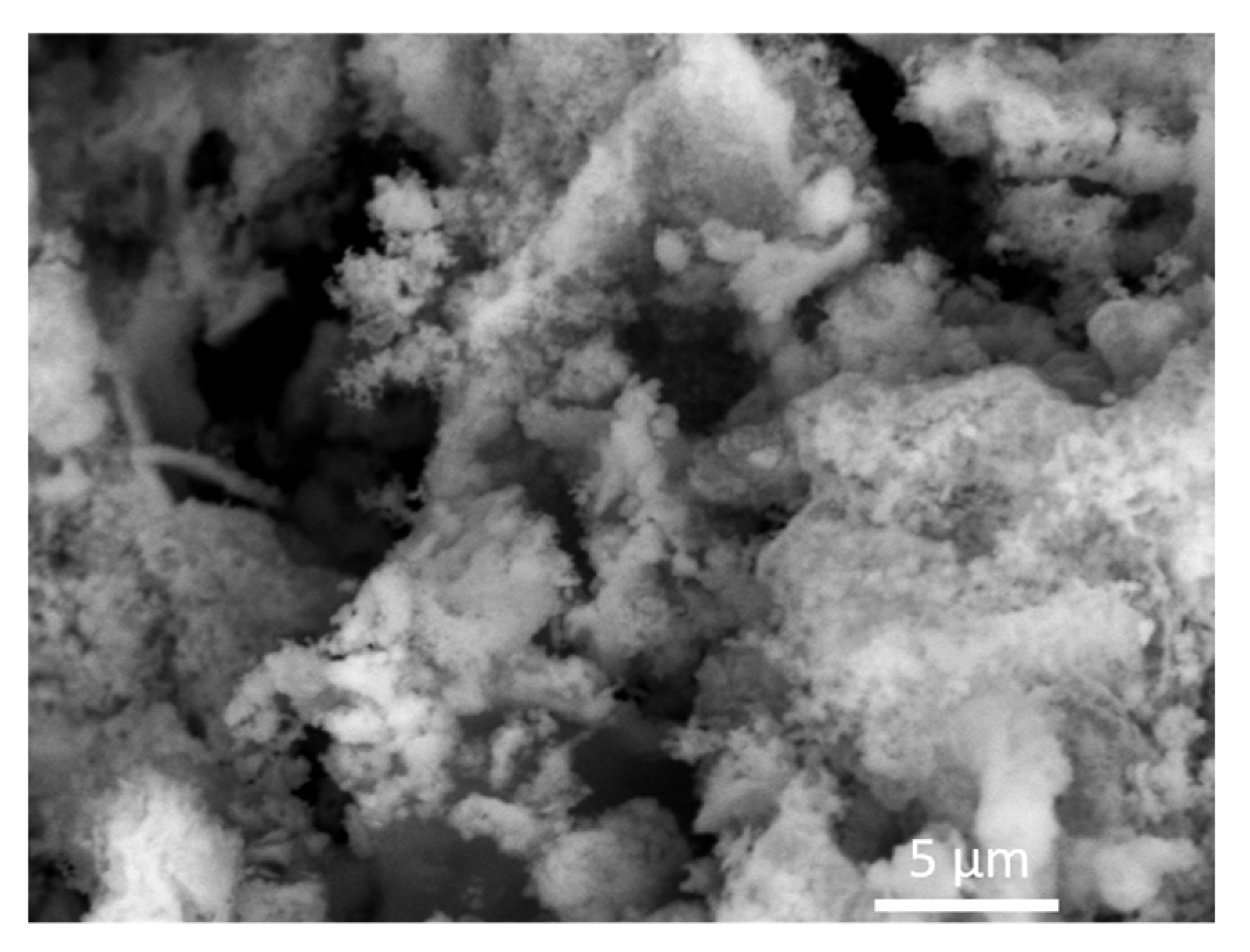
Figure 2 shows the morphology of the birnessite-type K2Mn4O8 sample. It can be seen that the compound is homogenous and contains particles of nanometric size, which are agglomerated into asymmetric formations.

3.2. Structural and Morphological Analysis of Mixed-Valence Iron Phosphate Fe3(PO3OH)4(H2O)4 Materials

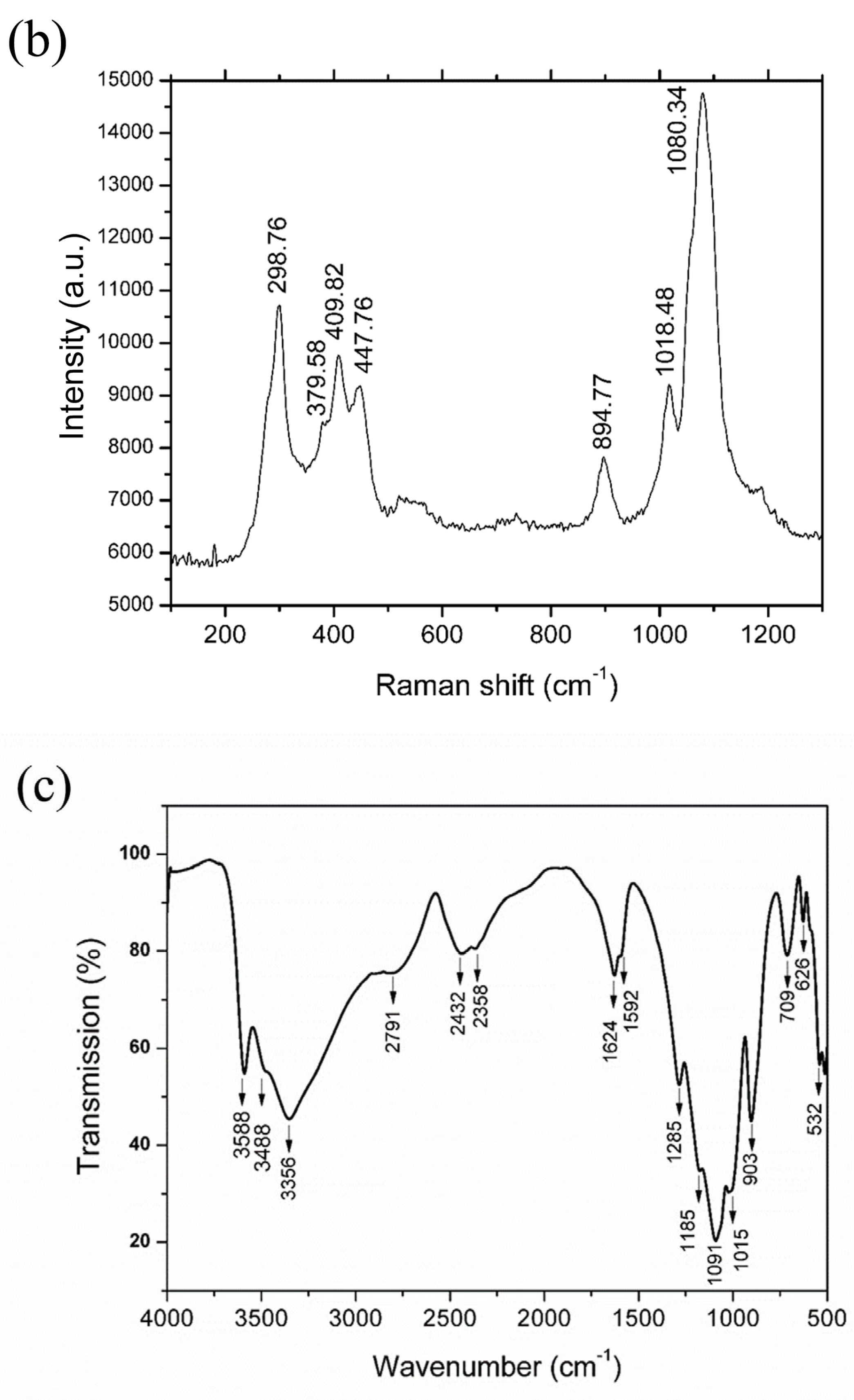
The same protocol was applied to investigate the structural characteristics of mixed-valence iron phosphate Fe3(PO3OH)4(H2O)4 materials: X-ray diffraction, Raman, and FT-IR spectra were obtained at room temperature. The X-ray diffraction pattern in Figure 3a shows that the compound crystallizes in the P21/n space group with the following lattice parameters: a = 8.7512(12) Å, b = 16.6203(29) Å, c = 5.1560(10) Å, and β = 90.865(14) Å [20,41]. The crystal structure of Fe3(PO3OH)4(H2O)4 consists of layers of Fe2+O6 octahedra alternating with wrinkled Fe3+O6 octahedra layers [20]. These FeO6 octahedra are linked by PO4 tetrahedra, and some of them have associated OH groups or H2O molecules.
Figure 3b shows the Raman spectrum obtained at room temperature. The following bands are observed in the 200–600 cm−1 range: 298.76, 379.58, 409.82, and 447.76 cm−1. In addition, the following bands are observed in the 800–1200 cm−1 range: 894.77, 1018.48, and 1080.34 cm−1. The peaks are located at 1018.48 and 1080.34 cm−1 (highest intensity) and are associated with the P–O stretching vibrations, as in the case of other iron phosphates, such as barbosalite Fe3(PO4)2(OH)2 [19]. The FeO stretching vibrations are located at 298.76 and 379.58 cm−1 [42], and the bands at 409.82 and 447.76 cm−1 are specific to PO4 and H2PO4 bending modes, respectively [43].
The FT-IR spectrum from Figure 3c was analyzed in correlation with the barbosalite Fe3(PO4)2(OH)2 materials [19], which allowed a deeper structural investigation of this material. As expected, the stretching vibrations of O–H in the 3300–3450 cm−1 range are visible at 3588, 3488, and 3356 cm−1, while the bands at 1624 and 1592 cm−1 are related to the chemically bonded H2O. The vibrations specific to mineral phosphates [44] and assigned to P–O stretching vibrations are between ~1100 and ~900 cm−1, as follows: 1185, 1091, 1015, and 903 cm−1. CO2 molecules adsorbed at the surface have specific bands at 2791, 2432, and 2358 cm−1. The bands at 532, 626, 709, 903, 1015, and 1091 cm−1 can be assigned to the vibration mode of O–P–O and P–OH bonds [42]. Also, in the 400–600 cm–1 range, bands corresponding to the Fe–O polyhedral environment are present [45].
The morphology of the mixed-valence iron phosphate Fe3(PO3OH)4(H2O)4 sample is presented in Figure 4. As previously mentioned in [20], the sample is characterized by needle-shaped particles with lengths varying from 50 to 200 μm and different widths (10–50 μm).

3.3. Electrochemical Study of K2Mn4O8-Based Electrodes

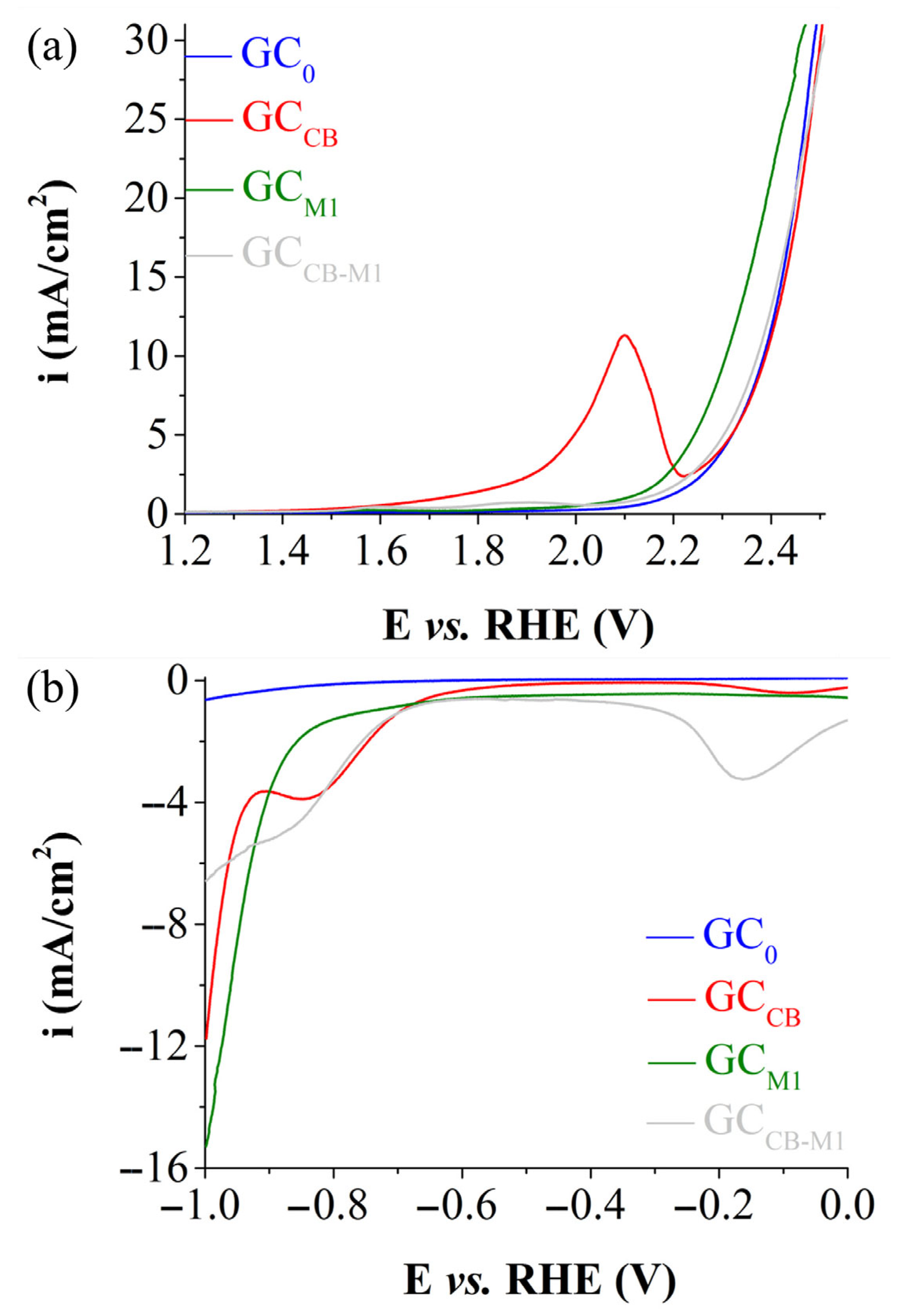
When tested in an alkaline medium (1 M KOH), the K2Mn4O8-based electrodes exhibit lower OER and HER electrocatalytic activity than the electrode modified only with carbon black. The linear sweep voltammograms (LSVs) recorded on the samples studied in the acidic medium (0.1 M H2SO4) are presented in Figure 5. Figure 5a shows the polarization curves obtained during the OER experiments, while the voltammograms traced in the HER investigations can be seen in Figure 5b. The HER and OER electrocatalytic activity of the GCM1 electrode is lower than the activities of the other studied samples. The electrode’s OER and HER overpotential values (ηOER and ηHER) are specified for the current densities of 10 mA/cm2 and −10 mA/cm2, respectively, in agreement with previously published studies [6,46]. The ηOER and ηHER values corresponding to i = 10 mA/cm2 and i = −10 mA/cm2 are 1.07 V and 0.957 V, respectively. This result indicates that K2Mn4O8 acts as a bifunctional electrocatalyst, able to catalyze both half-cell reactions unfolding in the process of electrochemical water splitting [47].
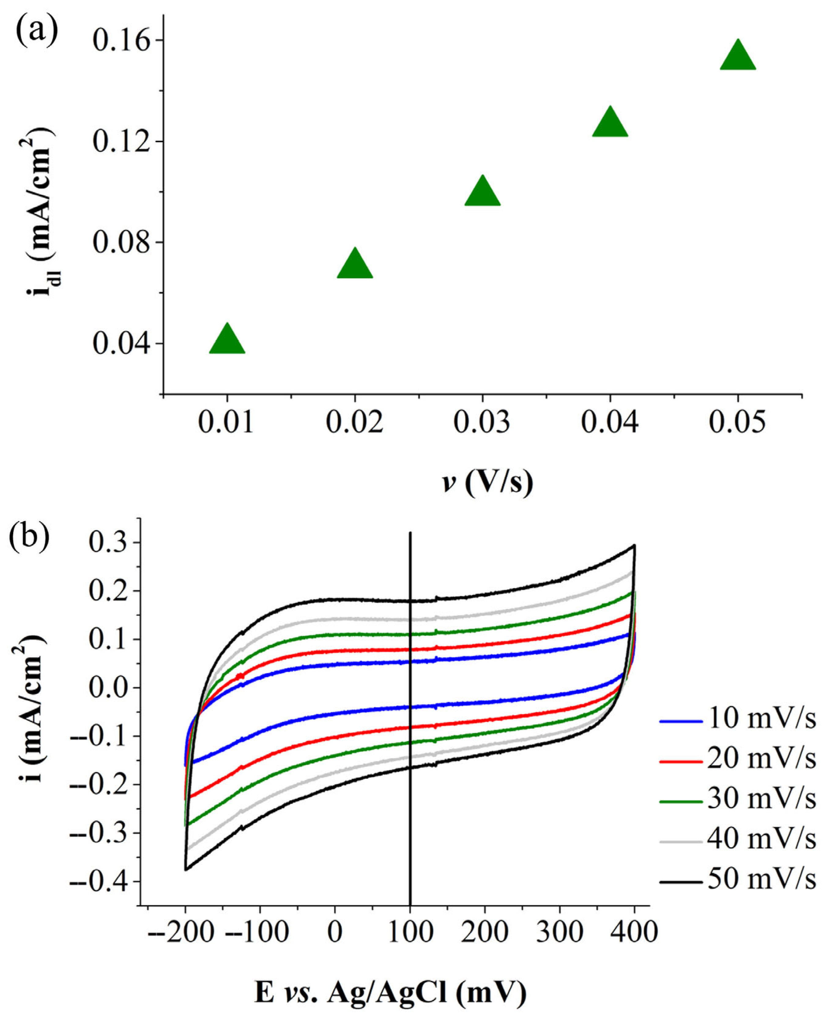
The ECSA of GCM1 was estimated based on the double-layer capacitance (Cdl). To obtain the value of the latter parameter, the capacitive current density (idl) was graphically represented as a function of the scan rate (Figure 6a). The idl values were calculated with Equation (S5) from the Supplementary Material file using the results from the recording of cyclic voltammograms on the modified electrode at increasing scan rate values (Figure 6b).
Table 2 shows the average Cdl value determined for two GCM1 electrodes and the corresponding R2 value; the roughness factor (Rf), which represents the ratio between the real and geometrical surfaces of an electrode and was calculated with Equation (S6) from the Supplementary Material file; and the estimated ECSA value.
The ECSA parameter is of importance to water splitting investigations because its value is directly proportional to the number of catalytic centers that are active at the electrode–electrolyte solution interface during water electrolysis and because it is involved in the study of the OER and HER kinetics [48,49,50]. Regarding the kinetics of the two half-cell reactions at the interface between GCM1 and the 0.1 M H2SO4 solution, Figure 7 shows the Tafel plots obtained using the anodic and cathodic LSVs recorded on the modified electrode. The Tafel slopes determined for the Tafel plots from Figure 7a,b are 0.180 V/dec (R2 = 0.9998) and 0.142 V/dec (R2 = 0.9993), respectively.

3.4. Electrochemical Study of Fe3(PO3OH)4(H2O)4-Based Electrodes

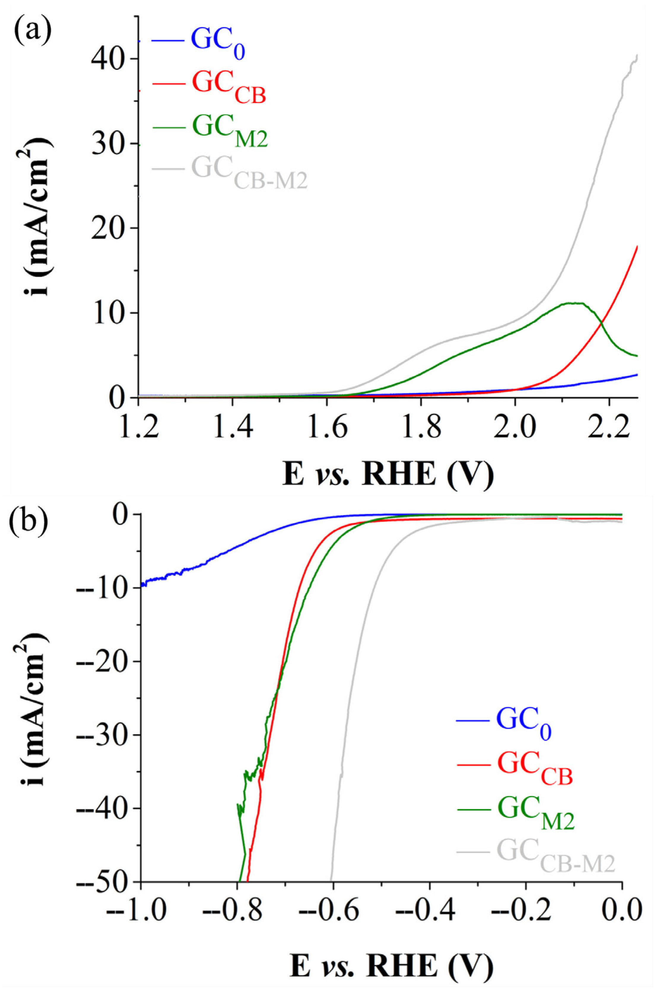
The LSVs recorded during the electrochemical experiments carried out on the Fe3(PO3OH)4(H2O)4-based electrodes in a strongly alkaline electrolyte solution, presented in Figure 8, reveal the GCCB-M2 electrode as the most electrocatalytically active one for both the OER (Figure 8a) and the HER (Figure 8b). The sample’s ηOER and ηHER values are 0.8 and 0.515 V, respectively. While the results indicate that mixed-valence iron phosphate Fe3(PO3OH)4(H2O)4 materials can behave as a bifunctional electrocatalyst, the ηOER value was too high to justify further OER investigation.
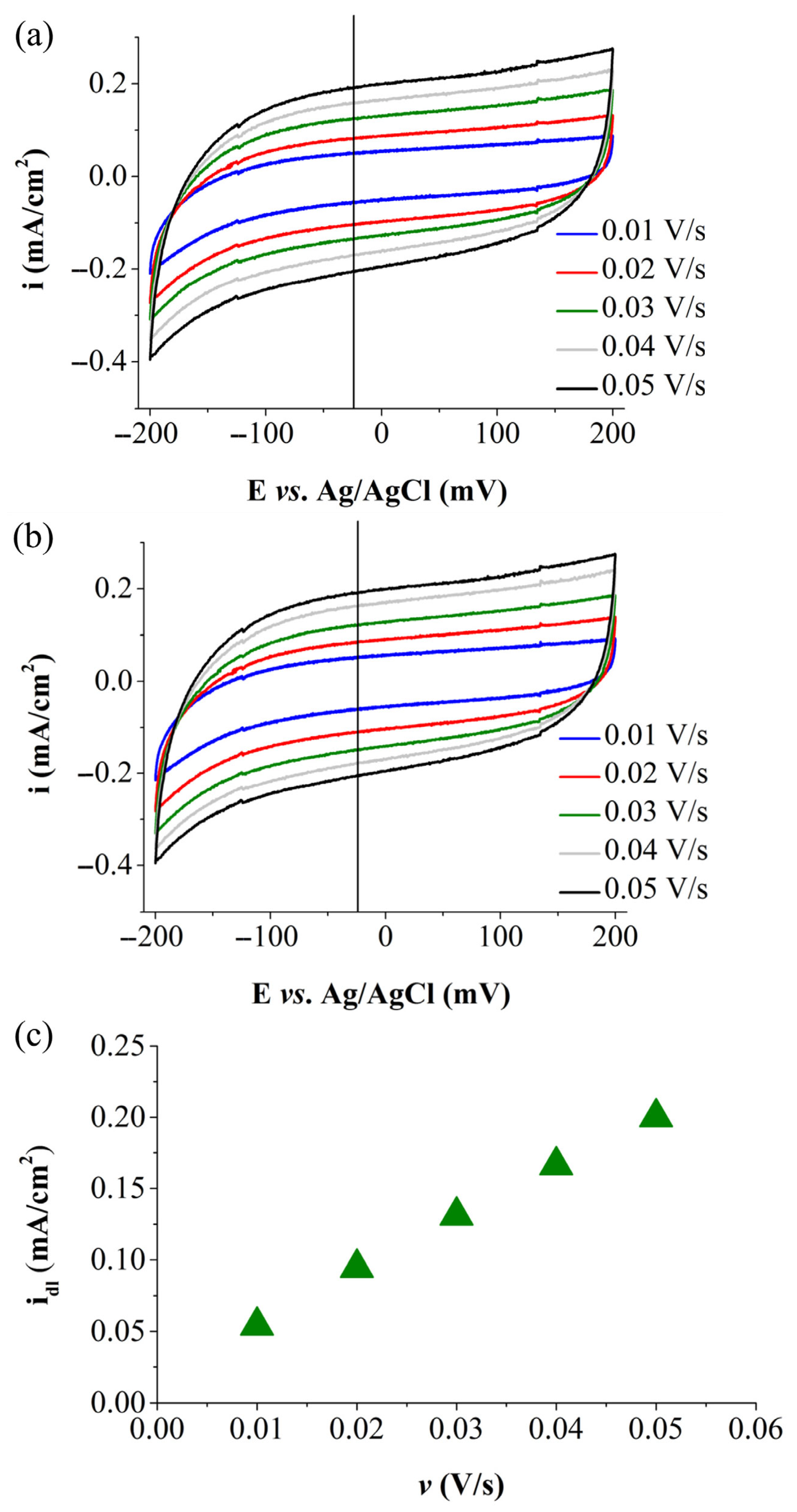
Figure 9a,b shows the cyclic polarization curves recorded on two GCCB-M2 electrodes. Figure 9c presents the plot of the average capacitive current density values determined with Equation (S5) from the Supplementary Material file and the voltammetry data from both samples vs. the scan rate. The Cdl value obtained from the plot in Figure 9c and the R2, Rf, and ECSA values determined for the GCCB-M2 electrode are shown in Table 3.
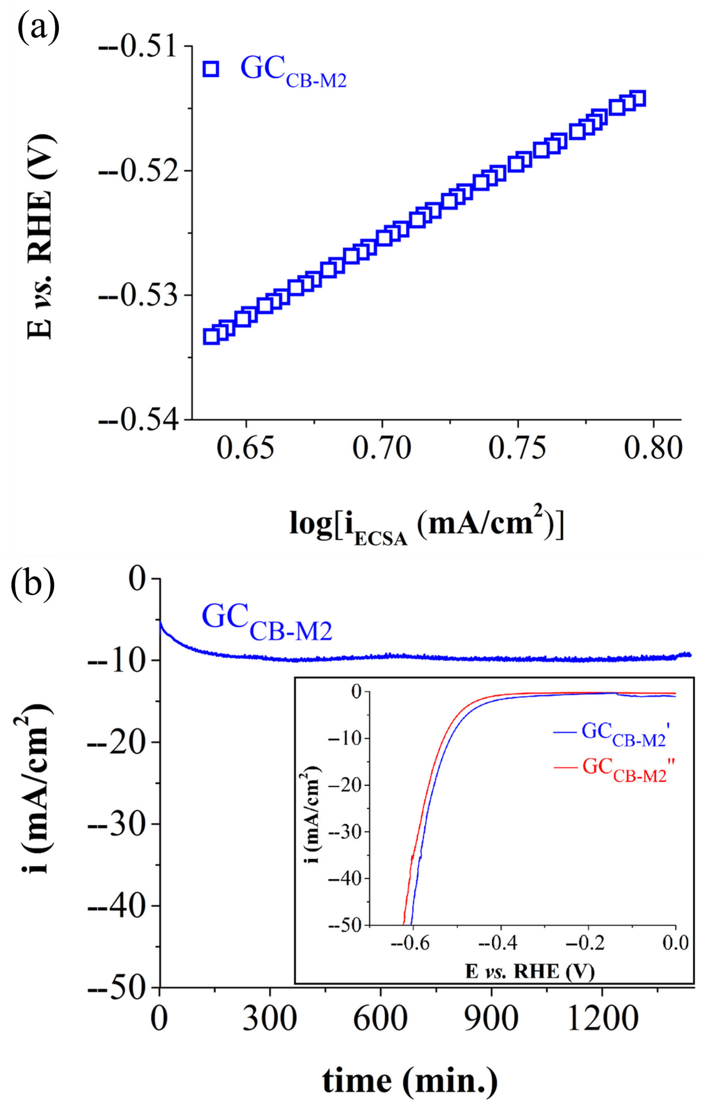
Concerning the HER kinetics at the interface between the electrode and the environment in which it was immersed, Figure 10a displays the Tafel plot obtained from the cathodic linear voltammogram recorded for GCCB-M2. A Tafel slope of 0.122 V/dec (R2 = 0.9998) was found. It should be noted that the HER kinetics involves three steps: Volmer, Heyrovsky, and Tafel. The first step is in a series with the two later ones, which are parallel to each other, indicating that the H2 evolution reaction involves two pathways, known as the Volmer–Heyrovsky and Volmer–Tafel mechanisms [51]. A Tafel slope between 0.04 and 0.12 V/dec points to a Volmer–Heyrovsky mechanism and a discharge step rate in line with that of the desorption step [52]. The determined value of 0.122 V/dec is close to the maximum one in the specified range, suggesting that for the GCCB-M2 electrode, the half-cell reaction occurs through the same pathway. Equations (1) and (2) describe the Volmer–Heyrovsky mechanism as it unfolds in an alkaline environment [53].
H2O + e → H* + OH
H* + H2O + e → OH + H2
The GCCB-M2 electrode was also studied regarding its electrochemical stability by being exposed to a constant E value for 24 h. The recorded chronoamperogram can be seen in Figure 10b, and it reveals the sample’s relatively high stability in the strongly alkaline electrolyte solution. To verify the impact of the testing on the electrocatalytic activity of the modified electrode, an anodic linear voltammogram was obtained after the experiment and overlapped with the polarization curve traced beforehand (inset in Figure 10b). After the testing, a ηHER increase of only 15 mV is observed at −10 mA/cm2, which further substantiates the stability of the electrocatalyst.
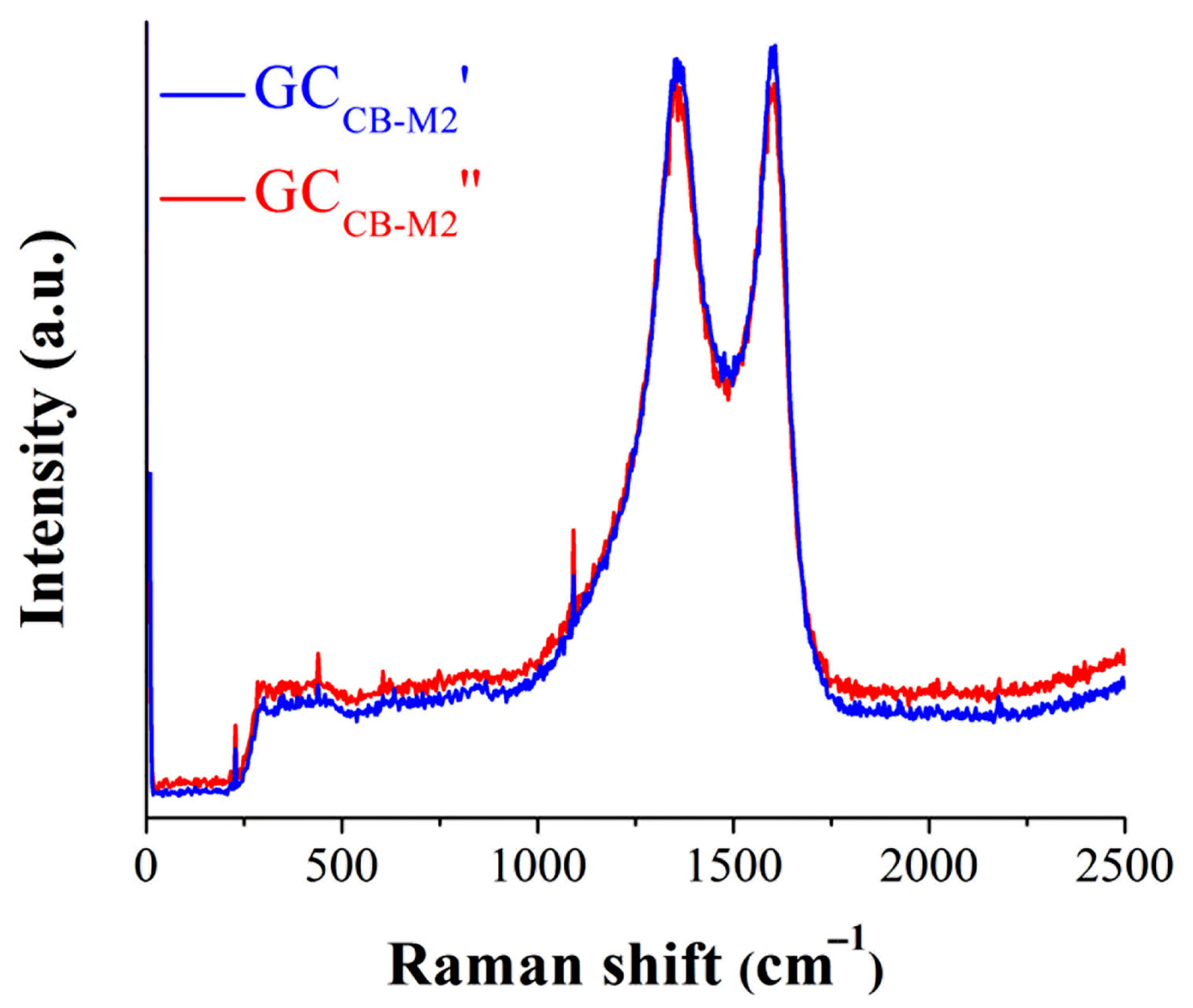
Raman spectroscopy was used to verify whether the electrocatalyst suffered any significant structural change during the chronoamperometric study. The spectra obtained before and after the test are shown in Figure 11. The most prominent peaks, corresponding to the carbon material, are located at 1358 cm−1 (D band—disorder-induced phonon mode) and 1601 cm−1 (G band—graphitic lattice mode E2g) [19,54]. The D band is an indicator for the defects in the graphitic structure associated with vacancies and grain boundaries as a result of the out-of-plane vibrations, while the G band is an indicator for the graphitic structure originating from the in-plane vibration of the sp2 C–C bond [55,56,57]. The shifts in the G band, broadening and/or overlapping, are suggestive of the presence of induced defects [58]. As mentioned by Dychalska et al., the position of the G band is a good indicator of whether the carbon species have a crystalline or amorphous structure [59]. The obtained results do not show any changes after the chronoamperometric experiment, since no shifts or modifications regarding the width of the bands are observed. The slight changes in peak intensities are attributed to the laser polarization, which may increase when it is parallel to the in-plane vibrational modes [60]. The peak observed at 1091 cm−1 can be attributed to the intramolecular antisymmetric stretching vibrations of the PO43− anions (ν3) specific to FePO4 [61,62]. Furthermore, the narrow shape of the band outlines the compound’s crystalline structure, which was not altered following the electrochemical stability test [63]. It is concluded that the material did not undergo any significant structural changes.
AFM analysis was performed to evaluate the morphology and dispersion of the active components of the Fe3(PO3OH)4(H2O)4-modified electrode (GCCB-M2), both before (GCCB-M2′) and after (GCCB-M2″) the chronoamperometric experiment. The results are presented in the Supplementary Material file (Figures S1–S3) and indicate that the deposited materials do not show any significant morphological changes following the electrochemical stability test. Furthermore, Table S2 shows the calculated values of the AFM parameters obtained based on the AFM analysis.
The values of the electrochemical parameters determined for the GCM1 electrode, studied in 0.1 M H2SO4 solution, and the GCCB-M2 electrode, studied in 1 M KOH solution, have all been included in Table 4 to facilitate a comparison between them. It can be seen that GCCB-M2 displays the lowest overpotential and Tafel slope values during the HER experiments. Furthermore, the highest ECSA value was calculated for the same electrode. Based on these results, it is concluded that out of the two investigated electrodes, GCCB-M2 shows greater promise of finding application in the water splitting domain.
Table S1 presents the ηHER and Tafel slope values obtained for GCCB-M2 and for other electrodes reported in the scientific literature for which at least one of the two values is comparable. This table lists 24 electrodes reported in the literature. For 18 of them, the Tafel slope has a higher value than the one found for GCCB-M2. Another 4 electrodes show comparable values. Regarding the ηHER, out of the 24 electrodes, 11 exhibit a higher value than GCCB-M2, 1 shows a comparable overpotential, and the 0.515 V value calculated for GCCB-M2 is also reported for the electrode based on a hybrid cobalt phthalocyanine polymer. However, a comparison between GCCB-M2 and reported electrodes modified with electrocatalysts for the HER in general has also been performed, and several review articles have been considered for this purpose [64,65,66,67,68,69,70]. The data indicate that the values of both electrocatalytic activity parameters are among the highest specified in the respective reviews. If the electrocatalyst is to find application in the water splitting domain, more advanced electrode manufacturing protocols may be required than the simple one used in this study. Lastly, since the investigated complex is a mixed-valence iron phosphate, it is pertinent to compare its water splitting catalytic activity to other materials from the same class. In a study reported by Poienar et al. [19], the water splitting electrocatalytic properties of laboratory-synthesized barbosalite—Fe3(PO4)2(OH)2—were evaluated by obtaining barbosalite-modified graphite electrodes. The HER experiments carried out in 1 M KOH electrolyte solution reveal a ηHER value of 0.3 V (at i = −10 mA/cm2) and a Tafel slope of 0.252 V/dec. While GCCB-M2 displays a higher overpotential value, the determined Tafel slope is less than twice the value found for the barbosalite-based electrode, indicating faster reaction kinetics.

4. Conclusions

The water splitting electrocatalytic activity of birnessite-type K2Mn4O8 materials was studied in an acidic environment, and the results reveal their bifunctional nature. The electrode labeled GCM1 displays the highest OER and HER activity in the specified medium. Regarding overpotential, its ηOER at i = 10 mA/cm2 is 1.07 V, and its ηHER at i = −10 mA/cm2 is 0.957 V. The Tafel slopes determined during the OER and HER investigations are 0.180 and 0.142 V/dec, respectively.
The water electrolysis activity of mixed-valence iron phosphate Fe3(PO3OH)4(H2O)4 materials was investigated in a strongly alkaline medium. The results show that the most electrocatalytically active electrode is the electrode labeled GCCB-M2, obtained by drop-casting on the surface of a GC substrate a catalyst ink containing the electrocatalyst mixed with carbon black. At i = −10 mA/cm2, it exhibits a ηHER value of 0.515 V, and the Tafel slope value determined during the HER investigation is 0.122 V/dec.
The two electrocatalysts have not been previously reported as having been studied in terms of their electrocatalytic water splitting activity. The data acquired during the water splitting studies provide insights into the electrocatalytic activity of birnessite-type K2Mn4O8 and mixed-valence iron phosphate Fe3(PO3OH)4(H2O)4 materials and improve the scientific understanding of their properties and applicative potential.

Supplementary Materials

The following supporting information can be downloaded at https://www.mdpi.com/article/10.3390/solids6030048/s1: Table S1. The HER activity of GCCB-M2 and of other electrodes reported in the scientific literature, in 1 M KOH solution. The ηHER values are read at i = −10 mA/cm2. Figure S1. (a) AFM image recorded on the GCCB-M2 electrode before the stability test. (b) AFM image recorded on the GCCB-M2 electrode after the stability test. Figure S2. Profile images obtained of selected areas of the surface of the GCCB-M2 electrode before the stability test. Figure S3. Profile images obtained of selected areas of the surface of the GCCB-M2 electrode after the stability test. Table S2. AFM parameter values. References [19,24,25,26,71,72,73,74,75,76,77,78,79,80,81] are cited in the Supplementary Material file.

Author Contributions

Conceptualization, M.P. and B.-O.T.; methodology, M.P. and B.-O.T.; validation, M.P. and B.-O.T.; formal analysis, M.P., P.S., G.B. and B.-O.T.; investigation, M.P., P.S., G.B. and B.-O.T.; writing—original draft preparation, M.P., P.S. and B.-O.T.; writing—review and editing, M.P., P.S., G.B. and B.-O.T.; supervision, M.P. All authors have read and agreed to the published version of the manuscript.

Funding

This research received no external funding.

Data Availability Statement

The original contributions presented in this study are included in the article/Supplementary Material file. Further inquiries can be directed to the corresponding author.

Acknowledgments

We thank Zoltan Szabadai and Florina Stefania Rus from INCEMC Timisoara for FT-IR and Raman measurements and Alexandru Pahomi from ICAM UVT for SEM images.

Conflicts of Interest

The authors declare no conflicts of interest.

References

  1. Holechek, J.L.; Geli, H.M.E.; Sawalhah, M.N.; Valdez, R. A global assessment: Can renewable energy replace fossil fuels by 2050? Sustainability 2022, 14, 4792. [Google Scholar] [CrossRef]
  2. Jaiswal, K.K.; Chowdhury, C.R.; Yadav, D.; Verma, R.; Dutta, S.; Jaiswal, K.S.; Sangmesh, B.; Karuppasamy, K.S.K. Renewable and sustainable clean energy development and impact on social, economic, and environmental health. Energy Nexus 2022, 7, 100118. [Google Scholar] [CrossRef]
  3. de Lange, D.E. Climate action now: Energy industry restructuring to accelerate the renewable energy transition. J. Clean. Prod. 2024, 443, 141018. [Google Scholar] [CrossRef]
  4. Reda, B.; Elzamar, A.A.; AlFazzani, S.; Ezzat, S.M. Green hydrogen as a source of renewable energy: A step towards sustainability, an overview. Environ. Dev. Sustain. 2024, 1–21. [Google Scholar] [CrossRef]
  5. Xu, Z.; Wu, Z.-S. Scalable production of high-performance electrocatalysts for electrochemical water splitting at large current densities. eScience 2024, 5, 100334. [Google Scholar] [CrossRef]
  6. Raveendran, A.; Chandran, M.; Dhanusuraman, R. A comprehensive review on the electrochemical parameters and recent material development of electrochemical water splitting electrocatalysts. RSC Adv. 2023, 13, 3843–3876. [Google Scholar] [CrossRef] [PubMed]
  7. Araujo, H.; Sljukic, B.; Gago, S.; Santos, D.M.F. The current state of transition metal-based electrocatalysts (oxides, alloys, POMs, and MOFs) for oxygen reduction, oxygen evolution, and hydrogen evolution reactions. Front. Energy Res. 2024, 12, 1373522. [Google Scholar] [CrossRef]
  8. Wang, H.; Yang, Y.; Liu, J.; Wu, H.; Wu, K.; Lyu, C.; Wu, J.; Lau, W.-M.; Wu, Q.; Zheng, J. The role of manganese-based catalyst in electrocatalytic water splitting: Recent research and progress. Mater. Today Phys. 2023, 36, 101169. [Google Scholar] [CrossRef]
  9. Hu, J.; Zhou, Y.; Liu, Y.; Xu, Z.; Li, H. Recent Advances in Manganese-Based Materials for Electrolytic Water Splitting. Int. J. Mol. Sci. 2023, 24, 6861. [Google Scholar] [CrossRef]
  10. Dutta, B.; Clarke, R.; Raman, S.; Shaffer, T.D.; Achola, L.; Nandi, P.; Suib, S.L. Lithium promoted mesoporous manganese oxide catalyzed oxidation of allyl ethers. Nat. Commun. 2019, 10, 655. [Google Scholar] [CrossRef]
  11. Zhang, B.; Zhang, J.; Shi, J.; Tan, D.; Liu, L.; Zhang, F.; Lu, C.; Su, Z.; Tan, X.; Cheng, X.; et al. Manganese acting as a high-performance heterogeneous electrocatalyst in carbon dioxide reduction. Nat. Commun. 2019, 10, 2980. [Google Scholar] [CrossRef]
  12. Lin, B.; Zhu, X.; Fang, L.; Liu, X.; Li, S.; Zhai, T.; Xue, L.; Guo, Q.; Xu, J.; Xia, H. Birnessite Nanosheet Arrays with High K Content as a High-Capacity and Ultrastable Cathode for K-Ion Batteries. Adv. Mater. 2019, 31, 1900060. [Google Scholar] [CrossRef]
  13. Zhao, H.; Li, H.; Pan, Z.; Feng, F.; Gu, Y.; Du, J.; Zhao, Y. Design of CeMnCu ternary mixed oxides as soot combustion catalysts based on optimized Ce/Mn and Mn/Cu ratios in binary mixed oxides. Appl. Catal. B Environ. 2020, 268, 118422. [Google Scholar] [CrossRef]
  14. Yu, D.; Ren, Y.; Yu, X.; Fan, X.; Wang, L.; Wang, R.; Zhao, Z.; Cheng, K.; Chen, Y.; Sojka, Z.; et al. Facile synthesis of birnessite-type K2Mn4O8 and cryptomelane-type K2−xMn8O16 catalysts and their excellent catalytic performance for soot combustion with high resistance to H2O and SO2. Appl. Catal. B Environ. 2021, 285, 119779. [Google Scholar] [CrossRef]
  15. Weng, J.; Duan, J.; Sun, C.; Liu, P.; Li, A.; Zhou, P.; Zhou, J. Construction of hierarchical K0.7Mn0.7Mg0.3O2 microparticles as high capacity & long cycle life cathode materials for low-cost potassium-ion batteries. Chem. Eng. J. 2020, 392, 123649. [Google Scholar] [CrossRef]
  16. Guo, R.; Lai, X.; Huang, J.; Du, X.; Yan, Y.; Sun, Y.; Zou, G.; Xiong, J. Phosphate-based electrocatalysts for water splitting: Recent progress. ChemElectroChem 2018, 5, 3822–3834. [Google Scholar] [CrossRef]
  17. Kim, C.; Lee, S.; Kim, S.H.; Park, J.; Kim, S.; Kwon, S.-H.; Bae, J.-S.; Park, Y.S.; Kim, Y. Cobalt–iron–phosphate hydrogen evolution reaction electrocatalyst for solar-driven alkaline seawater electrolyzer. Nanomaterials 2021, 11, 2989. [Google Scholar] [CrossRef] [PubMed]
  18. Krishnamurthy, P.; Maiyalagan, T. Phosphorus-doped cobalt sulphide nanocubes as an electrocatalyst for the hydrogen evolution reaction in an alkaline medium. New J. Chem. 2025, 49, 3997–4006. [Google Scholar] [CrossRef]
  19. Poienar, M.; Taranu, B.-O.; Svera, P.; Sfirloaga, P.; Vlazan, P. Disclosing the thermal behaviour, electrochemical and optical properties of synthetic Fe3(PO4)2(OH)2 materials. J. Therm. Anal. Calorim. 2022, 147, 11839–11855. [Google Scholar] [CrossRef]
  20. Poienar, M.; Gutmann, M.J.; Pascut, G.L.; Petrícek, V.; Stenning, G.; Vlazan, P.; Sfirloaga, P.; Paulmann, C.; Tolkiehn, M.; Manuel, P.; et al. Phase Transitions and Physical Properties of the Mixed Valence Iron Phosphate Fe3(PO3OH)4(H2O)4. Materials 2022, 15, 8059. [Google Scholar] [CrossRef]
  21. Taranu, B.-O.; Rus, F.S.; Fagadar-Cosma, E. A3B Zn(II)-porphyrin-coated carbon electrodes obtained using different procedures and tested for water electrolysis. Coatings 2024, 14, 1048. [Google Scholar] [CrossRef]
  22. Sfirloaga, P.; Bognár, S.; Taranu, B.-O.; Vlazan, P.; Poienar, M.; Merkulov, D.Š. Co- and Sn-doped YMnO3 perovskites for electrocatalytic water-splitting and photocatalytic pollutant degradation. Coatings 2025, 15, 475. [Google Scholar] [CrossRef]
  23. Chang, J.; Lv, Q.; Li, G.; Ge, J.; Liu, C.; Xing, W. Core-shell structured Ni12P5/Ni3(PO4)2 hollow spheres as difunctional and efficient electrocatalysts for overall water electrolysis. Appl. Catal. B Environ. 2017, 204, 486–496. [Google Scholar] [CrossRef]
  24. Taranu, B.-O.; Fagadar-Cosma, E. The pH influence on the water-splitting electrocatalytic activity of graphite electrodes modified with symmetrically substituted metalloporphyrins. Nanomaterials 2022, 12, 3788. [Google Scholar] [CrossRef]
  25. Ciriaco, M.L.F.; Silva-Pereira, M.I.; Nunes, M.R.; Costa, F.M. Electrochemical behaviour of BaSn0.9Sb0.1O3 coated titanium electrodes. Port. Electrochim. Acta 1999, 17, 149–156. [Google Scholar] [CrossRef]
  26. Taranu, B.-O. Different electrode modification protocols for evaluating the water-splitting properties of a P(V)-metalloporphyrin. J. Serbian Chem. Soc. 2025, 90, 447–459. [Google Scholar] [CrossRef]
  27. Hao, S.-M.; Qu, J.; Yang, J.; Gui, C.-X.; Wang, Q.-Q.; Li, Q.-J.; Li, X.; Yu, Z.-Z. K2Mn4O8/Reduced Graphene Oxide Nanocomposites for Excellent Lithium Storage and Adsorption of Lead Ions. Chem. Eur. J. 2016, 22, 3397–3404. [Google Scholar] [CrossRef]
  28. Yin, H.; Liu, Y.; Koopal, L.K.; Feng, X.; Chu, S.; Zhu, M.; Liu, F. High Co-doping promotes the transition of birnessite layer symmetry from orthogonal to hexagonal. Chem. Geol. 2015, 410, 12–20. [Google Scholar] [CrossRef]
  29. Liu, C.; Luo, S.; Huang, H.; Zhai, Y.; Wang, Z. Layered potassium-deficient P2- and P3-type cathode materials KxMnO2 for K-ion batteries. Chem. Eng. J. 2019, 356, 53–59. [Google Scholar] [CrossRef]
  30. Hironaka, Y.; Kubota, K.; Komaba, S. P2- and P3-KxCoO2 as an electrochemical potassium intercalation host. Chem. Commun. 2017, 53, 3693–3696. [Google Scholar] [CrossRef]
  31. Kim, H.; Seo, D.-H.; Kim, J.C.; Bo, S.-H.; Liu, L.; Shi, T.; Cede, G. Investigation of Potassium Storage in Layered P3-Type K0.5MnO2 Cathode. Adv. Mater. 2017, 29, 1702480. [Google Scholar] [CrossRef] [PubMed]
  32. Julien, C.; Massot, M.; Baddour-Hadjean, R.; Franger, S.; Bach, S.; Pereira-Ramos, J.-P. Raman spectra of birnessite manganese dioxides. Solid State Ionics 2003, 159, 345. [Google Scholar] [CrossRef]
  33. Julien, C.; Massot, M. Spectroscopic studies of the local structure in positive electrodes for lithium batteries. Phys. Chem. Chem. Phys. 2002, 4, 4226. [Google Scholar] [CrossRef]
  34. Peng, Y.; Zhang, F.; Huang, X.; Li, B.; Guan, G.; Zhang, W.; Zou, R.; Lu, X.; Hu, J. Hydrophilic K2Mn4O8 nanoflowers as a sensitive photothermal theragnosis synergistic platform for the ablation of cancer. New J. Chem. 2018, 42, 3714–3721. [Google Scholar] [CrossRef]
  35. Liu, Y.; Yan, D.; Zhuo, R.; Li, S.; Wu, Z.; Wang, J.; Ren, P.; Yan, P.; Geng, Z. Design, hydrothermal synthesis and electrochemical properties of porous birnessite-type manganese dioxide nanosheets on graphene as a hybrid material for supercapacitors. J. Power Sources 2013, 242, 78–85. [Google Scholar] [CrossRef]
  36. Ogata, A.; Komaba, S.; Baddour-Hadjean, R.; Pereira-Ramos, J.-P.; Kumagai, N. Doping effects on structure and electrode performance of K-birnessite-type manganese dioxides for rechargeable lithium battery. Electrochim. Acta 2008, 53, 3084–3093. [Google Scholar] [CrossRef]
  37. Ren, G.; Sun, M.; Sun, Y.; Li, Y.; Wang, C.; Lu, A.; Ding, H. A cost-effective birnessite–silicon solar cell hybrid system with enhanced performance for dye decolorization. RSC Adv. 2017, 7, 47975. [Google Scholar] [CrossRef]
  38. Gailloot, A.-C.; Flot, D.; Drits, V.A.; Manceau, A.; Burghammer, M.; Lanson, B. Structure of Synthetic K-rich Birnessite Obtained by High-Temperature Decomposition of KMnO4. I. Two-Layer Polytype from 800 °C Experiment. Chem. Mater. 2003, 15, 4666–4678. [Google Scholar] [CrossRef]
  39. Zhang, Y.; Tao, F.; Cao, S.; Yin, K.; Chang, X.; Fan, R.; Fan, C.; Dong, L.; Yin, Y.; Chen, X. Hierarchical K2Mn4O8 nanoflowers: A novel photothermal conversion material for efficient solar vapor generation. Sol. Energy Mater. Sol. Cells 2019, 200, 110043. [Google Scholar] [CrossRef]
  40. Martinez-Alonso, S.; Rustad, J.R.; Goetz, A.F.H. Ab initio quantum mechanical modeling of infrared vibrational frequencies of the OH group in dioctahedral phyllosilicates. Part II: Main physical factors governing the OH vibrations. Am. Mineral. 2002, 87, 1224. [Google Scholar] [CrossRef]
  41. Vencato, I.; Mascarenhas, Y.P.; Mattievich, E. The crystal structure of FeFe2(PO3OH)4(H2O)4: A new synthetic compound of mineralogic interest. Am. Mineral. 1986, 71, 222. [Google Scholar]
  42. Frost, R.L.; Xi, Y.; Lopez, A.; Scholz, R.; de Carvalho Lana, C.; de Souza, B.F. Vibrational spectroscopic characterization of the phosphate mineral barbosalite Fe2+Fe23+(PO4)2(OH)2—Implications for the molecular structure. J. Mol. Struct. 2013, 1051, 292–298. [Google Scholar] [CrossRef]
  43. Battle, P.D.; Cheetham, A.K.; Gleitzer, C.; Harrison, W.T.; Long, G.J.; Longworth, G. A novel magnetic phase transition in anhydrous iron(III) phosphate, FePO4. J. Phys. C Solid State Phys. 1982, 15, L919–L924. [Google Scholar] [CrossRef]
  44. Povarennykh, A.S. The use of infrared spectra for the determination of minerals. Am. Miner. 1978, 63, 956–959. [Google Scholar]
  45. Chukanov, N.V.; Chervonnyi, A.D. Infrared Spectroscopy of Minerals and Related Compounds; Springer International Publishing: Cham, Switzerland, 2016. [Google Scholar]
  46. Hou, W.; Zhou, C.; Li, Q.; Zhou, H.; Liu, Z.; Yang, L.; Wu, C.; Zhao, H.; Dong, S. Preparation and overall water-splitting performance study of amorphous nickel-copper-phosphide. J. Alloys Compd. 2024, 1002, 175314. [Google Scholar] [CrossRef]
  47. Aralekallu, S.; Lokesh, K.S.; Singh, V. Advanced bifunctional catalysts for energy production by electrolysis of earth-abundant water. Fuel 2024, 357 Pt A, 129753. [Google Scholar] [CrossRef]
  48. Taranu, B.-O.; Fagadar-Cosma, E.; Sfirloaga, P.; Poienar, M. Free-base porphyrin aggregates combined with nickel phosphite for enhanced alkaline hydrogen evolution. Energies 2023, 16, 1212. [Google Scholar] [CrossRef]
  49. Taranu, B.-O.; Vlazan, P.; Svera, P.; Poienar, M.; Sfirloaga, P. New functional hybrid materials based on clay minerals for enhanced electrocatalytic activity. J. Alloys Compd. 2022, 892, 162239. [Google Scholar] [CrossRef]
  50. Poienar, M.; Svera, P.; Taranu, B.-O.; Ianasi, C.; Sfirloaga, P.; Buse, G.; Veber, P.; Vlazan, P. Electrochemical investigation of the OER activity for nickel phosphite-based compositions and its morphology-dependent fluorescence properties. Crystals 2022, 12, 1803. [Google Scholar] [CrossRef]
  51. Wang, J.; Zang, W.; Liu, X.; Sun, J.; Xi, S.; Liu, W.; Kou, Z.; Shen, L.; Wang, J. Switch Volmer-Heyrovsky to Volmer-Tafel pathway for efficient acidic electrocatalytic hydrogen evolution by correlating Pt single atoms with clusters. Small 2024, 20, 2309427. [Google Scholar] [CrossRef]
  52. Wu, Z.-Y.; Hu, B.-C.; Wu, P.; Liang, H.-W.; Yu, Z.-L.; Lin, Y.; Zheng, Y.-R.; Li, Z.; Yu, S.-H. Mo2C nanoparticles embedded within bacterial cellulose-derived 3D N-doped carbon nanofiber networks for efficient hydrogen evolution. NPG Asia Mater. 2016, 8, e288. [Google Scholar] [CrossRef]
  53. Cong, Z.; Shuaiyang, W.; Junfeng, R.; Wanliang, M. Amorphous catalysts for electrochemical water splitting. China Pet. Process. Petrochem. Technol. 2022, 24, 1–13. [Google Scholar]
  54. Pardanaud, C.; Cartry, G.; Lajaunie, L.; Arenal, R.; Buijnsters, J.G. Investigating the Possible Origin of Raman Bands in Defective sp2/sp3 Carbons below 900 cm−1: Phonon Density of States or Double Resonance Mechanism at Play? C—J. Carbon Res. 2019, 5, 79. [Google Scholar] [CrossRef]
  55. Wei, C.; Rao, R.R.; Peng, J.; Huang, B.; Stephens, I.E.L.; Risch, M.; Xu, Z.J.; Shao-Horn, Y. Recommended practices and benchmark activity for hydrogen and oxygen electrocatalysis in water splitting and fuel cells. Adv. Mater. 2019, 31, 1806296. [Google Scholar] [CrossRef]
  56. Sahoo, R.K.; Mamgain, H.; Jacob, C. Influence of hydrogen on chemical vapour synthesis of different carbon nanostructures using propane as precursor and nickel as catalyst. Bull. Mater. Sci. 2014, 37, 1197–1204. [Google Scholar] [CrossRef]
  57. Lai, F.; Shang, H.; Jiao, Y.; Chen, X.; Zhang, T.; Liu, X. Recent progress and perspective on electrocatalysis in neutral media: Mechanisms, materials, and advanced characterizations. Mater. Interdiscip. Mater. 2024, 3, 492–529. [Google Scholar] [CrossRef]
  58. Luo, Z.; Cong, C.; Zhang, J.; Xiong, Q.; Yu, T. The origin of sub-bands in the Raman D-band of graphene. Carbon 2012, 50, 4252–4258. [Google Scholar] [CrossRef]
  59. Dychalska, A.; Popielarski, P.; Franków, W.; Fabisiak, K.; Paprocki, K.; Szybowicz, M. Study of CVD diamond layers with amorphous carbon admixture by Raman scattering spectroscopy. Mater. Sci.-Pol. 2015, 33, 799–805. [Google Scholar] [CrossRef]
  60. Shaheen, S.; Ali, S.A.; Mir, U.F.; Sadiq, I.; Ahmad, T. Recent Advances in Transition Metal Phosphide Nanocatalysts for H2 Evolution and CO2 Reduction. Catalysts 2023, 13, 1046. [Google Scholar] [CrossRef]
  61. Luo, Q.; Zhao, Y.; Sun, L.; Wang, C.; Xin, H.; Song, J.; Li, D.; Ma, F. Interface oxygen vacancy enhanced alkaline hydrogen evolution activity of cobalt-iron phosphide/CeO2 hollow nanorods. Chem. Eng. J. 2022, 437, 135376. [Google Scholar] [CrossRef]
  62. Liu, L.; Chen, L.; Liang, J.; Liu, L.; Han, H. A Novel Ratiometric Probe Based on Nitrogen-Doped Carbon Dots and Rhodamine B Isothiocyanate for Detection of Fe3+ in Aqueous Solution. J. Anal. Methods Chem. 2016, 2016, 4939582. [Google Scholar] [CrossRef]
  63. Burba, C.M.; Palmer, J.M.; Holinsworth, B.S. Laser-induced phase changes in olivine FePO4: A warning on characterizing LiFePO4-based cathodes with Raman spectroscopy. J. Raman Spectrosc. 2009, 40, 225–228. [Google Scholar] [CrossRef]
  64. Suryanto, B.H.R.; Wang, Y.; Hocking, R.K.; Adamson, W.; Zhao, C. Overall electrochemical splitting of water at the heterogeneous interface of nickel and iron oxide. Nat. Commun. 2019, 10, 5599. [Google Scholar] [CrossRef] [PubMed]
  65. Chatterjee, A.; Chakraborty, P.; Kumar, B.; Mandal, S.; Dey, S.K. Fe-Based Materials for Electrocatalytic Water Splitting: A Mini Review. ChemCatChem 2024, 16, e202400622. [Google Scholar] [CrossRef]
  66. Hui, T.; Zheng, T.; Cheng, X.; Li, T.; Zhang, R.; Meng, X.; Liu, H.; Liu, Z.; Xu, C. A review of plasma treatment on nano-microstructure of electrochemical water splitting catalysts. Chin. J. Struct. Chem. 2025, 44, 100520. [Google Scholar] [CrossRef]
  67. Liu, S.; Wei, Y.; Wang, M.; Shen, Y. The future of alkaline water splitting from the perspective of electrocatalysts-seizing today’s opportunities. Coord. Chem. Rev. 2025, 522, 216190. [Google Scholar] [CrossRef]
  68. Tran, D.T.; Tran, P.K.L.; Malhotra, D.; Nguyen, T.H.; Nguyen, T.T.A.; Duong, N.T.A.; Kim, N.H.; Lee, J.H. Current status of developed electrocatalysts for water splitting technologies: From experimental to industrial perspective. Nano Converg. 2025, 12, 9. [Google Scholar] [CrossRef] [PubMed]
  69. Li, M.; Ma, D.; Feng, X.; Zhi, C.; Jia, Y.; Zhang, J.; Zhang, Y.; Chen, Y.; Shi, L.; Shi, J.-W. Design and modification of layered double hydroxides-based compounds in electrocatalytic water splitting: A review. Small 2025, 21, 2412576. [Google Scholar] [CrossRef]
  70. Sadeghi, E.; Chamani, S.; Sadat Peighambardoust, N.; Aydemir, U. Unveiling the Potential of Metal Diborides for Electrocatalytic Water Splitting: A Comprehensive Review. Energy Environ. Mater. 2025, 8, e12873. [Google Scholar] [CrossRef]
  71. Jia, H.; Yao, Y.; Gao, Y.; Lu, D.; Du, P. Pyrolyzed cobalt porphyrin-based conjugated mesoporous polymers as bifunctional catalysts for hydrogen production and oxygen evolution in water. Chem. Commun. 2016, 52, 13483–13486. [Google Scholar] [CrossRef]
  72. Cui, S.; Qian, M.; Liu, X.; Sun, Z.; Du, P. A copper porphyrin-based conjugated mesoporous polymer-derived bifunctional electrocatalyst for hydrogen and oxygen evolution. ChemSusChem 2016, 9, 2365. [Google Scholar] [CrossRef]
  73. Jia, Y.; Zhang, L.; Du, A.; Gao, G.; Chen, J.; Yan, X.; Brown, C.L.; Yao, X. Defect graphene as a trifunctional catalyst for electrochemical reactions. Adv. Mater. 2016, 28, 9532–9538. [Google Scholar] [CrossRef]
  74. Qu, K.; Zheng, Y.; Jiao, Y.; Zhang, X.; Dai, S.; Qiao, S.Z. Polydopamine-inspired, dual heteroatom-doped carbon nanotubes for highly efficient overall water splitting. Adv. Energy Mater. 2017, 7, 1602068. [Google Scholar] [CrossRef]
  75. Shit, S.; Chhetri, S.; Jang, W.; Murmu, N.C.; Koo, H.; Samanta, P.; Kuila, T. Cobalt sulfide/nickel sulfide heterostructure directly grown on nickel foam: An efficient and durable electrocatalyst for overall water splitting application. ACS Appl. Mater. Inter. 2018, 10, 27712–27722. [Google Scholar] [CrossRef]
  76. Liu, J.; Wang, C.; Sun, H.; Wang, H.; Rong, F.; He, L.; Lou, Y.; Zhang, S.; Zhang, Z.; Du, M. CoOx/CoNy nanoparticles encapsulated carbon-nitride nanosheets as an efficiently trifunctional electrocatalyst for overall water splitting and Zn-air battery. Appl. Catal. B Environ. 2020, 279, 119407. [Google Scholar] [CrossRef]
  77. Wang, A.; Cheng, L.; Zhao, W.; Shen, X.; Zhu, W. Electrochemical hydrogen and oxygen evolution reactions from a cobalt-porphyrin-based covalent organic polymer. J. Colloid Interface Sci. 2020, 579, 598–606. [Google Scholar] [CrossRef] [PubMed]
  78. Cai, G.; Zeng, L.; He, L.; Sun, S.; Tong, Y.; Zhang, J. Imine gels based on ferrocene and porphyrin and their electrocatalytic property. Chem. Asian J. 2020, 15, 1963–1969. [Google Scholar] [CrossRef] [PubMed]
  79. Wang, Y.; Song, D.; Li, J.; Shi, Q.; Zhao, J.; Hu, Y.; Zeng, F.; Wang, N. Covalent metalloporphyrin polymer coated on carbon nanotubes as bifunctional electrocatalysts for water splitting. Inorg. Chem. 2022, 61, 10198–10204. [Google Scholar] [CrossRef] [PubMed]
  80. Ocuane, N.; Ge, Y.; Sandoval-Pauker, C.; Villagrán, D. Bifunctional porphyrin-based metal–organic polymers for electrochemical water splitting. Dalton Trans. 2024, 53, 2306–2317. [Google Scholar] [CrossRef]
  81. Kousar, N.; Giddaerappa; Sannegowda, L.K. Hybrid cobalt phthalocyanine polymer as a potential electrocatalyst for hydrogen evolution reaction. Int. J. Hydrogen Energy 2024, 50, 37–47. [Google Scholar] [CrossRef]
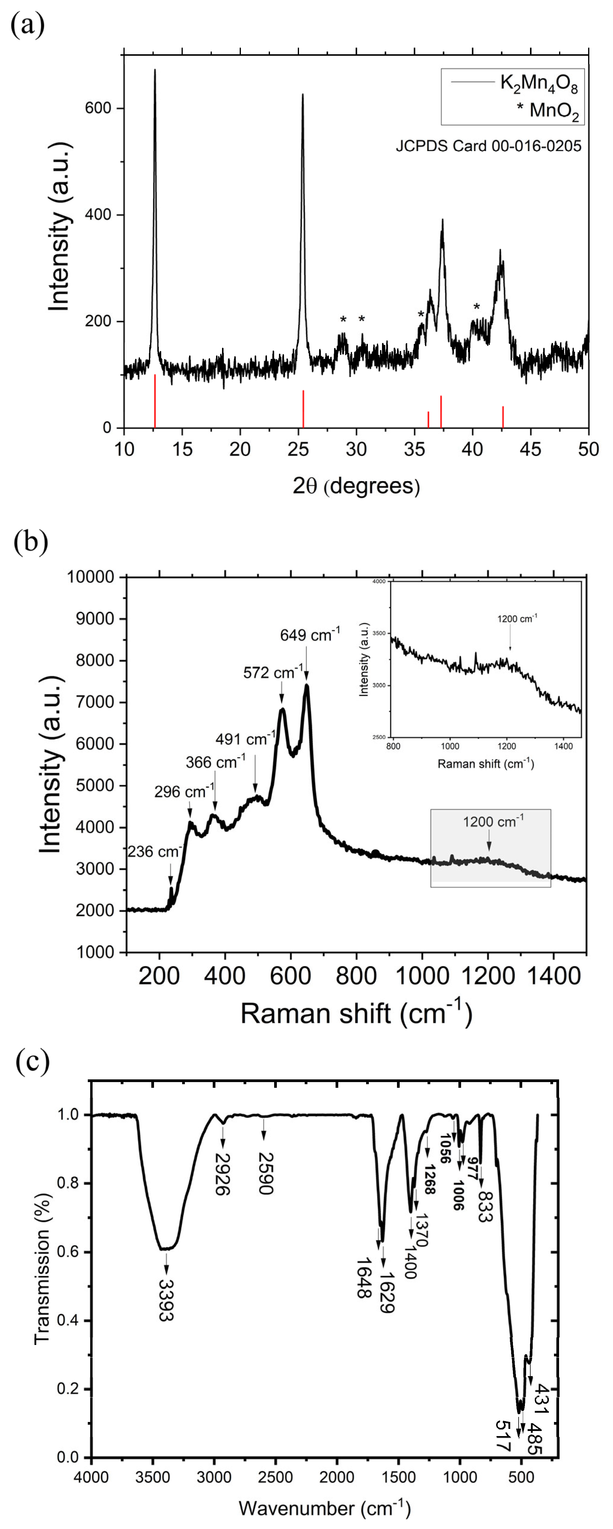
Figure 1. (a) X-ray diffraction pattern of the birnessite-type K2Mn4O8 sample (indexed according to the JCPD 00-016-0205 card); the peaks marked with * are indexed with MnO2 phases; (b) Raman spectrum at room temperature for the birnessite-type K2Mn4O8 sample; and (c) FT-IR spectrum for the birnessite-type K2Mn4O8 sample.
Solids 06 00048 g001
Figure 2. SEM image recorded of the birnessite-type K2Mn4O8 sample.
Solids 06 00048 g002
Figure 3. (a) Measured X-ray powder diffractogram for the Fe3(OHPO3)4(H2O)4 crystals (black color) indexed according to the JCPD 01-086-1656 card; (b) Raman spectrum at room temperature for the Fe3(OHPO3)4(H2O)4 sample; and (c) FT-IR spectrum for the Fe3(OHPO3)4(H2O)4 sample.
Solids 06 00048 g003aSolids 06 00048 g003b
Figure 4. SEM image recorded of the mixed-valence iron phosphate Fe3(PO3OH)4(H2O)4 sample.
Solids 06 00048 g004
Figure 5. (a) Anodic LSVs recorded on GC0, GCCB, GCM1, and GCCB-M1. (b) Cathodic LSVs recorded on GC0, GCCB, GCM1, and GCCB-M1. 0.1 M H2SO4 electrolyte solution. v = 5 mV/s.
Solids 06 00048 g005
Figure 6. (a) Capacitive current density vs. scan rate plot for the GCM1 electrode. (b) CVs recorded on a GCM1 electrode in the E range from −200 to 400 mV at increasing v values (10, 20, 30, 40, and 50 mV/s). 0.1 M KCl electrolyte solution.
Solids 06 00048 g006
Figure 7. (a) The Tafel plot obtained from the anodic LSV recorded for GCM1 in 0.1 M H2SO4 solution. (b) The Tafel plot obtained from the cathodic LSV recorded for GCM1 in 0.1 M H2SO4 solution. The current density (iECSA) is ECSA-normalized.
Solids 06 00048 g007
Figure 8. (a) Anodic polarization curves recorded on GC0, GCCB, GCM2, and GCCB-M2. (b) Cathodic polarization curves recorded on GC0, GCCB, GCM2, and GCCB-M2. 1 M KOH electrolyte solution. v = 5 mV/s.
Solids 06 00048 g008
Figure 9. (a,b) Cyclic voltammograms recorded on two GCCB-M2 electrodes in the E range between −200 and 200 mV, at increasing v values (0.01, 0.02, 0.03, 0.04, and 0.05 mV/s), in 0.1 M KCl electrolyte solution. (c) Graphical representation of the average values of the capacitive current density as a function of the scan rate.
Solids 06 00048 g009
Figure 10. (a) Tafel plot obtained from the cathodic polarization curve recorded for GCCB-M2 in 1 M KOH solution. The current density (iECSA) is ECSA-normalized. (b) Chronoamperogram obtained on GCCB-M2 in 1 M KOH solution and inset with the LSVs recorded on GCCB-M2 before (GCCB-M2′) and after (GCCB-M2″) the electrochemical experiment (1 M KOH solution, v = 5 mV/s).
Solids 06 00048 g010
Figure 11. Raman spectra obtained on the GCCB-M2 electrode before (GCCB-M2′) and after (GCCB-M2″) the chronoamperometric test.
Solids 06 00048 g011
Table 1. Labels used to identify the modified electrodes and the compositions of the catalyst inks.
Electrode
Labels
K2Mn4O8
(mg)
Fe3(PO3OH)4(H2O)4
(mg)
Carbon Black
(mg)
Nafion Solution (µL)Ethanol (µL)
GC0-----
GCCB--550450
GCM15--50450
GCCB-M15-5100900
GCM2-5-50450
GCCB-M2-55100900
Table 2. The Cdl, R2, Rf, and ECSA values determined for the GCM1 electrode.
ElectrodeCdl (mF/cm2)R2RfECSA (cm2)
GCM12.8050.999246.7513.09
Table 3. The Cdl, R2, Rf, and ECSA values determined for the GCCB-M2 electrode.
ElectrodeCdl (mF/cm2)R2RfECSA (cm2)
GCCB-M23.6370.998460.61716.973
Table 4. The values of the electrochemical parameters determined for the GCM1 and GCCB-M2 electrodes.
Electrode LabelsGCM1GCCB-M2
Parameters
ηOER (V) at i = 10 mA/cm21.070.80
ηHER (V) at i = −10 mA/cm20.9570.515
Cdl (mF/cm2)2.805
(R2 = 0.9992)
3.637
(R2 = 0.9984)
Rf46.7560.617
ECSA (cm2)13.0916.973
OER Tafel slope (V)0.180
(R2 = 0.9998)
-
HER Tafel slope (V)0.142
(R2 = 0.9993)
0.122
(R2 = 0.9998)
Disclaimer/Publisher’s Note: The statements, opinions and data contained in all publications are solely those of the individual author(s) and contributor(s) and not of MDPI and/or the editor(s). MDPI and/or the editor(s) disclaim responsibility for any injury to people or property resulting from any ideas, methods, instructions or products referred to in the content.