Article

Phase Transition Field Effect Transistor Observed in an α-(BEDT-TTF)2I3 Single Crystal

1
Department of Electrical and Electronic Engineering, Chiba University, Chiba 263-8522, Japan
2
Center for Analytical Instrumentation, Chiba University, Chiba 263-8522, Japan
*
Author to whom correspondence should be addressed.
Solids 2023, 4(3), 201-212; https://doi.org/10.3390/solids4030013
Submission received: 7 June 2023 / Revised: 6 July 2023 / Accepted: 25 July 2023 / Published: 1 August 2023

Abstract

:
The metal–insulator transition induced by the gate electric field in the charge order phase of the  α -(BEDT-TTF) 2 I 3  single-crystal field-effect transistor (FET) structure was clearly observed near the phase transition temperature. An abrupt increase in the electrical conductance induced by the applied gate electric field was evident, which corresponds to the partial dissolution of the charge order phase triggered by the gate electric field. The estimated nominal dissolved charge order region (i.e., the gate-induced metallic region) was overestimated in 130–150 K, suggesting additional effects such as Joule heating. On the other hand, in the lower temperature region below 120 K, the corresponding dissolved charge order was several monolayers of BEDT-TTF, suggesting that it is possible to dissolve the charge order phase within the bistable temperature region.

1. Introduction

Correlated electronic materials and their various phase transitions have attracted significant interest in the field of materials science. In Mott insulators, the electronic metal–insulator transition is expected to provide a new driving principle in field-effect transistors (FETs). For example, as a new type of electronic device [1,2,3,4,5,6,7,8,9,10,11,12,13,14,15,16,17,18,19,20,21,22,23], the Mott transistor driven by a metal–insulator transition, has been extensively studied. Its advantage is expected to be high-speed operation. This possibility has been investigated using 2D quantum simulations [24]. A charge order phase is also a correlated electronic state, which appears in the quarter-filling band under inter-site Coulomb interactions, and elicits a variety of phenomena such as negative differential resistance [25,26,27,28,29,30,31,32,33,34], ferroelectricity [35,36,37,38,39,40,41,42,43,44], and the thyristor effect [45]. Organic charge order materials based on bis(ethylenedithio)tetrathiafulvalene (BEDT-TTF) have been extensively studied and various characteristics related to the crystal structure, counter anion, and molecular arrangement of the unit cell have been revealed [46,47,48,49,50,51,52,53,54,55,56,57].
However, despite the extensive interest in correlated organic materials and the effect of the gate electric field on the FET structure, few studies have been conducted on this effect on organic charge order materials [7,12], mainly because of the technical difficulties in sample preparation. To observe the gate electric field effect, a single-crystal sample is required that must possess at least three conditions: (1) a mirror crystal surface, (2) an inert interface between the crystal surface and gate insulator, and (3) a sufficiently thin crystal for adherence to the gate insulator and to distinguish the enhanced electrical current produced by the gate electric field from the bulk electrical current.
In addition, excess carriers of high density are required to induce metal–insulator transitions in strongly correlated materials. Electrical double-layer gating [58,59,60,61,62,63,64] is expected to be useful for high-density carrier accumulation but is not available in the organic charge-transfer complexes because it generally dissolves the organic charge-transfer complex. Therefore, we attempted to detect the gate electric field effect near the metal–insulator transition temperature ( T MI ) instead of achieving high carrier accumulation at present. Even though a realistic applied gate voltage of up to 100 V is insufficient to inject a large number of excess carriers, a phase transition induced by an external field is expected to be observed because the energies of both the metallic and charge order phases are comparable near  T MI . In other words, with a relatively small perturbation, we expected to break the thermal equilibrium balance in the population of coexisting metallic and charge order phases. In this study, we focused on the metal–insulator phase transition of  α -(BEDT-TTF) 2 I 3 , which is a well-investigated organic charge order material comprising a donor molecule BEDT-TTF and an acceptor I 3  that undergoes a metal–insulator phase transition at approximately 140 K [53].
Moreover, we introduced technical improvements to the measurement of single-crystal organic FET. The Natural adhesion contact (NAC) used in this study was a thin-film Au four-probe electrode patterned on the surface of a thin parylene film. The NAC was so thin that it adhered spontaneously to the organic single crystals. The full details of NAC are presented in Ref. [65]. In brief, the NAC adheres to the mirror surface of any organic single crystal very softly and establishes electrical contact between the Au thin-film electrode and the crystal surface without incurring any chemical or thermal damage. Figure 1a shows a photograph of NAC peeled off from the preparation substrate. Once the parylene film is peeled off from the preparation substrate, a four-probe Au electrode pattern is fabricated on the parylene thin film surface. The resulting NAC can be laminated onto the surface of an organic single crystal.

2. Experimental Details

Single crystals of  α -(BEDT-TTF) 2 I 3  were grown via electrocrystallization. BEDT-TTF powder (3.6 mg) and tetrabutylammonium iodide (35.5 mg) were dissolved in benzonitrile (8 mL of benzonitrile at the anode and cathode sides, respectively). Two Pt wires were used as the electrodes for electrocrystallization. These procedures were conducted entirely in a glove box of N 2 . During the growth, the cell was maintained at a temperature of 308 K, and a constant electrical current of 0.3∼0.4  μ A was applied. The grown crystals were handled in anhydrous ethanol and settled on the surface of a polydimethylsiloxane (PDMS)-coated Neoplim film (Mitsubishi Gas Chemical Company Inc., Tokyo, Japan). The thermal expansion coefficient of the Neoplim film was 58 ppm/K. The thicknesses of the PDMS layer and Neoplim film were 800 nm and 50  μ m, respectively. Therefore, the strain or slippage at the interface of the organic single crystal and substrate was effectively suppressed using PDMS/Neoplim. A single crystal of  α -(BEDT-TTF) 2 I 3  on a substrate surface was selected and electrically contacted using the NAC. Figure 1b shows an optical micrograph of the thin  α -(BEDT-TTF) 2 I 3  single crystal and the NAC placed on the crystal. A cross-sectional view of the FET measurement sample is shown in Figure 1c. The gate electrode in the NAC for FET measurement existed on the back side of the contact electrode plane in the 900 nm thick parylene thin film.
The terminal gap of the NAC between V 1  and V 2  was 40  μ m, and the source–drain distance (channel length) and width were 180 and 50  μ m, respectively. The NAC was placed on a single crystal using a four-axis xyz θ  microstage. Four-terminal electrical measurements were conducted under an applied drain voltage of −0.2 V (from room temperature to 160 K), the lowest voltage possible, then slightly raised to −0.5 V (160 K to 110 K) to maintain a sufficiently S/N ratio in the high electrical resistivity regime below  T MI . Electrical current measurements and the application of drain voltage were performed using a DC voltage/current generator (Model R6245, Advantest Corp., Tokyo, Japan). The four-terminal potential difference was measured using a digital multimeter (3458A; Keysight Technologies, California, CA, USA). The gate voltage was generated by a system source meter (Keithley 2635A).
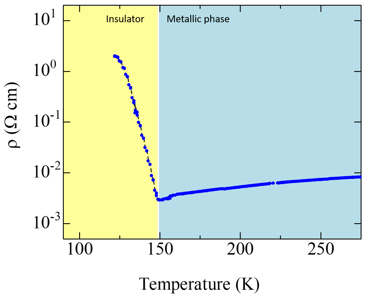
Figure 2 shows a typical example of the temperature dependence of the electrical resistivity of a  α -(BEDT-TTF) 2 I 3  single crystal measured using NAC. The metal–insulator phase transition was clearly observed, and almost no temperature hysteresis was observed in the cooling and heating cycles, demonstrating the reliability of the NAC contact even at low temperatures. The observed increase in the electrical resistance during the metal–insulator transition is sample dependent. The difference in the four-terminal electrical resistance arises mainly from the difference in the crystal uniformity. If the active phase transition path has a parallel nonactive conductor path, the observed temperature-dependent variation during the metal–insulator transition appears relatively weak. In addition, a slight shift in  T MI  was sometimes observed and was also dependent on the sample. It has been discussed that the phase transition temperature is increased in part by the induced stress in the organic crystal, which is probably the result of a difference in the thermal expansion coefficient between the organic crystal and the Neoplim substrate. In the present setup, the thermal expansion of the sample is dominated by the thermal expansion of Neoplim because its volume is predominantly greater than that of either the organic single crystal or the PDMS layer. The presence of the PDMS layer suppressed this effect; however, the difference in the thermal expansion induced tensile strain in the organic single crystal.

3. Results and Discussion

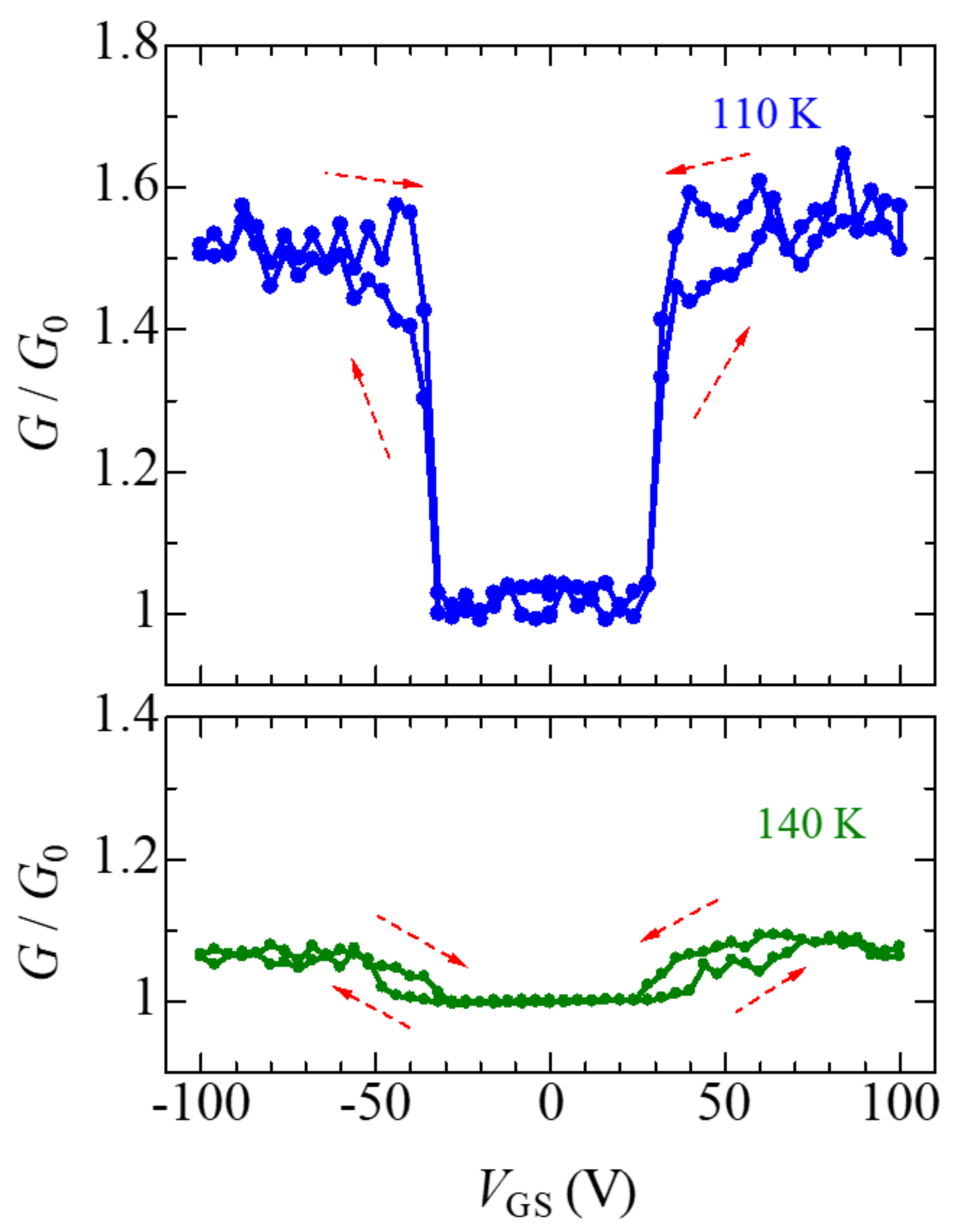
Figure 3 shows the temperature dependence of relative electrical conductance ( G / G 0 ) with respect to the applied  V GS . The electrical conductance (G) was normalized by the bulk electrical conductance under zero-gate voltage ( G 0 ) at each temperature. Therefore, the  V GS -induced increase in  G / G 0  appeared to be relatively large at lower temperatures. At 140 K,  G / G 0  was almost constant as  V GS  increased from 0 to 32 V, then gradually increased as  V GS  increased from 40 V, and saturated at about 1.07–1.08 as  V GS  increased to 100 V. When  V GS  decreases,  G / G 0  remains at its saturated value of ∼1.08 down to 36 V, then decreases abruptly to approximately 1.0 as  V GS  decreases from 36 V to 24 V. In addition, for negative  V GS G / G 0  began to increase below −50 V, and then saturated from −52 V to −100 V. Along the decreasing  V GS  path, the saturated  G / G 0  value remained until  V GS  reached −44 V, and then decreased abruptly to approximately 1.0 below −28 V. Hysteresis was observed in the four-probe transfer curve. At 110 K,  G / G 0  began to rise sharply at  V GS  = 28 V in the upsweep path and abruptly decreased at  V GS  = 36 V. The contribution of the hysteresis in the four-probe transfer curve observed at 110 K was relatively lower than that at 140 K. These FET characteristics were observed in four-probe measurements; however, the gate-induced modulation of electrical conductance was hardly observed in the two-probe measurements because of the large contact resistance.
The sharp increase in conductance is considered to arise from the partial melting of the correlated charge order electronic phase. Either the excess carriers injected during the  V GS  application could suppress the correlation effect or the excess carrier flow current could break the charge order domain. Consequently, the metallic phase fragments distributed in the channel connect to form a continuous metallic path. Therefore,  G / G 0  indicates a steep increase in threshold voltage. This principle is completely different from that of conventional semiconductor field-effect transistors. In addition, the  V GS -induced metal–insulator transition was observed under both positive and negative polarizations of  V GS  because of the low energy gap which was estimated from the observed thermal activation-type temperature dependence of the electrical resistance below  T c  (approximately 0.11 eV). That is, the charge gap of the charge order phase caused by Coulomb repulsion is small; therefore, electrons and holes are injected by applying a positive and negative gate electric field, respectively.
The amount of the gate-induced metallic phase was estimated using the framework described below. The effects of the induced carrier in the FET structure are only effective in several molecular layers at the interface of the gate insulator and crystal. Hence, the field-induced metallic phase was limited to the channel region of the FET. However, in this phase-transition FET, the electric-field-induced carriers not only create a channel by themselves but also possibly induce a metallic region in their periphery because the charge order is strongly correlated, and the collective electronic state (i.e., melting of the charge order fragment) may also induce the collapse of the surrounding charge order domain. We later estimated the induced collapse of charge order.
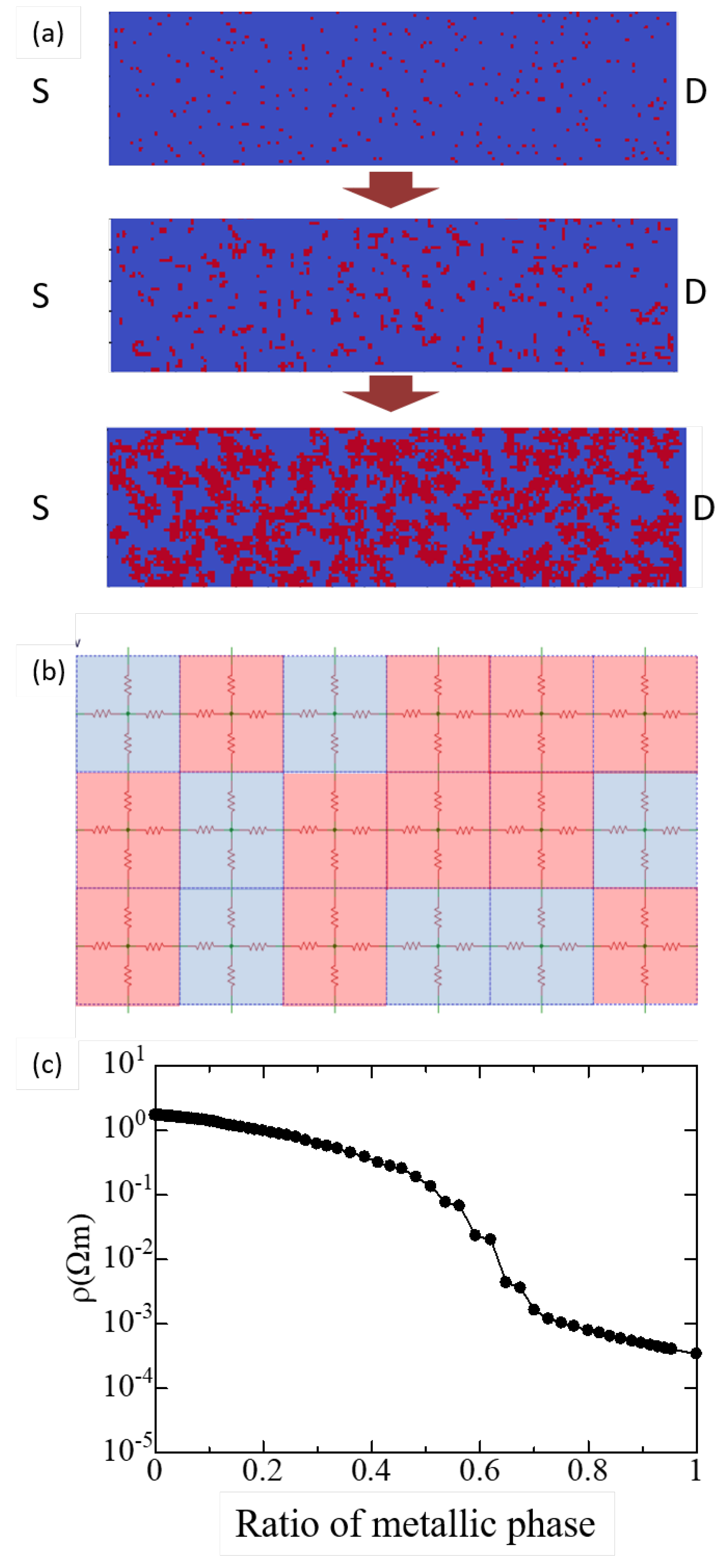
We employed a simple phase transition model that has been widely applied to many phenomena. As shown in Figure 4a, starting from the whole metallic bulk crystal, randomly distributed seeds of insulator began to grow. Subsequently, the volume of the insulator phase gradually increased in the metallic bulk, and the combined resistance between the source and drain abruptly increased because of the fragmentation of the continuous metallic path. Figure 4b shows a magnified view of the 180 × 90 cell square network of the electrical resistance of the metallic and insulating domains. This material is well known as a two-dimensional conductor [54,55]; therefore, the electrical conduction in this material is discussed in two-dimentional in-plane conduction models based on the fact that the interlayer transfer integrals are sufficiently small compared to in-plane transfer integrals [56,57]. The seed of the insulator phase was randomly distributed in the entire metallic bulk crystal in the initial state, and the insulator seed grew by replacing the metallic site with the insulator site in the neighboring site of the insulator domain. The combined electrical resistivity of the resistance network was calculated at every step of the insulator domain growth. The combined resistance of the resistance network was calculated using the generated 100 ways of metallic and insulating phase distributions. Each result converged, and the average electrical resistivity was calculated. Figure 4c presents the calculated combined electrical resistivity for the metallic phase ratio. The calculated resistivity varied from 10 0  to 10 4   Ω m. The calculated resistivity decreased steeply at a metallic ratio of approximately 0.55. This indicates that a 0.55 metallic ratio is necessary for the formation of a continuous metallic path from the source to the drain.
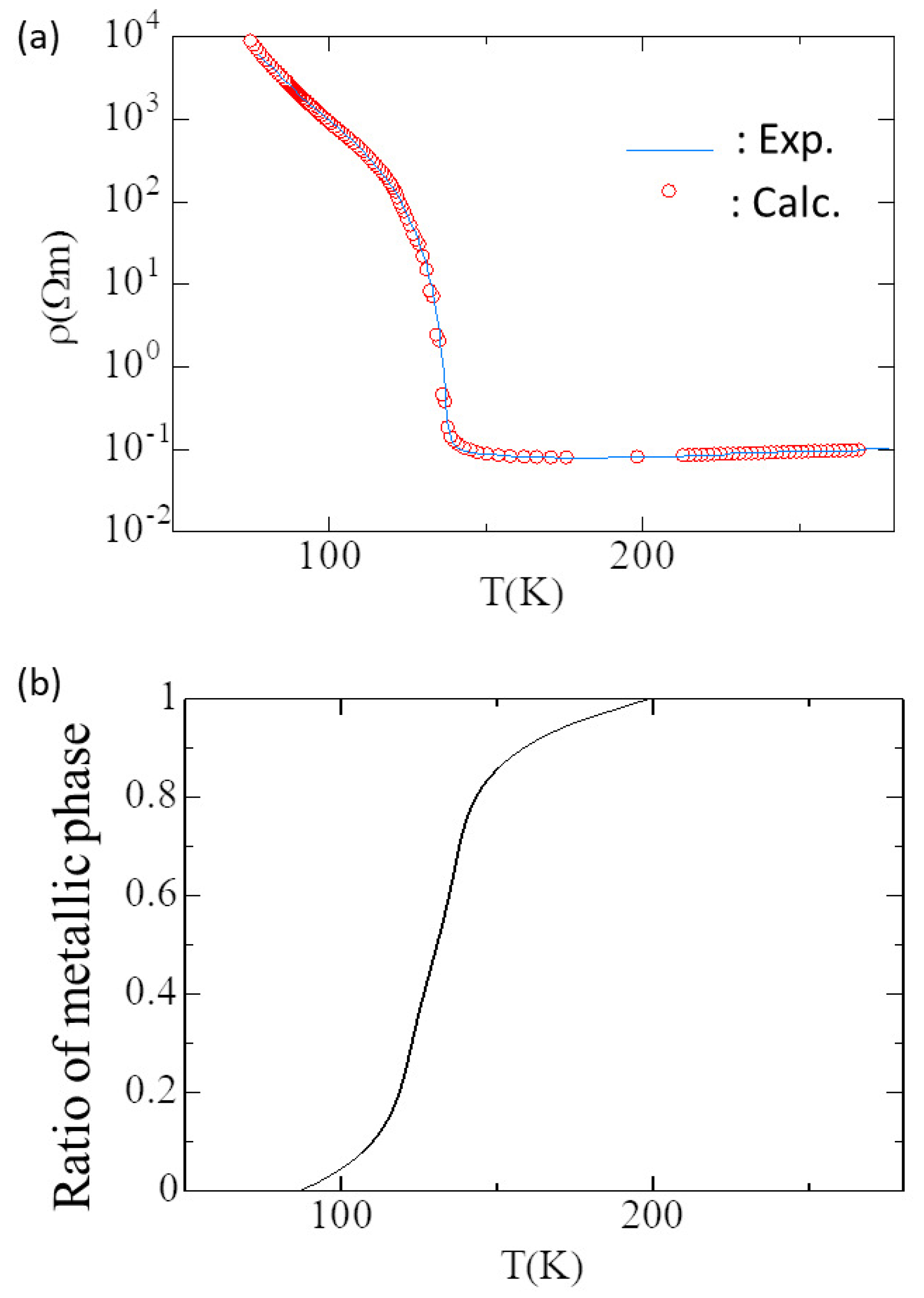
The solid blue line in Figure 5a shows the temperature dependence of the electrical resistivity of  α –(BEDT-TTF) 2 I 3  [52]. The red circles are the calculated electrical resistivities based on the phase transition model, including the thermal carrier generation in the insulator phase. The thermal activation energy of the electrical resistivity of the insulator phase considered in this curve fitting is 0.1103 eV. The temperature dependence of the resistivity of the metallic phase is also included as  T . The calculated plot corresponded well with the experimental data. In the process of curve fitting between the experimental data and the calculations, we assumed a temperature dependence of the metallic phase ratio, as shown in Figure 5b. Consequently, we extracted the metallic phase ratio as a function of the temperature, as shown in Figure 5b. The metallic phase ratio was almost zero below 90 K, increased with temperature, and approached 1.0 toward 200 K. Although the steepest slope of resistivity was observed at around 140 K, the ratio of the metallic phase continuously changed from 90 K to 200 K. Thus, we clearly indicate that the temperature dependence of the electrical resistivity of  α -(BEDT-TTF) 2 I 3  can be explained by the temperature dependence of the metallic phase ratio and thermal carrier generation across an energy gap of 0.1103 eV. The observed thermal activation energy can be attributed to the charge gap of the charge order phase.
The temperature region where the transfer characteristics of the FET were observed was 100–150 K, which corresponds to the temperature region where the metallic and insulator phases coexisted. Therefore, we conclude that coexistence is essential for inducing a shift in the metallic phase ratio using an external gate electric field. Therefore, we next estimated the extent to which the metallic phase ratio increase corresponds to the observed gate-induced increase in electrical conductance based on the phenomenological metal–insulator coexistence situation. Because the physical principle of the observed gate-induced increase in electrical conductance is not clearly revealed, we attempted to explain the observed characteristics by a simple phenomenological model as described below.
The number of the total molecular layer in the crystal was roughly estimated to be
n = total thickness d ( 001 ) = 1.0 μ m 1.710 nm = 585 ,
using lattice parameter values a = 9.21 Å, b = 10.85 Å, c = 17.49 Å,  α  = 96.95°,  β  = 97.97°, and  γ  = 90.75° for this analysis. Here, d(001) is the interplanar distance of the equivalent (001) plane, calculated from the lattice parameters.
Next, we developed a simple model in which the observed electrical conductance  G total  consists of the parallel-combined conductance of the gate-induced metallic layer (GIML) and the bulk layer (corresponding to zero  V GS ). Therefore,
G total = G GIML + G zero V GS
= σ GIML · L W · t GIML + σ zero V GS · L W · t zero V GS
= σ GIML t GIML + σ zero V GS t zero V GS · L W
= σ GIML x + σ zero V GS ( n x ) · L d ( 001 ) · W ,
where x denotes the number of gate-induced metallic layers;  σ GIML  and  σ zero V GS  denote the electrical conductivity of the GIML and the zero  V GS  layer, respectively. Here, we assumed  σ GIML  to be approximately equal to the electrical conductivity of the fully metallic phase, which approximately corresponds to that at 160 K (approximately 6 × 10 1 Ω cm). In this formula,  G total  at each temperature is expressed as a function of x. In contrast,  G 0  corresponds to the  G zero V GS  under x = 0 (i.e., bulk conductance at the temperature), and therefore,
G 0 = σ zero V GS n · L d ( 001 ) · W .
Hence, we obtained
G total G 0 = σ GIML x + σ zero V GS ( n x ) / σ zero V GS n .
Thus, we can estimate the number of corresponding GIMLs from the gate variation in the relative conductance.
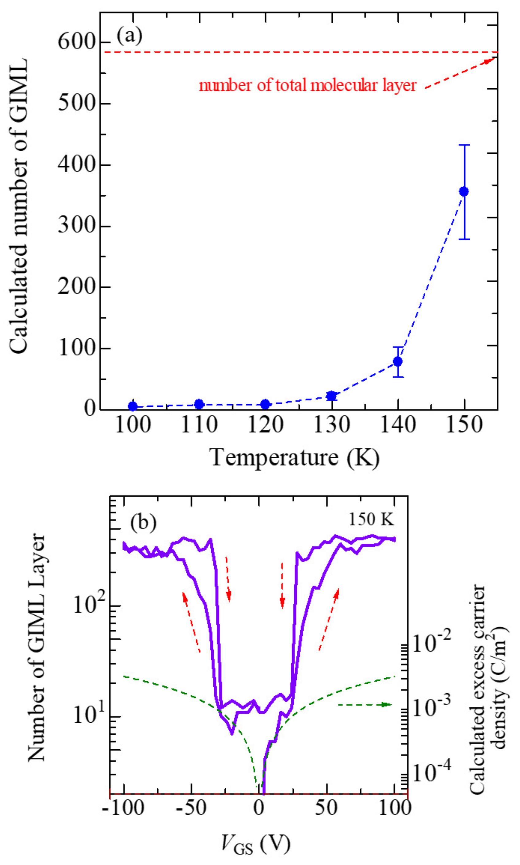
Figure 6a shows the temperature dependence of the calculated number of GIMLs. The nominal GIMLs were approximately 290–440 layers at 150 K; however, this value is so large that it cannot be explained by the gate field effect alone because the effect of the gate electric field is limited by the Debye length. The realistic number of GIML should be several MLs. The overestimation suggests the existence of an additional effect. The local Joule heat generated by the electrical current is a possible additional effect. The nominal number of GIMLs decreased with decreasing temperature, until it fell below five layers at 100 K. A GIML is relatively easy to generate at 150 K because the free energy of the metallic phase is not significantly different from that of the charge order phase. Therefore, a small perturbation produced by the external  V GS  and an additional effect could be sufficient to collapse the charge order phase. On the other hand, at 100 K, the charge order phase dominated the bulk, implying that the thermal stability of the charge order phase was stronger than that of the metallic phase. Therefore, making a charge order phase undergo a  V GS -induced metal-insulator phase transition is relatively difficult at lower temperatures. In addition, the additional Joule heating effect is hard to continue in this temperature region because the ratio of metallic phase is below 10 percent; therefore, a continuous conductive filament path hardly exists. The Joule heating effect is suppressed in this temperature region.
An example of variation in the nominal number of GIMLs with  V GS  at 150 K (Figure 6b) shows the  V GS  hysteresis (red arrows in the figure) being quite consistent with the GIML behavior in the temperature range where the charge order and metallic phases coexist. From zero- V GS  to 100 V or −100 V, that is, the upsweep path, it starts with the GIML being less than one monolayer and gradually increases owing to the effect of the gate electric field. In contrast, starting from 100 V or −100 V (i.e., the down-sweep path), with GIML already present, the GIML stability was higher than that in the up-sweep path. This mechanism underlies the observed  V GS -hysteresis. The calculated nominal excess carrier density induced by the gate electric field (the dashed green curve in Figure 6b) corresponds well with the sub-threshold region of the observed four-probe transfer curve. Therefore, field-effect excess carrier injection occurs even in the subthreshold region. In this region, the device works as a normal organic FET. However, the number of GIMLs abruptly begins to increase and saturates when the excess charge density exceeds the tipping point. For positive  V GS , the number of GIMLs begins to increase at 7.8 × 10 4 C/m 2  (at  V GS  = 24 V) and saturates at 1.82 × 10 3 C/m 2  (at 56 V). For a negative  V GS , the number begins to increase at 1.0 × 10 3  C/m 2  (at −32 V) and saturates at 2.1 × 10 3  C/m 2  (at −64 V). 7.8 × 10 4  C/m 2  corresponding to 1.2 × 10 3  electrons per BEDT-TTF molecule. It is said that this number of excess carriers is generally insufficient to force the charge order phase to melt. However, in the temperature region where metallic and charge order phases coexist, a small perturbation, such as local excess charge and the succeeding Joule heating, could trigger the partial and transient metallic domain generation. We demonstrated that some of the charge order domains possibly change to the metallic domain from a relatively small number of excess carriers in the coexistence temperature region.

4. Conclusions

The metal–insulator transition induced by the gate electric field for the  α -(BEDT-TTF) 2 I 3  single-crystal FET was observed near the charge order phase transition temperature. The technical progress of NAC enabled us to observe partial gate-induced charge order melting. We estimated the temperature dependence of the metallic phase ratio in bulk by combining the percolation-based phase transition model and the electrical resistance network. In addition, we attempted to explain the observed FET characteristics by a simple phenomenological model. The estimated corresponding dissolved charge order region was overestimated; however, this overestimation suggests the existence of additional effects, such as simultaneous Joule heating. At present, the physical principle of this FET operation has not been revealed, and we are trying to reveal it by using extended Hubbard model calculation.

Author Contributions

Formal analysis and investigation, R.A., R.W. and H.M.; resources, R.A.; writing—original draft preparation, M.S. and R.A.; writing—review and editing, M.S. and R.W.; supervision, M.S.; funding acquisition, K.K. and M.S. All authors have read and agreed to the published version of the manuscript.

Funding

This work was financially supported by a Grant-in-Aid for Scientific Research (#17H02760) from the Ministry of Education, Culture, Sports, Science and Technology, Japan.

Data Availability Statement

The data presented in this study are available on request from the corresponding author.

Acknowledgments

The authors thank Takahiro Ueda, Hiroki Watanabe, Masahiko Kishi and Yugo Okada for their experimental help, and Riku Takeda for help with the analysis.

Conflicts of Interest

The authors declare no conflict of interest. The funders had no role in the design of the study; in the collection, analyses, or interpretation of data; in the writing of the manuscript, or in the decision to publish the results.

References

  1. Zhou, C.; Newns, D.M.; Misewich, J.A.; Pattnaik, P.C. A field effect transistor based on the Mott transition in a molecular layer. Appl. Phys. Lett. 1997, 70, 598–600. [Google Scholar] [CrossRef] [Green Version]
  2. Newns, D.M.; Misewich, J.A.; Tsuei, C.C.; Gupta, A.; Scott, B.A.; Schrott, A. Mott transition field effect transistor. Appl. Phys. Lett. 1998, 73, 780–782. [Google Scholar] [CrossRef]
  3. Hormoz, S.; Ramanathan, S. Limits on vanadium oxide Mott metal–insulator transition field-effect transistors. Solid-State Electron. 2010, 54, 654–659. [Google Scholar] [CrossRef]
  4. Zhou, Y.; Ramanathan, S. Correlated electron materials and field effect transistors for logic: A review. Crit. Rev. Solid State Mater. Sci. 2013, 38, 286–317. [Google Scholar] [CrossRef] [Green Version]
  5. Hasegawa, T.; Mattenberger, K.; Takeya, J.; Batlogg, B. Ambipolar field-effect carrier injections in organic Mott insulators. Phys. Rev. B 2004, 69, 245115. [Google Scholar] [CrossRef]
  6. Sakai, M.; Sakuma, H.; Ito, Y.; Saito, A.; Nakamura, M.; Kudo, K. Ambipolar field-effect transistor characteristics of (BEDT-TTF)(TCNQ) crystals and metal-like conduction induced by a gate electric field. Phys. Rev. B 2007, 76, 045111. [Google Scholar] [CrossRef]
  7. Yamamoto, H.M.; Hosoda, M.; Kawasugi, Y.; Tsukagoshi, K.; Kato, R. Field effect on organic charge-ordered/Mott insulators. Phys. B Condens. Matter 2009, 404, 413–415. [Google Scholar] [CrossRef]
  8. Sakai, M.; Ito, Y.; Takahara, T.; Ishiguro, M.; Nakamura, M.; Kudo, K. Ferroelectriclike dielectric response and metal-insulator transition in organic Mott insulator-gate insulator interface. J. Appl. Phys. 2010, 107, 043711. [Google Scholar] [CrossRef]
  9. Kawasugi, Y.; Yamamoto, H.M.; Hosoda, M.; Tajima, N.; Fukunaga, T.; Tsukagoshi, K.; Kato, R. Strain-induced superconductor/insulator transition and field effect in a thin single crystal of molecular conductor. Appl. Phys. Lett. 2008, 92, 243508. [Google Scholar] [CrossRef]
  10. Kawasugi, Y.; Yamamoto, H.M.; Tajima, N.; Fukunaga, T.; Tsukagoshi, K.; Kato, R. Field-Induced Carrier Delocalization in the Strain-Induced Mott Insulating State of an Organic Superconductor. Phys. Rev. Lett. 2009, 103, 116801. [Google Scholar] [CrossRef] [Green Version]
  11. Kawasugi, Y.; Yamamoto, H.M.; Tajima, N.; Fukunaga, T.; Tsukagoshi, K.; Kato, R. Electric-field-induced Mott transition in an organic molecular crystal. Phys. Rev. B 2011, 84, 125129. [Google Scholar] [CrossRef]
  12. Kimata, M.; Ishihara, T.; Ueda, A.; Mori, H.; Tajima, H. Fabrication of a field effect transistor structure using charge-ordered organic materials α-(BEDT-TTF)2I3 and α’-(BEDT-TTF)2IBr2. Synth. Met. 2013, 173, 43–45. [Google Scholar] [CrossRef]
  13. Kimata, M.; Ishihara, T.; Tajima, H. Electrostatic Charge Carrier Injection into the Charge-Ordered Organic Material α-(BEDT-TTF)2I3. J. Phys. Soc. Jpn. 2012, 81, 073704. [Google Scholar] [CrossRef]
  14. Hasegawa, H.; Noguchi, Y.; Ueda, R.; Kubota, T.; Mashiko, S. Organic Mott insulator-based nanowire formed by using the Nanoscale-electrocrystallization. Thin Solid Film. 2008, 516, 2491–2494. [Google Scholar] [CrossRef]
  15. Yamamoto, H.M.; Ueno, J.; Kato, R. Critical behavior of a filling-controlled Mott-transition observed at an organic field-effect-transistor interface. Eur. Phys. J. Spec. Top. 2013, 222, 1057–1063. [Google Scholar] [CrossRef]
  16. Yamamoto, H.M.; Suda, M.; Kawasugi, Y. Organic phase-transition transistor with strongly correlated electrons. Jpn. J. Appl. Phys. 2018, 57, 03EA02. [Google Scholar] [CrossRef]
  17. Suda, M.; Takashina, N.; Namuangruk, S.; Kungwan, N.; Sakurai, H.; Yamamoto, H.M. N-Type Superconductivity in an Organic Mott Insulator Induced by Light-Driven Electron-Doping. Adv. Mater. 2017, 29, 1606833. [Google Scholar] [CrossRef]
  18. Yang, F.; Suda, M.; Yamamoto, H.M. Fabrication and Operation of Monolayer Mott FET at Room Temperature. Bull. Chem. Soc. Jpn. 2017, 90, 1259–1266. [Google Scholar] [CrossRef] [Green Version]
  19. Kawasugi, Y.; Seki, K.; Edagawa, Y.; Sato, Y.; Pu, J.; Takenobu, T.; Yunoki, S.; Yamamoto, H.; Kato, R. Electron-hole doping asymmetry of Fermi surface reconstructed in a simple Mott insulator. Nat. Commun. 2016, 7, 12356. [Google Scholar] [CrossRef] [PubMed] [Green Version]
  20. Kawasugi, Y.; Seki, K.; Edagawa, Y.; Sato, Y.; Pu, J.; Takenobu, T.; Yunoki, S.; Yamamoto, H.M.; Kato, R. Simultaneous enhancement of conductivity and Seebeck coefficient in an organic Mott transistor. Appl. Phys. Lett. 2016, 109, 233301. [Google Scholar] [CrossRef] [Green Version]
  21. Suda, M.; Kawasugi, Y.; Minari, T.; Tsukagoshi, K.; Kato, R.; Yamamoto, H.M. Strain-Tunable Superconducting Field-Effect Transistor with an Organic Strongly-Correlated Electron System. Adv. Mater. 2014, 26, 3490–3495. [Google Scholar] [CrossRef]
  22. Yamamoto, H.M.; Kawasugi, Y.; Cui, H.; Nakano, M.; Iwasa, Y.; Kato, R. Asymmetric Phase Transitions Observed at the Interface of a Field-Effect Transistor Based on an Organic Mott Insulator. Eur. J. Inorg. Chem. 2014, 2014, 3841–3844. [Google Scholar] [CrossRef]
  23. Suda, M.; Yamamoto, H.M. Field-, strain- and light-induced superconductivity in organic strongly correlated electron systems. Phys. Chem. Chem. Phys. 2018, 20, 1321–1331. [Google Scholar] [CrossRef]
  24. Newns, D.; Doderer, T.; Tsuei, C.; Donath, W.; Misewich, J.; Gupta, A.; Grossman, B.; Schrott, A.; Scott, B.; Pattnaik, P.; et al. The Mott transition field effect transistor: A nanodevice? J. Electroceram. 2000, 4, 339–344. [Google Scholar] [CrossRef]
  25. Mori, T.; Terasaki, I.; Mori, H. New aspects of nonlinear conductivity in organic charge-transfer salts. J. Mater. Chem. 2007, 17, 4343–4347. [Google Scholar] [CrossRef]
  26. Ivek, T.; Kovačević, I.; Pinterić, M.; Korin-Hamzić, B.; Tomić, S.; Knoblauch, T.; Schweitzer, D.; Dressel, M. Cooperative dynamics in charge-ordered state of α-(BEDT-TTF) 2 I 3. Phys. Rev. B 2012, 86, 245125. [Google Scholar] [CrossRef] [Green Version]
  27. Itose, F.; Kawamoto, T.; Mori, T. Collective response to alternating current in the organic conductor α-(bis (ethylenedithio) tetrathiafulvalene) 2I3. J. Appl. Phys. 2013, 113, 213702. [Google Scholar] [CrossRef]
  28. Itose, F.; Kawamoto, T.; Mori, T. Rapid voltage oscillations and ac-dc interference phenomena in the two-dimensional charge-ordered organic conductor β”-(bis (ethylenedithio) tetrathiafulvalene) 3 (ClO4) 2. J. Appl. Phys. 2012, 112, 033714. [Google Scholar] [CrossRef]
  29. Tamura, K.; Ozawa, T.; Bando, Y.; Kawamoto, T.; Mori, T. Voltage oscillation associated with nonlinear conductivity in the organic conductor α-(BEDT-TTF) 2I3. J. Appl. Phys. 2010, 107, 103716. [Google Scholar] [CrossRef]
  30. Ito, A.; Nakamura, Y.; Nakamura, A.; Kishida, H. Measurement of the Nonlinear Conducting States of α-(BEDT- TTF) 2 I 3 Using Electronic Raman Scattering. Phys. Rev. Lett. 2013, 111, 197801. [Google Scholar] [CrossRef]
  31. Sabeth, F.; Iimori, T.; Ohta, N. Insulator–metal transitions induced by electric field and photoirradiation in organic mott insulator deuterated κ-(BEDT-TTF) 2Cu [N (CN) 2] Br. J. Am. Chem. Soc. 2012, 134, 6984–6986. [Google Scholar] [CrossRef]
  32. Inagaki, K.; Terasaki, I.; Mori, H.; Mori, T. Large dielectric constant and giant nonlinear conduction in the organic conductor θ-(BEDT-TTF) 2CsZn (SCN) 4. J. Phys. Soc. Jpn. 2004, 73, 3364–3369. [Google Scholar] [CrossRef] [Green Version]
  33. Mori, T.; Bando, Y.; Kawamoto, T.; Terasaki, I.; Takimiya, K.; Otsubo, T. Giant nonlinear conductivity and spontaneous current oscillation in an incommensurate organic superconductor. Phys. Rev. Lett. 2008, 100, 037001. [Google Scholar] [CrossRef] [PubMed]
  34. Mori, T.; Ozawa, T.; Bando, Y.; Kawamoto, T.; Niizeki, S.; Mori, H.; Terasaki, I. Nonlinear dynamics of conduction electrons in organic conductors. Phys. Rev. B 2009, 79, 115108. [Google Scholar] [CrossRef] [Green Version]
  35. Itoh, H.; Itoh, K.; Goto, K.; Yamamoto, K.; Yakushi, K.; Iwai, S. Efficient terahertz-wave generation and its ultrafast optical modulation in charge ordered organic ferroelectrics. Appl. Phys. Lett. 2014, 104, 173302. [Google Scholar] [CrossRef]
  36. Yamamoto, K.; Kowalska, A.A.; Yue, Y.; Yakushi, K. E–mv coupling of vibrational overtone in organic conductors: Relationship to optical nonlinearities and ferroelectricity. Phys. B Condens. Matter 2012, 407, 1775–1778. [Google Scholar] [CrossRef]
  37. Yamamoto, K.; Kowalska, A.A.; Yakushi, K. Second-harmonic generation microscopy of ferroelectric organic conductor using hydrostatic pressure apparatus with Ar as a heat sink. Phys. Status Solidi C 2012, 9, 1189–1192. [Google Scholar] [CrossRef]
  38. Yamamoto, K.; Kowalska, A.A.; Yakushi, K. Direct observation of ferroelectric domains created by Wigner crystallization of electrons in α-[bis (ethylenedithio) tetrathiafulvalene] 2I3. Appl. Phys. Lett. 2010, 96, 122901. [Google Scholar] [CrossRef]
  39. Monceau, P. Electronic crystals: An experimental overview. Adv. Phys. 2012, 61, 325–581. [Google Scholar] [CrossRef] [Green Version]
  40. Yamamoto, K.; Iwai, S.; Boyko, S.; Kashiwazaki, A.; Hiramatsu, F.; Okabe, C.; Nishi, N.; Yakushi, K. Strong optical nonlinearity and its ultrafast response associated with electron ferroelectricity in an organic conductor. J. Phys. Soc. Jpn. 2008, 77, 074709. [Google Scholar] [CrossRef] [Green Version]
  41. Yamamoto, K.; Kowalska, A.; Nakano, C.; Yakushi, K. Inhomogeneous ferroelectric polarization in α’-(BEDT-TTF) 2IBr2 revealed by second-harmonic generation microscopy. Phys. B Condens. Matter 2010, 405, S363–S364. [Google Scholar] [CrossRef]
  42. Nakaya, H.; Itoh, K.; Takahashi, Y.; Itoh, H.; Iwai, S.; Saito, S.; Yamamoto, K.; Yakushi, K. Terahertz responses of the high-temperature metallic phase and photoinduced metallic state in the ferroelectric charge-ordered organic salt α-(ET) 2 I 3. Phys. Rev. B 2010, 81, 155111. [Google Scholar] [CrossRef]
  43. Nad, F.; Monceau, P. Dielectric response of the charge ordered state in quasi-one-dimensional organic conductors. J. Phys. Soc. Jpn. 2006, 75, 051005. [Google Scholar] [CrossRef]
  44. Ishihara, S. Electronic ferroelectricity and frustration. J. Phys. Soc. Jpn. 2010, 79, 011010. [Google Scholar] [CrossRef] [Green Version]
  45. Sawano, F.; Terasaki, I.; Mori, H.; Mori, T.; Watanabe, M.; Ikeda, N.; Nogami, Y.; Noda, Y. An organic thyristor. Nature 2005, 437, 522–524. [Google Scholar] [CrossRef] [PubMed]
  46. Kawakami, Y.; Fukatsu, T.; Sakurai, Y.; Unno, H.; Itoh, H.; Iwai, S.; Sasaki, T.; Yamamoto, K.; Yakushi, K.; Yonemitsu, K. Early-stage dynamics of light-matter interaction leading to the insulator-to-metal transition in a charge ordered organic crystal. Phys. Rev. Lett. 2010, 105, 246402. [Google Scholar] [CrossRef]
  47. Seo, H. Broken symmetry states in quasi-one-dimensional molecular conductors–competitions, co-existences, and frustration–. Phys. B Condens. Matter 2010, 405, S126–S130. [Google Scholar] [CrossRef]
  48. Wojciechowski, R.; Yamamoto, K.; Yakushi, K.; Inokuchi, M.; Kawamoto, A. High-pressure Raman study of the charge ordering in α-(B E D T- T T F) 2 I 3. Phys. Rev. B 2003, 67, 224105. [Google Scholar] [CrossRef]
  49. Yue, Y.; Yamamoto, K.; Uruichi, M.; Nakano, C.; Yakushi, K.; Yamada, S.; Hiejima, T.; Kawamoto, A. Nonuniform site-charge distribution and fluctuations of charge order in the metallic state of α-(BEDT-TTF) 2 I 3. Phys. Rev. B 2010, 82, 075134. [Google Scholar] [CrossRef] [Green Version]
  50. Ivek, T.; Korin-Hamzic, B.; Milat, O.; Tomic, S.; Clauss, C.; Drichko, N.; Schweitzer, D.; Dressel, M. Electrodynamic response of the charge ordering phase: Dielectric and optical studies of α-(BEDT-TTF) 2I3. Phys. Rev. B 2011, 83, 10–1103. [Google Scholar] [CrossRef] [Green Version]
  51. Kodama, K.; Kimata, M.; Takahide, Y.; Kurita, N.; Harada, A.; Satsukawa, H.; Terashima, T.; Uji, S.; Yamamoto, K.; Yakushi, K. Charge Transport in Charge-Ordered States of Two-Dimensional Organic Conductors, α-(BEDT-TTF) 2I3 and α’-(BEDT-TTF) 2IBr2. J. Phys. Soc. Jpn. 2012, 81, 044703. [Google Scholar]
  52. Tajima, N.; Fujisawa, J.I.; Naka, N.; Ishihara, T.; Kato, R.; Nishio, Y.; Kajita, K. Photo-induced Insulator–Metal Transition in an Organic Conductor α-(BEDT-TTF) 2I3. J. Phys. Soc. Jpn. 2005, 74, 511–514. [Google Scholar]
  53. Tajima, N.; Sugawara, S.; Tamura, M.; Nishio, Y.; Kajita, K. Electronic phases in an organic conductor α-(BEDT-TTF) 2I3: Ultra narrow gap semiconductor, superconductor, metal, and charge-ordered insulator. J. Phys. Soc. Jpn. 2006, 75, 051010. [Google Scholar] [CrossRef] [Green Version]
  54. Mori, T.; Kobayashi, A.; Sasaki, Y.; Kobayashi, H.; Saito, G.; Inokuchi, H. Band structures of two types of (BEDT-TTF) 2I3. Chem. Lett. 1984, 13, 957–960. [Google Scholar]
  55. Bender, K.; Dietz, K.; Endres, H.; Helberg, H.W.; Hennig, I.; Keller, H.J.; Schäfer, H.; Schweitzer, D. (BEDT-TTF)+ 2J-3: A Two-Dimensional Organic Metal. Mol. Cryst. Liq. Cryst. 1984, 107, 45–53. [Google Scholar] [CrossRef] [Green Version]
  56. Ohki, D.; Yoshimi, K.; Kobayashi, A.; Misawa, T. Gap opening mechanism for correlated Dirac electrons in organic compounds α-(BEDT- TTF) 2 I 3 and α-(BEDT- TSeF) 2 I 3. Phys. Rev. B 2023, 107, L041108. [Google Scholar]
  57. Kakiuchi, T.; Wakabayashi, Y.; Sawa, H.; Takahashi, T.; Nakamura, T. Charge ordering in α-(BEDT-TTF) 2I3 by synchrotron X-ray diffraction. J. Phys. Soc. Jpn. 2007, 76, 113702. [Google Scholar] [CrossRef] [Green Version]
  58. Shimotani, H.; Asanuma, H.; Tsukazaki, A.; Ohtomo, A.; Kawasaki, M.; Iwasa, Y. Insulator-to-metal transition in ZnO by electric double layer gating. Appl. Phys. Lett. 2007, 91, 082106. [Google Scholar]
  59. Misra, R.; McCarthy, M.; Hebard, A.F. Electric field gating with ionic liquids. Appl. Phys. Lett. 2007, 90, 052905. [Google Scholar] [CrossRef] [Green Version]
  60. Yuan, H.; Shimotani, H.; Tsukazaki, A.; Ohtomo, A.; Kawasaki, M.; Iwasa, Y. High-density carrier accumulation in ZnO field-effect transistors gated by electric double layers of ionic liquids. Adv. Funct. Mater. 2009, 19, 1046–1053. [Google Scholar] [CrossRef]
  61. Asanuma, S.; Xiang, P.H.; Yamada, H.; Sato, H.; Inoue, I.; Akoh, H.; Sawa, A.; Ueno, K.; Shimotani, H.; Yuan, H.; et al. Tuning of the metal-insulator transition in electrolyte-gated NdNiO3 thin films. Appl. Phys. Lett. 2010, 97, 142110. [Google Scholar] [CrossRef]
  62. Scherwitzl, R.; Zubko, P.; Lezama, I.G.; Ono, S.; Morpurgo, A.F.; Catalan, G.; Triscone, J.M. Electric-Field Control of the Metal-Insulator Transition in Ultrathin NdNiO3 Films. Adv. Mater. 2010, 22, 5517–5520. [Google Scholar] [CrossRef] [PubMed]
  63. Ueno, K.; Nakamura, S.; Shimotani, H.; Ohtomo, A.; Kimura, N.; Nojima, T.; Aoki, H.; Iwasa, Y.; Kawasaki, M. Electric-field-induced superconductivity in an insulator. Nat. Mater. 2008, 7, 855–858. [Google Scholar] [CrossRef]
  64. Yuan, H.; Shimotani, H.; Ye, J.; Yoon, S.; Aliah, H.; Tsukazaki, A.; Kawasaki, M.; Iwasa, Y. Electrostatic and electrochemical nature of liquid-gated electric-double-layer transistors based on oxide semiconductors. J. Am. Chem. Soc. 2010, 132, 18402–18407. [Google Scholar] [CrossRef] [PubMed]
  65. Watanabe, H.; Ushikubo, S.; Sakai, M.; Kudo, K.; Masu, H. Effective Method for Multi-Probe Electrical Measurements of Organic Single Crystals: Four-Terminal Natural Adhesion Contact. Solids 2022, 3, 311–318. [Google Scholar] [CrossRef]
Figure 1. (a) Photograph of a NAC being peeled from a preparation substrate. NAC was formed as a patterned 4-probe thin Au electrode on a parylene thin film. When this film was peeled off, a 4-probe Au electrode pattern fabricated on the parylene thin film surface was obtained. The yellow contour outlines the polyimide tape used for reinforcement during peeling. (b) Optical micrograph of the 4-probe FET measurement sample. A thin single crystal was placed on the PDMS/Neoplim substrate, and the NAC was aligned and gently placed on the surface. Both the crystal/PDMS and NAC/crystal contacts were tightly held by natural adhesion. Therefore, no adhesion agent was used in the sample preparation. The NAC has five individual electrodes in a single thin sheet of parylene film. The electrodes were for the drain (marked as D in the figure), source (S), and gate (G); electrodes V 1  and V 2  were used in the electrical potential difference measurements. (c) Cross-section of the 4-probe FET measurement sample. The width of the gate electrode is almost the same as the channel length of the FET.
Solids 04 00013 g001
Figure 2. Temperature dependence of the electrical resistivity of  α -(BEDT-TTF) 2 I 3  measured using the NAC during cooling and heating. A metal–insulator phase transition near 140 K was clearly observed, and almost no temperature hysteresis was observed because of the circumspect temperature control sequence, thereby demonstrating the reliability of the NAC.
Solids 04 00013 g002
Figure 3. Temperature dependence of the transfer curve of the FET shown as a relative electrical conductance ( G / G 0 ) toward the applied gate voltage ( V GS ).
Solids 04 00013 g003
Figure 4. (a) Illustration of phase transition from metallic to insulator phase. The blue and red regions indicate metallic and insulating phases, respectively. Starting from the entire metallic bulk, many insulator seeds begin to grow and continuous metallic paths from the source (S) to the drain (D) are fragmented by the growing insulator region. (b) Magnified view of one of the square networks of electrical resistance associated with the metallic and insulator domains used in the calculations. The blue and red regions indicate metallic and insulating phase domains, respectively. (c) Calculated average electrical resistivity. A 180 × 90-cell square network of mixed metallic and insulator regions was included in this model.
Solids 04 00013 g004
Figure 5. (a) Temperature dependence of the electrical resistivity of  α -(BEDT-TTF) 2 I 3  cited from literature [52] and calculated result based on the phase transition model. (b) Temperature dependence of the metallic phase ratio extracted from the curve fitting of (a).
Solids 04 00013 g005
Figure 6. (a) Calculated number of temperature-dependent GIMLs. (b) Example of the relationship between V GS  and the nominal number of GIMLs calculated from  G / G 0  at 150 K, and the excess carrier density generated by  V GS .
Solids 04 00013 g006
Disclaimer/Publisher’s Note: The statements, opinions and data contained in all publications are solely those of the individual author(s) and contributor(s) and not of MDPI and/or the editor(s). MDPI and/or the editor(s) disclaim responsibility for any injury to people or property resulting from any ideas, methods, instructions or products referred to in the content.