Article

Numerical Investigation of High-Temperature Superconducting-Coated-Conductors Subjected to Rotating Magnetic Fields

1
Faculty of Engineering and IT, University of Technology Sydney, Sydney, NSW 2007, Australia
2
School of Electrical and Information Engineering, Tianjin University, Tianjin 300072, China
3
Electrical Engineering Division, University of Cambridge, Cambridge CB3 0FA, UK
4
School of Electrical and Information Engineering, University of Sydney, Sydney, NSW 2006, Australia
*
Author to whom correspondence should be addressed.
Solids 2022, 3(4), 569-577; https://doi.org/10.3390/solids3040036
Submission received: 29 July 2022 / Revised: 6 September 2022 / Accepted: 20 September 2022 / Published: 1 October 2022

Abstract

:
Over time, high-temperature superconductor (HTS)-coated conductors (CCs) have proven to be promising candidates for future high-efficiency and high-power density electrical machines. However, their commercialization is handicapped due to the AC dissipative loss that occurs upon exposure to external magnetic fields. In rotating electromagnetic devices, the external magnetic field is a combination of alternating and rotating magnetic fields. Most of the research is devoted to the effect of exposure of the superconductors to alternating magnetic fields only. This article presents an investigation to observe the behavior of HTSCCs under rotating magnetic fields, particularly the AC loss, using a finite-element-based homogeneous H-formulation technique. Our investigation shows that the AC loss could be considerably high when HTSCCs are exposed to rotating magnetic fields and, ultimately, could affect the cooling efficiency of future high-efficiency and high-power density electrical machines.

1. Introduction

Since the first high-temperature superconductor (HTS) material was discovered in 1986, HTS materials, including HTS tapes and HTS bulks, have entered industrial applications after three decades of continuous development. HTS wires and tapes are now commercially available, thanks to recent improvements in production. As a result, HTS material is now being used in several large-scale power applications [1,2]. HTS material makes it feasible to create small, lightweight, and efficient electrical machines by allowing for both a significant decrease in size and volume and an improvement in machine efficiency. The second generation of HTS tapes is known as coated conductors, or CC tapes, since they are made of a thin coating of superconductor that has been placed over a metallic substrate. Due to their excellent performance, HTS-coated conductors (HTS CCs) are among the most versatile superconducting materials [3,4,5]. However, maintaining cryogenic temperature, which is frequently accomplished by employing liquid nitrogen, to preserve its superconducting condition is a substantial challenge in the commercialization of these materials. The commercialization of HTS CCs is also handicapped due to power dissipation when the material is exposed to the AC transport current or alternating magnetic field. The changing magnetic field causes the movement of vortices inside the superconducting material, as well as a phenomenon known as superconducting alternating current (AC) loss. This heat caused by the vortex movement might put additional strain on the cryogenic cooling system, and it affects the efficiency of superconducting machines [6]. However, this power loss needs to be removed to ensure the required critical temperature for keeping the material at superconducting mode. Such dissipation puts an additional burden on the cryogenic cooling system. Therefore, the HTS apparatus should be designed with very low power loss, and a proper power loss model is crucial for such a design and performance optimization.
When utilized in rotating machines, HTSCCs are subjected to both alternating and rotating magnetic fields. However, all previous property measurements and modelling were conducted under one-dimensional (1D) alternating AC magnetic fields generated by the current within the HTS conductor or external excitations. Some recent studies by the authors are related to rotating magnetic fields [7,8] with HTS bulks [9], but a comprehensive analysis of HTSCCs is still needed. Therefore, to completely comprehend the electromagnetic characteristics for the effective design of HTS rotating machines, it is necessary to thoroughly explore the electromagnetic characteristics of HTSCCs under rotating magnetic fields.
Current HTS AC loss-measuring methods [10], including the electrical approach and the calorimetric method, can only measure the AC loss in 1D alternating magnetic fields. To create rotating magnetic fields, various particular setups are required. Such arrangements, however, become complicated when handling rotating magnetic fields and a cryogenic environment simultaneously. Analytical models such as Norris and Brand models are also limited to calculating the AC loss in 1D [11]. On the other hand, numerical models are capable of overcoming these difficulties. They can forecast the HTS characteristics, including AC losses in various complicated environments and under different magnetic excitations [12]. The numerical modeling approach has improved over time to exhibit a significant correlation with experimental measurement [13], but this requires extensive software implementation and takes a lot of time to process.
This paper presents a numerical investigation of electromagnetic characterization of HTS CCs under rotating magnetic fields based on finite element analysis (FEA), such as AC loss and magnetic flux density distribution in the stacks of HTS CCs under rotating magnetic fields.

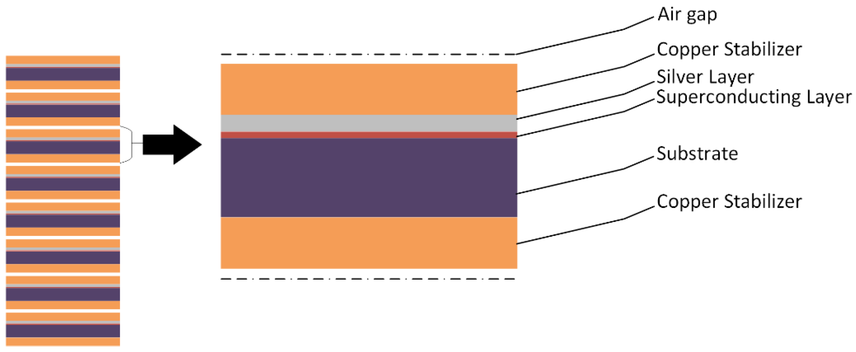
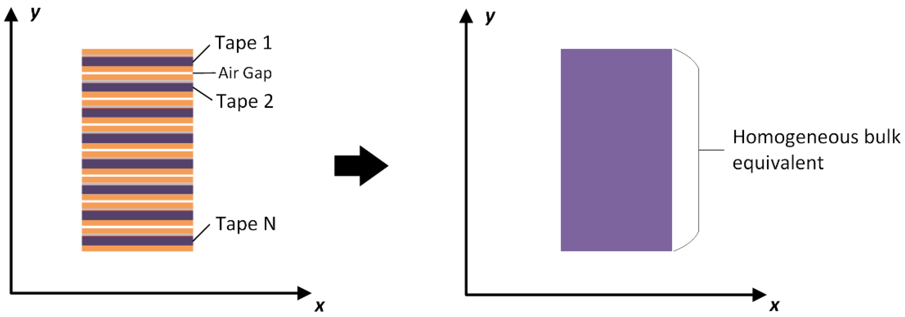
2. Model Description

In this paper, a finite-element-based 2D H-formulation model is used, considering a homogenization technique reported in [14,15], in order to simulate a stack of second-generation high-temperature superconducting tapes subjected to alternating and rotating magnetic fields in the presence of an AC transport current and magnetic field. In order to simulate the electromagnetic behavior of HTSCC, individual layers are modeled in the original stack, whereas the anisotropic homogeneous technique outperforms the traditional H-formulation method in terms of computation time. In order to preserve the general electromagnetic behavior of the original stack, while “washing out” the geometrical arrangement of the alternating interior structures of insulating, metallic, superconducting, and substrate layers, an anisotropic bulk equivalent of the stack was developed. This technique requires less computation time compared to modeling the original stack with individual tapes.
A vertical stack of 64 HTS CCs is considered, as shown in Figure 1. Each tape is manufactured with the ion beam assisted deposition (IBAD) technique, composed of individual layers of silver, YBCO, and substrate, sandwiched with two copper layers, followed by an air gap separating the tape from the next layer. An equivalent anisotropic bulk model can be obtained by “washing out” the tapes’ topological characteristics, as shown in Figure 2. As a result, the material specifications need to be adjusted.

2.1. H-Formulation

There are numerous FEA-based numerical frameworks used to simulate the electromagnetic behavior of HTS, such as A–V formulation [16] based on magnetic vector potential, T–F formulation [17] based on current vector potential, and the most commonly used magnetic field-based H-formulation [18,19]. H-formulation considers certain electrical properties of superconductors by using magnetic field strength as the dependent variable and nonlinear resistivity. It is widely used and accepted by most of researchers around the world because of its precision, good convergence, short computation time, and great concordance with experimental results and analytical models such as the Ginzburg-Landau phenomenological model, the Norris analytical model and the Brandt analytical model [13,20,21]. Moreover, H-formulation also considers the self-consistent calculation of the magnetic field [22].
The H-formulation model is based on the following laws: Maxwell–Ampere’s law (1), Faraday’s law (2), constitutive law (3), Ohm’s law (4), and E–J power law (5).
× H = J
× E = B t
B = μ 0 μ r H
E = ρ J
where J is the current density, E is the electric field strength, ρ is the resistivity, B is the magnetic flux density, µ0 is the permeability of free space, and µr is the relative permeability. The resistivity in Equation (4) is constant for normal materials, but it varies with the current density in superconductors. It usually takes the form of the power law, as follows:
ρ = E 0 J J J c n 1
where E0 is the characteristic electric field strength, Jc is the critical current density, and n represents the steepness of the shift from superconducting to the normal state, usually called the power factor. As n reaches infinity, the power law approaches the critical state model [23], also known as Bean’s critical state model when n approaches infinity. Combining Equations (1)–(5), one obtains the partial differential equation (PDE) in terms of the variable H as follows:
μ 0 μ r H t + × ρ × H = 0
The above-mentioned PDE can be solved using commercially available finite element software such as COMSOL Multiphysics [24]. Using Dirichlet boundary conditions, an external magnetic field may be applied around the sample’s boundary in the air domain. The non-conducting regions are represented by high-resistivity materials. A resistivity value of 1 Ω.m is commonly employed since it is sufficiently large, preventing current flow in non-conducting zones, and it does not significantly increase calculation time. Magnetically, the superconductor is modeled as a material with relative magnetic permeability µr = 1. Furthermore, when J has a parallel component to B, the direction of the current density relative to the magnetic field affects the critical current density, resulting in force-free effects. As a result, high-accuracy models based on Jc(B) and anisotropy dependence are required. To account for the Jc(B) dependency, Kim’s model [25] is also used to consider such an isotropic behavior, as shown below in Equation (7);
J c B = J c 0 1 + B B 0 m
Moreover, the H-formulation is considered to be a powerful tool for computation of the AC loss, ranging from individual tapes to complex cables and large magnet windings [20,21]. To calculate the AC loss, the dot production of vectors E and J is integrated over the domain of interest, as shown below:
Q = 2 T 0.5 T T E · J   d dt
where Ω represents the domain for calculating AC loss and T is the period of AC signal. The other relevant parameters used in the model are listed in Table 1.
Unlike the microscopic investigations on thin superconductors [26,27], this article concentrates on the macroscopic phenomenon of the HTS stack, particularly the overall AC loss in the stack. Therefore, some minor microscopic effects that do not greatly affect the overall AC loss can be neglected.

2.2. Rotating Magnetic Fields

In 1D magnetic fields, the magnetic flux density vector B is restrained to flow in the same direction as the magnetic field intensity H. However, in rotating electrical machines, the magnetic field rotates on a 2D plane, with B and H vectors that may not be pointing in the same direction. In order to set up a magnetic field around the HTS CC stack, an external magnetic field is supplied to the boundaries of the superconducting domain. In the case of a 1D alternating field, a sine wave of the required amplitude is introduced. The applied rotating magnetic field in the case of 2D rotating magnetization, on the other hand, is just a combination of sine waveforms at the borders of two independent axes, according to the testing requirements, which may be described using the following equations:
  B 1 D alt = B 0 sin ω t
B 2 D rot =   B 0 sin ω t     B 0 sin ω t ± ( 1 exp t τ )  
where B0 is the magnetic flux density amplitude, ω is the angular frequency, φ denotes the phase shift angle, and τ is a time constant of 0.05 s. A purely circular rotating field is produced, which is often achieved by adjusting the phase angle of the second source by 90 degrees (i.e., π/2). When a phase angle is shifted along the axis, the magnetic field’s starting value is not equal to zero, which causes an issue with the initial values in FEA and prevents the model from converging. As a result, an exponential step function is used in the second field source in Equation (10) to establish a transitory start in Equation (9). Figure 3 shows the representation of a HTS CC subjected to alternating and rotating magnetic fields while carrying a transport current.

3. Results and Discussion

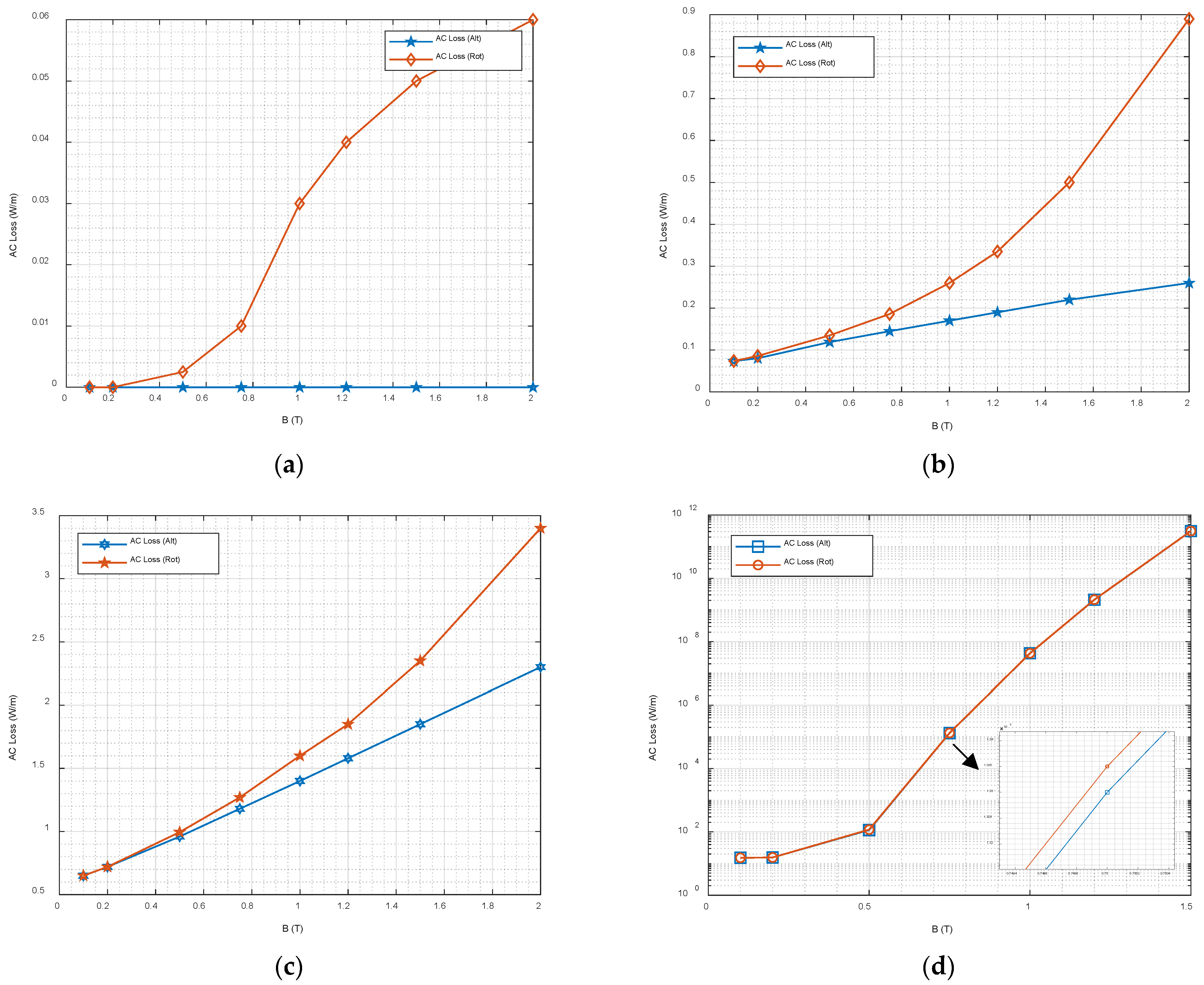
3.1. AC Loss Analysis

The AC loss in HTSCC is the main characteristic that needs to be studied. This paper studies the AC loss of a vertical stack of HTSCC comprising 64 tapes. The stack is subjected to various scenarios comprising alternating and rotating magnetic fields, along with the transport current situation at the same time. Because rotating magnetic fields are most commonly observed in rotating machines and the HTS bulk is a good option for such applications, our work focused mostly on power frequency (50 Hz). For the first case, we only apply the magnetic field across the tapes without any transport current. Magnetic fields of up to 2T are applied in the 1D alternating and 2D rotating patterns, as shown in Figure 4a.
Furthermore, we tried to increase the transport current from 0 A up to 50 A in order to understand the loss mechanism in the HTS CCs by exposing them to alternating and rotating magnetic fields, along with the transport current scenario. Figure 4 shows the AC loss with transport currents of 0 A, 10 A, 20 A, and 50 A.
It can be seen that, with the transport current of 10 A, the AC loss is almost equal for both alternating and rotating magnetizations up to 20 mT. However, it increases significantly up to three times as the magnetic field is increased to 2 T, as shown in Figure 4b. When a transport current is set to 20 A, the loss seems to be similar at 20 mT, but at higher magnetic fields, the difference in the AC loss between alternating and rotating magnetic fields is reduced to 1.5 times, as shown in Figure 4c. Furthermore, when the transport current is increased to 50 A, the rotating, as well as alternating, AC loss becomes almost the same, and there is a negligible difference between the two cases; however, the rotating AC loss is still higher than the alternating AC loss (Figure 4d). The main reason for this is that, at higher currents, the AC loss is mainly due to transport current.

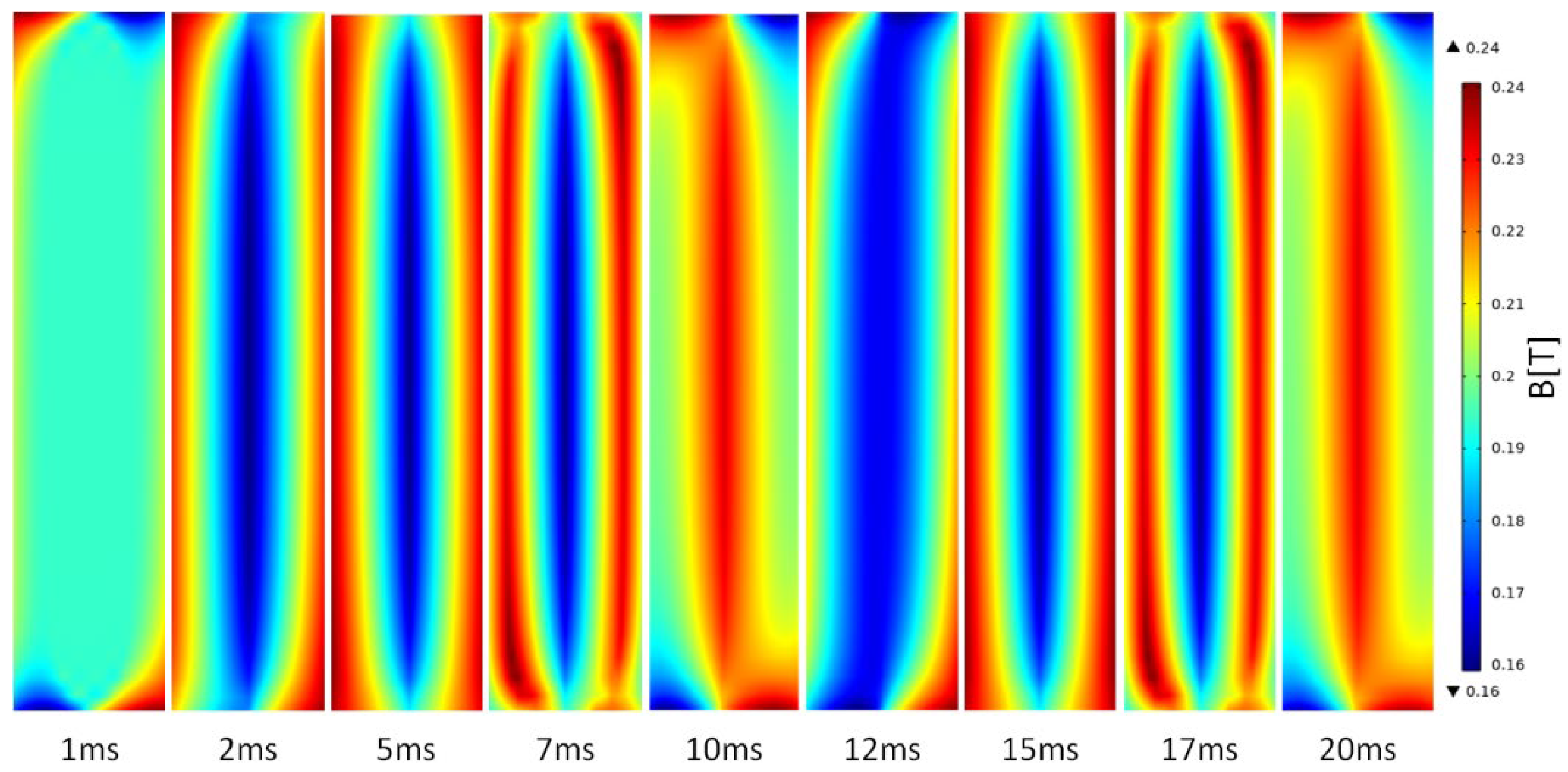
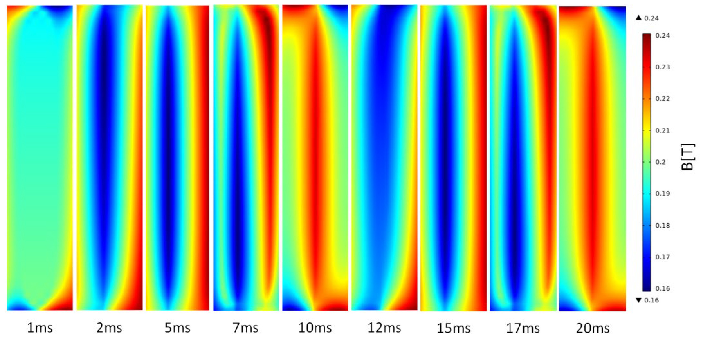
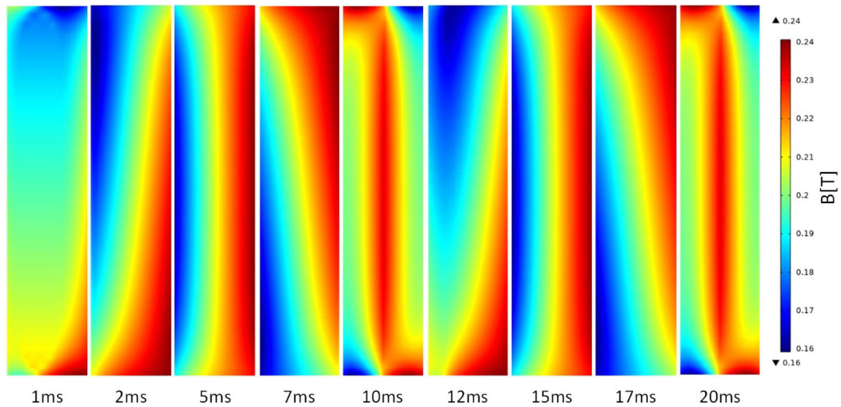
3.2. Flux Density Maps

Figure 5, Figure 6 and Figure 7 show the magnetic flux density distribution maps of the HTS CC stack when a rotating magnetic field is applied with an amplitude of 20 mT. Figure 5 shows such distribution without any transport current scenario. At the start of the excitation, the field is distributed along the sides of the stack and reaches the middle of the stack vertically at 10 ms, and then it fades on the edges. Figure 6 shows the magnetic flux density distribution of the stack but, in this case, a 20 A current is applied, as represented visually in Figure 3. It shows very similar behavior as per the earlier case, but here, a slight drift of the flux density to the left side is observed. Figure 7 shows the flux density distribution when a rotating magnetic field of 20 mT is applied along with the transport current of 50 A. In this case, the flux density is distributed more towards the edges and rotating clockwise around the stack.

4. Conclusions

In this study, the electromagnetic behavior of HTS CCs is investigated using numerical modeling techniques by applying rotating magnetic fields to the stack of HTS CCs. A FEM-based homogenous H-formulation anisotropic bulk model is used, which greatly reduces the model’s computation time. The article predicts the behavior of AC loss under rotating magnetic fields of various amplitudes, along with the transport current situation. Colored maps of flux density distribution are also shown as a reference to demonstrate the real distribution of magnetic flux density in different timesteps and transport currents. As the AC loss investigations under rotating magnetic fields are not explicitly reported in the literature, this article highlights the preliminary investigation on the subject, which reveals that, when HTSCCs are exposed to rotating magnetic fields, the AC loss can be significantly high, which may affect the cooling efficiency. Therefore, such a loss model is essential for the design of future high-efficiency and high-power density electrical machines.
Moreover, this article also concludes the need to further investigate the detailed loss mechanism under rotating magnetic fields, such as AC loss separation in various layers of HTS tapes, frequency dependence, etc. Although numerical models are effective tools for predicting the performance of HTS materials, new analytical models considering the rotating magnetic fields and robust experimental setups are equally critical for investigating the electromagnetic characteristics of HTS materials.

Author Contributions

Conceptualization, W.A.S., Y.G. and J.Z.; Methodology, W.A.S. and B.S.; Software, W.A.S. and B.S.; Supervision, Y.G. and H.L.; Visualization, W.A.S., Y.G. and J.Z.; Writing—original draft, W.A.S. and Y.G.; Writing—review & editing, H.L., J.Z., J.J. and B.S. All authors have read and agreed to the published version of the manuscript.

Funding

This research was funded by Australian Research Council Discovery Project DP180100470.

Data Availability Statement

Not Applicable.

Conflicts of Interest

The authors declare no conflict of interest.

References

  1. Soomro, W.A.; Guo, Y.; Lu, H.Y.; Jin, J.X. Advancements and impediments in applications of high-temperature superconducting material. In Proceedings of the 2020 IEEE International Conference on Applied Superconductivity and Electromagnetic Devices (ASEMD), Tianjin, China, 16–18 October 2020; pp. 1–4. [Google Scholar] [CrossRef]
  2. Chen, M.; Donzel, L.; Lakner, M.; Paul, W. High temperature superconductors for power applications. J. Eur. Ceram. Soc. 2004, 24, 1815–1822. [Google Scholar] [CrossRef]
  3. Amemiya, N.; Kasai, N.; Yoda, K.; Jiang, Z.; Levin, G.A.; Barnes, P.N.; Oberly, C.E. AC loss reduction of YBCO coated conductors by multifilamentary structure. Supercond. Sci. Technol. 2004, 17, 1464–1471. [Google Scholar] [CrossRef] [Green Version]
  4. Shen, B.; Li, C.; Geng, J.; Zhang, X.; Gawith, J.; Ma, J.; Liu, Y.; Grilli, F.; Coombs, T.A. Power dissipation in HTS coated conductor coils under the simultaneous action of AC and DC currents and fields. Supercond. Sci. Technol. 2018, 31, 075005. [Google Scholar] [CrossRef]
  5. Majoros, M.; Ye, L.; Velichko, A.V.; Coombs, T.A.; Sumption, M.D.; Collings, E.W. Transport AC losses in YBCO coated conductors. Supercond. Sci. Technol. 2007, 20, S299–S304. [Google Scholar] [CrossRef]
  6. Xiao, X.; Liu, Y.; Jin, J.; Li, C.; Xu, F. HTS applied to power system: Benefits and potential analysis for energy conservation and emission reduction. IEEE Trans. Appl. Supercond. 2016, 26, 1–9. [Google Scholar] [CrossRef]
  7. Soomro, W.A.; Guo, Y.; Lu, H.Y.; Zhu, J.G.; Jin, J.X.; Shen, B. Numerical investigation of AC loss in HTS bulks subjected to rotating magnetic fields. In Proceedings of the 31st Australasian Universities Power Engineering Conference (AUPEC), Perth, Australia, 26–30 September 2021; pp. 1–5. [Google Scholar] [CrossRef]
  8. Soomro, W.A.; Guo, Y.; Lu, H.; Zhu, J.; Jin, J.; Shen, B. Three-dimensional numerical characterization of high-temperature superconductor bulks subjected to rotating magnetic fields. Energies 2022, 15, 3186. [Google Scholar] [CrossRef]
  9. Ainslie, M.D.; Fujishiro, H. Modelling of bulk superconductor magnetization. Supercond. Sci. Technol. 2015, 28, 053002. [Google Scholar] [CrossRef]
  10. Wang, Y.; Guan, X.; Dai, J. Review of AC loss measuring methods for HTS tape and unit. IEEE Trans. Appl. Supercond. 2014, 24, 1–6. [Google Scholar]
  11. Shen, B.; Li, J.; Geng, J.; Fu, L.; Zhang, X.; Zhang, H.; Li, C.; Grilli, F.; Coombs, T.A. Investigation of AC losses in horizontally parallel HTS tapes. Supercond. Sci. Technol. 2017, 30, 075006. [Google Scholar] [CrossRef]
  12. Grilli, F.; Pardo, E.; Stenvall, A.; Nguyen, D.N.; Yuan, W.; Gömöry, F. Computation of losses in HTS under the action of varying magnetic fields and currents. IEEE Trans. Appl. Supercond. 2014, 24, 78–110. [Google Scholar] [CrossRef]
  13. Grilli, F. Numerical modeling of HTS applications. IEEE Trans. Appl. Supercond. 2016, 26, 1–8. [Google Scholar] [CrossRef]
  14. Zermeno, V.M.R.; Abrahamsen, A.B.; Mijatovic, N.; Jensen, B.B.; Sørensen, M.P. Calculation of alternating current losses in stacks and coils made of second generation high temperature superconducting tapes for large scale applications. J. Appl. Phys. 2013, 114, 173901. [Google Scholar] [CrossRef] [Green Version]
  15. HTS Modelling Workgroup. Available online: http://www.htsmodelling.com (accessed on 28 July 2022).
  16. Lousberg, G.P.; Ausloos, M.; Geuzaine, C.; Dular, P.; Vanderbemden, P.; Vanderheyden, B. Numerical simulation of the magnetization of high-temperature superconductors: A 3D finite element method using a single time-step iteration. Supercond. Sci. Technol. 2009, 22, 055005. [Google Scholar] [CrossRef]
  17. Amemiya, N.; Murasawa, S.-i.; Banno, N.; Miyamoto, K. Numerical modelings of superconducting wires for AC loss calculations. Phys. C Supercond. 1998, 310, 16–29. [Google Scholar] [CrossRef]
  18. Escamez, G.; Sirois, F.; Lahtinen, V.; Stenvall, A.; Badel, A.; Tixador, P.; Ramdane, B.; Meunier, G.; Perrin-Bin, R.; Bruzek, C.-É. 3-D numerical modeling of AC losses in multifilamentary MgB2Wires. IEEE Trans. Appl. Supercond. 2016, 26, 1–7. [Google Scholar] [CrossRef]
  19. Xia, J.; Bai, H.; Lu, J.; Gavrilin, A.V.; Zhou, Y.; Weijers, H.W. Electromagnetic modeling of REBCO high field coils by the H-formulation. Supercond. Sci. Technol. 2015, 28, 125004. [Google Scholar] [CrossRef]
  20. Shen, B.; Grilli, F.; Coombs, T. Overview of H-formulation: A versatile tool for modeling electromagnetics in high-temperature superconductor applications. IEEE Access 2020, 8, 100403–100414. [Google Scholar] [CrossRef]
  21. Shen, B.; Grilli, F.; Coombs, T. Review of the AC loss computation for HTS using H formulation. Supercond. Sci. Technol. 2020, 33, 033002. [Google Scholar] [CrossRef] [Green Version]
  22. Grilli, F.; Sirois, F.; Zermeno, V.M.; Vojenčiak, M. Self-consistent modeling of the Ic of HTS devices: How accurate do models really need to be? IEEE Trans. Appl. Supercond. 2014, 24, 1–8. [Google Scholar]
  23. Bean, C.P. Magnetization of hard superconductors. Phys. Rev. Lett. 1962, 8, 250. [Google Scholar] [CrossRef]
  24. Brambilla, R.; Grilli, F.; Martini, L. Development of an edge-element model for AC loss computation of high-temperature superconductors. Supercond. Sci. Technol. 2006, 20, 16. [Google Scholar] [CrossRef]
  25. Chen, D.X.; Goldfarb, R.B. Kim model for magnetization of type-II superconductors. J. Appl. Phys. 1989, 66, 2489–2500. [Google Scholar] [CrossRef]
  26. Saint-James, D.; Gennes, P.G. Onset of superconductivity in decreasing fields. Phys. Lett. 1963, 7, 306–308. [Google Scholar] [CrossRef]
  27. Croitoru, M.; Shanenko, A.; Chen, Y.; Vagov, A.; Aguiar, J.A. Microscopic description of surface superconductivity. Phys. Rev. B 2020, 102, 054513. [Google Scholar] [CrossRef]
Figure 1. A Vertical Stack of HTS CC and individual layers of sliver layer, superconducting layer, substrate, and two layers of copper stabilizers.
Solids 03 00036 g001
Figure 2. Homogeneous model of the vertical stack of CC, where the real topological characteristics of the tapes are “washed out”.
Solids 03 00036 g002
Figure 3. HTS CC stack subjected to alternating and rotating magnetic fields while transport current is applied.
Solids 03 00036 g003
Figure 4. AC loss in HTS stack subjected to an alternating and rotating magnetic field with transport currents of (a) 0 A, (b) 10 A, (c) 20 A and (d) 50 A.
Solids 03 00036 g004
Figure 5. Magnetic flux density maps for stacks of HTS CC when subjected to rotating magnetic field of 20 mT without any transport current.
Solids 03 00036 g005
Figure 6. Magnetic flux density maps for stacks of HTS CC when subjected to a rotating magnetic field of 20 mT while carrying a transport current of 20 A.
Solids 03 00036 g006
Figure 7. Magnetic flux density B maps for stacks of HTS CC when subjected to a rotating magnetic field of 20 mT while carrying a transport current of 50 A.
Solids 03 00036 g007
Table 1. Model parameters.
ParameterSymbolValue
Insulation/air gaphl200 µm
Copper layerhcu40 µm
Substrate layerhc50 µm
Silver layerhag2 µm
HTS (YBCO) layer thicknesshHTS1 µm
Unit thicknessD293 µm
Tape widtha4 mm
Air/insulation resistivityρIns1 Ω·m
Silver resistivityρAg2.70 nΩ·m
Copper resistivityρCu1.97 nΩ·m
Substrate resistivityρSubs1.25 µΩ·m
Permeability of free spaceμ04π × 10−7 H.m−1
Number of tapes in stackC64
Power factorn38
Critical current densityJc0108 A·mm−2
Characteristic electric fieldE010−4 V m−1
Kim’s model arbitrary parameterB00.0041 T
Kim’s model arbitrary parameterm0.5
Publisher’s Note: MDPI stays neutral with regard to jurisdictional claims in published maps and institutional affiliations.

